EP1494232A1 - Recording medium - Google Patents
Recording medium Download PDFInfo
- Publication number
- EP1494232A1 EP1494232A1 EP03745889A EP03745889A EP1494232A1 EP 1494232 A1 EP1494232 A1 EP 1494232A1 EP 03745889 A EP03745889 A EP 03745889A EP 03745889 A EP03745889 A EP 03745889A EP 1494232 A1 EP1494232 A1 EP 1494232A1
- Authority
- EP
- European Patent Office
- Prior art keywords
- information
- data
- image
- recorded
- file
- Prior art date
- Legal status (The legal status is an assumption and is not a legal conclusion. Google has not performed a legal analysis and makes no representation as to the accuracy of the status listed.)
- Withdrawn
Links
Images


























Classifications
-
- G—PHYSICS
- G11—INFORMATION STORAGE
- G11B—INFORMATION STORAGE BASED ON RELATIVE MOVEMENT BETWEEN RECORD CARRIER AND TRANSDUCER
- G11B20/00—Signal processing not specific to the method of recording or reproducing; Circuits therefor
- G11B20/10—Digital recording or reproducing
- G11B20/12—Formatting, e.g. arrangement of data block or words on the record carriers
- G11B20/1217—Formatting, e.g. arrangement of data block or words on the record carriers on discs
- G11B20/1258—Formatting, e.g. arrangement of data block or words on the record carriers on discs where blocks are arranged within multiple radial zones, e.g. Zone Bit Recording or Constant Density Recording discs, MCAV discs, MCLV discs
-
- H—ELECTRICITY
- H04—ELECTRIC COMMUNICATION TECHNIQUE
- H04N—PICTORIAL COMMUNICATION, e.g. TELEVISION
- H04N5/00—Details of television systems
- H04N5/76—Television signal recording
- H04N5/91—Television signal processing therefor
-
- G—PHYSICS
- G11—INFORMATION STORAGE
- G11B—INFORMATION STORAGE BASED ON RELATIVE MOVEMENT BETWEEN RECORD CARRIER AND TRANSDUCER
- G11B20/00—Signal processing not specific to the method of recording or reproducing; Circuits therefor
- G11B20/10—Digital recording or reproducing
- G11B20/12—Formatting, e.g. arrangement of data block or words on the record carriers
-
- G—PHYSICS
- G11—INFORMATION STORAGE
- G11B—INFORMATION STORAGE BASED ON RELATIVE MOVEMENT BETWEEN RECORD CARRIER AND TRANSDUCER
- G11B27/00—Editing; Indexing; Addressing; Timing or synchronising; Monitoring; Measuring tape travel
-
- G—PHYSICS
- G11—INFORMATION STORAGE
- G11B—INFORMATION STORAGE BASED ON RELATIVE MOVEMENT BETWEEN RECORD CARRIER AND TRANSDUCER
- G11B27/00—Editing; Indexing; Addressing; Timing or synchronising; Monitoring; Measuring tape travel
- G11B27/10—Indexing; Addressing; Timing or synchronising; Measuring tape travel
- G11B27/102—Programmed access in sequence to addressed parts of tracks of operating record carriers
- G11B27/105—Programmed access in sequence to addressed parts of tracks of operating record carriers of operating discs
-
- G—PHYSICS
- G11—INFORMATION STORAGE
- G11B—INFORMATION STORAGE BASED ON RELATIVE MOVEMENT BETWEEN RECORD CARRIER AND TRANSDUCER
- G11B27/00—Editing; Indexing; Addressing; Timing or synchronising; Monitoring; Measuring tape travel
- G11B27/10—Indexing; Addressing; Timing or synchronising; Measuring tape travel
- G11B27/19—Indexing; Addressing; Timing or synchronising; Measuring tape travel by using information detectable on the record carrier
- G11B27/28—Indexing; Addressing; Timing or synchronising; Measuring tape travel by using information detectable on the record carrier by using information signals recorded by the same method as the main recording
- G11B27/32—Indexing; Addressing; Timing or synchronising; Measuring tape travel by using information detectable on the record carrier by using information signals recorded by the same method as the main recording on separate auxiliary tracks of the same or an auxiliary record carrier
- G11B27/327—Table of contents
- G11B27/329—Table of contents on a disc [VTOC]
-
- G—PHYSICS
- G11—INFORMATION STORAGE
- G11B—INFORMATION STORAGE BASED ON RELATIVE MOVEMENT BETWEEN RECORD CARRIER AND TRANSDUCER
- G11B27/00—Editing; Indexing; Addressing; Timing or synchronising; Monitoring; Measuring tape travel
- G11B27/10—Indexing; Addressing; Timing or synchronising; Measuring tape travel
- G11B27/34—Indicating arrangements
-
- H—ELECTRICITY
- H04—ELECTRIC COMMUNICATION TECHNIQUE
- H04N—PICTORIAL COMMUNICATION, e.g. TELEVISION
- H04N5/00—Details of television systems
- H04N5/76—Television signal recording
-
- H—ELECTRICITY
- H04—ELECTRIC COMMUNICATION TECHNIQUE
- H04N—PICTORIAL COMMUNICATION, e.g. TELEVISION
- H04N9/00—Details of colour television systems
- H04N9/79—Processing of colour television signals in connection with recording
- H04N9/80—Transformation of the television signal for recording, e.g. modulation, frequency changing; Inverse transformation for playback
- H04N9/804—Transformation of the television signal for recording, e.g. modulation, frequency changing; Inverse transformation for playback involving pulse code modulation of the colour picture signal components
- H04N9/8042—Transformation of the television signal for recording, e.g. modulation, frequency changing; Inverse transformation for playback involving pulse code modulation of the colour picture signal components involving data reduction
-
- G—PHYSICS
- G11—INFORMATION STORAGE
- G11B—INFORMATION STORAGE BASED ON RELATIVE MOVEMENT BETWEEN RECORD CARRIER AND TRANSDUCER
- G11B20/00—Signal processing not specific to the method of recording or reproducing; Circuits therefor
- G11B20/10—Digital recording or reproducing
- G11B2020/10916—Seeking data on the record carrier for preparing an access to a specific address
-
- G—PHYSICS
- G11—INFORMATION STORAGE
- G11B—INFORMATION STORAGE BASED ON RELATIVE MOVEMENT BETWEEN RECORD CARRIER AND TRANSDUCER
- G11B20/00—Signal processing not specific to the method of recording or reproducing; Circuits therefor
- G11B20/10—Digital recording or reproducing
- G11B20/12—Formatting, e.g. arrangement of data block or words on the record carriers
- G11B2020/1291—Formatting, e.g. arrangement of data block or words on the record carriers wherein the formatting serves a specific purpose
- G11B2020/1294—Increase of the access speed
- G11B2020/1295—Increase of the access speed wherein the focus is on the read access speed
-
- G—PHYSICS
- G11—INFORMATION STORAGE
- G11B—INFORMATION STORAGE BASED ON RELATIVE MOVEMENT BETWEEN RECORD CARRIER AND TRANSDUCER
- G11B2220/00—Record carriers by type
- G11B2220/20—Disc-shaped record carriers
- G11B2220/21—Disc-shaped record carriers characterised in that the disc is of read-only, rewritable, or recordable type
- G11B2220/215—Recordable discs
- G11B2220/216—Rewritable discs
-
- G—PHYSICS
- G11—INFORMATION STORAGE
- G11B—INFORMATION STORAGE BASED ON RELATIVE MOVEMENT BETWEEN RECORD CARRIER AND TRANSDUCER
- G11B2220/00—Record carriers by type
- G11B2220/20—Disc-shaped record carriers
- G11B2220/25—Disc-shaped record carriers characterised in that the disc is based on a specific recording technology
- G11B2220/2537—Optical discs
- G11B2220/2562—DVDs [digital versatile discs]; Digital video discs; MMCDs; HDCDs
-
- G—PHYSICS
- G11—INFORMATION STORAGE
- G11B—INFORMATION STORAGE BASED ON RELATIVE MOVEMENT BETWEEN RECORD CARRIER AND TRANSDUCER
- G11B2220/00—Record carriers by type
- G11B2220/20—Disc-shaped record carriers
- G11B2220/25—Disc-shaped record carriers characterised in that the disc is based on a specific recording technology
- G11B2220/2537—Optical discs
- G11B2220/2562—DVDs [digital versatile discs]; Digital video discs; MMCDs; HDCDs
- G11B2220/2575—DVD-RAMs
-
- H—ELECTRICITY
- H04—ELECTRIC COMMUNICATION TECHNIQUE
- H04N—PICTORIAL COMMUNICATION, e.g. TELEVISION
- H04N5/00—Details of television systems
- H04N5/76—Television signal recording
- H04N5/765—Interface circuits between an apparatus for recording and another apparatus
-
- H—ELECTRICITY
- H04—ELECTRIC COMMUNICATION TECHNIQUE
- H04N—PICTORIAL COMMUNICATION, e.g. TELEVISION
- H04N5/00—Details of television systems
- H04N5/76—Television signal recording
- H04N5/765—Interface circuits between an apparatus for recording and another apparatus
- H04N5/77—Interface circuits between an apparatus for recording and another apparatus between a recording apparatus and a television camera
- H04N5/772—Interface circuits between an apparatus for recording and another apparatus between a recording apparatus and a television camera the recording apparatus and the television camera being placed in the same enclosure
-
- H—ELECTRICITY
- H04—ELECTRIC COMMUNICATION TECHNIQUE
- H04N—PICTORIAL COMMUNICATION, e.g. TELEVISION
- H04N5/00—Details of television systems
- H04N5/76—Television signal recording
- H04N5/78—Television signal recording using magnetic recording
- H04N5/781—Television signal recording using magnetic recording on disks or drums
-
- H—ELECTRICITY
- H04—ELECTRIC COMMUNICATION TECHNIQUE
- H04N—PICTORIAL COMMUNICATION, e.g. TELEVISION
- H04N5/00—Details of television systems
- H04N5/76—Television signal recording
- H04N5/84—Television signal recording using optical recording
- H04N5/85—Television signal recording using optical recording on discs or drums
-
- H—ELECTRICITY
- H04—ELECTRIC COMMUNICATION TECHNIQUE
- H04N—PICTORIAL COMMUNICATION, e.g. TELEVISION
- H04N5/00—Details of television systems
- H04N5/76—Television signal recording
- H04N5/907—Television signal recording using static stores, e.g. storage tubes or semiconductor memories
-
- H—ELECTRICITY
- H04—ELECTRIC COMMUNICATION TECHNIQUE
- H04N—PICTORIAL COMMUNICATION, e.g. TELEVISION
- H04N9/00—Details of colour television systems
- H04N9/79—Processing of colour television signals in connection with recording
- H04N9/7921—Processing of colour television signals in connection with recording for more than one processing mode
-
- H—ELECTRICITY
- H04—ELECTRIC COMMUNICATION TECHNIQUE
- H04N—PICTORIAL COMMUNICATION, e.g. TELEVISION
- H04N9/00—Details of colour television systems
- H04N9/79—Processing of colour television signals in connection with recording
- H04N9/80—Transformation of the television signal for recording, e.g. modulation, frequency changing; Inverse transformation for playback
- H04N9/804—Transformation of the television signal for recording, e.g. modulation, frequency changing; Inverse transformation for playback involving pulse code modulation of the colour picture signal components
- H04N9/806—Transformation of the television signal for recording, e.g. modulation, frequency changing; Inverse transformation for playback involving pulse code modulation of the colour picture signal components with processing of the sound signal
- H04N9/8063—Transformation of the television signal for recording, e.g. modulation, frequency changing; Inverse transformation for playback involving pulse code modulation of the colour picture signal components with processing of the sound signal using time division multiplex of the PCM audio and PCM video signals
-
- H—ELECTRICITY
- H04—ELECTRIC COMMUNICATION TECHNIQUE
- H04N—PICTORIAL COMMUNICATION, e.g. TELEVISION
- H04N9/00—Details of colour television systems
- H04N9/79—Processing of colour television signals in connection with recording
- H04N9/80—Transformation of the television signal for recording, e.g. modulation, frequency changing; Inverse transformation for playback
- H04N9/82—Transformation of the television signal for recording, e.g. modulation, frequency changing; Inverse transformation for playback the individual colour picture signal components being recorded simultaneously only
- H04N9/8205—Transformation of the television signal for recording, e.g. modulation, frequency changing; Inverse transformation for playback the individual colour picture signal components being recorded simultaneously only involving the multiplexing of an additional signal and the colour video signal
-
- H—ELECTRICITY
- H04—ELECTRIC COMMUNICATION TECHNIQUE
- H04N—PICTORIAL COMMUNICATION, e.g. TELEVISION
- H04N9/00—Details of colour television systems
- H04N9/79—Processing of colour television signals in connection with recording
- H04N9/80—Transformation of the television signal for recording, e.g. modulation, frequency changing; Inverse transformation for playback
- H04N9/82—Transformation of the television signal for recording, e.g. modulation, frequency changing; Inverse transformation for playback the individual colour picture signal components being recorded simultaneously only
- H04N9/8205—Transformation of the television signal for recording, e.g. modulation, frequency changing; Inverse transformation for playback the individual colour picture signal components being recorded simultaneously only involving the multiplexing of an additional signal and the colour video signal
- H04N9/8227—Transformation of the television signal for recording, e.g. modulation, frequency changing; Inverse transformation for playback the individual colour picture signal components being recorded simultaneously only involving the multiplexing of an additional signal and the colour video signal the additional signal being at least another television signal
Definitions
- the present invention relates to a readable/writable recording medium and more particularly to a recording medium on which multimedia data including data having various formats, such as animated image data, still image data, audio data and data for data broadcasting, is recorded.
- phase-change disk DVD-RAM having a capacity of several GBytes has been developed.
- MPEG MPEG2
- the DVD-RAM is expected to be a recording/reproducing medium not only for computers but also for the audio/video (AV) technical field.
- a DVD disk, DVD recorder and DVD player that is, embodiments of a conventional information recording medium, recording apparatus and reproducing apparatus, will be described below in the following sequence.
- FIG. 1 is a view illustrating the outer appearance of a DVD recorder apparatus and an example of an interface between the DVD recorder apparatus and related apparatuses. As shown in FIG. 1, a DVD disk serving as an optical disk is loaded into the DVD recorder, and video information is recorded/reproduced. The operations are generally carried out by remote control.
- Both analog and digital signals are available as video information to be input to the DVD recorder; analog broadcasting is available as analog signals, and digital broadcasting is available as digital signals.
- analog broadcasting is received and demodulated by a receiver built in a TV set and input to the DVD recorder as an analog video signal of NTSC or the like; and digital broadcasting is demodulated by an STB (Set Top Box) serving as a receiver to a digital signal and input to the DVD recorder and recorded.
- STB Set Top Box
- video information recorded on a DVD disk is reproduced by the DVD recorder and output to the outside.
- Both analog and digital signals are also available for output, just as in the case of input; the analog signal is directly input to a TV set, and the digital signal passes through the STB, is converted into an analog signal, input to the TV set and displayed on the TV set as images.
- video information is recorded/reproduced on a DVD disk by a DVD camcorder or a personal computer, other than the DVD recorder. Even in the case of a DVD disk on which video information has been recorded by an apparatus other than the DVD recorder, when it is loaded into the DVD recorder, it is played back by the DVD recorder.
- the video information of the above-mentioned analog broadcasting and digital broadcasting is usually accompanied by audio information.
- the accompanied audio information is also recorded/reproduced by the DVD recorder similarly.
- video information is generally formed of animated images, the information may be formed of still images in some cases. For example, this applies to the case wherein still images are recorded by the photographing functions of a DVD camcorder.
- the digital I/F between an external apparatus can be IEEE1394, ATAPI, SCSI, USB, Ethernet, etc.
- NTSC that is, a composite video signal
- component signals for individually transmitting a luminance signal and color difference signals may be used.
- DVI digital I/F
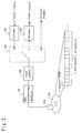
- FIG. 2 is a block diagram showing the functions of the DVD recorder apparatus.
- the drive apparatus thereof comprises an optical pickup 101 that reads the data of a DVD-RAM disk 100, an ECC (Error Correcting Code) processing section 102, a track buffer 103, a switch 104 that switches the input/output of the track buffer 103, an encoder section 105 and a decoder section 106.
- the DVD recorder apparatus may be provided with a semiconductor memory card and a hard disk drive apparatus as a data storage medium, in addition to the DVD-RAM disk.
- FIG. 4 is a block diagram showing a DVD recorder provided with a semiconductor memory card and a hard disk drive apparatus.
- One sector may have 512 B, 8 KB, etc.
- the ECC block may have 1 sector, 16 sectors, 32 sectors, etc. It is expected that the size of the sector and the number of sectors constituting the ECC block increase as the amount of recordable information increases.
- the track buffer 103 is a buffer that is used to record AV data at a variable bit rate (VBR) so that the AV data is more efficiently recorded on the DVD-RAM disk 100.
- VBR variable bit rate
- the read/write rate (Va) to the DVD-RAM disk 100 is a fixed rate
- the bit rate (Vb) changes depending on the complexity of the contents (images in the case of a video signal) of the data, the buffer is used to absorb the difference in this bit rate.
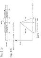
- FIG. 3 (a) is a view showing address space on the disk.
- AV data is separately recorded in a continuous area of [a1, a2] and a continuous area of [a3, a4] as shown in FIG. 3 (a)
- seek is carried out from a2 to a3
- the AV data can be reproduced continuously.
- the condition obtained at this time is shown in FIG. 3 (b).
- the AV data started to be read at position a1 is input to the track buffer 103 at time t1, and data output from the track buffer 103 starts.
- the amount of the data corresponding to the rate difference (Va - Vb) between the rate (Va) of input to the transfer buffer and the rate (Vb) of output from the transfer buffer is begun to be stored. This condition continues until the retrieval area a2 is reached, that is, until time t2 is reached.
- the amount of the data stored in the transfer buffer 103 in this period is B (t2)
- the amount B (t2) stored in the transfer buffer 103 should only be consumed and supplied continuously to the decoder 106 in the period from time t2 to time t3 when data reading from the area a3 starts.
- N_ecc Vb*Tj/ ((N_sec*8*S_size)*(1-Vb/Va))
- a defective sector may occur in the continuous area.
- the continuous area is represented by the following equation.
- dN_ecc is the size of an allowable defective sector
- Ts is the time required for skipping the defective sector in the continuous area. This size is also represented by the number of ECC blocks.
- N_ecc dN_ecc+Vb*(Tj+Ts)/ ((N_sec*8*S_size)*(1-Vb/Va))
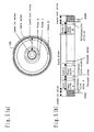
- FIG. 5 is a view showing the outer appearance and the physical structure of the DVD-RAM disk serving as a recordable optical disk.
- the DVD-RAM disk is loaded into a DVD recorder in a state of being generally accommodated in a cartridge. This is done to protect the recording face thereof. However, when the protection of the recording face is done by another configuration or when nonuse of the cartridge is allowable, a configuration wherein the disk can be directly loaded into the DVD recorder without being accommodated in a cartridge is also possible as a matter of course.
- Data is recorded on the DVD-RAM disk by the phase-change system.
- the data recorded on the disk is managed in sector units and accompanied by access-use addresses. Sixteen sectors become an error-correction unit, and an error-correction code is attached thereto; the sectors are referred to as an ECC block.
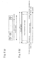
- FIG. 5 (a) is a view showing the recording area of a DVD-RAM disk serving as a recordable optical disk.
- a lead-in area is located in the innermost circumference thereof
- a lead-out area is located in the outermost circumference thereof
- a data area is located therebetween.
- reference signals required for stabilizing servo control during the access time of the optical pickup, signals for discrimination from other media, etc. have been recorded.
- reference signals similar to those in the lead-in area and the like are recorded.
- the data area is divided into sectors (one sector has 2048 bytes), one sector being the minimum access unit.
- the data area of the DVD-RAM disk is divided into plural zone areas to attain rotation control referred to as Z-CLV (Zone Constant Linear Velocity) during recording/reproduction.
- Z-CLV Zero Constant Linear Velocity
- FIG. 5 (a) is a view showing plural zone areas provided concentrically on the DVD-RAM disk.
- the DVD-RAM disk is divided into 24 zone areas, zone 0 to zone 23.
- the rotational angular velocity of the DVD-RAM disk is set for each zone area so that the velocity is higher as the zone is located nearer to the inner interference side; the velocity is maintained constant when the optical pickup gains access in one zone.
- the recording density of the DVD-RAM disk is raised, and rotation control during recording/reproduction is made easy.
- FIG. 5 (b) is a view in which the lead-in area, the lead-out area and the zone areas 0 to 23 shown concentrically in FIG. 5 (a) are illustrated in a lateral direction.
- the lead-in area and the lead-out area have a defect management area (DMA: Defect Management Area) therein.
- the defect management area is an area wherein position information indicating the positions of sectors having defects and the alternative position information indicating which of the above-mentioned alternative areas have sectors alternative to the defective sectors.
- Each zone area has a user area therein and also has an alternative area and an unused area at the boundary section.
- the user area is an area that can be used as a recording area by a file system.
- the alternative area is an area that is used alternatively when a defective sector is present.
- the unused area is an area not used for data recording. About two tracks are provided for the unused area.
- logical sector numbers (LSN: Logical Sector Number) are assigned to the physical sectors of the user areas sequentially from the inner circumference so that only the sectors for data recording are indicated continuously.
- FIG. 6 shows the logical data space of the DVD-RAM disk formed of logical sectors.
- the logical data space is referred to as a volume space in which user data is recorded.
- recorded data is controlled by the file system.
- information for managing a group of sectors for data storage as a file and information for managing a group of files as a directory are recorded in partition spaces in the volume space, and volume structure information for managing partition spaces and the like is recorded at the head and end of the volume area.
- the file system in accordance with this embodiment is referred to as UDF conforming to the ISO13346.
- the sectors in the above-mentioned group of sectors are not necessarily located continuously but located partially scatteringly in the volume space.
- the file system manages a group of sectors located continuously in the volume space as an extent and manages a file as a set of extents.
- FIG. 7 shows the structures of the directories and files of animated image data recorded on the DVD-RAM disk.
- a VIDEO_RT directory is present, and under this, the files of various objects serving as data for reproduction and VIDEO Manager files serving as management information indicating the reproduction sequence and various attributes of these are stored.
- the objects are data conforming to the MPEG standard and available as PS_VOB, TS1_VOB, TS2_VOB, AOB, POB and MNF.
- PS_VOB, AOB and POB are program streams (PS) of MPEG, and TS1_VOB and TS2_VOB are transport streams (TS).
- a program stream has a data structure formed in consideration of storing AV information on a package medium; on the other hand, a transport stream has a data structure formed in consideration of communication media.
- each of PS_VOB, TS1_VOB and TS2_VOB is an object having both video information and audio information, and mainly composed of video information.
- TS1_VOB is an object that is encoded by a DVD recorder and its internal picture structure is managed minutely
- TS2_VOB is an object that is encoded by an apparatus other than the DVD recorder, and its data structure, such as its internal picture structure, is partially unknown.
- TS1_VOB is an object that is obtained when an analog video signal input externally is encoded to a transport stream by the DVD recorder
- TS2_VOB is an object that is obtained when a digital video signal input externally is directly recorded on the disk without being encoded.
- AOB and POB are program streams of MPEG; AOB is an object mainly composed of audio information, and POB is an object mainly composed of still images.
- MNF is a file inherent to a manufacturer, and additional information for supporting the operations of a recording/reproducing apparatus is stored therein.
- PS_VOB PS_VOB
- POB POB
- AOB AOB
- TS1_VOB TS2_VOB
- VOB is used for applications such as movies
- AOB is used for music applications.
- FIG. 20 shows the structure of the directories and files of still image data to be recorded on the DVD-RAM disk.
- the structure of directories and files conforming to the DCF standard is taken as an example and explained herein.
- DCF image root directory directory name: DCIM
- DCF directories for image storage are present thereunder.
- DCF objects serving as reproduction data are stored.
- the DCF objects are a group of files recorded in conformity with DCF and includes DCF Basic files, DCF extended image files, DCF thumbnail files, etc.
- the DCF Basic file is recorded directly under the DCF directory, has a DCF file name and an extension "JPG," conforms to the Exif standard and is an image file having the data structure determined by the DCF standard.
- the DCF extended image file is recorded directly under the DCF directory and has a DCF file name, but is an image file having an extension and a data structure different from those of the DCF Basic file.
- the DCF thumbnail file is a compressed file for recording the thumbnails of the DCF extended image file.
- FIG. 8 is a view showing the structure of MPEG data to be recorded as various AV objects on the DVD disk.
- a video stream and an audio stream are divided and multiplexed individually.
- a stream obtained after multiplexing is referred to as a system stream.
- VOB Video Object
- the unit of division is referred to as a pack packet having a data amount of about 2 KBytes.
- the video stream is encoded in conformity with the MPEG standard and compressed at a variable bit rate; a complicated image, such as an image with quick motion or the like, has a high bit rate.
- video pictures are classified into I-, P- and B-pictures and encoded.
- the I-picture has been subjected to space-wise compression encoding that is completed within a frame
- the P- and B-pictures have been subjected to time-wise compression encoding that is carried out by utilizing the correlation between frames.
- at least a zone including an I-picture is managed as GOP (Group of Picture). GOP becomes an access point during special reproduction, such as fast-forward reproduction. This is because it has an I-picture compressed within a frame.
- AC3 or LPCM encoding is used in addition to MPEG audio AAC and MP3, in the case of DVD.
- VOBU Video Object Unit
- PS program stream
- TS transport stream
- FIG. 9 is a view illustrating the general descriptions of the data structures of the program stream and the transport stream.
- the unit of transmission and multiplexing of a transport stream is formed of a TS packet having a fixed length.
- the size of the TS packet is 188 B so as to be matched with the ATM transmission serving as a communication standard.
- One or more TS packets being gathered constitute a PES packet.
- the PES packet is based on a concept being common in the program stream and transport stream, and their data structures are common. Packets stored in the packs of the program stream directly constitute a PES packet, and one or more gathered TS packets of the transport stream constitute a PES packet.
- the PES packet is the minimum unit of encoding, and video information and audio information being common in encoding are respectively stored therein. In other words, video information and audio information being different in encoding are not stored in a mixed state in one PES packet.
- video information and audio information being different in encoding are not stored in a mixed state in one PES packet.
- FIGS. 10 and 11 show the data structures of the transport stream and the program stream individually.
- the TS packet is formed of a TS packet header, an adaptation field and a payload section.
- PID Packet Identifier
- each type of streams such as a video stream or an audio stream, to which the TS packet belongs, is identified.
- PCR Program Clock Reference
- STC standard clock
- DTS Decoding Time Stamp
- PTS Presentation Time Stamp
- DTS indicates the decoding timing of a picture/audio frame to be stored in the PES packet
- PTS indicates the presentation timing of video/audio output or the like. Not all PES packet headers are required to have PTS and DTS; if PTS and DTS are present in the PES packet wherein the head data of an I-picture is begun to be stored, decoding and output are carried out without hindrance.
- a random access indication flag is stored in the adaptation field, and the flag indicates as to whether the data located at the video/audio frame head having a possibility of becoming an access point is stored or not in the corresponding payload section.
- a unit start indication flag indicating the start of a PES packet and adaptation field control information indicating as to whether the adaptation field follows or not are also stored in the header section of the TS packet.
- FIG. 11 shows the structures of packs constituting a program stream.
- the pack has SCR and Stream ID in the pack header thereof.
- SCR is substantially identical to PCR of the transport stream
- Stream ID is also substantially identical to PID.
- PTS and DTS are stored in the PES header.
- One of the great differences between the program stream and the transport stream is that multi-programs are allowed to be used for the transport stream.
- the program stream only one program can be transmitted when transmission is carried out in program units; however, in the case of the transport stream, it is assumed that plural programs are transmitted simultaneously.
- the transport stream it is necessary for a reproducing apparatus to identify whether the stream for forming each program is a video stream or an audio stream.
- FIG. 13 shows a PAT table and PMAP tables for transmitting the configuration information of an audio stream and a video stream forming a program.
- information regarding the combination of a video stream and an audio stream used for each program is stored in the PMAP table, and information regarding the combination of a program and a PMAP table is stored in the PAT table.
- the reproducing apparatus can detect the video stream and the audio stream for forming the program requested to be output by the PMAP table.
- FIG. 14 16 sectors constitute an ECC block.
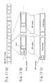
- the packs (PS Packs) constituting a video object (PS_VOB) having the form of a program stream are located depending on the sector boundaries as shown in FIG. 14 (b). This is because both the size of the pack and the size of the sector are 2 KB.
- the video objects (TS1-VOB/TS2-VOB) having the form of a transport stream are located in the ECC block in units of 8 KB size referred to as a capsule.
- the capsule has a header area of 18 B, and 43 TS packets, to which ATS information has been added, are located in the data area.
- the ATS information (Arrival Time Stamp Information) is information that is generated and added by the DVD recorder and indicates timing transmitted to the DVD recorder from the outside.
- FIGS. 15 and 16 are views showing the data structure of a file referred to as video management information (Video Manager) shown in FIG. 7.
- the video management information has object information indicating management information, such as the recording position of each object on a disk, and reproduction control information indicating the reproduction sequence and the like of the objects.
- FIG. 15 shows a case wherein PS-VOB#1 to PS-VOB#n, TS1-VOB#1 to TS1-VOB#n and TS2-VOB#1 to TS2-VOB#n are available as objects to be recorded on a disk.
- the information table for PS-VOB, the information table for TS1-VOB and the information table for TS2-VOB are present individually, and each information table has the VOB information of each object.
- the VOB information has the general information of the corresponding object, the attribute information of the object, an access map of converting the reproduction time of the object into an address on a disk and management information of the access map.
- the general information has the identification information of the corresponding object, the recording time of the object, manufacturer's ID, etc.; and the attribute information comprises video stream information (V_ATR) including the coding mode of the video stream, the number of audio streams (AST_Ns), and audio stream information (A_ATR) including the coding mode of the audio stream.
- the access map is required.
- the first is to prevent reproduction path information from directly making reference to the recording position of an object on a disk by using a sector address or the like so that the reference can be carried out indirectly by using the reproduction time of the object.
- the recording position of an object may be changed by editing or the like in some cases; however, in the case when the reproduction path information directly makes reference to the recording position of the object by using a sector address or the like, the amount of the reproduction path information to be renewed increases.
- the access map should only be renewed.
- the AV stream generally has two references based on time axis and data (bit string) axis and that there is no complete correlation between these two references.
- the method of using variable bit rate (the method of changing the bit rate depending on the complexity of image quality) is going to be mainstream; in this case, random access based on time axis cannot be carried out since there is no proportional relationship between the amount of data from the head and reproduction time.
- the object information has the access map for carrying out conversion between the time axis and the data (bit string) axis.
- the reproduction control information has a user-defined reproduction path information table, an original reproduction path information table and a title search pointer.
- reproduction paths there are two types of reproduction paths: original defined reproduction path information that is automatically generated to indicate all objects recorded by the DVD recorder during object recording and user-defined reproduction path information wherein the user can define reproduction sequence as desired.
- the reproduction path is consistently referred to as PGC information (Program Chain Information); furthermore, the user-defined reproduction path information is referred to as U-PGC information, and the original reproduction path information is referred to as O-PGC information.
- Each of the O-PGC information and the U-PGC information is information wherein cell information serving as information indicating cells used as reproduction zones of an object is listed in a table form.
- the reproduction zone of the object indicated by the O-PGC information is referred to as an original cell (O-CELL), and the reproduction zone of the object indicated by the U-PGC information is referred to as a user cell (U-CELL).
- the cell indicates a reproduction zone of the object by using the reproduction start time and the reproduction end time of the object, and the reproduction start time and the reproduction end time are converted into the recording position information of the object on an actual disk by the above-mentioned access map.
- the cells indicated by the PGC information form a reproduction sequence that is reproduced sequentially in accordance with the sequence of table entry.
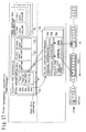
- FIG. 17 is a view specifically illustrating the relationship among object, cell, PGC and access map.
- original PGC information 50 includes at least one piece of cell information 60, 61, 62 and 63.
- the cell information 60 designates an object to be reproduced and also designates the type of the object and the reproduction zone of the object.
- the cell information recording sequence in the PGC information 50 indicates reproduction sequence at the time when the object designated by each cell is reproduced.
- One piece of cell information 60 includes type information (Type) 60a indicating the type of the object designated thereby, object ID (Object ID) 60b serving as the identification information of the object, start time information (Start_PTM) 60c inside the object on the time axis, end time information (End_PTM) 60d inside the object on the time axis, and Entry Point information (EPI) 60e.
- EPI is stipulated by time information and plays a role as a bookmark, for example. The number of Entry Points in a cell is recorded in the cell information although not shown in the figure.
- EPI comprises PTM of the Entry Point thereof, the type information of the Entry Point, etc.
- the cell information 60 in the PCG information 50 is read out sequentially, and an object designated by each cell is reproduced; the amount to be reproduced corresponds to the reproduction zone designated by the cell.
- An access map 80c converts the start time information and the end time information indicated by the cell information into the position information of the object on the disk.
- the above-mentioned map information is generated and recorded at the time when the object is recorded. To generate the map, it is necessary to analyze the picture structures in object data. More specifically, it is necessary to detect the position of the I-picture shown in FIG. 9 and to detect time stamp information, such as PTS serving as the reproduction time of the I-picture, shown in FIGS. 10 and 11.
- PS-VOB and TS1-VOB are mainly generated when received analog broadcasting is encoded to MPEG streams by a DVD recorder.
- the I-picture and various time stamp information are self-generated; since the data structures in the streams are obvious for the DVD recorder, the generation of the map information is attained without causing problems.
- received digital broadcasting is mainly recorded directly on the disk, without being encoded by the DVD recorder.
- the position of the I-picture and the time stamp information are not self-generated; therefore, the data structures in the streams are not obvious for the DVD recorder; it is thus necessary to detect such information from digital streams to be recorded. Therefore, as described below, the DVD recorder detects the I-picture and time stamp with respect to the TS2-VOB map information wherein streams encoded outside the DVD recorder are recorded.
- the detection of the I-picture is carried out by detecting the random access indication information of the adaptation field of the TS packet shown in FIG. 12.
- the detection of the time stamp is carried out by detecting PTS of the PES header.
- PCR of the adaptation field or ATS serving as the timing of the arrival of a TS packet transmitted to the DVD recorder is used instead of PTS in some cases.
- the DVD recorder without analyzing the data structure of the video layer of the MPEG stream, the DVD recorder detects the position of the I-picture in accordance with the information of the system layer that is a layer higher than that. This is because the load to the system becomes large if the analysis is carried out up to the video layer to generate map information.
- the detection of the system layer is impossible in some cases; in such a case, no map information can be generated, whereby it is necessary to indicate that no effective map information is present.
- the map management information shown in FIG. 15 (b) by the DVD recorder.
- the map management information has map effectiveness information and a self-encoding flag.
- the self-encoding flag indicates that the object is self-encoded by the DVD recorder, that the internal picture structure is definite and that the time stamp information, the position information of the I-picture, etc. of the map information are accurate.
- the map effectiveness information indicates as to whether an effective access map is present or not.
- the detection of the system layer is impossible, it may be able to think of a case wherein no adaptation field is set or the digital stream is not the MPEG transport stream in the first place.
- the DVD recorder records objects from which no map can be generated. For example, in the case when a DVD recorder that is assumed to be used for digital broadcasting of Japan is used in the U.S.A. to record digital broadcasting of the U.S.A., there is a case wherein objects from which no map can be generated are recorded.
- the DVD recorder can sequentially reproduce even an object from which no map information can be generated, from its head.
- the recorded digital stream is output to STB corresponding to the stream via a digital I/F, whereby this can be subjected to image reproduction.
- the player comprises an optical pickup 201 that reads data from a DVD-RAM disk 100, an ECC processing section 202 that carries out processing, such as error correction of readout data, a track buffer 203 that temporarily stores error-corrected readout data, a PS decoder 205 that reproduces program streams, such as animated image objects (PS_VOB), a TS decoder 206 that reproduces the transport streams of digital broadcasting objects (TS1_VOB), an audio decoder 207 that reproduces audio objects (AOB), a still image decoder 208 that decodes still image objects (POB), a switch 210 that switches data input to the decoders 205 and 206, and a control section 211 that controls the respective sections of the player.
- PS_VOB animated image objects
- TS decoder 206 that reproduces the transport streams of digital broadcasting objects
- AOB audio decoder
- POB still image objects
- the data recorded on the DVD-RAM disk 100 is read by the optical pickup 201 and stored in the track buffer 203 via the ECC processing section 202.
- the data stored in the track buffer 203 is input to the PS decoder 205, the TS decoder 206, the audio decoder 207 or the still image decoder 208, and then decoded and output.
- control section 211 determines data to be read on the basis of the reproduction sequence indicated by the reproduction path information (PGC) shown in FIG. 16.
- PPC reproduction path information
- the control section 211 carries out control, that is, first reproduces the zone (CELL#1) of VOB#1, then reproduces the zone (CELL#2) of VOB#3, and finally reproduces VOB#2 ((CELL#3).
- control section 211 can obtain the type of the cell to be reproduced, the corresponding object, and the reproduction start time and reproduction end time of the object.
- the control section 211 inputs the data in the object zone specified by the cell information to an applicable decoder.
- the control section 211 specifies the object to be reproduced. Besides, the control section 211 specifies the cell serving as the reproduction zone of the specified object by converting StartPTM and EndPTM of the cell information into the addresses of the disk information in accordance with the access map of the corresponding VOB information.
- the player of this embodiment is further provided with a digital interface 204 that supplies AV streams to the outside.
- AV streams can also be supplied to the outside via communication means, such as IEEE1394, IEC958, etc.
- communication means such as IEEE1394, IEC958, etc.
- TS2-VOB in the case of TS2-VOB that is not self-encoded, no corresponding decoder may be present inside the player; hence, TS2-VOB can be directly output to an external STB via the digital interface 204 without being decoded and can be reproduced by the STB.
- the control section 211 makes a judgment as to whether random access reproduction is possible or not, on the basis of the map management information shown in FIG. 15 (b). If the access point information flag is effective, the access map has the position information of I-picture. Hence, if the request for fast-forward reproduction or the like is issued from an external apparatus, the control section 211 can output digital data including the I-picture to the external apparatus via the digital I/F, depending on this request. In addition, if the time access information flag is effective, time access is possible. Hence, the control section 211 can output digital data including the corresponding picture data to the external apparatus via the digital I/F at a designated reproduction time depending on the time access request from the external apparatus. (7. Basic operations of recording function)
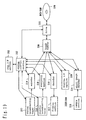
- the DVD recorder comprises a user I/F section 222 that accepts display to the user and accepts requests from the user, a system control section 212 that carries out the overall management and control of the DVD recorder, an analog broadcasting tuner 213 that receives VHF and UHF, an encoder 214 that converts analog signals into digital signals and encodes them to MPEG program streams, a digital broadcasting tuner 215 that receives digital satellite broadcasting, an analyzing section 216 that analyzes MPEG transport streams being sent by a digital satellite, a display section 217, such as a TV set and a speaker, and a decoder 218 that decodes AV streams.
- a user I/F section 222 that accepts display to the user and accepts requests from the user
- a system control section 212 that carries out the overall management and control of the DVD recorder
- an analog broadcasting tuner 213 that receives VHF and UHF
- an encoder 214 that converts analog signals into digital signals and encodes them to MPEG program streams
- the recorder is a DVD camcorder
- it is provided with a camera section 223 that inputs images and a still image encoder 224 that encodes the AV signal sent from the camera section 223 to JPEG streams.
- the decoder 218 comprises the first and second decoders and the like shown in FIG. 18. Furthermore, the DVD recorder comprises a digital I/F section 219, a track buffer 220 that temporarily stores written data, and a drive 221 that writes data on the DVD-RAM disk 100.
- the digital I/F section 219 is an interface, such as IEEE1394 or USB, which outputs data to an external apparatus via communication means.
- the user I/F section 222 first receives a request from the user.
- the user I/F section 222 transmits the request from the user to the system control section 212, and the system control section 212 interprets the request from the user and issues a processing request to each module.
- Self-encoding wherein digital data to be input is self-encoded, and outside encoding wherein encoded digital data is recorded on a disk without being encoded are available for image recording. (7.1 Image recording operation by self-encoding)
- the system control section 212 requests the analog broadcasting tuner 213 to carry out reception and requests the encoder section 214 to carry out encoding.
- the encoder section 214 carries out video encoding, audio encoding and system encoding for AV data being sent from the analog broadcasting tuner 213 and carries out transmission to the track buffer 220.
- the encoder section 214 transmits time stamp information included in the head data of the MPEG program stream being encoded as reproduction start time (PS_VOB_V_S_PTM) to the system control section 212, and then transmits information necessary for creating an access map to the system control section 212 concurrently with the encoding.
- This value is set in Start_PTM of the cell information shown in FIG. 17, which is generated later.
- PTS is generally used as the time stamp information, but SCR may be used instead.
- the system control section 212 issues a recording request to the drive 221, and the drive 221 fetches the data stored in the track buffer 220 and records the data on the DVD-RAM disk 100.
- the above-mentioned continuous areas (CDA) are retrieved from the recordable area on the disk, and the data is recorded in the retrieved continuous areas.
- the end of the image recording is instructed by a stop request from the user.
- the image recording stop request from the user is transmitted to the system control section 212 via the user I/F section 222, and the system control section 212 issues a stop request to the analog broadcasting tuner 213 and the encoder section 214.
- the encoder 214 receives the encoding stop request from the system control section 212, stops encoding, and finally transmits the time stamp information included in the end data of the encoded MPEG program stream as a reproduction end time (PS_VOB_V_E_PTM) to the system control section 212.
- PS_VOB_V_E_PTM reproduction end time
- This value is set in End_PTM of the cell information shown in FIG. 17.
- PTS is usually set as the time stamp information, but SCR may be used instead.
- the system control section 212 After the end of the encoding, on the basis of the information received from the encoder 214, the system control section 212 generates VOB information (PS-VOBI) for PS-VOB shown in FIG. 15 and reproduction control information.
- the VOB information generated at this time includes an access map adapted for the type of the object and map management information.
- the system control section 212 effectively sets the map effectiveness information of the map management information and sets the self-encoding flag at ON.
- the original reproduction path shown in FIG. 16, wherein an object to be recorded is one target to be reproduced.
- the generated O-PGC information is additionally written in the original reproduction path table.
- the original reproduction path has cell information. "PS-VOB" is set as the type information of the cell information.
- the system control section 212 issues a request that the recording of the data stored in the track buffer 220 should be ended and also issues a request that the VOB information for PS-VOB (PS_VOBI) and reproduction control information should be recorded, and the drive 221 records the remaining data of the track buffer 220 and these information on the DVD-RAM disk 100, whereby the image recording is ended.
- PS_VOBI PS-VOB
- Analog broadcasting may be encoded to TS1-VOB as a matter of course.
- the encoder 214 is required to be an encoder that converts an analog signal into a digital signal and encodes the signal to an MPEG transport stream; the type information in the cell information is set in "TS1-VOB.”
- PTS or PCR may be used for Start_PTM and End_PTM. (7.2 Image recording operation by outside encoding)
- a digital broadcasting recording request by the user is transmitted to the system control section 212 via the user I/F section 222.
- the system control section 212 requests the digital broadcasting tuner 215 to carry out reception and requests the analyzing section 216 to carry out data analysis.
- the MPEG transport stream transmitted from the digital broadcasting tuner 215 is transferred to the track buffer 220 via the analyzing section 216.
- the analyzing section 216 extracts the time stamp information included in the head data of the transport stream as start time information (TS2_VOB_V_E_PTM) and transmits the information to the system control section 212.
- the start time information is set in Start_PTM of the cell information shown in FIG. 17, which is generated later. This time stamp information becomes PCR or PTS.
- ATS serving as the timing of the transmission of an object to the DVD recorder may also be used instead.
- the analyzing section 216 analyzes the system layer of the MPEG transport stream and detects information required for access map creation.
- the position of the I-picture in an object is detected on the basis of the random access indicator (random_access_indicator) in the adaptation field (adaptation_field) in the TS packet header as described above.
- the system control section 212 outputs a recording request to the drive 221, and the drive 221 fetches the data stored in the track buffer 220 and records the data on the DVD-RAM disk 100.
- the system control section 212 additionally gives an instruction to the drive 221 as to the recording position on the disk in accordance with the allocation information of the file system.
- the above-mentioned continuous areas (CDA) are retrieved from the recordable area on the disk, and data is recorded in the retrieved continuous areas.
- the end of the image recording is instructed by a stop request from the user.
- the image recording stop request from the user is transmitted to the system control section 212 via the user I/F section 222, and the system control section 212 issues a stop request to the digital broadcasting tuner 215 and the analyzing section 216.
- the analyzing section 216 receives the analysis stop request from the system control section 212 and stops analysis, and finally transmits the time stamp information included in the data in the end zone of the analyzed MPEG transport stream as an indication end time (TS2_VOB_V_E_PTM) to the system control section 212.
- This value is set in End_PTM of the cell information shown in FIG. 17.
- This time stamp information becomes PCR or PTS.
- ATS serving as the timing of the transmission of an object to the DVD recorder may be used instead.
- the system control section 212 After the end of the digital broadcasting reception, on the basis of the information received from the analyzing section 216, the system control section 212 generates VOB information for TS2-VOB (TS2_VOBI) shown in FIG. 15 and reproduction control information.
- the VOB information generated at this time includes an access map adapted for the type of the object and map management information.
- the system control section 212 effectively sets the map effectiveness information of the map management information in the case when the position of the I-picture in the object and the like can be detected and an effective access map is generated.
- the self-encoding flag is set at OFF.
- the map effectiveness information is set invalid. It is considered that the case wherein no effective access map can be generated corresponds to a case wherein non-adaptable digital broadcasting is received, a case wherein random access information is not present in the adaptation field, and the like.
- the information may not be an MPEG transport stream; in this case, the map effectiveness information is also set invalid as a matter of course.
- the original reproduction path shown in FIG. 16, wherein an object to be recorded is one object to be reproduced.
- the generated O-PGC information is additionally written in the original reproduction path table.
- the original reproduction path (O-PGC information) has cell information. "TS2-VOB" is set as the type information of the cell information.
- the system control section 212 issues a request that the recording of the data stored in the track buffer 220 should be ended and also issues a request that the VOB information for TS2-VOB (TS2-VOBI) and reproduction control information should be recorded, and the drive 221 records the remaining data of the track buffer 220 and these information on the DVD-RAM disk 100, whereby the image recording is ended.
- TS2-VOB TS2-VOBI
- the system control section 212 requests the camera section 223 to output the AV data and requests the still image encoder section 224 to carry out encoding.
- the still image encoder section 224 JPEG-encodes the AV data transmitted from the camera section 223 and transmits the data to the track buffer 220.
- the system control section 212 issues a recording request to the drive 221, and the drive 221 fetches the data stored in the track buffer 220 and records the data on the DVD-RAM disk 100.
- the system control section 212 creates a DCF image root directory and a DCF directory as necessary from the information of the file system, gives them names so that the names do not coincide with the file names of DCF objects having been recorded already and records a still image file on the DVD-RAM disk 100.
- the image recording is ended. Or, in the case when continuous photographing is instructed from the user, the recording is ended by a stop request from the user or after a predetermined number of still image files are recorded.
- the image recording stop request from the user is transmitted to the system control section 212 via the user I/F section 222, and the system control section 212 issues a stop request to the camera section 223 and the still image encoder section 224. (7.4 Still image recording operation by outside encoding)
- the DCF object transmitted from the digital I/F section 219 is transmitted to the track buffer 220.
- the system control section 212 outputs a recording request to the drive 221, and the drive 221 fetches the data stored in the track buffer 220 and records the data on the DVD-RAM disk 100.
- the system control section 212 creates a DCF image root directory and a DCF directory as necessary from the information of the file system, gives them names so that the names do not coincide with the file names of DCF objects having been recorded already and records a still image file on the DVD-RAM disk 100.
- the operation of the file system information on the DVD-RAM disk 100 (the creation of the DCF directory, the setting of the DCF object name and the like) on the PC side is carried out in some cases.
- the image recording is ended.
- the image recording is ended by a stop request from the user or after a predetermined number of still image files are recorded.
- the image recording stop request from the user is transmitted to the system control section 212 via the user I/F section 222, and the system control section 212 issues a stop request to the digital I/F section 219.
- WO 02/23898 is available as a recording format of the DVD-RAM disk, which makes the quick retrieval and browsing of the imported still images possible.
- the recording format of WO 02/23898 will be described below.
- FIG. 62 shows a DVD-RAM disk 301 in which plural still image files (DSC objects) 302, 303 and 304 are stored.
- the left side on the page corresponds to the inner circumference side of the DVD-RAM disk 301, and the right side corresponds to the outer circumference side of the DVD-RAM disk 301.
- the three still image files 302, 303 and 304 are recorded; however, in reality, it is assumed that many still image files 302, 303 and 304 have been recorded.
- Each of the still image files 302, 303 and 304 is formed of a set of annexed information and compressed data.
- the compressed data is, for example, data of photographed JPEG images.
- the annexed information includes thumbnail image data that is used in the case when the JPEG image data undergoes thumbnail display and also includes metadata, such as date information, aperture and shutter speed, for retrieving the still image files 302, 303 and 304.
- the still image files 302, 303 and 304 stored on the DVD-RAM disk 301 shown in FIG. 62 undergoes thumbnail display, it is necessary to access each of the still image files 302, 303 and 304 and to read the thumbnail image data of each of the annexed information.
- the reproducing apparatus requires many seek operations to read the thumbnail image data of each of the annexed information.
- the thumbnail display has a problem of taking a time.
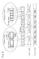
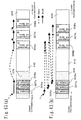
- FIG. 63 (a) shows a DVD-RAM disk 305 on which still image files (DSC objects) are recorded by the method of WO 02/23898.
- the left side on the page corresponds to the inner circumference side of the DVD-RAM disk 305
- the right side corresponds to the outer circumference side of the DVD-RAM disk 305.
- the annexed information portion and the compressed data portion of each still image file have been recorded at respectively different recording areas on the DVD-RAM disk 305.
- the compressed data constituting the still image files is recorded.
- the annexed information (306a) and the compressed data 306b of a still image file comprising the annexed information (306a) and the compressed data 306b are respectively recorded in the area 309 on the inner circumference side and the area 310 on the outer circumference side of the DVD-RAM disk 305 separately.
- Thumbnail display by using the DVD-RAM disk 305 is carried out by only sequentially reading the annexed information (306a), annexed information (307b) and annexed information (308a) stored in the area 309 on the inner circumference side of the DVD-RAM disk 305 in the direction from the inner circumference side to the outer circumference side of the disk, for example.
- long-time seek operation in the case of the DVD-RAM disk 301 shown in FIG. 62 does not generate.
- thumbnail display can be attained quickly even if large amounts of still image files have been recorded on the DVD-RAM disk 305.
- each piece of the annexed information can be accessed by fewer seek operations, whereby the retrieval can be carried out quickly.
- FIG. 63 (b) shows the operation in the case when the still images of a still image file are displayed.
- the still images of the still image file it is necessary to access both the annexed information and compressed data constituting the still image file.
- the compressed data 306b recorded in the area 310 on the outer circumference side of the DVD-RAM disk 305 it is necessary to access the compressed data 306b recorded in the area 310 on the outer circumference side of the DVD-RAM disk 305; a seek operation is thus generated as shown in FIG. 63 (b).
- a problem of generating a long-time seek operation occurs.
- the coordination between animated image data and still image data can be carried out smoothly.
- the recording sequence of the animated image data and still image data recorded in different data formats is stored, it is reproduced during reproduction, or images are reproduced in a format adapted for animated images, such as MPEG, in an animated image zone; on the other hand, high-precision JPEG data images are subjected to display or the like in a still image reproduction zone.
- the present invention is intended to provide a recording medium capable of increasing processing speed at the time when a still image is retrieved by designating aperture, shutter speed, etc. during recording.
- the present invention is intended to provide a recording medium capable of increasing thumbnail index display speed.
- the present invention is intended to provide a recording medium capable of increasing still image file importing speed.
- the present invention is intended to provide a recording medium capable of increasing still image file displaying speed.
- the present invention is intended to provide a recording medium capable of attaining smooth coordinated reproduction of animated image data and still image data recorded on a DVD-RAM disk.
- the present invention is intended to provide a recording medium capable of attaining reproduction of AV data without confusing the user even in the case of coordinated reproduction of animated image data and still image data by using an apparatus other than the apparatus used for recording.
- a first invention of the present invention is a recording medium on which plural image files having image information and annexed information relating to said image information are recorded, wherein said plural image files are recorded in a first area, and the whole copy or plural partial copies of said annexed information respectively corresponding to said plural image files are recorded in a second area different from said first area.
- a second invention of the present invention is a recording medium in accordance with the first invention of the present invention, wherein said annexed information includes at least the thumbnail image information of said image information or retrieval information for retrieving said image information, and the whole copy or partial copies of said annexed information include at least the copies of the thumbnail image information of said image information or the whole copy or partial copies of the retrieval information for retrieving said image information.
- a third invention of the present invention is a recording medium in accordance with the first invention to the present invention, wherein said first area is a user area in which data used by the user can also be recorded, and said second area is a management area in which management information for managing said data is recorded.
- a fourth invention of the present invention is a recording medium in accordance with the third invention of the present invention, wherein only said annexed information is recorded in said second area.
- a fifth invention of the present invention is a recording medium in accordance with the first invention of the present invention, wherein said image file is an Exif image file, said image information is an Exif Primary image and EOI (end of image) included in said Exif image file, said annexed information is APP1 (application data segment 1) and SOI (start of image) included in said Exif image file, and the whole copy or partial copies of said annexed information are said APP1 and SOI, or said APP1, or the portion obtained by excluding the first two bytes from said APP1, or the portion obtained by excluding the first four bytes from said APP1.
- said image file is an Exif image file
- said image information is an Exif Primary image and EOI (end of image) included in said Exif image file
- said annexed information is APP1 (application data segment 1) and SOI (start of image) included in said Exif image file
- the whole copy or partial copies of said annexed information are said APP1 and SOI, or said APP1,
- a sixth invention of the present invention is a recording medium in accordance with the first invention of the present invention, wherein said image file is a DCF Basic file, said image information is an Exif Primary image and EOI (end of image) included in said DCF Basic file, said annexed information is APP1 (application data segment 1) and SOI (start of image) included in said DCF Basic file, and the whole copy or partial copies of said annexed information are said APP1 and SOI, or said APP1, or the portion obtained by excluding the first two bytes from said APP1, or the portion obtained by excluding the first four bytes from said APP1.
- said image file is a DCF Basic file
- said image information is an Exif Primary image and EOI (end of image) included in said DCF Basic file
- said annexed information is APP1 (application data segment 1) and SOI (start of image) included in said DCF Basic file
- the whole copy or partial copies of said annexed information are said APP1 and SOI, or said
- a seventh invention of the present invention is a recording medium in accordance with the first invention of the present invention, wherein said image file is a TIFF file conforming to the Exif standard and a DCF thumbnail file serving as reduced image information corresponding to said TIFF file said image information is TIFF image information included in said TIFF file, and said annexed information is annexed information conforming to the Exif standard and included in said TIFF file, and said DCF thumbnail file.
- an eighth invention is a recording apparatus comprising:
- a ninth invention is a recording apparatus in accordance with the eighth invention, wherein said annexed information includes at least the thumbnail image information of said image information or retrieval information for retrieving said image information, and the whole copy or partial copies of said annexed information include at least the copies of the thumbnail image information of said image information or the whole copy or partial copies of the retrieval information for retrieving said image information.
- a tenth invention is a recording apparatus in accordance with the eighth invention, wherein said first area is a user area in which data used by the user can also be recorded, and said second area is a management area in which data used by said user cannot be recorded.
- an eleventh invention is a reproducing apparatus of reproducing said image information and said annexed information recorded by the recording apparatus in accordance with the eighth invention and stored on a recording medium, comprising:
- a twelfth invention is a reproducing apparatus in accordance with the eleventh invention, wherein said annexed information includes at least the thumbnail image information of said image information or retrieval information for retrieving said image information, and the whole copy or partial copies of said annexed information include at least the copies of the thumbnail image information of said image information or the whole copy or partial copies of the retrieval information for retrieving said image information.
- a thirteenth invention is a reproducing apparatus in accordance with the eleventh invention, wherein said first area is a user area in which data used by the user can also be recorded, and said second area is a management area in which data used by said user cannot be recorded.
- a fourteenth invention is a recording method comprising:
- a fifteenth invention is a reproducing method of reproducing said image information and said annexed information recorded by the recording method in accordance with the fourteenth invention and stored on a recording medium, comprising:
- a sixteenth invention is a recording medium on which video objects, management information for managing said video objects and external objects different from said video objects, wherein extended information corresponding to the functions of a recording apparatus and a reproducing apparatus is recorded, and said extended information includes reference information to said external objects and the display time information of said external objects.
- a seventeenth invention is a recording medium in accordance with the sixteenth invention, wherein said extended information includes information for reproducing the sequence in which said video objects and said external objects are recorded.
- an eighteenth invention is a recording medium in accordance with the sixteenth invention, wherein data stored in the zones of said video objects corresponding to the display time information of said external objects is data obtained by encoding predetermined data in accordance with the same encoding method as that for said video objects.
- a nonteenth invention is a recording medium in accordance with the eighteenth invention, wherein said predetermined data is data obtained by encoding the same image data as said external objects in accordance with the same encoding method as that for said video objects.
- a twentieth invention is a recording medium in accordance with the sixteenth invention, wherein said external information includes annexed information for designating the display method for said external objects.
- a twenty-first invention is a recording medium in accordance with the sixteenth invention, wherein said management information includes pointer information to thumbnail information in addition to reference information to said external objects.
- a twenty-second invention is a recording apparatus of recording information on the recording medium in accordance with the sixteenth invention, comprising:
- a twenty-third invention is a recording apparatus of recording information on the recording medium in accordance with the seventeenth invention, comprising:
- a twenty-fourth invention is a reproducing apparatus of carrying out reproduction on the recording medium in accordance with the sixteenth invention, comprising:
- a twenty-fifth invention is a recording method of recording information on the recording medium in accordance with the sixteenth invention, comprising:
- a twenty-sixth invention is a recording method of recording information on the recording medium in accordance with the seventeenth invention, comprising:
- a twenty-seventh invention is a reproducing method of carrying out reproduction on the recording medium in accordance with the sixteenth invention, comprising:
- a twenty-eighth invention is a program of operating a computer as input means of inputting plural image files comprising image information and annexed information relating to said image information, and recording means of recording said plural image files in a first area of a recording medium, and recording the whole copy or plural partial copies of said annexed information respectively corresponding to said plural image files in a second area different from said first area of said recording means, of the recording apparatus in accordance with the eighth invention.
- a twenty-ninth invention is a program of operating a computer as reading means of reading said one or plural image files stored in said first area in the case when one or plural pieces of said image information are reproduced, or reading one or plural copies of said annexed information stored in said second area in the case when one or plural pieces of said annexed information are reproduced, and output means of outputting said image files or said annexed information having been read, of the reproducing apparatus in accordance with the 11th invention.
- a thirteenth invention is a recording medium having the program in accordance with the twenty-eighth or twenty-ninth invention and being processable by a computer.
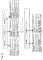
- FIG. 21 is a view showing a data structure in the case when program management information has an extended information area.
- the management information of a given program (program 1) is recorded in the forms of the general information of the program 1, the AV data designation information of the program 1 and the extended information of the program 1.
- the extended information in this case is available as detailed program information (genre, cast, description of contents, etc.) obtained from EPG, recording setting (setting of recording bit rate and the like) in the case of self-recording, actual data of a still image (thumbnail) indicating one scene of the program, a file name in the case when said thumbnail is used as an external file, setting as a reproduction prohibition program, setting as a candidate for an automatic deletion program, recording of information indicating that contents are those recorded automatically by an apparatus, information indicating the user who carried out recording, etc. Furthermore, in the case when one program is deleted, the management information of the program is also deleted simultaneously, whereby its extended information is also deleted.
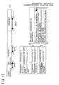
- FIG. 22 is a view showing a data structure in the case when Entry Point management information has an extended information area.
- Entry Point type information indicating the presence or absence of extended information, information specifying a position in the program and the extended information are recorded as Entry Point management information.
- the extended information is available as information indicating the change point of PSI/SI, information indicating data carousel start point, information indicating the in-point to CM, information indicating the out-point from CM, special event information (designation of jumping to another reproduction position, startup of external application on a PC, startup of HTML from an embedded URL, etc.), links (DCF objects, JPEG thumbnails, etc.) to related external files and the reproduction conditions (reproduction time and the like) of the external files, etc.
- the position of the Entry Point management information may be Cell management information or AV data management information. In this case, however, the position specifying information should only be able to designate a given position in the management information.
- the Entry Point type information may not be required.
- the Entry Point type may an item other than indicate the presence or absence of the extended information.
- FIG. 23 is a view showing a data structure in the case when Section Marker management information has an extended information area.
- Section Marker is information designating a given zone in a program by using two points, the start and end points, and the information is recorded in the program management information.
- Section Marker type information indicating the presence or absence of extended information, information specifying the start position of Section Marker in the program, information specifying the end position of Section Marker in the program and extended information are recorded as the Section Marker management information; and information indicating CM zones, information indicating the effective zones of data broadcasting, information indicating special effect areas, links (DCF objects, JPEG thumbnails, etc.) to related external files and the reproduction conditions (reproduction time and the like) of the external files, etc. can be recorded as the extended information.
- CM zones information indicating the effective zones of data broadcasting, information indicating special effect areas, links (DCF objects, JPEG thumbnails, etc.) to related external files and the reproduction conditions (reproduction time and the like) of the external files, etc.
- the position of the Section Marker management information may be Cell management information or AV data management information, instead of program management information.
- the position specifying information should only be able to designate a given position in the management information.
- the Section Marker type information may not be required.
- the Section Marker type may indicate an item other than the presence or absence of the extended information.
- FIG. 24 shows the basic data structure of the extended information.
- the extended information comprises IT_DATA_Ns indicating the number of pieces of the extended information and IT_DATA_SET indicating a set of extended information, and IT_DATA_SET comprises IT_DATA_Header and IT_DATA_Body, the number of which is designated by IT_DATA_Ns.
- IT_DATA_Header Extension ID (including common Extension ID being common in all apparatus makers) used to identify an apparatus maker, the type of the extended information, etc. and IT_DATA_Body_Size indicating the size of IT_DATA_Body are recorded.
- IT_DATA_Body comprises IT_TY_SZ indicating the type and size of DATA, and DATA serving as the main body of the extended information, these being used in a pair, in which such information as shown in FIG. 24 is recorded.
- the examples of the information are the title of the program, cast, producer, broadcasting station, genre, recording date and time, recording source, other additional information, program content information, names of external files, URL (these are common in common Extension ID and inherent Extension ID) , extended information (in the case when inherent Extension ID is used) being original to apparatus maker, etc. These types are designated by IT_TY, and the size of each piece of DATA is designated by IT_SZ.
- the broadcasting station, genre, recording data and time, recording source, etc., taken as the above-mentioned examples, may be constant, regardless of IT_SZ.
- FIG. 25 is a view showing a data structure in the case (FIG. 25 (a)) when link information to external extended information is recorded in extended information.
- FIG. 25 (b) an external extended information file name designating the file name of an external extended information file and an extended information start address and an extended information end address indicating offset addresses in the file are recorded in the external extended information link information.
- FIG. 26 is a view showing another data structure in the case when link information to external extended information is recorded in extended information.
- an external extended information file name designating the file name of an external extended information file and an extended information start address indicating an offset address in the file and extended information size indicating the size of the extended information are recorded in external extended information link information.
- an external extended information file name designating the file name of an external extended information file and extended information index number indicating the index number of the extended information from the head of the file are recorded in the external extended information link information.
- the size of a piece of extended information may be fixed, a search pointer corresponding to each index number may be present at the head of the external extended information file, and at the head of each piece of external extended information in the external extended information file, the size of the information itself may be recorded so that the address of the external extended information corresponding to the index number can be calculated
- the external extended information can be designated and may have any form.
- FIG. 53 shows an example of the configuration of the external extended information file illustrated in FIGS. 25 and 26.
- APP1 application data segment 1 included in a recorded DCF Basic file is stored.
- APP1 is recorded from the head of the logical sector; in the case when the end of APP1 does not coincide with the end of the logical sector, padding data is recorded therebetween. Any value may be used as the padding data.
- This APP1 includes metadata, such as photographing time, aperture value, etc.
- a thumbnail image of 160 pixels x 120 pixels is included definitely.
- APP1 is also referred to as Exif annexed information.
- the external extended information file shown in FIG. 53 is made reference to by Entry Point of FIG. 22 shown in the first embodiment and third, fourth or sixth embodiment described later or Section Marker of FIG. 23.
- the extended information in this Entry Point or the extended information in the Section Marker includes the external extended information link information shown in FIG. 25 or FIG. 26, and the external extended information link information includes the file name of the external extended information file shown in FIG. 53 as the external extended information file name.
- the external extended information link information has an extended information start address
- an offset address up to the head of APP1 in the file is stored.
- the identification number of the APP1 in the file is stored.
- FIG. 54 shows the data of the head portion of a DCF Basic file.
- the head portion of the DCF Basic file begins in the sequence of SOI (Start Of Image) and APP1.
- SOI is formed of only an SOI marker (OxFFD8).
- the contents of the APP1 are recorded in the sequence of an APP1 marker (OxFFE1), the data size of APP1 (excluding the data size of the APP1 marker) and the contents of the APP1.
- the maximum value of the data length field of the APP1 is 65535.
- FIG. 56 shows the detailed data structure of a DCF Basic file 321.
- the DCF Basic file 321 comprises SOI322, APP1 (323), JPEG-compressed DCF Basic Primary image (324) and EOI (End Of Image) 325.
- APP1 (323) comprises annexed information 326 mainly relating to DCF Basic Primary image and the thumbnail data 327 of the DCF Basic Primary image 324.
- the annexed information 326 relating to DCF Basic Primary image comprises 0th IFD, EXif IFD, Int. IFD (interoperability IFD) and 1st IFD.
- the thumbnail data 327 comprises SOI, JPEG-compressed thumbnail images and EOI.
- 0th IFD includes image resolution and the like.
- EXif IFD includes an aperture value, shutter speed value, maker note, comment, etc.
- the maker note is a field that can be set originally by the maker.
- Each IFD is formed of a common data structure referred to as a tag.
- the DCF Basic file 321 is a subset obtained by limiting the EXif image file.
- FIG. 57 shows the detailed data structure of a TIFF file 331 conforming to the EXif standard.
- the TIFF file 331 comprises a TIFF header 332, annexed information 333 conforming to the EXif standard, thumbnail images (uncompressed) 334 and image data (uncompressed) 355.
- the annexed information 333 conforming to the EXif standard comprises 0th IFD, EXif IFD, Int. IFD and 1st IFD, just as in the case shown in FIG. 56.
- the TIFF file 331 is treated as a DCF extended image file.
- the recording of a DCF thumbnail file 336 is recommended.
- the DCF thumbnail file 336 comprises SOI 337, APP1 (however, record option) 338, JPEG-compressed thumbnail images 339 and EOI 340.
- APP1 (338) includes 0th IFD, EXif IFD, Int. IFD and 1st IFD, serving as annexed information conforming to the EXif standard.
- FIG. 58 shows the physical locations of data on the DVD-RAM disk 315.
- the external extended information file is recorded in the area 309 on the inner circumference side, and the DCF Basic file 321 or the DCF extended image file 331 is recorded in the area 310 on the outer circumference side. It is assumed that the area 309 on the inner circumference side has been reserved as a recording area in which the external extended information file is recorded by a recorder in advance.
- the area 310 on the outer circumference side is a user area in which data used by the user, such as the DCF Basic file 321, the DCF extended image file 331 and other animated image data, is recorded.
- the area 309 on the inner circumference side is a management area in which management information for managing data recorded in the area 310 on the outer circumference side is recorded.
- FIG. 59 shows a DVD-RAM disk 315 on which the DCF Basic files 321 are recorded.
- the left side on the page corresponds to the inner circumference side of the DVD-RAM disk 315
- the right side corresponds to the outer circumference side of the DVD-RAM disk 315.
- the annexed information portion of each DCF Basic file 321 is recorded in the area 309 on the inner circumference side
- the DCF Basic file 321 comprising annexed information and compressed data is recorded in the area 310 on the outer circumference side of the DVD-RAM disk 315.
- the DCF Basic file 321 is recorded in the area 310 on the outer circumference side of the DVD-RAM disk 315, and the copy of the annexed information is recorded in the area 309 on the inner circumference side of the DVD-RAM disk 315.
- the compressed data in FIG. 59 (a) corresponds to the DCF Basic Primary image 324 and EOI (325) of FIG. 56.
- the annexed information corresponds to APP1 (323) and SOI (322) of FIG. 56.
- the annexed information (311b) and compressed data 311c have been recorded in the area 310 on the outer circumference side of the DVD-RAM disk 315, and annexed information (311a), that is, the copy of the annexed information (311b), has been recorded in the area 309 on the inner circumference side of the DVD-RAM disk 315.
- Thumbnail display by using the DVD-RAM disk 315 is carried out by only sequentially reading the annexed information (311a), the annexed information (312a) and the annexed information (313a) stored in the area 309 on the inner circumference side of the DVD-RAM disk 315 in the direction from the inner circumference side to the outer circumference side of the disk, for example.
- long-time seek operation in the case of the conventional DVD-RAM disk 301 shown in FIG. 62 does not generate.
- thumbnail display can be attained quickly even if large amounts of the DCF Basic files 321 have been recorded on the DVD-RAM disk 315.
- each piece of the annexed information can be accessed by fewer seek operations, whereby the retrieval can be attained quickly.
- FIG. 59 (b) shows the operation in the case when the still images of the DCF Basic files 321 are displayed.
- the still images of the DCF Basic files 321 it is necessary to access both the annexed information and compressed data constituting the DCF Basic file 321.
- the annexed information (311b) and compressed data 311c recorded in the area 310 on the outer circumference side of the DVD-RAM disk 315 are accessed.
- the annexed information stored in the area 309 on the inner circumference side of the DVD-RAM disk 315 is not accessed.
- the whole of the APP1 (323) or the excerpt information thereof is recorded, for example.
- the excerpt information of the APP1 (323) is recorded, information excluding the APP1 marker shown in FIG. 54 or information further excluding the APP1 data length is recorded, for example.
- recording may be carried out in the area 309 on the inner circumference side of the DVD-RAM disk 315 by using SOI and APP1 shown in FIG. 54 as units, or recording may also be carried out by using only the APP1 as a unit, or recording may also be carried out by using the portion obtained by excluding the first two bytes (APP1 marker) from APP1 as a unit, or recording may also be carried out by using the portion obtained by excluding the first four bytes (APP1 marker and APP1 data length) from APP1 as a unit.
- the data size may be recorded separately.
- At least the copies of thumbnail images or the copies of retrieval information for retrieving image information should only be recorded in the area 309 on the inner circumference side of the DVD-RAM disk 315.
- the DCF Primary image 324 in accordance with this embodiment is an example of image information in accordance with the present invention
- the area 309 on the inner circumference side in accordance with this embodiment is an example of the second area in accordance with the present invention
- the area 310 on'the outer circumference side in accordance with this embodiment is an example of the first area in accordance with the present invention.
- a thumbnail file is read in advance and placed on the memory, and index display is carried out quickly by using the thumbnail data on the memory. Since the data amount of the thumbnail data is about 8 KBytes for one piece, many thumbnails can be placed on the memory. Furthermore, even in the case when the total of the still images is large and when all of the thumbnail data cannot be placed on the memory, if annexed information is arranged in the sequence of recording, by carrying out display while sequentially reading the external extended information files in the sequence of recording, display can be carried out quickly in comparison with the case wherein the thumbnail data on the outer circumference side is read.
- the APP1s generated at the time of recording the DCF Basic files can be directly recorded in external extended information file in accordance with the first embodiment, whereby external extended information can be created easily.
- the sequence of the recording can be stored similarly by recording Entry Point or Section Marker.
- the DCF Basic files having been recorded in a memory card can be stored on the DVD-RAM disk 315 via the memory card interface 354.
- the sequence of the recording can be stored similarly by recording Entry Point or Section Marker.
- the external extended information file generation section 352 of the recorder (the DVD camcorder 350) reads the first six bytes of the DCF Basic file having been received and recorded, detects the data size of APP1 recorded at the last two bytes, reads its data portion, and copies the whole of the APP1 portion having been read as the result to the inside of the external extended information file. Then, external extended information link information is recorded inside the extended information of Entry Point or Section Marker.
- thumbnail data can be additionally recorded easily into the external extended information file.
- image index display can be carried out quickly by using the thumbnail images recorded in APP1.
- both of the metadata and thumbnail data are stored in one external extended information file; however, either of them may be stored.
- APP1 included in the DCF Basic file having been outside-recorded is directly stored in the external extended information file; however, in the case when the data size of APP1 is too large, part thereof may be extracted and then stored. However, even in this case, the internal data structure of APP1 should conform to the DCF standard. For example, in the case when the data size of the maker note field (maker note tag) in Exif IFD of APP1 is larger than a predetermined data size, this field is omitted or subjected to other processing.
- APP1 is directly copied and stored into the external extended information file; however, the thumbnail data may be separated from metadata inside APP1, and separate external extended information files may be created, and reference may be carried out from Entry Point or Section Marker.
- the thumbnail data may be separated from metadata inside APP1, and separate external extended information files may be created, and reference may be carried out from Entry Point or Section Marker.
- more detailed internal data structure analysis of APP1 is required.
- thumbnail data is extracted from the inside of APP1 to generate compact metadata, it is necessary to consider recalculation of metadata value expression types (eight types: BYTE, ASCII, SHORT, LONG, RATIONAL, UNDEFINED, SLOG and SRATIONAL) and pointer information, whereby processing becomes complicated.
- thumbnail data is separated from the metadata, they may be included in one file, instead of being included in separate external extended information files.
- thumbnail data and metadata regarding other still image files may be stored in the extended information file.
- a DCF extended image file may be included.
- the DCF thumbnail file recorded simultaneously with the DCF extended image file may be directly stored as thumbnail data in the external extended information file.
- the DCF thumbnail file does not necessarily include metadata (annexed information conforming to the Exif standard) owing to the regulations of the DCF standard.
- metadata it is necessary to add metadata so that APP1 becomes similar to that in the case of the DCF Basic file.
- a DCF extended image file is a TIFF file conforming to the Exif standard
- metadata conforming to the Exif standard is stored in the TIFF file, whereby the copy of this data may be added.
- a TIFF file conforming to the Exif standard may be included.
- annexed information stipulated by the Exif standard is included in the TIFF file.
- the copy of this annexed information may be stored in the external extended information file.
- the thumbnail data is not necessarily be included in the TIFF file owing to the regulations of the Exif standard.
- the thumbnail data included in the TIFF file is determined to be uncompressed wing to the regulations of the Exif standard.
- the thumbnail data of animated images may be mixed with the thumbnail data of a still image file to form one external extended information file.
- the metadata of animated images may be mixed with the metadata of a still image file to form one external extended information file.
- APP1 is stored in an external extended information file made reference to from Entry Point or Section Marker
- other data may be made reference to, instead of files made reference to from Entry Point or Section Marker.
- APP1 is stored in an external extended information file, it is not necessary to include an APP1 marker and an APP1 data length.
- FIG. 27 is a view showing the data structure of an extended information ID (Extension ID).
- the extended information ID has a character string representing external extension; it is assumed that the range of data just before the string end code is effective data. Furthermore, in FIG. 27 (b), the extended information ID designates a character string representing external extension; a conversion table of the designated ID and the character string representing external extension is provided separately, and the extension information can be represented by referring to the conversion table.
- FIGS. 28 and 29 are views showing data structures with respect to the descriptions of an extended information set (IT_DATA_SET).
- the figures show the details and other forms of the structure explained in FIG. 24. It is assumed that any of the data structures illustrated in FIGS. 28 (a), 28 (b), 29 (a) and 29 (b) may be used.
- FIG. 30 shows extended information sub_ID and extended information copyright information in extended information
- the extended information sub_ID indicates extended information type identification information shown in FIG. 30 (a).
- the extended information copyright information in FIG. 30 (a) is information recorded for copyright protection as shown in FIG. 30 (b).
- FIG. 31 is a view showing a data structure in the case when the extended information area of program management information has a pointer to a thumbnail.
- "FILE NAME” representing an external file name is selected as IT_TY of the extended information
- "MEI/s0001.JPG” serving as the still image file name of one scene of program 1 for example is recorded as DATA.
- a directory for each apparatus maker may be created in the VIDEO_RT directory (FIG. 31). This can solve problems due to overlapping of file names among apparatus makers.
- FIG. 32 is a view showing a data structure in the case when the Entry Point extended information area is provided with pointers to thumbnail data.
- a program selection menu screen as shown in FIG. 32 can be created.
- a directory for each apparatus maker may be created in the VIDEO_RT directory (FIG. 32). This can solve problems due to overlapping of file names among apparatus makers.
- FIG. 33 is a view showing a data structure in the case when a still image display zone is recorded in the Section Marker management information (a Section Marker designating a still image display zone in this way is hereafter referred to as a Still Section Marker).
- FIG. 34 is a view showing the state of display in the case when the program shown in FIG. 33 is reproduced.
- sequence information of photographing by the user can be stored; during reproduction, not only the respective reproduction of animated images and still images but also the reproduction of the sequence of their recording can be carried out.
- the name of the directory in which the still image files are stored for example, a DCF directory name
- the still image files under the designated directory are reproduced sequentially.
- the reproduction time information of each still image file or the total reproduction time information of all the files under the directory may be stored in the extended information of Still Section Marker.
- the reference information to the external extended information file in which the list of the names of still image files are stored, may be recorded in the extended information of Still Section Marker.
- the list of still image file names and directory names to be displayed may be stored in the external extended information of the external extended information file shown in FIG. 25 or 26.
- information regarding the reproduction times of still image files may also be stored in the external extended information file.
- the information to be stored in the extension information of Still Section Marker is similar to that used in the following embodiments.
- FIG. 35 is a view illustrating another display example of Still Section Marker.
- FIG. 35 (a) information specifying the start position of SM in a program and information specifying the end position of SM in the program are recorded to specify the display positions of Still Section Markers, and FIG. 35 (b) shows the state of the display of the program.
- Both of the methods shown in FIGS. 33 and 35 may be used to specify the display position of Still Section Markers.
- loop 1 from step 501 to step 505 is carried out from the start of recording operation to the end of the recording.
- a recording object is generated by a recording apparatus (at step 502), and the recording object is recorded (at step 503).
- object information and time map information for the object generated at step 502 are generated (at step 504).
- reproduction path information is generated and recorded (at step 507).
- Section Marker information is generated and recorded in the zone wherein recording is carried out (at step 508), whereby the recording operation is ended.
- Still Section Markers are generated and recorded at step 508. Still Section Markers are generated so that a program is reproduced in the sequence wherein animated images and still images are recorded.
- the generation may be carried out in a desired different reproduction sequence at the time of later reproduction in the case when the user or system intends to do so.
- Section Marker information may be generated and recorded at desired timing.
- Section Marker information may not be recorded during recording operation.
- FIG. 37 A method of reproducing a program to which Section Markers shown in FIG. 33 are added will be explained by using the flowchart shown in FIG. 37.
- the reproduction path information recorded on the disk is read (at step 601).
- data to be reproduced is selected (at step 602), and the time map information of the target data determined at step 602 is read (at step 603), and the Section Marker information is read (at step 604).
- loop 1 from step 605 to step 609 is carried out.
- the object to be reproduced is read (at step 606).
- the reproducing apparatus corresponds to the Section Marker ID
- Section Markers are Still Section Markers
- the corresponding still images are read and reproduced (at step 612).
- extended information is executed (at step 613), and reproduction is carried out (at step 608).
- the reproducing apparatus corresponds to the Section Marker ID at step 610, only reproduction is carried out (at step 608). After all of data to be reproduced are reproduced, the loop 1 is ended, whereby reproduction operation is ended.
- FIG. 38 is a view illustrating a method of recording a program including only still images by using Still Section Markers.
- a main part not including actual reproduction image data is set in the program, and the reproduction time of the main part is set at 0, whereby a program including only still images is formed.
- FIG. 39 is a view illustrating a method of recording a user-defined program to which the Still Section Markers shown in FIG. 33 are added.
- the user-defined program can have a configuration wherein reproduction starts or stops in the middle of the display time of still images in the program.
- FIGS. 39 to 44 A third embodiment in accordance with the present invention will be described below by using FIGS. 39 to 44.
- a difference may occur in some cases in the display time of a program between a reproducing apparatus conforming to still images and a reproducing apparatus not conforming to still images as shown in FIG. 40.
- the display time becomes the same even in the case of the reproducing apparatus not conforming to still images.
- FIG. 41 is a view illustrating a method wherein a Still Section Marker is provided during recording of each still image and data obtained by MPEG-encoding the same image as the still image is recorded in the main part corresponding to the display period of the still image.
- FIG. 42 is a view illustrating display in the case when the program to which Still Section Markers shown in FIG. 41 are added is processed in accordance with the flowchart shown in FIG. 37.
- FIG. 42 (a) is a view in the case when the program to which Still Section Markers are added is reproduced by the reproducing apparatus conforming to still image display
- FIG. 42 (b) is a view in the case when the program to which Still Section Markers are added is reproduced by the reproducing apparatus not conforming to still image display.
- the reproducing apparatus conforming to still images and the reproducing apparatus not conforming to still images can have the same program display time, whereby the user is not confused even when reproduction environment is different.
- FIG. 43 is a view illustrating the case when a program including only still images is recorded by using Still Section Markers. Also in this example, just as in the case shown in FIG. 41, a program including only still images is formed by the method wherein a Still Section Marker is provided during recording of each still image and data obtained by MPEG-encoding the same image as the still image is recorded in the main part corresponding to the display period of the still image.
- the reproducing apparatus conforming to still images and the reproducing apparatus not conforming to still images can have the same program display time; furthermore, even in the case when the setting of the main parts is essential in the formation of a program, a program including only still images can be formed without preparing special dummy data.
- the reproducing apparatus not conforming to still images can reproduce a program including only still images, except that reproduction quality is low; hence, the user is not confused even when reproduction environment is different.
- the image when the same image as a still image is MPEG-encoded in a main part, the image may be encoded at a resolution higher than those in other main parts.
- encoding may be carried out at high definition (HD) in the still image zone.
- HD high definition
- FIG. 44 is a view illustrating a method of recording a user-defined program in the case when the program is a program to which Still Section Markers shown in FIG. 41 are added.
- the user-defined program can have a configuration wherein reproduction starts or stops in the middle of the display time of still images in the program.
- the reproducing apparatus conforming to still images and the reproducing apparatus not conforming to still images can have the same program display time, even in the case of this user-defined program 1.
- FIGS. 45 to 48 A fourth embodiment in accordance with the present invention will be described below by using FIGS. 45 to 48.
- FIG. 45 is a view illustrating a method wherein Still Section Markers are set during recording of still images and information for referring to special data is recorded in program management information in the zone corresponding to a still image display period.
- the special data in FIG. 45 is data having a reproduction time sufficiently longer than the duration time designated by the Still Section Marker.
- all of the special data made reference to by the program management information may be the same data, or respectively different data may also be made reference to. By sharing the same data, the amount of data to be recorded on the disk can be reduced.
- the special data may be stored in a file different from the file in which program data is stored.
- FIG. 46 is a view illustrating display in the case when the program to which Still Section Markers shown in FIG. 45 are added is processed in accordance with the flowchart shown in FIG. 37.
- FIG. 46 (a) is a view in the case when the program to which Still Section Markers are added is reproduced by the reproducing apparatus conforming to still image display
- FIG. 46 (b) is a view in the case when the program to which Still Section Markers are added is reproduced by the reproducing apparatus not conforming to still image display.
- a still image file designated by Still Section Markers is displayed in the periods designated of Still Section Markers; however, in FIG. 46 (b), the decoded contents of the special data are displayed during the still image display periods designated by Still Section Markers.
- the reproducing apparatus conforming to still images and the reproducing apparatus not conforming to still images can have the same program display time.
- the special data may be data obtained by MPEG-encoding error messages or blue back indicating that still image data is corresponded to this zone.
- FIG. 47 is a view illustrating the case when a program including only still images is recorded by using Still Section Markers. Also in this example, just as in the case shown in FIG. 45, a program including only still images is formed by the method wherein a Still Section Marker is set during recording of each still image and special data is recorded in the main part corresponding to the display period of the still image.
- the reproducing apparatus conforming to still images and the reproducing apparatus not conforming to still images can have the same program display time.
- FIG. 48 is a view illustrating a method of recording a user-defined program in the case when the program is a program to which Still Section Markers shown in FIG. 45 are added.
- the user-defined program can have a configuration wherein reproduction starts or stops in the middle of the display time of still images in the program.
- the reproducing apparatus conforming to still images and the reproducing apparatus not conforming to still images can have the same program display time, even in the case of this user-defined program 1.
- FIGS. 49 to 50 A fifth embodiment in accordance with the present invention will be described below by using FIGS. 49 to 50.
- FIG. 49 is a view illustrating a Still Section Marker, in the extended information of which overlay attribute information in addition to a still image file name is described.
- the overlay attribute information shown in FIG. 49 has the presence/absence of an overlay instruction, an overlay instruction, etc.
- a reproducing apparatus conforming to overlay can display a still image external file while a designated overlay method is carried out in still image display zones wherein Still Section Markers are set.
- FIG. 50 is a view illustrating the display at the time when the data shown in FIG. 49 is displayed.
- FIG. 50 (a) is a display at the time when data to which Section Markers having the overlay attribute information as shown in FIG. 49 is added is reproduced by an apparatus conforming to overlay
- 50 (b) is a display at the time when data to which no Section Marker is added in FIG. 49 is reproduced.
- a still image is displayed while the overlay instruction contents in the overlay attribute information are carried out at the portion wherein main part 2 is displayed.
- the contents of the overlay instruction at this time are the designation of sound reproduction/non-reproduction of main parts, the designation of still image location information (centering, moving upward, etc.), the designation of still image scaling information (reduction to 80% or the like), the designation of main part image displaying/non-displaying in the remaining area at the time when the still image is subjected to scaling down or centering, the designation of transition effects, etc.
- Section Markers are set for the main parts, they may also be set at the periods corresponding to the main parts 1'/2' shown in FIGS. 41 and 45 (the periods during which still images are MPEG-encoded and recorded or the recording periods of the special data).
- FIGS. 51 and 52 A sixth embodiment in accordance with the present invention will be described below by using FIGS. 51 and 52.
- FIG. 51 is a view showing another structure of the Section Marker; unlike the structure shown in FIG. 23, the pointer to the thumbnail data corresponding to the Section Marker is held as a common data structure.
- the pointer information to thumbnail data shown in FIG. 51 has the name of an external file serving as still images, just as explained in FIGS. 31 and 32.
- still image external files made reference to as thumbnail data instead of still image files, can be displayed.
- the information to the pointer to thumbnail data may be the external extended information file explained in FIGS. 25 and 26; in this case, each piece of thumbnail data is stored as each piece of external extended information in the external extended information file.
- the pointer to the thumbnail data corresponding to Entry Point may have a common data structure.
- FIG. 52 shows the data structure obtained at this time.
- the format of the extended information in accordance with the embodiments is not limited to those explained by using FIGS. 24, 28, 29, etc., but the format may have a predetermined data structure corresponding to the type information of Entry Point and Section Marker.
- the Entry Point type information indicates that its Entry Points correspond to still image reproduction zones
- position specifying information in the program indicates the start positions of the still image reproduction zones
- reference information to still image files and the reproduction times of the still image files are stored in the extended information.
- data obtained by MPEG-encoding the same image as the still image in the main part corresponding to the still image display period may be recorded, information for making reference to special data may recorded in the management information of the program, or nothing particular may be recorded.
- DVD-RAM disk is taken as an information recording medium in the embodiments described above, other optical disks, hard disk drives, other magnetic recording media, semiconductor memories, etc. may also be used instead of the DVD-RAM disk.
- the reproduction time for the program can be made identical regardless of the conformity/nonconformity of the reproducing apparatus to the still images. Furthermore, in the case when data obtained by MPEG-encoding an error message indicating that still image data is related thereto is recorded in this zone, a notification that the zone is a zone wherein still images should be reproduced can be given to the user who reproduced the program by using the reproducing apparatus not conforming to still images.
- overlay of a still image on the main part of the program can be attained.
- the program in accordance with the present invention is a program that carries out the functions of all or part of the means (or apparatuses, devices, etc.) of the above-mentioned recording apparatus of the present invention by using a computer and operates in cooperation with the computer.
- the program in accordance with the present invention is a program that carries out the functions of all or part of the means (or apparatuses, devices, etc.) of the above-mentioned reproducing apparatus of the present invention by using a computer and operates in cooperation with the computer.
- the recording medium of the present invention is a recording medium having a program that carries out all or part of the functions of all or part of the means (or apparatuses, devices, etc.) of the above-mentioned recording apparatus of the present invention by using a computer, the medium is readable by the computer, and said program having been read is used to carry out the above-mentioned functions in cooperation with the above-mentioned computer.
- the recording medium of the present invention is a recording medium having a program that carries out all or part of the functions of all or part of the means (or apparatuses, devices, etc.) of said reproducing apparatus of the present invention by using a computer, the medium is readable by the computer and said program having been read is used to carry out said functions in cooperation with said computer.
- the above-mentioned “the functions of the means (or apparatuses, devices, etc.)” of the present invention are all or part of the functions of said means, and the above-mentioned “the operations of the steps (or processes, operations, actions, etc.)" of the present invention are all or part of said steps.
- one utilization form of the program of the present invention may be an embodiment that is recorded on a recording medium readable by a computer and operates in cooperation with the computer.
- another utilization form of the program of the present invention may be an embodiment that is transmitted through a transmission medium, is read by a computer and operates in cooperation with the computer.
- the data structure of the present invention includes database, data format, data table, data list, data type, etc.
- the recording medium includes ROM and the like
- the transmission medium includes a transmission medium, such as the Internet, light, electric wave, sound wave, etc.
- the above-mentioned computer in accordance with the present invention is not limited to pure hardware, such as a CPU, but may include firmware, OS and peripheral devices.
- the configuration of the present invention may be attained by software or by hardware.
- the present invention can provide a recording medium capable of increasing the processing speed at the time when still images are retrieved by designating aperture, shutter speed, etc. during recording.
- the present invention can provide a recording medium capable of increasing the speed of displaying the indexes of thumbnails.
- the present invention can provide a recording medium capable of increasing the speed of importing still image files.
- the present invention can provide a recording medium capable of increasing the speed of displaying still image files.
- the present invention can provide a recording medium capable of attaining smooth coordinated reproduction of animated image data and still image data recorded on a DVD-RAM disk.
- the present invention can provide a recording medium capable of attaining the reproduction of AV data without confusing the user even in the case when the coordinated reproduction of animated image data and still image data is carried out by using an apparatus other than that used for recording.
Landscapes
- Engineering & Computer Science (AREA)
- Signal Processing (AREA)
- Multimedia (AREA)
- Television Signal Processing For Recording (AREA)
- Signal Processing For Digital Recording And Reproducing (AREA)
- Management Or Editing Of Information On Record Carriers (AREA)
Abstract
Extended information capable of defining the
reproduction sequence of still images is provided in
the management information of program information for
defining the reproduction sequence of animated images
recorded on an information recording medium, whereby a
program in which animated images and still images are
mixed is attained. Recording of a program including
only still images is attained, and a user-defined
program in which the user defines reproduction
sequence for the program including mixed still images
is also attained.
When still images are recorded, Section Markers
in which the display periods of the still images, the
file names of the still images, etc. can be described
are set in the management information of the program.
When still images are recorded, the same still
images as the still images are MPEG-encoded and
recorded, just like animated image data, and Section
Markers in which the display periods of the still
images, the file names of the still images, etc. can
be described are set in the management information of
the program.
Description
The present invention relates to a
readable/writable recording medium and more
particularly to a recording medium on which multimedia
data including data having various formats, such as
animated image data, still image data, audio data and
data for data broadcasting, is recorded.
In the field of rewritable optical disks having
an upper limit capacity of about 650 MB, a phase-change
disk DVD-RAM having a capacity of several
GBytes has been developed. Combined with the
practical use of MPEG (MPEG2) used as a digital AV
data coding standard, the DVD-RAM is expected to be a
recording/reproducing medium not only for computers
but also for the audio/video (AV) technical field.
A DVD disk, DVD recorder and DVD player, that is,
embodiments of a conventional information recording
medium, recording apparatus and reproducing apparatus,
will be described below in the following sequence. 1.
General description of the system of the DVD recorder
apparatus; 2. General description of the functions of
the DVD recorder apparatus; 3. General description of
the DVD disk; 4. General description of AV information
to be reproduced; 5. General description of management
information and reproduction control for AV
information; 6. Basic operations of reproduction
function; and 7. Basic operations of recording
function (1. General description of the system of the
DVD recorder apparatus)
FIG. 1 is a view illustrating the outer
appearance of a DVD recorder apparatus and an example
of an interface between the DVD recorder apparatus and
related apparatuses. As shown in FIG. 1, a DVD disk
serving as an optical disk is loaded into the DVD
recorder, and video information is recorded/reproduced.
The operations are generally carried out by remote
control.
Both analog and digital signals are available as
video information to be input to the DVD recorder;
analog broadcasting is available as analog signals,
and digital broadcasting is available as digital
signals. Generally, analog broadcasting is received
and demodulated by a receiver built in a TV set and
input to the DVD recorder as an analog video signal of
NTSC or the like; and digital broadcasting is
demodulated by an STB (Set Top Box) serving as a
receiver to a digital signal and input to the DVD
recorder and recorded.
On the other hand, video information recorded on
a DVD disk is reproduced by the DVD recorder and
output to the outside. Both analog and digital
signals are also available for output, just as in the
case of input; the analog signal is directly input to
a TV set, and the digital signal passes through the
STB, is converted into an analog signal, input to the
TV set and displayed on the TV set as images.
Furthermore, in some cases, video information is
recorded/reproduced on a DVD disk by a DVD camcorder
or a personal computer, other than the DVD recorder.
Even in the case of a DVD disk on which video
information has been recorded by an apparatus other
than the DVD recorder, when it is loaded into the DVD
recorder, it is played back by the DVD recorder.
The video information of the above-mentioned
analog broadcasting and digital broadcasting is
usually accompanied by audio information. The
accompanied audio information is also
recorded/reproduced by the DVD recorder similarly.
Although video information is generally formed of
animated images, the information may be formed of
still images in some cases. For example, this applies
to the case wherein still images are recorded by the
photographing functions of a DVD camcorder.
The digital I/F between an external apparatus,
such as the DVD recorder and the STB, can be IEEE1394,
ATAPI, SCSI, USB, Ethernet, etc.
Although NTSC, that is, a composite video signal,
is exemplified as a signal used between the DVD
recorder and the TV set, component signals for
individually transmitting a luminance signal and color
difference signals may be used. Furthermore, research
and development is being promoted to replace an analog
I/F for the video transition I/F between an AV
apparatus and a TV set with a digital I/F, such as DVI,
whereby it is naturally expected that the DVD recorder
can be connected to the TV set via a digital I/F.
(2. General description of the functions of the DVD recorder apparatus)
(2. General description of the functions of the DVD recorder apparatus)
FIG. 2 is a block diagram showing the functions
of the DVD recorder apparatus. The drive apparatus
thereof comprises an optical pickup 101 that reads the
data of a DVD-RAM disk 100, an ECC (Error Correcting
Code) processing section 102, a track buffer 103, a
switch 104 that switches the input/output of the track
buffer 103, an encoder section 105 and a decoder
section 106. As shown in the figure, data is recorded
on the DVD-RAM disk 100 by using 1 sector = 2 KB as
the minimum unit. In addition, the ECC processing
section 102 carries out error correction processing by
using one ECC block as a unit, that is, 16 sectors = 1
ECC block.
The DVD recorder apparatus may be provided with a
semiconductor memory card and a hard disk drive
apparatus as a data storage medium, in addition to the
DVD-RAM disk. FIG. 4 is a block diagram showing a DVD
recorder provided with a semiconductor memory card and
a hard disk drive apparatus. One sector may have 512
B, 8 KB, etc. Furthermore, the ECC block may have 1
sector, 16 sectors, 32 sectors, etc. It is expected
that the size of the sector and the number of sectors
constituting the ECC block increase as the amount of
recordable information increases.
The track buffer 103 is a buffer that is used to
record AV data at a variable bit rate (VBR) so that
the AV data is more efficiently recorded on the DVD-RAM
disk 100. Although the read/write rate (Va) to
the DVD-RAM disk 100 is a fixed rate, since the bit
rate (Vb) changes depending on the complexity of the
contents (images in the case of a video signal) of the
data, the buffer is used to absorb the difference in
this bit rate.
By further effectively using this track buffer
103, the AV data can be scatteringly located on the
DVD-RAM disk 100. This will be described by using FIG.
3. FIG. 3 (a) is a view showing address space on the
disk. In the case when AV data is separately recorded
in a continuous area of [a1, a2] and a continuous area
of [a3, a4] as shown in FIG. 3 (a), while seek is
carried out from a2 to a3, by supplying the data
stored in the track buffer to the decoder section 106,
the AV data can be reproduced continuously. The
condition obtained at this time is shown in FIG. 3 (b).
The AV data started to be read at position a1 is
input to the track buffer 103 at time t1, and data
output from the track buffer 103 starts. Hence, the
amount of the data corresponding to the rate
difference (Va - Vb) between the rate (Va) of input to
the transfer buffer and the rate (Vb) of output from
the transfer buffer is begun to be stored. This
condition continues until the retrieval area a2 is
reached, that is, until time t2 is reached. When it
is assumed that the amount of the data stored in the
transfer buffer 103 in this period is B (t2), the
amount B (t2) stored in the transfer buffer 103 should
only be consumed and supplied continuously to the
decoder 106 in the period from time t2 to time t3 when
data reading from the area a3 starts.
In other words, if the amount of data ([a1, a2])
to be read before seek, having been obtained, is a
constant amount or more, even in the case when seek
has occurred, continuous supply of the AV data is
possible. The size of the continuous area wherein the
continuous supply of the AV data is possible is
represented by the following equation when converted
into the number of ECC blocks (N_ecc). In the
equation, N_sec is the number of sectors constituting
an ECC block, S_size is the size of a sector, and Tj
is seek performance (maximum seek time).
N_ecc = Vb*Tj/
((N_sec*8*S_size)*(1-Vb/Va))
In addition, a defective sector may occur in the
continuous area. When this case is considered, the
continuous area is represented by the following
equation. In the equation, dN_ecc is the size of an
allowable defective sector, and Ts is the time
required for skipping the defective sector in the
continuous area. This size is also represented by the
number of ECC blocks.
N_ecc = dN_ecc+Vb*(Tj+Ts)/
((N_sec*8*S_size)*(1-Vb/Va))
The case wherein data is read, namely, reproduced,
from a DVD-RAM disk has been explained herein as an
example; however, the case wherein data is written,
namely, recorded, onto the DVD-RAM disk can also be
considered similarly. As described above, if data
having a constant amount or more has been recorded
continuously on the DVD-RAM disk, continuous
reproduction/recording is possible even if AV data is
scatteringly recorded on the disk. This continuous
area on the DVD disk is referred to as CDA. (3.
General description of the DVD disk)
FIG. 5 is a view showing the outer appearance and
the physical structure of the DVD-RAM disk serving as
a recordable optical disk. The DVD-RAM disk is loaded
into a DVD recorder in a state of being generally
accommodated in a cartridge. This is done to protect
the recording face thereof. However, when the
protection of the recording face is done by another
configuration or when nonuse of the cartridge is
allowable, a configuration wherein the disk can be
directly loaded into the DVD recorder without being
accommodated in a cartridge is also possible as a
matter of course.
Data is recorded on the DVD-RAM disk by the
phase-change system. The data recorded on the disk is
managed in sector units and accompanied by access-use
addresses. Sixteen sectors become an error-correction
unit, and an error-correction code is attached
thereto; the sectors are referred to as an ECC block.
FIG. 5 (a) is a view showing the recording area
of a DVD-RAM disk serving as a recordable optical disk.
As shown in the figure, on the DVD-RAM disk, a lead-in
area is located in the innermost circumference thereof,
a lead-out area is located in the outermost
circumference thereof, and a data area is located
therebetween. In the lead-in area, reference signals
required for stabilizing servo control during the
access time of the optical pickup, signals for
discrimination from other media, etc. have been
recorded. Also in the lead-out area, reference
signals similar to those in the lead-in area and the
like are recorded. The data area is divided into
sectors (one sector has 2048 bytes), one sector being
the minimum access unit.
In addition, the data area of the DVD-RAM disk is
divided into plural zone areas to attain rotation
control referred to as Z-CLV (Zone Constant Linear
Velocity) during recording/reproduction.
FIG. 5 (a) is a view showing plural zone areas
provided concentrically on the DVD-RAM disk. As shown
in the figure, the DVD-RAM disk is divided into 24
zone areas, zone 0 to zone 23. The rotational angular
velocity of the DVD-RAM disk is set for each zone area
so that the velocity is higher as the zone is located
nearer to the inner interference side; the velocity is
maintained constant when the optical pickup gains
access in one zone. Hence, the recording density of
the DVD-RAM disk is raised, and rotation control
during recording/reproduction is made easy.
FIG. 5 (b) is a view in which the lead-in area,
the lead-out area and the zone areas 0 to 23 shown
concentrically in FIG. 5 (a) are illustrated in a
lateral direction. The lead-in area and the lead-out
area have a defect management area (DMA: Defect
Management Area) therein. The defect management area
is an area wherein position information indicating the
positions of sectors having defects and the
alternative position information indicating which of
the above-mentioned alternative areas have sectors
alternative to the defective sectors.
Each zone area has a user area therein and also
has an alternative area and an unused area at the
boundary section. The user area is an area that can
be used as a recording area by a file system. The
alternative area is an area that is used alternatively
when a defective sector is present. The unused area
is an area not used for data recording. About two
tracks are provided for the unused area. Although a
sector address is recorded at the same position as
those of the sector addresses on adjacent tracks in a
zone, since the recording positions of the sector
addresses on tracks adjacent to the boundary of the
zone are different in the Z-CLV system, the unused
area is provided to prevent improper discrimination of
sector addresses due to the difference.
As described above, sectors not used for data
recording are present in the zone boundaries. Hence,
on the DVD-RAM disk, logical sector numbers (LSN:
Logical Sector Number) are assigned to the physical
sectors of the user areas sequentially from the inner
circumference so that only the sectors for data
recording are indicated continuously.
FIG. 6 shows the logical data space of the DVD-RAM
disk formed of logical sectors. The logical data
space is referred to as a volume space in which user
data is recorded. In the volume area, recorded data
is controlled by the file system. In other words,
information for managing a group of sectors for data
storage as a file and information for managing a group
of files as a directory are recorded in partition
spaces in the volume space, and volume structure
information for managing partition spaces and the like
is recorded at the head and end of the volume area.
The file system in accordance with this embodiment is
referred to as UDF conforming to the ISO13346.
The sectors in the above-mentioned group of
sectors are not necessarily located continuously but
located partially scatteringly in the volume space.
Hence, among groups of sectors constituting files, the
file system manages a group of sectors located
continuously in the volume space as an extent and
manages a file as a set of extents.
FIG. 7 shows the structures of the directories
and files of animated image data recorded on the DVD-RAM
disk. Under the root, a VIDEO_RT directory is
present, and under this, the files of various objects
serving as data for reproduction and VIDEO Manager
files serving as management information indicating the
reproduction sequence and various attributes of these
are stored.
The objects are data conforming to the MPEG
standard and available as PS_VOB, TS1_VOB, TS2_VOB,
AOB, POB and MNF.
PS_VOB, AOB and POB are program streams (PS) of
MPEG, and TS1_VOB and TS2_VOB are transport streams
(TS). A program stream has a data structure formed in
consideration of storing AV information on a package
medium; on the other hand, a transport stream has a
data structure formed in consideration of
communication media.
Generally, each of PS_VOB, TS1_VOB and TS2_VOB is
an object having both video information and audio
information, and mainly composed of video information.
In principle, among these, TS1_VOB is an object that
is encoded by a DVD recorder and its internal picture
structure is managed minutely, and TS2_VOB is an
object that is encoded by an apparatus other than the
DVD recorder, and its data structure, such as its
internal picture structure, is partially unknown.
Typically, TS1_VOB is an object that is obtained
when an analog video signal input externally is
encoded to a transport stream by the DVD recorder, and
TS2_VOB is an object that is obtained when a digital
video signal input externally is directly recorded on
the disk without being encoded.
AOB and POB are program streams of MPEG; AOB is
an object mainly composed of audio information, and
POB is an object mainly composed of still images. MNF
is a file inherent to a manufacturer, and additional
information for supporting the operations of a
recording/reproducing apparatus is stored therein.
Not all of these PS_VOB, POB, AOB, TS1_VOB and
TS2_VOB are required to be recorded.
The fact that information is mainly composed of
video information or audio information described above
means that bit-rate assignment is large. VOB is used
for applications such as movies, and AOB is used for
music applications.
FIG. 20 shows the structure of the directories
and files of still image data to be recorded on the
DVD-RAM disk. The structure of directories and files
conforming to the DCF standard is taken as an example
and explained herein.
Under the root directory, a DCF image root
directory (directory name: DCIM) is present, and DCF
directories for image storage are present thereunder.
Under the DCF directory, DCF objects serving as
reproduction data are stored.
The DCF objects are a group of files recorded in
conformity with DCF and includes DCF Basic files, DCF
extended image files, DCF thumbnail files, etc.
The DCF Basic file is recorded directly under the
DCF directory, has a DCF file name and an extension
"JPG," conforms to the Exif standard and is an image
file having the data structure determined by the DCF
standard.
The DCF extended image file is recorded directly
under the DCF directory and has a DCF file name, but
is an image file having an extension and a data
structure different from those of the DCF Basic file.
The DCF thumbnail file is a compressed file for
recording the thumbnails of the DCF extended image
file.
Not all the DCF Basic files, DCF extended image
files and DCF thumbnail files are required to be
recorded.
The above-mentioned DCF Basic files and DCF
extended image files have begun to be recorded as
still image data with very high definition, thanks to
the progress of image input apparatuses, such as CCD,
in recent years.
(4. General descriptions of AV information to be reproduced)
(4. General descriptions of AV information to be reproduced)
FIG. 8 is a view showing the structure of MPEG
data to be recorded as various AV objects on the DVD
disk. As shown in FIG. 8, a video stream and an audio
stream are divided and multiplexed individually. In
the MPEG standard, a stream obtained after
multiplexing is referred to as a system stream. In
the case of the DVD disk, a system stream in which
information inherent to the DVD disk has been set is
referred to as VOB (Video Object). The unit of
division is referred to as a pack packet having a data
amount of about 2 KBytes.
The video stream is encoded in conformity with
the MPEG standard and compressed at a variable bit
rate; a complicated image, such as an image with quick
motion or the like, has a high bit rate. In the MPEG
standard, video pictures are classified into I-, P-
and B-pictures and encoded. Among these, the I-picture
has been subjected to space-wise compression
encoding that is completed within a frame, and the P-
and B-pictures have been subjected to time-wise
compression encoding that is carried out by utilizing
the correlation between frames. In MPEG, at least a
zone including an I-picture is managed as GOP (Group
of Picture). GOP becomes an access point during
special reproduction, such as fast-forward
reproduction. This is because it has an I-picture
compressed within a frame. On the other hand, for the
encoding of an audio stream, AC3 or LPCM encoding is
used in addition to MPEG audio AAC and MP3, in the
case of DVD.
As shown in FIG. 8, the unit of data including
video information formed of GOPs and audio information
attached thereto after multiplexing is referred to as
VOBU (Video Object Unit). In some cases, information
for managing the animated image zones is included as
header information in VOBU. A program stream (PS) and
a transport stream (TS) are available as the system
stream illustrated in FIG. 8. The former has a data
structure obtained in consideration of package media,
and the latter has a data structure obtained in
consideration of communication media.
FIG. 9 is a view illustrating the general
descriptions of the data structures of the program
stream and the transport stream. The program stream
is formed of packs, each having a fixed length and
serving as the minimum unit for transmission and
multiplexing, and the pack has one or more packets.
Both the pack and the packet have a header portion and
a data portion. In MPEG, the data portion is referred
to as a payload. In the case of DVD, the fixed length
of the pack is 2 KB so as to be matched with the
sector size. A pack can have plural packets; however,
a pack for storing video and audio information of DVD
has only one packet; therefore, 1 pack = 1 packet is
established, except for special cases.
On the other hand, the unit of transmission and
multiplexing of a transport stream is formed of a TS
packet having a fixed length. The size of the TS
packet is 188 B so as to be matched with the ATM
transmission serving as a communication standard. One
or more TS packets being gathered constitute a PES
packet. The PES packet is based on a concept being
common in the program stream and transport stream, and
their data structures are common. Packets stored in
the packs of the program stream directly constitute a
PES packet, and one or more gathered TS packets of the
transport stream constitute a PES packet.
In addition, the PES packet is the minimum unit
of encoding, and video information and audio
information being common in encoding are respectively
stored therein. In other words, video information and
audio information being different in encoding are not
stored in a mixed state in one PES packet. However,
in the case of the same encoding system, it is not
necessary to.guarantee picture and audio frame
boundaries. As shown in FIG. 9, it is possible to
have cases wherein one I-picture is stored in plural
PES packets and plural pieces of picture data are
stored in one PES packet.
FIGS. 10 and 11 show the data structures of the
transport stream and the program stream individually.
As shown in FIGS. 10 and 11, the TS packet is formed
of a TS packet header, an adaptation field and a
payload section. PID (Packet Identifier) is stored in
the TS packet header, whereby each type of streams,
such as a video stream or an audio stream, to which
the TS packet belongs, is identified.
PCR (Program Clock Reference) is stored in the
adaptation field. PCR is the reference value of the
standard clock (STC) for an apparatus that is used to
decode streams. The apparatus demultiplexes the
system stream at the timing of PCR and restructures
each type of stream, such as a video stream.
DTS (Decoding Time Stamp) and PTS (Presentation
Time Stamp) are stored in a PES header. DTS indicates
the decoding timing of a picture/audio frame to be
stored in the PES packet, and PTS indicates the
presentation timing of video/audio output or the like.
Not all PES packet headers are required to have PTS
and DTS; if PTS and DTS are present in the PES packet
wherein the head data of an I-picture is begun to be
stored, decoding and output are carried out without
hindrance.
The details of the TS packet are shown in FIG. 12.
As shown in FIG. 12, in addition to PCR, a random
access indication flag is stored in the adaptation
field, and the flag indicates as to whether the data
located at the video/audio frame head having a
possibility of becoming an access point is stored or
not in the corresponding payload section. Furthermore,
in addition to the above-mentioned PID, a unit start
indication flag indicating the start of a PES packet
and adaptation field control information indicating as
to whether the adaptation field follows or not are
also stored in the header section of the TS packet.
FIG. 11 shows the structures of packs
constituting a program stream. The pack has SCR and
Stream ID in the pack header thereof. SCR is
substantially identical to PCR of the transport stream,
and Stream ID is also substantially identical to PID.
Still further, since the data structure of the PES
packet is common to that of the transport stream, PTS
and DTS are stored in the PES header.
One of the great differences between the program
stream and the transport stream is that multi-programs
are allowed to be used for the transport stream. In
other words, in the case of the program stream, only
one program can be transmitted when transmission is
carried out in program units; however, in the case of
the transport stream, it is assumed that plural
programs are transmitted simultaneously. Hence, in
the case of the transport stream, it is necessary for
a reproducing apparatus to identify whether the stream
for forming each program is a video stream or an audio
stream.
FIG. 13 shows a PAT table and PMAP tables for
transmitting the configuration information of an audio
stream and a video stream forming a program. As shown
in FIG. 13, information regarding the combination of a
video stream and an audio stream used for each program
is stored in the PMAP table, and information regarding
the combination of a program and a PMAP table is
stored in the PAT table. The reproducing apparatus
can detect the video stream and the audio stream for
forming the program requested to be output by the PMAP
table.
Next, the locations of the packs of the program
stream and the TS packets of the transport stream
described above will be described by using FIG. 14.
As shown in FIG. 14 (a), 16 sectors constitute an ECC
block. The packs (PS Packs) constituting a video
object (PS_VOB) having the form of a program stream
are located depending on the sector boundaries as
shown in FIG. 14 (b). This is because both the size
of the pack and the size of the sector are 2 KB.
On the other hand, the video objects (TS1-VOB/TS2-VOB)
having the form of a transport stream are
located in the ECC block in units of 8 KB size
referred to as a capsule. The capsule has a header
area of 18 B, and 43 TS packets, to which ATS
information has been added, are located in the data
area. The ATS information (Arrival Time Stamp
Information) is information that is generated and
added by the DVD recorder and indicates timing
transmitted to the DVD recorder from the outside.
In the above-mentioned explanation, it is
described that 43 MPEG transport packets are stored in
an 8 KB capsule; however, the present invention is not
limited to this; recording may be carried out by a
method of forming TS1-VOB/TS2-VOB in a format wherein
one ATS (having a fixed byte length) and one MPEG
transport packet form a pair.
(5. General description of management information and reproduction control for AV information)
(5. General description of management information and reproduction control for AV information)
FIGS. 15 and 16 are views showing the data
structure of a file referred to as video management
information (Video Manager) shown in FIG. 7. The
video management information has object information
indicating management information, such as the
recording position of each object on a disk, and
reproduction control information indicating the
reproduction sequence and the like of the objects.
FIG. 15 shows a case wherein PS-VOB# 1 to PS-VOB#n,
TS1-VOB# 1 to TS1-VOB#n and TS2-VOB# 1 to TS2-VOB#n are
available as objects to be recorded on a disk. As
shown in FIG. 15, depending on the types of these
objects, the information table for PS-VOB, the
information table for TS1-VOB and the information
table for TS2-VOB are present individually, and each
information table has the VOB information of each
object.
The VOB information has the general information
of the corresponding object, the attribute information
of the object, an access map of converting the
reproduction time of the object into an address on a
disk and management information of the access map.
The general information has the identification
information of the corresponding object, the recording
time of the object, manufacturer's ID, etc.; and the
attribute information comprises video stream
information (V_ATR) including the coding mode of the
video stream, the number of audio streams (AST_Ns),
and audio stream information (A_ATR) including the
coding mode of the audio stream.
There are two reasons why the access map is
required. The first is to prevent reproduction path
information from directly making reference to the
recording position of an object on a disk by using a
sector address or the like so that the reference can
be carried out indirectly by using the reproduction
time of the object. In the case of a RAM medium, the
recording position of an object may be changed by
editing or the like in some cases; however, in the
case when the reproduction path information directly
makes reference to the recording position of the
object by using a sector address or the like, the
amount of the reproduction path information to be
renewed increases. On the other hand, in the case
when the reference is carried out indirectly by using
the reproduction time, it is not necessary to renew
the reproduction path information; the access map
should only be renewed.
The second reason is that the AV stream generally
has two references based on time axis and data (bit
string) axis and that there is no complete correlation
between these two references. For example, in the
case of the MPEG-2 video, the international standard
for video streams, the method of using variable bit
rate (the method of changing the bit rate depending on
the complexity of image quality) is going to be
mainstream; in this case, random access based on time
axis cannot be carried out since there is no
proportional relationship between the amount of data
from the head and reproduction time. To solve this
problem, the object information has the access map for
carrying out conversion between the time axis and the
data (bit string) axis.
As shown in FIG. 15, the reproduction control
information has a user-defined reproduction path
information table, an original reproduction path
information table and a title search pointer.
As shown in FIG. 16, there are two types of
reproduction paths: original defined reproduction path
information that is automatically generated to
indicate all objects recorded by the DVD recorder
during object recording and user-defined reproduction
path information wherein the user can define
reproduction sequence as desired. In DVD, the
reproduction path is consistently referred to as PGC
information (Program Chain Information); furthermore,
the user-defined reproduction path information is
referred to as U-PGC information, and the original
reproduction path information is referred to as O-PGC
information.
Each of the O-PGC information and the U-PGC
information is information wherein cell information
serving as information indicating cells used as
reproduction zones of an object is listed in a table
form. The reproduction zone of the object indicated
by the O-PGC information is referred to as an original
cell (O-CELL), and the reproduction zone of the object
indicated by the U-PGC information is referred to as a
user cell (U-CELL).
The cell indicates a reproduction zone of the
object by using the reproduction start time and the
reproduction end time of the object, and the
reproduction start time and the reproduction end time
are converted into the recording position information
of the object on an actual disk by the above-mentioned
access map.
As shown in FIG. 16 (b), the cells indicated by
the PGC information form a reproduction sequence that
is reproduced sequentially in accordance with the
sequence of table entry.
FIG. 17 is a view specifically illustrating the
relationship among object, cell, PGC and access map.
As shown in FIG. 17, original PGC information 50
includes at least one piece of cell information 60, 61,
62 and 63. The cell information 60 designates an
object to be reproduced and also designates the type
of the object and the reproduction zone of the object.
The cell information recording sequence in the PGC
information 50 indicates reproduction sequence at the
time when the object designated by each cell is
reproduced.
One piece of cell information 60 includes type
information (Type) 60a indicating the type of the
object designated thereby, object ID (Object ID) 60b
serving as the identification information of the
object, start time information (Start_PTM) 60c inside
the object on the time axis, end time information
(End_PTM) 60d inside the object on the time axis, and
Entry Point information (EPI) 60e. EPI is stipulated
by time information and plays a role as a bookmark,
for example. The number of Entry Points in a cell is
recorded in the cell information although not shown in
the figure. In addition, EPI comprises PTM of the
Entry Point thereof, the type information of the Entry
Point, etc.
During data reproduction, the cell information 60
in the PCG information 50 is read out sequentially,
and an object designated by each cell is reproduced;
the amount to be reproduced corresponds to the
reproduction zone designated by the cell.
An access map 80c converts the start time
information and the end time information indicated by
the cell information into the position information of
the object on the disk.
The above-mentioned map information is generated
and recorded at the time when the object is recorded.
To generate the map, it is necessary to analyze the
picture structures in object data. More specifically,
it is necessary to detect the position of the I-picture
shown in FIG. 9 and to detect time stamp
information, such as PTS serving as the reproduction
time of the I-picture, shown in FIGS. 10 and 11.
Now, problems occurring at the time when the map
information of PS-VOB, TS1-VOB and TS2-VOB is
generated will be described below. As described by
referring to FIG. 1, PS-VOB and TS1-VOB are mainly
generated when received analog broadcasting is encoded
to MPEG streams by a DVD recorder. Hence, the I-picture
and various time stamp information are self-generated;
since the data structures in the streams
are obvious for the DVD recorder, the generation of
the map information is attained without causing
problems.
Next, with respect to TS2-VOB, as described by
referring to FIG. 1, received digital broadcasting is
mainly recorded directly on the disk, without being
encoded by the DVD recorder. Hence, unlike the case
of PS-VOB, the position of the I-picture and the time
stamp information are not self-generated; therefore,
the data structures in the streams are not obvious for
the DVD recorder; it is thus necessary to detect such
information from digital streams to be recorded.
Therefore, as described below, the DVD recorder
detects the I-picture and time stamp with respect to
the TS2-VOB map information wherein streams encoded
outside the DVD recorder are recorded.
First, the detection of the I-picture is carried
out by detecting the random access indication
information of the adaptation field of the TS packet
shown in FIG. 12. In addition, the detection of the
time stamp is carried out by detecting PTS of the PES
header. With respect to the time stamp, PCR of the
adaptation field or ATS serving as the timing of the
arrival of a TS packet transmitted to the DVD recorder
is used instead of PTS in some cases. In any case,
without analyzing the data structure of the video
layer of the MPEG stream, the DVD recorder detects the
position of the I-picture in accordance with the
information of the system layer that is a layer higher
than that. This is because the load to the system
becomes large if the analysis is carried out up to the
video layer to generate map information.
Furthermore, the detection of the system layer is
impossible in some cases; in such a case, no map
information can be generated, whereby it is necessary
to indicate that no effective map information is
present. These are indicated by the map management
information shown in FIG. 15 (b) by the DVD recorder.
As shown in FIG. 15 (b), the map management
information has map effectiveness information and a
self-encoding flag. The self-encoding flag indicates
that the object is self-encoded by the DVD recorder,
that the internal picture structure is definite and
that the time stamp information, the position
information of the I-picture, etc. of the map
information are accurate. In addition, the map
effectiveness information indicates as to whether an
effective access map is present or not.
As examples wherein the detection of the system
layer is impossible, it may be able to think of a case
wherein no adaptation field is set or the digital stream is not the MPEG transport stream in the first place. Since various systems of digital broadcasting can be established in various countries of the world, it is expected as a matter of course that there is a case wherein the DVD recorder records objects from which no map can be generated. For example, in the case when a DVD recorder that is assumed to be used for digital broadcasting of Japan is used in the U.S.A. to record digital broadcasting of the U.S.A., there is a case wherein objects from which no map can be generated are recorded.
wherein no adaptation field is set or the digital stream is not the MPEG transport stream in the first place. Since various systems of digital broadcasting can be established in various countries of the world, it is expected as a matter of course that there is a case wherein the DVD recorder records objects from which no map can be generated. For example, in the case when a DVD recorder that is assumed to be used for digital broadcasting of Japan is used in the U.S.A. to record digital broadcasting of the U.S.A., there is a case wherein objects from which no map can be generated are recorded.
However, the DVD recorder can sequentially
reproduce even an object from which no map information
can be generated, from its head. In this case, the
recorded digital stream is output to STB corresponding
to the stream via a digital I/F, whereby this can be
subjected to image reproduction.
(6. Basic operations of reproduction function)
(6. Basic operations of reproduction function)
Next, the reproduction operation of the DVD
recorder player that plays back the above-mentioned
optical disk will be described below by using FIG. 18.
As shown in FIG. 18, the player comprises an optical
pickup 201 that reads data from a DVD-RAM disk 100, an
ECC processing section 202 that carries out processing,
such as error correction of readout data, a track
buffer 203 that temporarily stores error-corrected
readout data, a PS decoder 205 that reproduces program
streams, such as animated image objects (PS_VOB), a TS
decoder 206 that reproduces the transport streams of
digital broadcasting objects (TS1_VOB), an audio
decoder 207 that reproduces audio objects (AOB), a
still image decoder 208 that decodes still image
objects (POB), a switch 210 that switches data input
to the decoders 205 and 206, and a control section 211
that controls the respective sections of the player.
The data recorded on the DVD-RAM disk 100 is read
by the optical pickup 201 and stored in the track
buffer 203 via the ECC processing section 202. The
data stored in the track buffer 203 is input to the PS
decoder 205, the TS decoder 206, the audio decoder 207
or the still image decoder 208, and then decoded and
output.
At this time, the control section 211 determines
data to be read on the basis of the reproduction
sequence indicated by the reproduction path
information (PGC) shown in FIG. 16. In other words,
in the case of the example shown in FIG. 16, the
control section 211 carries out control, that is,
first reproduces the zone (CELL#1) of VOB# 1, then
reproduces the zone (CELL#2) of VOB# 3, and finally
reproduces VOB#2 ((CELL#3).
In addition, in accordance with the cell
information of the reproduction path information (PGC)
shown in FIG. 17, the control section 211 can obtain
the type of the cell to be reproduced, the
corresponding object, and the reproduction start time
and reproduction end time of the object. The control
section 211 inputs the data in the object zone
specified by the cell information to an applicable
decoder.
At this time, by using the Object ID of the cell
information, the control section 211 specifies the
object to be reproduced. Besides, the control section
211 specifies the cell serving as the reproduction
zone of the specified object by converting StartPTM
and EndPTM of the cell information into the addresses
of the disk information in accordance with the access
map of the corresponding VOB information.
Furthermore, the player of this embodiment is
further provided with a digital interface 204 that
supplies AV streams to the outside. Hence, AV streams
can also be supplied to the outside via communication
means, such as IEEE1394, IEC958, etc. In particular,
in the case of TS2-VOB that is not self-encoded, no
corresponding decoder may be present inside the
player; hence, TS2-VOB can be directly output to an
external STB via the digital interface 204 without
being decoded and can be reproduced by the STB.
When digital data is directly output to the
outside, the control section 211 makes a judgment as
to whether random access reproduction is possible or
not, on the basis of the map management information
shown in FIG. 15 (b). If the access point information
flag is effective, the access map has the position
information of I-picture. Hence, if the request for
fast-forward reproduction or the like is issued from
an external apparatus, the control section 211 can
output digital data including the I-picture to the
external apparatus via the digital I/F, depending on
this request. In addition, if the time access
information flag is effective, time access is possible.
Hence, the control section 211 can output digital data
including the corresponding picture data to the
external apparatus via the digital I/F at a designated
reproduction time depending on the time access request
from the external apparatus.
(7. Basic operations of recording function)
(7. Basic operations of recording function)
Next, by using FIG. 19, the configuration and
operations of the DVD recorder in accordance with the
present invention that carries out recording and
reproduction on the above-mentioned optical disk will
be described. As shown in FIG. 19, the DVD recorder
comprises a user I/F section 222 that accepts display
to the user and accepts requests from the user, a
system control section 212 that carries out the
overall management and control of the DVD recorder, an
analog broadcasting tuner 213 that receives VHF and
UHF, an encoder 214 that converts analog signals into
digital signals and encodes them to MPEG program
streams, a digital broadcasting tuner 215 that
receives digital satellite broadcasting, an analyzing
section 216 that analyzes MPEG transport streams being
sent by a digital satellite, a display section 217,
such as a TV set and a speaker, and a decoder 218 that
decodes AV streams.
In addition, in the case when the recorder is a
DVD camcorder, it is provided with a camera section
223 that inputs images and a still image encoder 224
that encodes the AV signal sent from the camera
section 223 to JPEG streams.
The decoder 218 comprises the first and second
decoders and the like shown in FIG. 18. Furthermore,
the DVD recorder comprises a digital I/F section 219,
a track buffer 220 that temporarily stores written
data, and a drive 221 that writes data on the DVD-RAM
disk 100. The digital I/F section 219 is an interface,
such as IEEE1394 or USB, which outputs data to an
external apparatus via communication means.
In the DVD recorder configured as described above,
the user I/F section 222 first receives a request from
the user. The user I/F section 222 transmits the
request from the user to the system control section
212, and the system control section 212 interprets the
request from the user and issues a processing request
to each module.
Self-encoding wherein digital data to be input is
self-encoded, and outside encoding wherein encoded
digital data is recorded on a disk without being
encoded are available for image recording.
(7.1 Image recording operation by self-encoding)
(7.1 Image recording operation by self-encoding)
First, with respect to image recording by self-encoding,
operation wherein analog broadcasting is
encoded to PS-VOB and recorded will be described below
specifically. The system control section 212 requests
the analog broadcasting tuner 213 to carry out
reception and requests the encoder section 214 to
carry out encoding. The encoder section 214 carries
out video encoding, audio encoding and system encoding
for AV data being sent from the analog broadcasting
tuner 213 and carries out transmission to the track
buffer 220.
Immediately after the start of the encoding, the
encoder section 214 transmits time stamp information
included in the head data of the MPEG program stream
being encoded as reproduction start time
(PS_VOB_V_S_PTM) to the system control section 212,
and then transmits information necessary for creating
an access map to the system control section 212
concurrently with the encoding. This value is set in
Start_PTM of the cell information shown in FIG. 17,
which is generated later. PTS is generally used as the
time stamp information, but SCR may be used instead.
Next, the system control section 212 issues a
recording request to the drive 221, and the drive 221
fetches the data stored in the track buffer 220 and
records the data on the DVD-RAM disk 100. At this
time, the above-mentioned continuous areas (CDA) are
retrieved from the recordable area on the disk, and
the data is recorded in the retrieved continuous areas.
The end of the image recording is instructed by a stop
request from the user. The image recording stop
request from the user is transmitted to the system
control section 212 via the user I/F section 222, and
the system control section 212 issues a stop request
to the analog broadcasting tuner 213 and the encoder
section 214.
The encoder 214 receives the encoding stop
request from the system control section 212, stops
encoding, and finally transmits the time stamp
information included in the end data of the encoded
MPEG program stream as a reproduction end time
(PS_VOB_V_E_PTM) to the system control section 212.
This value is set in End_PTM of the cell information
shown in FIG. 17. PTS is usually set as the time
stamp information, but SCR may be used instead.
After the end of the encoding, on the basis of
the information received from the encoder 214, the
system control section 212 generates VOB information
(PS-VOBI) for PS-VOB shown in FIG. 15 and reproduction
control information. The VOB information generated at
this time includes an access map adapted for the type
of the object and map management information. The
system control section 212 effectively sets the map
effectiveness information of the map management
information and sets the self-encoding flag at ON.
In addition, as the reproduction control
information, the original reproduction path (O-PGC
information) shown in FIG. 16, wherein an object to be
recorded is one target to be reproduced. The
generated O-PGC information is additionally written in
the original reproduction path table. The original
reproduction path (O-PGC information) has cell
information. "PS-VOB" is set as the type information
of the cell information.
Finally, to the drive 221, the system control
section 212 issues a request that the recording of the
data stored in the track buffer 220 should be ended
and also issues a request that the VOB information for
PS-VOB (PS_VOBI) and reproduction control information
should be recorded, and the drive 221 records the
remaining data of the track buffer 220 and these
information on the DVD-RAM disk 100, whereby the image
recording is ended.
Analog broadcasting may be encoded to TS1-VOB as
a matter of course. In this case, the encoder 214 is
required to be an encoder that converts an analog
signal into a digital signal and encodes the signal to
an MPEG transport stream; the type information in the
cell information is set in "TS1-VOB." In this case,
PTS or PCR may be used for Start_PTM and End_PTM.
(7.2 Image recording operation by outside encoding)
(7.2 Image recording operation by outside encoding)
Next, image recording by outside encoding will be
described below specifically through operation for
image recording of digital broadcasting. In this case,
the type of objects to be recorded becomes TS2-VOB. A
digital broadcasting recording request by the user is
transmitted to the system control section 212 via the
user I/F section 222. The system control section 212
requests the digital broadcasting tuner 215 to carry
out reception and requests the analyzing section 216
to carry out data analysis.
The MPEG transport stream transmitted from the
digital broadcasting tuner 215 is transferred to the
track buffer 220 via the analyzing section 216. As
the information required for the generation of the VOB
information (TS2_VOBI) of the encoded MPEG transport
stream (TS2-VOB) received first as digital
broadcasting, the analyzing section 216 extracts the
time stamp information included in the head data of
the transport stream as start time information
(TS2_VOB_V_E_PTM) and transmits the information to the
system control section 212. The start time
information is set in Start_PTM of the cell
information shown in FIG. 17, which is generated later.
This time stamp information becomes PCR or PTS. In
addition, ATS serving as the timing of the
transmission of an object to the DVD recorder may also
be used instead.
Furthermore, the analyzing section 216 analyzes
the system layer of the MPEG transport stream and
detects information required for access map creation.
The position of the I-picture in an object is detected
on the basis of the random access indicator
(random_access_indicator) in the adaptation field
(adaptation_field) in the TS packet header as
described above.
Next, the system control section 212 outputs a
recording request to the drive 221, and the drive 221
fetches the data stored in the track buffer 220 and
records the data on the DVD-RAM disk 100. At this
time, the system control section 212 additionally
gives an instruction to the drive 221 as to the
recording position on the disk in accordance with the
allocation information of the file system. At this
time, the above-mentioned continuous areas (CDA) are
retrieved from the recordable area on the disk, and
data is recorded in the retrieved continuous areas.
The end of the image recording is instructed by a
stop request from the user. The image recording stop
request from the user is transmitted to the system
control section 212 via the user I/F section 222, and
the system control section 212 issues a stop request
to the digital broadcasting tuner 215 and the
analyzing section 216.
The analyzing section 216 receives the analysis
stop request from the system control section 212 and
stops analysis, and finally transmits the time stamp
information included in the data in the end zone of
the analyzed MPEG transport stream as an indication
end time (TS2_VOB_V_E_PTM) to the system control
section 212. This value is set in End_PTM of the cell
information shown in FIG. 17. This time stamp
information becomes PCR or PTS. In addition, ATS
serving as the timing of the transmission of an object
to the DVD recorder may be used instead.
After the end of the digital broadcasting
reception, on the basis of the information received
from the analyzing section 216, the system control
section 212 generates VOB information for TS2-VOB
(TS2_VOBI) shown in FIG. 15 and reproduction control
information. The VOB information generated at this
time includes an access map adapted for the type of
the object and map management information. The system
control section 212 effectively sets the map
effectiveness information of the map management
information in the case when the position of the I-picture
in the object and the like can be detected and
an effective access map is generated.
In addition, the self-encoding flag is set at OFF.
In the case when no effective access map can be
generated, the map effectiveness information is set
invalid. It is considered that the case wherein no
effective access map can be generated corresponds to a
case wherein non-adaptable digital broadcasting is
received, a case wherein random access information is
not present in the adaptation field, and the like. In
addition, in the case when information is directly
input from the digital I/F, the information may not be
an MPEG transport stream; in this case, the map
effectiveness information is also set invalid as a
matter of course.
Furthermore, as the reproduction control
information, the original reproduction path (O-PGC
information) shown in FIG. 16, wherein an object to be
recorded is one object to be reproduced. The
generated O-PGC information is additionally written in
the original reproduction path table. The original
reproduction path (O-PGC information) has cell
information. "TS2-VOB" is set as the type information
of the cell information.
Finally, to the drive 221, the system control
section 212 issues a request that the recording of the
data stored in the track buffer 220 should be ended
and also issues a request that the VOB information for
TS2-VOB (TS2-VOBI) and reproduction control
information should be recorded, and the drive 221
records the remaining data of the track buffer 220 and
these information on the DVD-RAM disk 100, whereby the
image recording is ended.
The operation has been described above on the
basis of the recording start and end requests from the
user; however, in the case of timer image-recording
used for VTRs, for example, instead of the user, the
system control section just automatically issues the
image-recording start and end requests; therefore;
hence, inherently, there is no difference in the
operation of the DVD recorder.
With respect to the recording of still images,
self-encoding wherein an AV signal to be input is
self-encoded and outside encoding wherein encoded
digital data (a still image file) is recorded on a
disk without being encoded are available.
(7.3 Still image recording operation by self-encoding)
(7.3 Still image recording operation by self-encoding)
With respect to still image recording, operation
wherein AV data transmitted from the camera section
223 is JPEG-encoded and recorded will be described
below specifically.
The system control section 212 requests the
camera section 223 to output the AV data and requests
the still image encoder section 224 to carry out
encoding. The still image encoder section 224 JPEG-encodes
the AV data transmitted from the camera
section 223 and transmits the data to the track buffer
220.
Next, the system control section 212 issues a
recording request to the drive 221, and the drive 221
fetches the data stored in the track buffer 220 and
records the data on the DVD-RAM disk 100.
At this time, the system control section 212
creates a DCF image root directory and a DCF directory
as necessary from the information of the file system,
gives them names so that the names do not coincide
with the file names of DCF objects having been
recorded already and records a still image file on the
DVD-RAM disk 100.
After one still image file is recorded, the image
recording is ended. Or, in the case when continuous
photographing is instructed from the user, the
recording is ended by a stop request from the user or
after a predetermined number of still image files are
recorded.
The image recording stop request from the user is
transmitted to the system control section 212 via the
user I/F section 222, and the system control section
212 issues a stop request to the camera section 223
and the still image encoder section 224.
(7.4 Still image recording operation by outside encoding)
(7.4 Still image recording operation by outside encoding)
With respect to still image recording, operation
wherein a still image file is input from the digital
I/F section 219 and recorded will be described below
specifically.
The DCF object transmitted from the digital I/F
section 219 is transmitted to the track buffer 220.
Next, the system control section 212 outputs a
recording request to the drive 221, and the drive 221
fetches the data stored in the track buffer 220 and
records the data on the DVD-RAM disk 100.
At this time, the system control section 212
creates a DCF image root directory and a DCF directory
as necessary from the information of the file system,
gives them names so that the names do not coincide
with the file names of DCF objects having been
recorded already and records a still image file on the
DVD-RAM disk 100.
In the case when the DVD recorder is connected to
a PC via SCSI, ATAPI or the like and when still images
are transmitted from the PC to the DVD recorder, the
operation of the file system information on the DVD-RAM
disk 100 (the creation of the DCF directory, the
setting of the DCF object name and the like) on the PC
side is carried out in some cases.
After one still image file is recorded, the image
recording is ended. In the case when continuous
photographing is instructed by the user, the image
recording is ended by a stop request from the user or
after a predetermined number of still image files are
recorded.
The image recording stop request from the user is
transmitted to the system control section 212 via the
user I/F section 222, and the system control section
212 issues a stop request to the digital I/F section
219.
In the case when the DVD recorder described above
imports many pieces of still image data having been
recorded on a memory card via a memory card I/F
section, it is requested that the imported still
images can be retrieved and browsed quickly. WO
02/23898 is available as a recording format of the
DVD-RAM disk, which makes the quick retrieval and
browsing of the imported still images possible. The
recording format of WO 02/23898 will be described
below.
The entire disclosure of WO 02/23898 are
incorporated herein by reference in its entirely.
FIG. 62 shows a DVD-RAM disk 301 in which plural
still image files (DSC objects) 302, 303 and 304 are
stored. The left side on the page corresponds to the
inner circumference side of the DVD-RAM disk 301, and
the right side corresponds to the outer circumference
side of the DVD-RAM disk 301. In FIG. 62, the three
still image files 302, 303 and 304 are recorded;
however, in reality, it is assumed that many still
image files 302, 303 and 304 have been recorded.
Each of the still image files 302, 303 and 304 is
formed of a set of annexed information and compressed
data. The compressed data is, for example, data of
photographed JPEG images. In addition, the annexed
information includes thumbnail image data that is used
in the case when the JPEG image data undergoes
thumbnail display and also includes metadata, such as
date information, aperture and shutter speed, for
retrieving the still image files 302, 303 and 304.
In the case when the still image files 302, 303
and 304 stored on the DVD-RAM disk 301 shown in FIG.
62 undergoes thumbnail display, it is necessary to
access each of the still image files 302, 303 and 304
and to read the thumbnail image data of each of the
annexed information. However, the reproducing
apparatus requires many seek operations to read the
thumbnail image data of each of the annexed
information. Hence, the thumbnail display has a
problem of taking a time.
WO 02/23898 was proposed to solve this kind of
problem. In other words, FIG. 63 (a) shows a DVD-RAM
disk 305 on which still image files (DSC objects) are
recorded by the method of WO 02/23898. In FIG. 63 (a),
the left side on the page corresponds to the inner
circumference side of the DVD-RAM disk 305, and the
right side corresponds to the outer circumference side
of the DVD-RAM disk 305. The annexed information
portion and the compressed data portion of each still
image file have been recorded at respectively
different recording areas on the DVD-RAM disk 305.
In other words, in the area 309 on the inner
circumference side of the DVD-RAM disk 305, pieces of
annexed information constituting a still image file
are recorded collectively, and in the area 310 on the
outer circumference side of the DVD-RAM disk 305, the
compressed data constituting the still image files is
recorded. For example, the annexed information (306a)
and the compressed data 306b of a still image file
comprising the annexed information (306a) and the
compressed data 306b are respectively recorded in the
area 309 on the inner circumference side and the area
310 on the outer circumference side of the DVD-RAM
disk 305 separately.
Thumbnail display by using the DVD-RAM disk 305
is carried out by only sequentially reading the
annexed information (306a), annexed information (307b)
and annexed information (308a) stored in the area 309
on the inner circumference side of the DVD-RAM disk
305 in the direction from the inner circumference side
to the outer circumference side of the disk, for
example. Hence, long-time seek operation in the case
of the DVD-RAM disk 301 shown in FIG. 62 does not
generate. As described above, in the method of WO
02/23898, thumbnail display can be attained quickly
even if large amounts of still image files have been
recorded on the DVD-RAM disk 305. Furthermore, in the
case when the still image files are retrieved by using
the date information and the like stored in the
annexed information portion, as indicated by the
arrows shown in FIG. 63 (a), just as in the case of
thumbnail display, each piece of the annexed
information can be accessed by fewer seek operations,
whereby the retrieval can be carried out quickly.
However, in the configuration of WO 02/23898, in
the case when one still image is reproduced, since the
header portion and the following portion of the still
image file are physically separated from each other, a
seek operation definitely occurs between the header
portion and the following portion. Hence, this causes
a problem of generating a delay time in the display
processing. Even if the header portion was located on
the memory of the DVD recorder, it was difficult to
locate all the JPEG header portions of numerous still
images on the memory. On a DVD-RAM disk having a
capacity of 4.7 GBytes, 9400 still images, each having
500 KBytes, can be recorded. Hence, in the case when
such numerous still images are recorded, the delay
time generating at the time of display processing
becomes not negligible.
FIG. 63 (b) shows the operation in the case when
the still images of a still image file are displayed.
In the case when the still images of the still image
file are displayed, it is necessary to access both the
annexed information and compressed data constituting
the still image file. In this case, for example,
after the annexed information (306)a recorded in the
area 309 on the inner circumference side of the DVD-RAM
disk 305 is accessed, it is necessary to access
the compressed data 306b recorded in the area 310 on
the outer circumference side of the DVD-RAM disk 305;
a seek operation is thus generated as shown in FIG. 63
(b). As described above, in the case when both the
annexed information and the compressed data
constituting a still image file are accessed, just
like the operation in the case when still images are
displayed, a problem of generating a long-time seek
operation occurs.
In addition, in the case of recording AV data on
this kind of DVD-RAM disk, it is desirable that the
coordination between animated image data and still
image data can be carried out smoothly. For example,
the recording sequence of the animated image data and
still image data recorded in different data formats is
stored, it is reproduced during reproduction, or
images are reproduced in a format adapted for animated
images, such as MPEG, in an animated image zone; on
the other hand, high-precision JPEG data images are
subjected to display or the like in a still image
reproduction zone.
Furthermore, in coordination between animated
image data and still image data, even in the case of
coordinated reproduction of animated image data and
still image data by using an apparatus other than the
apparatus used for recording, it is necessary to
attain reproduction of AV data without confusing the
user.
In consideration of the above-mentioned problems,
the present invention is intended to provide a
recording medium capable of increasing processing
speed at the time when a still image is retrieved by
designating aperture, shutter speed, etc. during
recording.
In addition, in consideration of the above-mentioned
problems, the present invention is intended
to provide a recording medium capable of increasing
thumbnail index display speed.
Furthermore, in consideration of the above-mentioned
problems, the present invention is intended
to provide a recording medium capable of increasing
still image file importing speed.
Furthermore, in consideration of the above-mentioned
problems, the present invention is intended
to provide a recording medium capable of increasing
still image file displaying speed.
Still further, in consideration of the above-mentioned
problems, the present invention is intended
to provide a recording medium capable of attaining
smooth coordinated reproduction of animated image data
and still image data recorded on a DVD-RAM disk.
Furthermore, in consideration of the above-mentioned
problems and in coordination between
animated image data and still image data, the present
invention is intended to provide a recording medium
capable of attaining reproduction of AV data without
confusing the user even in the case of coordinated
reproduction of animated image data and still image
data by using an apparatus other than the apparatus
used for recording.
To solve the above problems, a first invention of
the present invention is a recording medium on which
plural image files having image information and
annexed information relating to said image information
are recorded, wherein
said plural image files are recorded in a first area, and
the whole copy or plural partial copies of said annexed information respectively corresponding to said plural image files are recorded in a second area different from said first area.
said plural image files are recorded in a first area, and
the whole copy or plural partial copies of said annexed information respectively corresponding to said plural image files are recorded in a second area different from said first area.
A second invention of the present invention is a
recording medium in accordance with the first
invention of the present invention, wherein
said annexed information includes at least the thumbnail image information of said image information or retrieval information for retrieving said image information, and
the whole copy or partial copies of said annexed information include at least the copies of the thumbnail image information of said image information or the whole copy or partial copies of the retrieval information for retrieving said image information.
said annexed information includes at least the thumbnail image information of said image information or retrieval information for retrieving said image information, and
the whole copy or partial copies of said annexed information include at least the copies of the thumbnail image information of said image information or the whole copy or partial copies of the retrieval information for retrieving said image information.
A third invention of the present invention is a
recording medium in accordance with the first
invention to the present invention, wherein
said first area is a user area in which data used by the user can also be recorded, and
said second area is a management area in which management information for managing said data is recorded.
said first area is a user area in which data used by the user can also be recorded, and
said second area is a management area in which management information for managing said data is recorded.
A fourth invention of the present invention is a
recording medium in accordance with the third
invention of the present invention, wherein only said
annexed information is recorded in said second area.
A fifth invention of the present invention is a
recording medium in accordance with the first
invention of the present invention, wherein
said image file is an Exif image file,
said image information is an Exif Primary image and EOI (end of image) included in said Exif image file,
said annexed information is APP1 (application data segment 1) and SOI (start of image) included in said Exif image file, and
the whole copy or partial copies of said annexed information are said APP1 and SOI, or said APP1, or the portion obtained by excluding the first two bytes from said APP1, or the portion obtained by excluding the first four bytes from said APP1.
said image file is an Exif image file,
said image information is an Exif Primary image and EOI (end of image) included in said Exif image file,
said annexed information is APP1 (application data segment 1) and SOI (start of image) included in said Exif image file, and
the whole copy or partial copies of said annexed information are said APP1 and SOI, or said APP1, or the portion obtained by excluding the first two bytes from said APP1, or the portion obtained by excluding the first four bytes from said APP1.
A sixth invention of the present invention is a
recording medium in accordance with the first
invention of the present invention, wherein
said image file is a DCF Basic file,
said image information is an Exif Primary image and EOI (end of image) included in said DCF Basic file,
said annexed information is APP1 (application data segment 1) and SOI (start of image) included in said DCF Basic file, and
the whole copy or partial copies of said annexed information are said APP1 and SOI, or said APP1, or the portion obtained by excluding the first two bytes from said APP1, or the portion obtained by excluding the first four bytes from said APP1.
said image file is a DCF Basic file,
said image information is an Exif Primary image and EOI (end of image) included in said DCF Basic file,
said annexed information is APP1 (application data segment 1) and SOI (start of image) included in said DCF Basic file, and
the whole copy or partial copies of said annexed information are said APP1 and SOI, or said APP1, or the portion obtained by excluding the first two bytes from said APP1, or the portion obtained by excluding the first four bytes from said APP1.
A seventh invention of the present invention is a
recording medium in accordance with the first
invention of the present invention, wherein
said image file is a TIFF file conforming to the Exif standard and a DCF thumbnail file serving as reduced image information corresponding to said TIFF file
said image information is TIFF image information included in said TIFF file, and
said annexed information is annexed information conforming to the Exif standard and included in said TIFF file, and said DCF thumbnail file.
said image file is a TIFF file conforming to the Exif standard and a DCF thumbnail file serving as reduced image information corresponding to said TIFF file
said image information is TIFF image information included in said TIFF file, and
said annexed information is annexed information conforming to the Exif standard and included in said TIFF file, and said DCF thumbnail file.
Furthermore, an eighth invention is a recording
apparatus comprising:
Still further, a ninth invention is a recording
apparatus in accordance with the eighth invention,
wherein
said annexed information includes at least the thumbnail image information of said image information or retrieval information for retrieving said image information, and
the whole copy or partial copies of said annexed information include at least the copies of the thumbnail image information of said image information or the whole copy or partial copies of the retrieval information for retrieving said image information.
said annexed information includes at least the thumbnail image information of said image information or retrieval information for retrieving said image information, and
the whole copy or partial copies of said annexed information include at least the copies of the thumbnail image information of said image information or the whole copy or partial copies of the retrieval information for retrieving said image information.
Still further, a tenth invention is a recording
apparatus in accordance with the eighth invention,
wherein
said first area is a user area in which data used by the user can also be recorded, and
said second area is a management area in which data used by said user cannot be recorded.
said first area is a user area in which data used by the user can also be recorded, and
said second area is a management area in which data used by said user cannot be recorded.
Still further, an eleventh invention is a
reproducing apparatus of reproducing said image
information and said annexed information recorded by
the recording apparatus in accordance with the eighth
invention and stored on a recording medium,
comprising:
comprising:
Still further, a twelfth invention is a
reproducing apparatus in accordance with the eleventh
invention, wherein
said annexed information includes at least the thumbnail image information of said image information or retrieval information for retrieving said image information, and
the whole copy or partial copies of said annexed information include at least the copies of the thumbnail image information of said image information or the whole copy or partial copies of the retrieval information for retrieving said image information.
said annexed information includes at least the thumbnail image information of said image information or retrieval information for retrieving said image information, and
the whole copy or partial copies of said annexed information include at least the copies of the thumbnail image information of said image information or the whole copy or partial copies of the retrieval information for retrieving said image information.
Still further, a thirteenth invention is a
reproducing apparatus in accordance with the eleventh
invention, wherein
said first area is a user area in which data used by the user can also be recorded, and
said second area is a management area in which data used by said user cannot be recorded.
said first area is a user area in which data used by the user can also be recorded, and
said second area is a management area in which data used by said user cannot be recorded.
Still further, a fourteenth invention is a
recording method comprising:
Still further, a fifteenth invention is a
reproducing method of reproducing said image
information and said annexed information recorded by
the recording method in accordance with the fourteenth
invention and stored on a recording medium,
comprising:
comprising:
Still further, a sixteenth invention is a
recording medium on which video objects, management
information for managing said video objects and
external objects different from said video objects,
wherein
extended information corresponding to the functions of a recording apparatus and a reproducing apparatus is recorded, and
said extended information includes reference information to said external objects and the display time information of said external objects.
extended information corresponding to the functions of a recording apparatus and a reproducing apparatus is recorded, and
said extended information includes reference information to said external objects and the display time information of said external objects.
Still further, a seventeenth invention is a
recording medium in accordance with the sixteenth
invention, wherein said extended information includes
information for reproducing the sequence in which said
video objects and said external objects are recorded.
Still further, an eighteenth invention is a
recording medium in accordance with the sixteenth
invention, wherein data stored in the zones of said
video objects corresponding to the display time
information of said external objects is data obtained
by encoding predetermined data in accordance with the
same encoding method as that for said video objects.
Still further, a nonteenth invention is a
recording medium in accordance with the eighteenth
invention, wherein said predetermined data is data
obtained by encoding the same image data as said
external objects in accordance with the same encoding
method as that for said video objects.
Still further, a twentieth invention is a
recording medium in accordance with the sixteenth
invention, wherein said external information includes
annexed information for designating the display method
for said external objects.
Still further, a twenty-first invention is a
recording medium in accordance with the sixteenth
invention, wherein said management information
includes pointer information to thumbnail information
in addition to reference information to said external
objects.
Still further, a twenty-second invention is a
recording apparatus of recording information on the
recording medium in accordance with the sixteenth
invention, comprising:
Still further, a twenty-third invention is a
recording apparatus of recording information on the
recording medium in accordance with the seventeenth
invention, comprising:
Still further, a twenty-fourth invention is a
reproducing apparatus of carrying out reproduction on
the recording medium in accordance with the sixteenth
invention, comprising:
Still further, a twenty-fifth invention is a
recording method of recording information on the
recording medium in accordance with the sixteenth
invention, comprising:
Still further, a twenty-sixth invention is a
recording method of recording information on the
recording medium in accordance with the seventeenth
invention, comprising:
Still further, a twenty-seventh invention is a
reproducing method of carrying out reproduction on the
recording medium in accordance with the sixteenth
invention, comprising:
Still further, a twenty-eighth invention is a
program of operating a computer as
input means of inputting plural image files comprising image information and annexed information relating to said image information, and
recording means of recording said plural image files in a first area of a recording medium, and recording the whole copy or plural partial copies of said annexed information respectively corresponding to said plural image files in a second area different from said first area of said recording means, of the recording apparatus in accordance with the eighth invention.
input means of inputting plural image files comprising image information and annexed information relating to said image information, and
recording means of recording said plural image files in a first area of a recording medium, and recording the whole copy or plural partial copies of said annexed information respectively corresponding to said plural image files in a second area different from said first area of said recording means, of the recording apparatus in accordance with the eighth invention.
Still further, a twenty-ninth invention is a
program of operating a computer as
reading means of reading said one or plural image files stored in said first area in the case when one or plural pieces of said image information are reproduced, or reading one or plural copies of said annexed information stored in said second area in the case when one or plural pieces of said annexed information are reproduced, and
output means of outputting said image files or said annexed information having been read, of the reproducing apparatus in accordance with the 11th invention.
reading means of reading said one or plural image files stored in said first area in the case when one or plural pieces of said image information are reproduced, or reading one or plural copies of said annexed information stored in said second area in the case when one or plural pieces of said annexed information are reproduced, and
output means of outputting said image files or said annexed information having been read, of the reproducing apparatus in accordance with the 11th invention.
Still further, a thirteenth invention is a
recording medium having the program in accordance with
the twenty-eighth or twenty-ninth invention and being
processable by a computer.
Embodiments in accordance with the present
invention will be described below by referring to the
drawings.
A first embodiment in accordance with the present
invention will be described below by using FIGS. 21 to
26, FIG. 53, FIG. 54, etc.
FIG. 21 is a view showing a data structure in the
case when program management information has an
extended information area. In this case, the
management information of a given program (program 1)
is recorded in the forms of the general information of
the program 1, the AV data designation information of
the program 1 and the extended information of the
program 1. The extended information in this case is
available as detailed program information (genre, cast,
description of contents, etc.) obtained from EPG,
recording setting (setting of recording bit rate and
the like) in the case of self-recording, actual data
of a still image (thumbnail) indicating one scene of
the program, a file name in the case when said
thumbnail is used as an external file, setting as a
reproduction prohibition program, setting as a
candidate for an automatic deletion program, recording
of information indicating that contents are those
recorded automatically by an apparatus, information
indicating the user who carried out recording, etc.
Furthermore, in the case when one program is deleted,
the management information of the program is also
deleted simultaneously, whereby its extended
information is also deleted.
FIG. 22 is a view showing a data structure in the
case when Entry Point management information has an
extended information area.
In this case, Entry Point type information
indicating the presence or absence of extended
information, information specifying a position in the
program and the extended information are recorded as
Entry Point management information.
The extended information is available as
information indicating the change point of PSI/SI,
information indicating data carousel start point,
information indicating the in-point to CM, information
indicating the out-point from CM, special event
information (designation of jumping to another
reproduction position, startup of external application
on a PC, startup of HTML from an embedded URL, etc.),
links (DCF objects, JPEG thumbnails, etc.) to related
external files and the reproduction conditions
(reproduction time and the like) of the external files,
etc.
The position of the Entry Point management
information may be Cell management information or AV
data management information. In this case, however,
the position specifying information should only be
able to designate a given position in the management
information.
The Entry Point type information may not be
required.
The Entry Point type may an item other than
indicate the presence or absence of the extended
information.
FIG. 23 is a view showing a data structure in the
case when Section Marker management information has an
extended information area.
As shown in FIG. 23, Section Marker is
information designating a given zone in a program by
using two points, the start and end points, and the
information is recorded in the program management
information.
In this case, Section Marker type information
indicating the presence or absence of extended
information, information specifying the start position
of Section Marker in the program, information
specifying the end position of Section Marker in the
program and extended information are recorded as the
Section Marker management information; and information
indicating CM zones, information indicating the
effective zones of data broadcasting, information
indicating special effect areas, links (DCF objects,
JPEG thumbnails, etc.) to related external files and
the reproduction conditions (reproduction time and the
like) of the external files, etc. can be recorded as
the extended information.
The position of the Section Marker management
information may be Cell management information or AV
data management information, instead of program
management information. In this case, the position
specifying information should only be able to
designate a given position in the management
information.
The Section Marker type information may not be
required.
The Section Marker type may indicate an item
other than the presence or absence of the extended
information.
FIG. 24 shows the basic data structure of the
extended information. The extended information
comprises IT_DATA_Ns indicating the number of pieces
of the extended information and IT_DATA_SET indicating
a set of extended information, and IT_DATA_SET
comprises IT_DATA_Header and IT_DATA_Body, the number
of which is designated by IT_DATA_Ns.
In IT_DATA_Header, Extension ID (including common
Extension ID being common in all apparatus makers)
used to identify an apparatus maker, the type of the
extended information, etc. and IT_DATA_Body_Size
indicating the size of IT_DATA_Body are recorded.
IT_DATA_Body comprises IT_TY_SZ indicating the
type and size of DATA, and DATA serving as the main
body of the extended information, these being used in
a pair, in which such information as shown in FIG. 24
is recorded..
The examples of the information are the title of
the program, cast, producer, broadcasting station,
genre, recording date and time, recording source,
other additional information, program content
information, names of external files, URL (these are
common in common Extension ID and inherent Extension
ID) , extended information (in the case when inherent
Extension ID is used) being original to apparatus
maker, etc. These types are designated by IT_TY, and
the size of each piece of DATA is designated by IT_SZ.
The broadcasting station, genre, recording data
and time, recording source, etc., taken as the above-mentioned
examples, may be constant, regardless of
IT_SZ.
FIG. 25 is a view showing a data structure in the
case (FIG. 25 (a)) when link information to external
extended information is recorded in extended
information. In FIG. 25 (b), an external extended
information file name designating the file name of an
external extended information file and an extended
information start address and an extended information
end address indicating offset addresses in the file
are recorded in the external extended information link
information.
FIG. 26 is a view showing another data structure
in the case when link information to external extended
information is recorded in extended information. In
FIG. 26 (a), an external extended information file
name designating the file name of an external extended
information file and an extended information start
address indicating an offset address in the file and
extended information size indicating the size of the
extended information are recorded in external extended
information link information. Furthermore, in FIG. 26
(b), an external extended information file name
designating the file name of an external extended
information file and extended information index number
indicating the index number of the extended
information from the head of the file are recorded in
the external extended information link information.
In this case, the size of a piece of extended
information may be fixed, a search pointer
corresponding to each index number may be present at
the head of the external extended information file,
and at the head of each piece of external extended
information in the external extended information file,
the size of the information itself may be recorded so
that the address of the external extended information
corresponding to the index number can be calculated
In any forms shown in FIGS. 25 (b), 26 (a) and 26
(b), the external extended information can be
designated and may have any form.
FIG. 53 shows an example of the configuration of
the external extended information file illustrated in
FIGS. 25 and 26. In this external extended
information file, APP1 (application data segment 1)
included in a recorded DCF Basic file is stored. APP1
is recorded from the head of the logical sector; in
the case when the end of APP1 does not coincide with
the end of the logical sector, padding data is
recorded therebetween. Any value may be used as the
padding data. This APP1 includes metadata, such as
photographing time, aperture value, etc. In addition,
a thumbnail image of 160 pixels x 120 pixels is
included definitely. APP1 is also referred to as Exif
annexed information.
The external extended information file shown in
FIG. 53 is made reference to by Entry Point of FIG. 22
shown in the first embodiment and third, fourth or
sixth embodiment described later or Section Marker of
FIG. 23. In other words, the extended information in
this Entry Point or the extended information in the
Section Marker includes the external extended
information link information shown in FIG. 25 or FIG.
26, and the external extended information link
information includes the file name of the external
extended information file shown in FIG. 53 as the
external extended information file name. In addition,
in the case when the external extended information
link information has an extended information start
address, an offset address up to the head of APP1 in
the file is stored. Furthermore, in the case when the
external extended information link information has an
extended information index number, the identification
number of the APP1 in the file is stored.
FIG. 54 shows the data of the head portion of a
DCF Basic file. The head portion of the DCF Basic
file begins in the sequence of SOI (Start Of Image)
and APP1. SOI is formed of only an SOI marker
(OxFFD8). The contents of the APP1 are recorded in
the sequence of an APP1 marker (OxFFE1), the data size
of APP1 (excluding the data size of the APP1 marker)
and the contents of the APP1. The maximum value of
the data length field of the APP1 is 65535.
FIG. 56 shows the detailed data structure of a
DCF Basic file 321. The DCF Basic file 321 comprises
SOI322, APP1 (323), JPEG-compressed DCF Basic Primary
image (324) and EOI (End Of Image) 325.
APP1 (323) comprises annexed information 326
mainly relating to DCF Basic Primary image and the
thumbnail data 327 of the DCF Basic Primary image 324.
The annexed information 326 relating to DCF Basic
Primary image comprises 0th IFD, EXif IFD, Int. IFD
(interoperability IFD) and 1st IFD. The thumbnail
data 327 comprises SOI, JPEG-compressed thumbnail
images and EOI. 0th IFD includes image resolution and
the like. EXif IFD includes an aperture value,
shutter speed value, maker note, comment, etc. The
maker note is a field that can be set originally by
the maker.
Each IFD is formed of a common data structure
referred to as a tag. The DCF Basic file 321 is a
subset obtained by limiting the EXif image file.
FIG. 57 shows the detailed data structure of a
TIFF file 331 conforming to the EXif standard. The
TIFF file 331 comprises a TIFF header 332, annexed
information 333 conforming to the EXif standard,
thumbnail images (uncompressed) 334 and image data
(uncompressed) 355. The annexed information 333
conforming to the EXif standard comprises 0th IFD,
EXif IFD, Int. IFD and 1st IFD, just as in the case
shown in FIG. 56. In the DCF standard, the TIFF file
331 is treated as a DCF extended image file. In
addition, in the case when the DCF extended image file
is recorded, the recording of a DCF thumbnail file 336
is recommended. The DCF thumbnail file 336 comprises
SOI 337, APP1 (however, record option) 338, JPEG-compressed
thumbnail images 339 and EOI 340. APP1
(338) includes 0th IFD, EXif IFD, Int. IFD and 1st IFD,
serving as annexed information conforming to the EXif
standard.
FIG. 58 shows the physical locations of data on
the DVD-RAM disk 315. The external extended
information file is recorded in the area 309 on the
inner circumference side, and the DCF Basic file 321
or the DCF extended image file 331 is recorded in the
area 310 on the outer circumference side. It is
assumed that the area 309 on the inner circumference
side has been reserved as a recording area in which
the external extended information file is recorded by
a recorder in advance.
In other words, the area 310 on the outer
circumference side is a user area in which data used
by the user, such as the DCF Basic file 321, the DCF
extended image file 331 and other animated image data,
is recorded. In addition, the area 309 on the inner
circumference side is a management area in which
management information for managing data recorded in
the area 310 on the outer circumference side is
recorded.
FIG. 59 shows a DVD-RAM disk 315 on which the DCF
Basic files 321 are recorded. In FIG. 59 (a), the
left side on the page corresponds to the inner
circumference side of the DVD-RAM disk 315, and the
right side corresponds to the outer circumference side
of the DVD-RAM disk 315. The annexed information
portion of each DCF Basic file 321 is recorded in the
area 309 on the inner circumference side, and the DCF
Basic file 321 comprising annexed information and
compressed data is recorded in the area 310 on the
outer circumference side of the DVD-RAM disk 315. In
other words, the DCF Basic file 321 is recorded in the
area 310 on the outer circumference side of the DVD-RAM
disk 315, and the copy of the annexed information
is recorded in the area 309 on the inner circumference
side of the DVD-RAM disk 315. The compressed data in
FIG. 59 (a) corresponds to the DCF Basic Primary image
324 and EOI (325) of FIG. 56. In addition, in FIG. 59
(a), the annexed information corresponds to APP1 (323)
and SOI (322) of FIG. 56.
As described above, in the area 309 on the inner
circumference side of the DVD-RAM disk 315, pieces of
annexed information constituting the DCF Basic file
321 are recorded collectively, and in the area 310 on
the outer circumference side of the DVD-RAM disk 315,
the annexed information and compressed data
constituting the DCF Basic file 321 are recorded. For
example, with respect to the DCF Basic file 321
comprising annexed information (311b) and compressed
data 311c, the annexed information (311b) and
compressed data 311c have been recorded in the area
310 on the outer circumference side of the DVD-RAM
disk 315, and annexed information (311a), that is, the
copy of the annexed information (311b), has been
recorded in the area 309 on the inner circumference
side of the DVD-RAM disk 315.
Thumbnail display by using the DVD-RAM disk 315
is carried out by only sequentially reading the
annexed information (311a), the annexed information
(312a) and the annexed information (313a) stored in
the area 309 on the inner circumference side of the
DVD-RAM disk 315 in the direction from the inner
circumference side to the outer circumference side of
the disk, for example. Hence, long-time seek
operation in the case of the conventional DVD-RAM disk
301 shown in FIG. 62 does not generate. As described
above, in accordance with the first embodiment,
thumbnail display can be attained quickly even if
large amounts of the DCF Basic files 321 have been
recorded on the DVD-RAM disk 315. Furthermore, in the
case when the DCF Basic files 321 are retrieved by
using the date information and the like stored in the
annexed information portion, as indicated by the
arrows shown in FIG. 59 (a), just as in the case of
thumbnail display, each piece of the annexed
information can be accessed by fewer seek operations,
whereby the retrieval can be attained quickly.
FIG. 59 (b) shows the operation in the case when
the still images of the DCF Basic files 321 are
displayed. In the case when the still images of the
DCF Basic files 321 are displayed, it is necessary to
access both the annexed information and compressed
data constituting the DCF Basic file 321. In this
case, for example, the annexed information (311b) and
compressed data 311c recorded in the area 310 on the
outer circumference side of the DVD-RAM disk 315 are
accessed. In other words, the annexed information
stored in the area 309 on the inner circumference side
of the DVD-RAM disk 315 is not accessed. Hence, it is
not necessary to alternately access the area 309 on
the inner circumference side and the area 310 on the
outer circumference side of the disk, whereby seek
operation hardly occurs as indicated by the arrows
shown in FIG. 59 (b). In other words, the still image
data of the. DCF Basic file 321 can thus be displayed
quickly.
The case wherein the DCF Basic file is recorded
on the DVD-RAM disk 315 has been described above;
however, without being limited to this, even in the
case when the TIFF file 331 is recorded on the DVD-RAM
disk 315, similar descriptions can be applied.
However, in the case when the TIFF file 331 is
recorded on the DVD-RAM disk 315, it is assumed that
the annexed information 333 conforming to the EXif
standard and the DCF thumbnail file 336 have been
recorded in the area 309 on the inner circumference
side of the DVD-RAM disk 315, and that the TIFF file
331 and the DCF thumbnail file 336 have been recorded
in the area 310 on the outer circumference side of the
DVD-RAM disk 315.
In this embodiment, it has been described that
all the copies of the annexed information are recorded
in the area 309 on the inner circumference side of the
DVD-RAM disk 315; however, the configuration is not
limited to this. It may be possible to use a
configuration wherein some of the copies of the
annexed information are recorded in the area 3099 on
the inner circumference side of the DVD-RAM disk 315.
More specifically, in the case when all the copies of
the annexed information are recorded in the area 309
on the inner circumference side of the DVD-RAM disk
315, all of the APP1 (323) and SOI (322) shown in FIG.
56 are copied; in the case when some of the copies are
recorded, the SOI (322) shown in FIG. 56 is not
recorded but the whole of the APP1 (323) or the
excerpt information thereof is recorded, for example.
In the case when the excerpt information of the APP1
(323) is recorded, information excluding the APP1
marker shown in FIG. 54 or information further
excluding the APP1 data length is recorded, for
example.
In other words, recording may be carried out in
the area 309 on the inner circumference side of the
DVD-RAM disk 315 by using SOI and APP1 shown in FIG.
54 as units, or recording may also be carried out by
using only the APP1 as a unit, or recording may also
be carried out by using the portion obtained by
excluding the first two bytes (APP1 marker) from APP1
as a unit, or recording may also be carried out by
using the portion obtained by excluding the first four
bytes (APP1 marker and APP1 data length) from APP1 as
a unit. However, in the case when the first four
bytes are excluded, the data size may be recorded
separately.
Briefly speaking, at least the copies of
thumbnail images or the copies of retrieval
information for retrieving image information should
only be recorded in the area 309 on the inner
circumference side of the DVD-RAM disk 315.
The DCF Primary image 324 in accordance with this
embodiment is an example of image information in
accordance with the present invention; the area 309 on
the inner circumference side in accordance with this
embodiment is an example of the second area in
accordance with the present invention; and the area
310 on'the outer circumference side in accordance with
this embodiment is an example of the first area in
accordance with the present invention.
When still images are photographed by a recorder
(for example, a DVD camcorder) and DCF Basic files are
recorded, information regarding the recording sequence
of the still images is stored by recording Entry Point
and Section Marker simultaneously, as indicated in the
first embodiment and third, fourth or sixth embodiment
described later.
In addition, in the case when the recorded still
images are displayed by index (for example, in the
case when the thumbnails of nine still images recorded
are displayed on one screen), a thumbnail file is read
in advance and placed on the memory, and index display
is carried out quickly by using the thumbnail data on
the memory. Since the data amount of the thumbnail
data is about 8 KBytes for one piece, many thumbnails
can be placed on the memory. Furthermore, even in the
case when the total of the still images is large and
when all of the thumbnail data cannot be placed on the
memory, if annexed information is arranged in the
sequence of recording, by carrying out display while
sequentially reading the external extended information
files in the sequence of recording, display can be
carried out quickly in comparison with the case
wherein the thumbnail data on the outer circumference
side is read.
In the case when the still images generated by
self-encoding in the recorder in accordance with the
above-mentioned configuration, the APP1s generated at
the time of recording the DCF Basic files can be
directly recorded in external extended information
file in accordance with the first embodiment, whereby
external extended information can be created easily.
On the other hand, in the case when the DCF Basic
files are received from a digital still camera
connected to a recorder (for example, the DVD
camcorder shown in FIG. 60) via a digital interface
and recorded on a DVD-RAM disk on the DVD camcorder
side, the sequence of the recording can be stored
similarly by recording Entry Point or Section Marker.
Furthermore, in the case when a recorder (for
example, the DVD camcorder 350 shown in FIG. 60) has a
memory card interface 354, the DCF Basic files having
been recorded in a memory card can be stored on the
DVD-RAM disk 315 via the memory card interface 354.
In this case, the sequence of the recording can be
stored similarly by recording Entry Point or Section
Marker.
At this time, the external extended information
file generation section 352 of the recorder (the DVD
camcorder 350) reads the first six bytes of the DCF
Basic file having been received and recorded, detects
the data size of APP1 recorded at the last two bytes,
reads its data portion, and copies the whole of the
APP1 portion having been read as the result to the
inside of the external extended information file.
Then, external extended information link information
is recorded inside the extended information of Entry
Point or Section Marker.
In accordance with the above-mentioned
configuration, even in the case when an outside-encoded
DCF Basic file is fetched and recorded,
thumbnail data can be additionally recorded easily
into the external extended information file.
In addition, image index display can be carried
out quickly by using the thumbnail images recorded in
APP1.
Furthermore, even in the case when metadata, such
as recording time and aperture value, recorded in APP1
is retrieved, quick retrieval can be attained by using
the external extended information file. In the case
of an optical disk, such as a DVD-RAM disk in
particular, no seek is generated, whereby the effect
of using the external extended information file is
significant.
Still further, since all the DCF Basic files,
separate from the external extended information file,
are recorded on the outer circumference side of the
DVD-RAM disk 315, even in the case when the DVD-RAM
disk 315 is inserted into the DVD-RAM drive of the DVD
camcorder 350 as shown in FIG. 61 and accessed from a
personal computer 361, one still image can be accessed
quickly and reproduced.
Still further, in the first embodiment, both of
the metadata and thumbnail data are stored in one
external extended information file; however, either of
them may be stored.
Still further, in the first embodiment, APP1
included in the DCF Basic file having been outside-recorded
is directly stored in the external extended
information file; however, in the case when the data
size of APP1 is too large, part thereof may be
extracted and then stored. However, even in this case,
the internal data structure of APP1 should conform to
the DCF standard. For example, in the case when the
data size of the maker note field (maker note tag) in
Exif IFD of APP1 is larger than a predetermined data
size, this field is omitted or subjected to other
processing.
Still further, in the first embodiment, APP1 is
directly copied and stored into the external extended
information file; however, the thumbnail data may be
separated from metadata inside APP1, and separate
external extended information files may be created,
and reference may be carried out from Entry Point or
Section Marker. However, in this case, more detailed
internal data structure analysis of APP1 is required.
In the case when thumbnail data is extracted from the
inside of APP1 to generate compact metadata, it is
necessary to consider recalculation of metadata value
expression types (eight types: BYTE, ASCII, SHORT,
LONG, RATIONAL, UNDEFINED, SLOG and SRATIONAL) and
pointer information, whereby processing becomes
complicated.
Still further, although the thumbnail data is
separated from the metadata, they may be included in
one file, instead of being included in separate
external extended information files.
Still further, in the first embodiment, although
only the DCF Basic file is explained as a target, the
thumbnail data and metadata regarding other still
image files (for example, JPEG2000 file, bitmap file
and photo CD file) may be stored in the extended
information file.
Still further, in the first embodiment, although
only the DCF Basic file is explained as a target, a
DCF extended image file may be included. The DCF
thumbnail file recorded simultaneously with the DCF
extended image file may be directly stored as
thumbnail data in the external extended information
file. However, in this case, the DCF thumbnail file
does not necessarily include metadata (annexed
information conforming to the Exif standard) owing to
the regulations of the DCF standard. Hence, it is
necessary to add metadata so that APP1 becomes similar
to that in the case of the DCF Basic file. For
example, when a DCF extended image file is a TIFF file
conforming to the Exif standard, metadata conforming
to the Exif standard is stored in the TIFF file,
whereby the copy of this data may be added.
Still further, in the first embodiment, although
only the DCF Basic file is explained as a target, a
TIFF file conforming to the Exif standard may be
included. In this case, annexed information
stipulated by the Exif standard is included in the
TIFF file. The copy of this annexed information may
be stored in the external extended information file.
However, in this case, the thumbnail data is not
necessarily be included in the TIFF file owing to the
regulations of the Exif standard. In addition, the
thumbnail data included in the TIFF file is determined
to be uncompressed wing to the regulations of the Exif
standard. Hence, with respect to thumbnail data, it
is desirable that thumbnail data subjected to JPEG
compression or the like should be stored in the
external extended information file.
Still further, in the first embodiment, the
thumbnail data of animated images may be mixed with
the thumbnail data of a still image file to form one
external extended information file.
Still further, in the first embodiment, the
metadata of animated images may be mixed with the
metadata of a still image file to form one external
extended information file.
Still further, in the first embodiment, although
it is assumed that APP1 is stored in an external
extended information file made reference to from Entry
Point or Section Marker, other data may be made
reference to, instead of files made reference to from
Entry Point or Section Marker.
Still further, in the first embodiment, although
it is assumed that APP1 is stored in an external
extended information file, it is not necessary to
include an APP1 marker and an APP1 data length.
Next, a second embodiment will be described.
It is assumed that this embodiment is similar to
the first embodiment with respect to the
configurations shown in FIGS. 21 to 26 and explained
in the first embodiment.
FIG. 27 is a view showing the data structure of
an extended information ID (Extension ID).
In FIG. 27 (a), the extended information ID has a
character string representing external extension; it
is assumed that the range of data just before the
string end code is effective data. Furthermore, in
FIG. 27 (b), the extended information ID designates a
character string representing external extension; a
conversion table of the designated ID and the
character string representing external extension is
provided separately, and the extension information can
be represented by referring to the conversion table.
In both of the forms shown in FIGS. 27 (a) and 27
(b), external extension can be designated, whereby it
is assumed that both forms can be taken.
FIGS. 28 and 29 are views showing data structures
with respect to the descriptions of an extended
information set (IT_DATA_SET). The figures show the
details and other forms of the structure explained in
FIG. 24. It is assumed that any of the data
structures illustrated in FIGS. 28 (a), 28 (b), 29 (a)
and 29 (b) may be used.
FIG. 30 shows extended information sub_ID and
extended information copyright information in extended
information, and the extended information sub_ID
indicates extended information type identification
information shown in FIG. 30 (a). In addition, the
extended information copyright information in FIG. 30
(a) is information recorded for copyright protection
as shown in FIG. 30 (b).
FIG. 31 is a view showing a data structure in the
case when the extended information area of program
management information has a pointer to a thumbnail.
In this case, "FILE NAME" representing an external
file name is selected as IT_TY of the extended
information, and "MEI/s0001.JPG" serving as the still
image file name of one scene of program 1 for example
is recorded as DATA. As for a file structure, a
directory for each apparatus maker may be created in
the VIDEO_RT directory (FIG. 31). This can solve
problems due to overlapping of file names among
apparatus makers.
FIG. 32 is a view showing a data structure in the
case when the Entry Point extended information area is
provided with pointers to thumbnail data. By
providing the external file name of a still image at
each Entry Point as shown in FIG. 32 as extended
information, such a program selection menu screen as
shown in FIG. 32 can be created. As for a file
structure, a directory for each apparatus maker may be
created in the VIDEO_RT directory (FIG. 32). This can
solve problems due to overlapping of file names among
apparatus makers.
FIG. 33 is a view showing a data structure in the
case when a still image display zone is recorded in
the Section Marker management information (a Section
Marker designating a still image display zone in this
way is hereafter referred to as a Still Section
Marker). On the other hand, FIG. 34 is a view showing
the state of display in the case when the program
shown in FIG. 33 is reproduced.
As shown in FIG. 33, by providing a Still Section
Marker in the management information of a program and
by recording the name of a still image file to be
reproduced, the reproduction time of the still image
file and the like as extended information required for
still image display, high-precision still image
display can be carried out in the period of a
designated reproduction time from a start time
designated on the apparatus side or the like, as shown
in FIG. 34, even in the case when no still image data
is included in the MPEG stream.
Furthermore, by automatically recording Still
Section Markers on the recording apparatus during
recording of still images, sequence information of
photographing by the user can be stored; during
reproduction, not only the respective reproduction of
animated images and still images but also the
reproduction of the sequence of their recording can be
carried out.
Although the file names of still images are
recorded in the extended information of Still Section
Marker, the name of the directory in which the still
image files are stored, for example, a DCF directory
name, may also be recorded. In this case, the still
image files under the designated directory are
reproduced sequentially. As the reproduction time of
the still image files in this case, the reproduction
time information of each still image file or the total
reproduction time information of all the files under
the directory may be stored in the extended
information of Still Section Marker.
Furthermore, the reference information to the
external extended information file, in which the list
of the names of still image files are stored, may be
recorded in the extended information of Still Section
Marker. In other words, the list of still image file
names and directory names to be displayed may be
stored in the external extended information of the
external extended information file shown in FIG. 25 or
26. In this case, information regarding the
reproduction times of still image files may also be
stored in the external extended information file.
The information to be stored in the extension
information of Still Section Marker is similar to that
used in the following embodiments.
FIG. 35 is a view illustrating another display
example of Still Section Marker.
In FIG. 35 (a), information specifying the start
position of SM in a program and information specifying
the end position of SM in the program are recorded to
specify the display positions of Still Section Markers,
and FIG. 35 (b) shows the state of the display of the
program.
Both of the methods shown in FIGS. 33 and 35 may
be used to specify the display position of Still
Section Markers.
The Still Section Marker addition method shown in
FIG. 33 will be described by using the flowchart shown
in FIG. 36.
In FIG. 36, first, loop 1 from step 501 to step
505 is carried out from the start of recording
operation to the end of the recording. In the loop 1,
a recording object is generated by a recording
apparatus (at step 502), and the recording object is
recorded (at step 503). Then, object information and
time map information for the object generated at step
502 are generated (at step 504). After the end of
loop 1, the object information and time map
information generated at step 504 are recorded (at
step 506), then, reproduction path information is
generated and recorded (at step 507). In the end,
Section Marker information is generated and recorded
in the zone wherein recording is carried out (at step
508), whereby the recording operation is ended.
If still image recording is carried out by
instructions or the like of the user during the loop 1
operation from step 501 to step 505, Still Section
Markers are generated and recorded at step 508. Still
Section Markers are generated so that a program is
reproduced in the sequence wherein animated images and
still images are recorded.
The generation may be carried out in a desired
different reproduction sequence at the time of later
reproduction in the case when the user or system
intends to do so.
Even during operations other than recording
operation, Section Marker information may be generated
and recorded at desired timing.
Section Marker information may not be recorded
during recording operation.
A method of reproducing a program to which
Section Markers shown in FIG. 33 are added will be
explained by using the flowchart shown in FIG. 37. In
FIG. 37, the reproduction path information recorded on
the disk is read (at step 601). Next, on the basis of
the reproduction path information recorded at step 601,
data to be reproduced is selected (at step 602), and
the time map information of the target data determined
at step 602 is read (at step 603), and the Section
Marker information is read (at step 604). While the
data to be reproduced is present, it is assumed that
loop 1 from step 605 to step 609 is carried out. In
loop 1, the object to be reproduced is read (at step
606). Next, a judgment is made as to whether the
object to be reproduced is in the zone designated by
the Section Marker information or not (at step 607);
in the case when the object is in the zone, a judgment
is made as to whether the reproducing apparatus
corresponds to the Section Marker ID or not (at step
610). In the case when the reproducing apparatus
corresponds to the Section Marker ID, a further
judgment is made as to whether Section Markers are
Still Section Markers or not (at step 611). In the
case when Section Markers are Still Section Markers,
the corresponding still images are read and reproduced
(at step 612). In the case when the Section Markers
are not Still Section Markers, extended information is
executed (at step 613), and reproduction is carried
out (at step 608). In the case when the reproducing
apparatus corresponds to the Section Marker ID at step
610, only reproduction is carried out (at step 608).
After all of data to be reproduced are reproduced, the
loop 1 is ended, whereby reproduction operation is
ended.
FIG. 38 is a view illustrating a method of
recording a program including only still images by
using Still Section Markers.
In this example, a main part not including actual
reproduction image data is set in the program, and the
reproduction time of the main part is set at 0,
whereby a program including only still images is
formed.
Furthermore, by setting Entry Points or Section
Markers so that reproduction of the main part is
skipped and by preventing reproduction of the main
part, a program including only still images may also
be formed.
Even in the case when the setting of the main
part is essential in the formation of a program, by
using the above-mentioned methods, a program including
only still images can be formed.
FIG. 39 is a view illustrating a method of
recording a user-defined program to which the Still
Section Markers shown in FIG. 33 are added.
Just as in the case of this example, by using a
method wherein information is fetched from the Still
Section Markers of program 1 and then new Still
Section Markers are set, the user-defined program can
have a configuration wherein reproduction starts or
stops in the middle of the display time of still
images in the program.
A third embodiment in accordance with the present
invention will be described below by using FIGS. 39 to
44.
In the second embodiment, when a still image
display zone is designated by Still Section Markers, a
difference may occur in some cases in the display time
of a program between a reproducing apparatus
conforming to still images and a reproducing apparatus
not conforming to still images as shown in FIG. 40.
In the embodiment described next, the display time
becomes the same even in the case of the reproducing
apparatus not conforming to still images.
FIG. 41 is a view illustrating a method wherein a
Still Section Marker is provided during recording of
each still image and data obtained by MPEG-encoding
the same image as the still image is recorded in the
main part corresponding to the display period of the
still image.
FIG. 42 is a view illustrating display in the
case when the program to which Still Section Markers
shown in FIG. 41 are added is processed in accordance
with the flowchart shown in FIG. 37.
FIG. 42 (a) is a view in the case when the
program to which Still Section Markers are added is
reproduced by the reproducing apparatus conforming to
still image display, and FIG. 42 (b) is a view in the
case when the program to which Still Section Markers
are added is reproduced by the reproducing apparatus
not conforming to still image display.
In 42 (a), a still image file designated by Still
Section Markers is displayed in the periods designated
by the Still Section Markers; however, in 42 (b),
Still Section Markers are ignored by the reproducing
apparatus, and a reproduction object is coded directly.
As a result, still images having been MPEG-encoded are
displayed.
By designating still image display zones by using
Still Section Markers as designated above, and by
recording data obtained by MPEG-encoding the same
image as the still image in the main part, the
reproducing apparatus conforming to still images and
the reproducing apparatus not conforming to still
images can have the same program display time, whereby
the user is not confused even when reproduction
environment is different.
FIG. 43 is a view illustrating the case when a
program including only still images is recorded by
using Still Section Markers. Also in this example,
just as in the case shown in FIG. 41, a program
including only still images is formed by the method
wherein a Still Section Marker is provided during
recording of each still image and data obtained by
MPEG-encoding the same image as the still image is
recorded in the main part corresponding to the display
period of the still image.
By using the above-mentioned method, the
reproducing apparatus conforming to still images and
the reproducing apparatus not conforming to still
images can have the same program display time;
furthermore, even in the case when the setting of the
main parts is essential in the formation of a program,
a program including only still images can be formed
without preparing special dummy data.
In addition, even the reproducing apparatus not
conforming to still images can reproduce a program
including only still images, except that reproduction
quality is low; hence, the user is not confused even
when reproduction environment is different.
Furthermore, when the same image as a still image
is MPEG-encoded in a main part, the image may be
encoded at a resolution higher than those in other
main parts. For example, in the case when a main part
has standard definition (SD), encoding may be carried
out at high definition (HD) in the still image zone.
By carrying out encoding at HD, images can be
displayed at higher definition by the reproducing
apparatus not conforming to still images.
FIG. 44 is a view illustrating a method of
recording a user-defined program in the case when the
program is a program to which Still Section Markers
shown in FIG. 41 are added.
Just as in the case of this example, by using a
method wherein the main parts of program 1 are made
reference to respectively, information is fetched from
Still Section Markers of program 1 and new Still
Section Markers are set, the user-defined program can
have a configuration wherein reproduction starts or
stops in the middle of the display time of still
images in the program.
By using the above-mentioned method, the
reproducing apparatus conforming to still images and
the reproducing apparatus not conforming to still
images can have the same program display time, even in
the case of this user-defined program 1.
(Fourth embodiment)
A fourth embodiment in accordance with the
present invention will be described below by using
FIGS. 45 to 48.
FIG. 45 is a view illustrating a method wherein
Still Section Markers are set during recording of
still images and information for referring to special
data is recorded in program management information in
the zone corresponding to a still image display period.
In FIG. 45, it is assumed that the special data in FIG.
45 is data having a reproduction time sufficiently
longer than the duration time designated by the Still
Section Marker. In addition, all of the special data
made reference to by the program management
information may be the same data, or respectively
different data may also be made reference to. By
sharing the same data, the amount of data to be
recorded on the disk can be reduced.
Furthermore, the special data may be stored in a
file different from the file in which program data is
stored.
FIG. 46 is a view illustrating display in the
case when the program to which Still Section Markers
shown in FIG. 45 are added is processed in accordance
with the flowchart shown in FIG. 37.
FIG. 46 (a) is a view in the case when the
program to which Still Section Markers are added is
reproduced by the reproducing apparatus conforming to
still image display, and FIG. 46 (b) is a view in the
case when the program to which Still Section Markers
are added is reproduced by the reproducing apparatus
not conforming to still image display. In FIG. 46 (a),
a still image file designated by Still Section Markers
is displayed in the periods designated of Still
Section Markers; however, in FIG. 46 (b), the decoded
contents of the special data are displayed during the
still image display periods designated by Still
Section Markers.
By designating still image display zones by using
Still Section Markers as designated above, and by
recording the special data, the reproducing apparatus
conforming to still images and the reproducing
apparatus not conforming to still images can have the
same program display time.
The special data may be data obtained by MPEG-encoding
error messages or blue back indicating that
still image data is corresponded to this zone.
FIG. 47 is a view illustrating the case when a
program including only still images is recorded by
using Still Section Markers. Also in this example,
just as in the case shown in FIG. 45, a program
including only still images is formed by the method
wherein a Still Section Marker is set during recording
of each still image and special data is recorded in
the main part corresponding to the display period of
the still image.
By using the above-mentioned method, the
reproducing apparatus conforming to still images and
the reproducing apparatus not conforming to still
images can have the same program display time.
FIG. 48 is a view illustrating a method of
recording a user-defined program in the case when the
program is a program to which Still Section Markers
shown in FIG. 45 are added. Just as in the case of
this example, by using a method wherein the main parts
of program 1 are made reference to respectively,
information is fetched from Still Section Markers of
program 1 and new Still Section Markers are set, the
user-defined program can have a configuration wherein
reproduction starts or stops in the middle of the
display time of still images in the program.
By using the above-mentioned method, the
reproducing apparatus conforming to still images and
the reproducing apparatus not conforming to still
images can have the same program display time, even in
the case of this user-defined program 1.
A fifth embodiment in accordance with the present
invention will be described below by using FIGS. 49 to
50.
FIG. 49 is a view illustrating a Still Section
Marker, in the extended information of which overlay
attribute information in addition to a still image
file name is described.
In this case, the overlay attribute information
shown in FIG. 49 has the presence/absence of an
overlay instruction, an overlay instruction, etc. A
reproducing apparatus conforming to overlay can
display a still image external file while a designated
overlay method is carried out in still image display
zones wherein Still Section Markers are set.
FIG. 50 is a view illustrating the display at the
time when the data shown in FIG. 49 is displayed. FIG.
50 (a) is a display at the time when data to which
Section Markers having the overlay attribute
information as shown in FIG. 49 is added is reproduced
by an apparatus conforming to overlay, and 50 (b) is a
display at the time when data to which no Section
Marker is added in FIG. 49 is reproduced. In FIG. 50
(a), a still image is displayed while the overlay
instruction contents in the overlay attribute
information are carried out at the portion wherein
main part 2 is displayed.
The contents of the overlay instruction at this
time are the designation of sound reproduction/non-reproduction
of main parts, the designation of still
image location information (centering, moving upward,
etc.), the designation of still image scaling
information (reduction to 80% or the like), the
designation of main part image displaying/non-displaying
in the remaining area at the time when the
still image is subjected to scaling down or centering,
the designation of transition effects, etc.
In this example, although Section Markers are set
for the main parts, they may also be set at the
periods corresponding to the main parts 1'/2' shown in
FIGS. 41 and 45 (the periods during which still images
are MPEG-encoded and recorded or the recording periods
of the special data).
Furthermore, in this case, information indicating
the type (still image, special data, etc.) of the
periods corresponding to the main parts 1'/2' shown in
FIGS. 41 and 45 may be added.
A sixth embodiment in accordance with the present
invention will be described below by using FIGS. 51
and 52.
FIG. 51 is a view showing another structure of
the Section Marker; unlike the structure shown in FIG.
23, the pointer to the thumbnail data corresponding to
the Section Marker is held as a common data structure.
In this case, the pointer information to
thumbnail data shown in FIG. 51 has the name of an
external file serving as still images, just as
explained in FIGS. 31 and 32. In addition, in the
still image display zones wherein Still Section
Markers are set by the reproducing apparatus not
conforming to still images, still image external files
made reference to as thumbnail data, instead of still
image files, can be displayed.
At this time, by setting the data format of the
still image external file so as to have the data
structure common to other program information and the
thumbnail data of Entry Point shown in FIGS. 31 and 32,
the system for thumbnail recording and reproduction
can be shared, whereby an efficient system can be
configured.
In addition, the information to the pointer to
thumbnail data may be the external extended
information file explained in FIGS. 25 and 26; in this
case, each piece of thumbnail data is stored as each
piece of external extended information in the external
extended information file.
In addition, just like Section Marker, the
pointer to the thumbnail data corresponding to Entry
Point may have a common data structure. FIG. 52 shows
the data structure obtained at this time. Hence, in
the case when a still image reproduction zone is
managed by using Entry Point, the thumbnail data,
instead of the still image file, can be displayed in
the still image display zone by the reproducing
apparatus not conforming to still images.
Furthermore, the format of the extended
information in accordance with the embodiments is not
limited to those explained by using FIGS. 24, 28, 29,
etc., but the format may have a predetermined data
structure corresponding to the type information of
Entry Point and Section Marker.
In the embodiments described above, although
examples wherein the still image reproduction zones
are indicated by using Section Markers are explained,
similar still image reproduction zones may be managed
by using the Entry Points explained in FIG. 22.
The embodiment in this case will be described by
using FIG. 55. As shown in FIG. 55, the Entry Point
type information indicates that its Entry Points
correspond to still image reproduction zones, position
specifying information in the program indicates the
start positions of the still image reproduction zones,
and reference information to still image files and the
reproduction times of the still image files are stored
in the extended information.
Just as in the cases of the embodiments described
already, data obtained by MPEG-encoding the same image
as the still image in the main part corresponding to
the still image display period may be recorded,
information for making reference to special data may
recorded in the management information of the program,
or nothing particular may be recorded.
In the embodiments described above, only examples
wherein one Section Marker is located in the same
position of a program is shown; however, as extended
information, processing conditions in the case wherein
plural Section Markers are set at the same position of
a program can also be described. As an example of
this case, in the case when two Section Markers, SM1
and SM2, have been set at the same position of the
program, if SM1 is instructed in the extended
information of SM1, the fact that other Section
Markers are not made reference to is described, for
example.
Furthermore, although it is mentioned that all
Section Markers are ignored in the above description,
it is possible to have a configuration wherein the IDs
of Section Markers to be executed and the IDs of
Section Markers to be ignored are described separately.
Although explanations are given assuming that a
DVD-RAM disk is taken as an information recording
medium in the embodiments described above, other
optical disks, hard disk drives, other magnetic
recording media, semiconductor memories, etc. may also
be used instead of the DVD-RAM disk.
In accordance with this embodiment, a program
wherein animated images and still images are mixed can
be attained.
In accordance with this embodiment, a program
comprising only still images can be attained.
In accordance with this embodiment, even in the
case when the program is reproduced by using the
reproducing apparatus not conforming to still images
(Still Section Markers), reproduction of similar still
images can be attained, except that the quality of
reproduced images is low.
In accordance with this embodiment, the
reproduction time for the program can be made
identical regardless of the conformity/nonconformity
of the reproducing apparatus to the still images.
Furthermore, in the case when data obtained by MPEG-encoding
an error message indicating that still image
data is related thereto is recorded in this zone, a
notification that the zone is a zone wherein still
images should be reproduced can be given to the user
who reproduced the program by using the reproducing
apparatus not conforming to still images.
In accordance with this embodiment, overlay of a
still image on the main part of the program can be
attained.
By the present invention, it is possible to
easily create a file of thumbnail images for the
recorded still image file.
The program in accordance with the present
invention is a program that carries out the functions
of all or part of the means (or apparatuses, devices,
etc.) of the above-mentioned recording apparatus of
the present invention by using a computer and operates
in cooperation with the computer.
Furthermore, the program in accordance with the
present invention is a program that carries out the
functions of all or part of the means (or apparatuses,
devices, etc.) of the above-mentioned reproducing
apparatus of the present invention by using a computer
and operates in cooperation with the computer.
Still further, the recording medium of the
present invention is a recording medium having a
program that carries out all or part of the functions
of all or part of the means (or apparatuses, devices,
etc.) of the above-mentioned recording apparatus of
the present invention by using a computer, the medium
is readable by the computer, and said program having
been read is used to carry out the above-mentioned
functions in cooperation with the above-mentioned
computer.
Still further, the recording medium of the
present invention is a recording medium having a
program that carries out all or part of the functions
of all or part of the means (or apparatuses, devices,
etc.) of said reproducing apparatus of the present
invention by using a computer, the medium is readable
by the computer and said program having been read is
used to carry out said functions in cooperation with
said computer.
The above-mentioned "part of the means (or
apparatuses, devices, etc.)" of the present invention
is one or several means in the plural means thereof,
and the above-mentioned "part of the steps (or
processes, operations, actions, etc.)" of the present
invention is one or several steps in the plural steps
thereof.
Still further, the above-mentioned "the functions
of the means (or apparatuses, devices, etc.)" of the
present invention are all or part of the functions of
said means, and the above-mentioned "the operations of
the steps (or processes, operations, actions, etc.)"
of the present invention are all or part of said steps.
Still further, one utilization form of the
program of the present invention may be an embodiment
that is recorded on a recording medium readable by a
computer and operates in cooperation with the computer.
Still further, another utilization form of the
program of the present invention may be an embodiment
that is transmitted through a transmission medium, is
read by a computer and operates in cooperation with
the computer.
Still further, the data structure of the present
invention includes database, data format, data table,
data list, data type, etc.
Still further, the recording medium includes ROM
and the like, and the transmission medium includes a
transmission medium, such as the Internet, light,
electric wave, sound wave, etc.
Still further, the above-mentioned computer in
accordance with the present invention is not limited
to pure hardware, such as a CPU, but may include
firmware, OS and peripheral devices.
Still further, as described above, the
configuration of the present invention may be attained
by software or by hardware.
As clarified by the above-mentioned descriptions,
the present invention can provide a recording medium
capable of increasing the processing speed at the time
when still images are retrieved by designating
aperture, shutter speed, etc. during recording.
Still further, the present invention can provide
a recording medium capable of increasing the speed of
displaying the indexes of thumbnails.
Still further, the present invention can provide
a recording medium capable of increasing the speed of
importing still image files.
Still further, the present invention can provide
a recording medium capable of increasing the speed of
displaying still image files.
Still further, the present invention can provide
a recording medium capable of attaining smooth
coordinated reproduction of animated image data and
still image data recorded on a DVD-RAM disk.
Still further, in the coordinated reproduction of
animated image data and still image data, the present
invention can provide a recording medium capable of
attaining the reproduction of AV data without
confusing the user even in the case when the
coordinated reproduction of animated image data and
still image data is carried out by using an apparatus
other than that used for recording.
Claims (7)
- A recording medium on which plural image files having image information and annexed information relating to said image information are recorded, wherein
said plural image files are recorded in a first area, and
the whole copy or plural partial copies of said annexed information respectively corresponding to said plural image files are recorded in a second area different from said first area. - A recording medium in accordance with claim 1, wherein
said annexed information includes at least the thumbnail image information of said image information or retrieval information for retrieving said image information, and
the whole copy or partial copies of said annexed information include at least the copies of the thumbnail image information of said image information or the whole copy or partial copies of the retrieval information for retrieving said image information. - A recording medium in accordance with claim 1, wherein
said first area is a user area in which data used by the user can also be recorded, and
said second area is a management area in which management information for managing said data is recorded. - A recording medium in accordance with claim 3, wherein only said annexed information is recorded in said second area.
- A recording medium in accordance with claim 1, wherein
said image file is an Exif image file,
said image information is an Exif Primary image and EOI (end of image) included in said Exif image file,
said annexed information is APP1 (application data segment 1) and SOI (start of image) included in said Exif image file, and
the whole copy or partial copies of said annexed information are said APP1 and SOI, or said APP1, or the portion obtained by excluding the first two bytes from said APP1, or the portion obtained by excluding the first four bytes from said APP1. - A recording medium in accordance with claim 1, wherein
said image file is a DCF Basic file,
said image information is an Exif Primary image and EOI (end of image) included in said DCF Basic file,
said annexed information is APP1 (application data segment 1) and SOI (start of image) included in said DCF Basic file, and
the whole copy or partial copies of said annexed information are said APP1 and SOI, or said APP1, or the portion obtained by excluding the first two bytes from said APP1, or the portion obtained by excluding the first four bytes from said APP1. - A recording medium in accordance with claim 1, wherein
said image file is a TIFF file conforming to the Exif standard and a DCF thumbnail file serving as reduced image information corresponding to said TIFF file
said image information is TIFF image information included in said TIFF file, and
said annexed information is annexed information conforming to the Exif standard and included in said TIFF file, and said DCF thumbnail file.
Applications Claiming Priority (3)
| Application Number | Priority Date | Filing Date | Title |
|---|---|---|---|
| JP2002103282 | 2002-04-05 | ||
| JP2002103282 | 2002-04-05 | ||
| PCT/JP2003/004252 WO2003085666A1 (en) | 2002-04-05 | 2003-04-03 | Recording medium |
Publications (2)
| Publication Number | Publication Date |
|---|---|
| EP1494232A1 true EP1494232A1 (en) | 2005-01-05 |
| EP1494232A4 EP1494232A4 (en) | 2009-07-01 |
Family
ID=28786294
Family Applications (1)
| Application Number | Title | Priority Date | Filing Date |
|---|---|---|---|
| EP03745889A Withdrawn EP1494232A4 (en) | 2002-04-05 | 2003-04-03 | RECORDING MEDIUM |
Country Status (6)
| Country | Link |
|---|---|
| US (1) | US20040234240A1 (en) |
| EP (1) | EP1494232A4 (en) |
| JP (1) | JP4527164B2 (en) |
| KR (1) | KR20040097980A (en) |
| CN (1) | CN100447884C (en) |
| WO (1) | WO2003085666A1 (en) |
Families Citing this family (12)
| Publication number | Priority date | Publication date | Assignee | Title |
|---|---|---|---|---|
| JP3733061B2 (en) * | 2001-12-18 | 2006-01-11 | 三洋電機株式会社 | Image recording device |
| US20050254072A1 (en) * | 2004-05-12 | 2005-11-17 | Canon Kabushiki Kaisha | Image data processing method, client terminal, image processing program, image data management method and image management system |
| CN1969334B (en) * | 2004-06-10 | 2011-04-06 | 松下电器产业株式会社 | Data processor |
| JP4574458B2 (en) * | 2005-06-09 | 2010-11-04 | キヤノン株式会社 | Storage control device, storage control method, and program |
| US7624417B2 (en) | 2006-01-27 | 2009-11-24 | Robin Dua | Method and system for accessing media content via the internet |
| US20070186250A1 (en) * | 2006-02-03 | 2007-08-09 | Sona Innovations Inc. | Video processing methods and systems for portable electronic devices lacking native video support |
| JP2009534696A (en) * | 2006-04-21 | 2009-09-24 | ネロ アーゲー | Apparatus and method for encoding and decoding a plurality of digital data sets |
| JP4671053B2 (en) * | 2007-01-30 | 2011-04-13 | 富士フイルム株式会社 | Image recording apparatus and image recording method |
| WO2008126493A1 (en) * | 2007-04-09 | 2008-10-23 | Mitsubishi Electric Corporation | Information recording device, information recording method, information recording medium, information reproducing device, information reproducing method, information transmission device and information transmission method |
| JP2009003984A (en) * | 2007-06-19 | 2009-01-08 | Hitachi Ltd | Information recording device |
| JP5621675B2 (en) | 2011-03-18 | 2014-11-12 | 富士通株式会社 | Signing device, signing method, and signing program |
| US9565476B2 (en) * | 2011-12-02 | 2017-02-07 | Netzyn, Inc. | Video providing textual content system and method |
Family Cites Families (25)
| Publication number | Priority date | Publication date | Assignee | Title |
|---|---|---|---|---|
| US5440401A (en) * | 1990-09-14 | 1995-08-08 | Eastman Kodak Company | Image database incorporating low resolution index image data |
| NL9002108A (en) * | 1990-09-19 | 1992-04-16 | Koninkl Philips Electronics Nv | REGISTRATION CARRIER ON WHICH A MAIN DATA FILE AND OPERATING DATA FILE ARE RECORDED, A METHOD AND A DEVICE FOR RECORDING THE MAIN DATA FILE AND THE CONTROL FILE AND A DEVICE FOR READING THE REGISTRATOR. |
| JP2579611B2 (en) * | 1991-06-27 | 1997-02-05 | 株式会社タツノ・メカトロニクス | Refueling device with oil type discrimination function |
| JP3512433B2 (en) * | 1992-11-11 | 2004-03-29 | オリンパス株式会社 | Image information recording device |
| JP3884785B2 (en) * | 1995-11-08 | 2007-02-21 | キヤノン株式会社 | Recording / reproducing apparatus, reproducing apparatus and reproducing method |
| US6310647B1 (en) * | 1997-04-15 | 2001-10-30 | Eastman Kodak Company | Image format for storing digital images and including multiple application segments |
| JP3383587B2 (en) * | 1998-07-07 | 2003-03-04 | 株式会社東芝 | Still image continuous information recording method, optical disc, optical disc information reproducing apparatus and information reproducing method |
| JP4235856B2 (en) * | 1999-01-29 | 2009-03-11 | ソニー株式会社 | Video and audio signal recording method and recording apparatus |
| US6408301B1 (en) * | 1999-02-23 | 2002-06-18 | Eastman Kodak Company | Interactive image storage, indexing and retrieval system |
| JP2001043668A (en) * | 1999-08-02 | 2001-02-16 | Nippon Columbia Co Ltd | Magnetic disk device |
| TW526477B (en) * | 1999-08-03 | 2003-04-01 | Matsushita Electric Industrial Co Ltd | A/V data recording device and method, and the disk recording with the same |
| CN100442393C (en) * | 1999-10-21 | 2008-12-10 | 松下电器产业株式会社 | Access device for semiconductor memory card, initialization method, and semiconductor memory card |
| JP2001157146A (en) * | 1999-11-25 | 2001-06-08 | Olympus Optical Co Ltd | Image information processor |
| JP2001167110A (en) * | 1999-12-08 | 2001-06-22 | Matsushita Electric Ind Co Ltd | Image retrieval method and apparatus |
| JP4192371B2 (en) * | 1999-12-09 | 2008-12-10 | ソニー株式会社 | Data receiving apparatus, data transmitting apparatus, and data transmitting / receiving system |
| JP2001298711A (en) * | 2000-04-17 | 2001-10-26 | Sony Corp | Image recording / reproducing apparatus and method, and recording medium |
| JP2002055995A (en) * | 2000-05-31 | 2002-02-20 | Canon Inc | Information processing method and apparatus |
| JP2002084495A (en) * | 2000-06-26 | 2002-03-22 | Matsushita Electric Ind Co Ltd | Editing device, playback device, editing method, playback method, editing program, playback program, and digital recording medium |
| AU2001274622A1 (en) * | 2000-06-26 | 2002-01-08 | Matsushita Electric Industrial Co., Ltd. | Edit apparatus, reproduction apparatus, edit method, reproduction method, edit program, reproduction program, and digital record medium |
| JP2002024060A (en) * | 2000-07-05 | 2002-01-25 | Fuji Photo Film Co Ltd | File storage device |
| JP2002041343A (en) * | 2000-07-24 | 2002-02-08 | Canon Inc | Recording / playback apparatus and file management system |
| JP3537753B2 (en) * | 2000-09-08 | 2004-06-14 | 株式会社ジャストシステム | Editing processing device and storage medium storing editing processing program |
| JPWO2002023898A1 (en) * | 2000-09-18 | 2004-01-29 | 松下電器産業株式会社 | Video recording / reproducing apparatus and method, disk, video reproducing apparatus, and video recording apparatus and method |
| JP2002140219A (en) * | 2000-11-01 | 2002-05-17 | Toshiba Corp | File processing method, file processing apparatus, recording medium for file management |
| US7158175B2 (en) * | 2001-11-30 | 2007-01-02 | Eastman Kodak Company | System including a digital camera and a docking unit for coupling to the internet |
-
2003
- 2003-04-03 KR KR10-2004-7000202A patent/KR20040097980A/en not_active Ceased
- 2003-04-03 EP EP03745889A patent/EP1494232A4/en not_active Withdrawn
- 2003-04-03 US US10/479,015 patent/US20040234240A1/en not_active Abandoned
- 2003-04-03 WO PCT/JP2003/004252 patent/WO2003085666A1/en not_active Ceased
- 2003-04-03 CN CNB038006901A patent/CN100447884C/en not_active Expired - Fee Related
-
2008
- 2008-08-05 JP JP2008202255A patent/JP4527164B2/en not_active Expired - Fee Related
Also Published As
| Publication number | Publication date |
|---|---|
| KR20040097980A (en) | 2004-11-18 |
| EP1494232A4 (en) | 2009-07-01 |
| US20040234240A1 (en) | 2004-11-25 |
| CN1533572A (en) | 2004-09-29 |
| JP2008305545A (en) | 2008-12-18 |
| JP4527164B2 (en) | 2010-08-18 |
| CN100447884C (en) | 2008-12-31 |
| WO2003085666A1 (en) | 2003-10-16 |
Similar Documents
| Publication | Publication Date | Title |
|---|---|---|
| JP4527164B2 (en) | Recording medium, recording apparatus, and reproducing apparatus | |
| US20040208135A1 (en) | Method and an apparatus for stream conversion, a method and an apparatus for data recording, and data recording medium | |
| US20030086688A1 (en) | Optical disc, recording apparatus, and computer-readable recording medium | |
| JP4197230B2 (en) | FORMAT CONVERSION DEVICE, FORMAT CONVERSION METHOD, FORMAT CONVERSION PROCESSING PROGRAM, RECORDING MEDIUM CONTAINING FORMAT CONVERSION PROCESSING PROGRAM, AND INFORMATION RECORDING DEVICE, INFORMATION RECORDING METHOD, INFORMATION RECORDING PROCESSING PROGRAM, AND RECORDING MEDIUM CONTAINING INFORMATION RECORDING PROCESSING PROGRAM | |
| US20090087169A1 (en) | Recording apparatus, recording medium, playback apparatus, program, and method | |
| JP2002325221A (en) | Information recording medium and device for recording and reproducing information on the information recording medium | |
| JP2004088766A (en) | Data management device and data management system | |
| JP3929351B2 (en) | Data transmitting apparatus, data receiving apparatus, recording medium, data transmitting method, and data receiving method | |
| JP4313521B2 (en) | Information information recording medium, recording apparatus, recording method, reproducing apparatus, reproducing method, and program | |
| JP2003022658A (en) | Information recording medium, device for recording and reproducing information on information recording medium | |
| KR100910449B1 (en) | Data recording method | |
| JP2004005934A (en) | Recording medium, recording device, reproducing device, recording method, reproducing method, and program | |
| JP2002358728A (en) | Information recording medium, device for recording and reproducing information on information recording medium | |
| JP3986973B2 (en) | AV data recording method, AV data recording apparatus, data recording medium, and program | |
| JP3621579B2 (en) | Image recording / playback device | |
| JP3937949B2 (en) | Image recording device | |
| KR100921134B1 (en) | Data recording method | |
| JP2002369138A (en) | Information recording medium, device for recording and reproducing information on information recording medium | |
| JP2002344887A (en) | Information reproducing apparatus and reproducing method | |
| JP2002335483A (en) | Information recording medium, device for recording and reproducing information on information recording medium | |
| JP2006031744A (en) | AV data recording apparatus and reproducing apparatus | |
| JP2002334561A (en) | Information recording medium, device for recording and reproducing information on information recording medium | |
| JP2003061032A (en) | Information recording medium | |
| JP2002343030A (en) | Information recording medium, device for recording and reproducing information on information recording medium | |
| JP2006033028A (en) | AV data recording apparatus and reproducing apparatus |
Legal Events
| Date | Code | Title | Description |
|---|---|---|---|
| PUAI | Public reference made under article 153(3) epc to a published international application that has entered the european phase |
Free format text: ORIGINAL CODE: 0009012 |
|
| 17P | Request for examination filed |
Effective date: 20040618 |
|
| AK | Designated contracting states |
Kind code of ref document: A1 Designated state(s): AT BE BG CH CY CZ DE DK EE ES FI FR GB GR HU IE IT LI LU MC NL PT RO SE SI SK TR |
|
| AX | Request for extension of the european patent |
Extension state: AL LT LV MK |
|
| RAP1 | Party data changed (applicant data changed or rights of an application transferred) |
Owner name: PANASONIC CORPORATION |
|
| A4 | Supplementary search report drawn up and despatched |
Effective date: 20090603 |
|
| STAA | Information on the status of an ep patent application or granted ep patent |
Free format text: STATUS: THE APPLICATION IS DEEMED TO BE WITHDRAWN |
|
| 18D | Application deemed to be withdrawn |
Effective date: 20090903 |