EP1494229A1 - Information recording medium and its production method, and optical information recording/reproducing apparatus - Google Patents
Information recording medium and its production method, and optical information recording/reproducing apparatus Download PDFInfo
- Publication number
- EP1494229A1 EP1494229A1 EP03745934A EP03745934A EP1494229A1 EP 1494229 A1 EP1494229 A1 EP 1494229A1 EP 03745934 A EP03745934 A EP 03745934A EP 03745934 A EP03745934 A EP 03745934A EP 1494229 A1 EP1494229 A1 EP 1494229A1
- Authority
- EP
- European Patent Office
- Prior art keywords
- recording
- light
- information recording
- recording medium
- layer
- Prior art date
- Legal status (The legal status is an assumption and is not a legal conclusion. Google has not performed a legal analysis and makes no representation as to the accuracy of the status listed.)
- Withdrawn
Links
Images




Classifications
-
- G—PHYSICS
- G11—INFORMATION STORAGE
- G11B—INFORMATION STORAGE BASED ON RELATIVE MOVEMENT BETWEEN RECORD CARRIER AND TRANSDUCER
- G11B7/00—Recording or reproducing by optical means, e.g. recording using a thermal beam of optical radiation by modifying optical properties or the physical structure, reproducing using an optical beam at lower power by sensing optical properties; Record carriers therefor
- G11B7/24—Record carriers characterised by shape, structure or physical properties, or by the selection of the material
- G11B7/241—Record carriers characterised by shape, structure or physical properties, or by the selection of the material characterised by the selection of the material
- G11B7/242—Record carriers characterised by shape, structure or physical properties, or by the selection of the material characterised by the selection of the material of recording layers
- G11B7/243—Record carriers characterised by shape, structure or physical properties, or by the selection of the material characterised by the selection of the material of recording layers comprising inorganic materials only, e.g. ablative layers
-
- B—PERFORMING OPERATIONS; TRANSPORTING
- B82—NANOTECHNOLOGY
- B82Y—SPECIFIC USES OR APPLICATIONS OF NANOSTRUCTURES; MEASUREMENT OR ANALYSIS OF NANOSTRUCTURES; MANUFACTURE OR TREATMENT OF NANOSTRUCTURES
- B82Y10/00—Nanotechnology for information processing, storage or transmission, e.g. quantum computing or single electron logic
-
- B—PERFORMING OPERATIONS; TRANSPORTING
- B82—NANOTECHNOLOGY
- B82Y—SPECIFIC USES OR APPLICATIONS OF NANOSTRUCTURES; MEASUREMENT OR ANALYSIS OF NANOSTRUCTURES; MANUFACTURE OR TREATMENT OF NANOSTRUCTURES
- B82Y30/00—Nanotechnology for materials or surface science, e.g. nanocomposites
-
- G—PHYSICS
- G11—INFORMATION STORAGE
- G11B—INFORMATION STORAGE BASED ON RELATIVE MOVEMENT BETWEEN RECORD CARRIER AND TRANSDUCER
- G11B7/00—Recording or reproducing by optical means, e.g. recording using a thermal beam of optical radiation by modifying optical properties or the physical structure, reproducing using an optical beam at lower power by sensing optical properties; Record carriers therefor
- G11B7/004—Recording, reproducing or erasing methods; Read, write or erase circuits therefor
- G11B7/0045—Recording
- G11B7/00455—Recording involving reflectivity, absorption or colour changes
-
- G—PHYSICS
- G11—INFORMATION STORAGE
- G11B—INFORMATION STORAGE BASED ON RELATIVE MOVEMENT BETWEEN RECORD CARRIER AND TRANSDUCER
- G11B7/00—Recording or reproducing by optical means, e.g. recording using a thermal beam of optical radiation by modifying optical properties or the physical structure, reproducing using an optical beam at lower power by sensing optical properties; Record carriers therefor
- G11B7/24—Record carriers characterised by shape, structure or physical properties, or by the selection of the material
- G11B7/2403—Layers; Shape, structure or physical properties thereof
- G11B7/24035—Recording layers
- G11B7/24038—Multiple laminated recording layers
-
- G—PHYSICS
- G11—INFORMATION STORAGE
- G11B—INFORMATION STORAGE BASED ON RELATIVE MOVEMENT BETWEEN RECORD CARRIER AND TRANSDUCER
- G11B7/00—Recording or reproducing by optical means, e.g. recording using a thermal beam of optical radiation by modifying optical properties or the physical structure, reproducing using an optical beam at lower power by sensing optical properties; Record carriers therefor
- G11B7/24—Record carriers characterised by shape, structure or physical properties, or by the selection of the material
- G11B7/241—Record carriers characterised by shape, structure or physical properties, or by the selection of the material characterised by the selection of the material
- G11B7/242—Record carriers characterised by shape, structure or physical properties, or by the selection of the material characterised by the selection of the material of recording layers
- G11B7/251—Record carriers characterised by shape, structure or physical properties, or by the selection of the material characterised by the selection of the material of recording layers comprising inorganic materials dispersed in an organic matrix
-
- G—PHYSICS
- G11—INFORMATION STORAGE
- G11B—INFORMATION STORAGE BASED ON RELATIVE MOVEMENT BETWEEN RECORD CARRIER AND TRANSDUCER
- G11B7/00—Recording or reproducing by optical means, e.g. recording using a thermal beam of optical radiation by modifying optical properties or the physical structure, reproducing using an optical beam at lower power by sensing optical properties; Record carriers therefor
- G11B7/24—Record carriers characterised by shape, structure or physical properties, or by the selection of the material
- G11B7/241—Record carriers characterised by shape, structure or physical properties, or by the selection of the material characterised by the selection of the material
- G11B7/252—Record carriers characterised by shape, structure or physical properties, or by the selection of the material characterised by the selection of the material of layers other than recording layers
- G11B7/257—Record carriers characterised by shape, structure or physical properties, or by the selection of the material characterised by the selection of the material of layers other than recording layers of layers having properties involved in recording or reproduction, e.g. optical interference layers or sensitising layers or dielectric layers, which are protecting the recording layers
-
- G—PHYSICS
- G11—INFORMATION STORAGE
- G11B—INFORMATION STORAGE BASED ON RELATIVE MOVEMENT BETWEEN RECORD CARRIER AND TRANSDUCER
- G11B7/00—Recording or reproducing by optical means, e.g. recording using a thermal beam of optical radiation by modifying optical properties or the physical structure, reproducing using an optical beam at lower power by sensing optical properties; Record carriers therefor
- G11B7/24—Record carriers characterised by shape, structure or physical properties, or by the selection of the material
- G11B7/26—Apparatus or processes specially adapted for the manufacture of record carriers
- G11B7/266—Sputtering or spin-coating layers
-
- G—PHYSICS
- G11—INFORMATION STORAGE
- G11B—INFORMATION STORAGE BASED ON RELATIVE MOVEMENT BETWEEN RECORD CARRIER AND TRANSDUCER
- G11B7/00—Recording or reproducing by optical means, e.g. recording using a thermal beam of optical radiation by modifying optical properties or the physical structure, reproducing using an optical beam at lower power by sensing optical properties; Record carriers therefor
- G11B7/24—Record carriers characterised by shape, structure or physical properties, or by the selection of the material
- G11B7/241—Record carriers characterised by shape, structure or physical properties, or by the selection of the material characterised by the selection of the material
- G11B7/242—Record carriers characterised by shape, structure or physical properties, or by the selection of the material characterised by the selection of the material of recording layers
- G11B7/243—Record carriers characterised by shape, structure or physical properties, or by the selection of the material characterised by the selection of the material of recording layers comprising inorganic materials only, e.g. ablative layers
- G11B2007/24302—Metals or metalloids
- G11B2007/24304—Metals or metalloids group 2 or 12 elements (e.g. Be, Ca, Mg, Zn, Cd)
-
- G—PHYSICS
- G11—INFORMATION STORAGE
- G11B—INFORMATION STORAGE BASED ON RELATIVE MOVEMENT BETWEEN RECORD CARRIER AND TRANSDUCER
- G11B7/00—Recording or reproducing by optical means, e.g. recording using a thermal beam of optical radiation by modifying optical properties or the physical structure, reproducing using an optical beam at lower power by sensing optical properties; Record carriers therefor
- G11B7/24—Record carriers characterised by shape, structure or physical properties, or by the selection of the material
- G11B7/241—Record carriers characterised by shape, structure or physical properties, or by the selection of the material characterised by the selection of the material
- G11B7/242—Record carriers characterised by shape, structure or physical properties, or by the selection of the material characterised by the selection of the material of recording layers
- G11B7/243—Record carriers characterised by shape, structure or physical properties, or by the selection of the material characterised by the selection of the material of recording layers comprising inorganic materials only, e.g. ablative layers
- G11B2007/24302—Metals or metalloids
- G11B2007/24306—Metals or metalloids transition metal elements of groups 3-10
-
- G—PHYSICS
- G11—INFORMATION STORAGE
- G11B—INFORMATION STORAGE BASED ON RELATIVE MOVEMENT BETWEEN RECORD CARRIER AND TRANSDUCER
- G11B7/00—Recording or reproducing by optical means, e.g. recording using a thermal beam of optical radiation by modifying optical properties or the physical structure, reproducing using an optical beam at lower power by sensing optical properties; Record carriers therefor
- G11B7/24—Record carriers characterised by shape, structure or physical properties, or by the selection of the material
- G11B7/241—Record carriers characterised by shape, structure or physical properties, or by the selection of the material characterised by the selection of the material
- G11B7/242—Record carriers characterised by shape, structure or physical properties, or by the selection of the material characterised by the selection of the material of recording layers
- G11B7/243—Record carriers characterised by shape, structure or physical properties, or by the selection of the material characterised by the selection of the material of recording layers comprising inorganic materials only, e.g. ablative layers
- G11B2007/24302—Metals or metalloids
- G11B2007/2431—Metals or metalloids group 13 elements (B, Al, Ga, In)
-
- G—PHYSICS
- G11—INFORMATION STORAGE
- G11B—INFORMATION STORAGE BASED ON RELATIVE MOVEMENT BETWEEN RECORD CARRIER AND TRANSDUCER
- G11B7/00—Recording or reproducing by optical means, e.g. recording using a thermal beam of optical radiation by modifying optical properties or the physical structure, reproducing using an optical beam at lower power by sensing optical properties; Record carriers therefor
- G11B7/24—Record carriers characterised by shape, structure or physical properties, or by the selection of the material
- G11B7/241—Record carriers characterised by shape, structure or physical properties, or by the selection of the material characterised by the selection of the material
- G11B7/242—Record carriers characterised by shape, structure or physical properties, or by the selection of the material characterised by the selection of the material of recording layers
- G11B7/243—Record carriers characterised by shape, structure or physical properties, or by the selection of the material characterised by the selection of the material of recording layers comprising inorganic materials only, e.g. ablative layers
- G11B2007/24302—Metals or metalloids
- G11B2007/24312—Metals or metalloids group 14 elements (e.g. Si, Ge, Sn)
-
- G—PHYSICS
- G11—INFORMATION STORAGE
- G11B—INFORMATION STORAGE BASED ON RELATIVE MOVEMENT BETWEEN RECORD CARRIER AND TRANSDUCER
- G11B7/00—Recording or reproducing by optical means, e.g. recording using a thermal beam of optical radiation by modifying optical properties or the physical structure, reproducing using an optical beam at lower power by sensing optical properties; Record carriers therefor
- G11B7/24—Record carriers characterised by shape, structure or physical properties, or by the selection of the material
- G11B7/241—Record carriers characterised by shape, structure or physical properties, or by the selection of the material characterised by the selection of the material
- G11B7/242—Record carriers characterised by shape, structure or physical properties, or by the selection of the material characterised by the selection of the material of recording layers
- G11B7/243—Record carriers characterised by shape, structure or physical properties, or by the selection of the material characterised by the selection of the material of recording layers comprising inorganic materials only, e.g. ablative layers
- G11B2007/24318—Non-metallic elements
- G11B2007/2432—Oxygen
-
- G—PHYSICS
- G11—INFORMATION STORAGE
- G11B—INFORMATION STORAGE BASED ON RELATIVE MOVEMENT BETWEEN RECORD CARRIER AND TRANSDUCER
- G11B7/00—Recording or reproducing by optical means, e.g. recording using a thermal beam of optical radiation by modifying optical properties or the physical structure, reproducing using an optical beam at lower power by sensing optical properties; Record carriers therefor
- G11B7/24—Record carriers characterised by shape, structure or physical properties, or by the selection of the material
- G11B7/241—Record carriers characterised by shape, structure or physical properties, or by the selection of the material characterised by the selection of the material
- G11B7/242—Record carriers characterised by shape, structure or physical properties, or by the selection of the material characterised by the selection of the material of recording layers
- G11B7/243—Record carriers characterised by shape, structure or physical properties, or by the selection of the material characterised by the selection of the material of recording layers comprising inorganic materials only, e.g. ablative layers
- G11B2007/24318—Non-metallic elements
- G11B2007/24324—Sulfur
-
- G—PHYSICS
- G11—INFORMATION STORAGE
- G11B—INFORMATION STORAGE BASED ON RELATIVE MOVEMENT BETWEEN RECORD CARRIER AND TRANSDUCER
- G11B7/00—Recording or reproducing by optical means, e.g. recording using a thermal beam of optical radiation by modifying optical properties or the physical structure, reproducing using an optical beam at lower power by sensing optical properties; Record carriers therefor
- G11B7/24—Record carriers characterised by shape, structure or physical properties, or by the selection of the material
- G11B7/241—Record carriers characterised by shape, structure or physical properties, or by the selection of the material characterised by the selection of the material
- G11B7/252—Record carriers characterised by shape, structure or physical properties, or by the selection of the material characterised by the selection of the material of layers other than recording layers
- G11B7/253—Record carriers characterised by shape, structure or physical properties, or by the selection of the material characterised by the selection of the material of layers other than recording layers of substrates
- G11B7/2533—Record carriers characterised by shape, structure or physical properties, or by the selection of the material characterised by the selection of the material of layers other than recording layers of substrates comprising resins
-
- G—PHYSICS
- G11—INFORMATION STORAGE
- G11B—INFORMATION STORAGE BASED ON RELATIVE MOVEMENT BETWEEN RECORD CARRIER AND TRANSDUCER
- G11B7/00—Recording or reproducing by optical means, e.g. recording using a thermal beam of optical radiation by modifying optical properties or the physical structure, reproducing using an optical beam at lower power by sensing optical properties; Record carriers therefor
- G11B7/24—Record carriers characterised by shape, structure or physical properties, or by the selection of the material
- G11B7/241—Record carriers characterised by shape, structure or physical properties, or by the selection of the material characterised by the selection of the material
- G11B7/252—Record carriers characterised by shape, structure or physical properties, or by the selection of the material characterised by the selection of the material of layers other than recording layers
- G11B7/253—Record carriers characterised by shape, structure or physical properties, or by the selection of the material characterised by the selection of the material of layers other than recording layers of substrates
- G11B7/2533—Record carriers characterised by shape, structure or physical properties, or by the selection of the material characterised by the selection of the material of layers other than recording layers of substrates comprising resins
- G11B7/2534—Record carriers characterised by shape, structure or physical properties, or by the selection of the material characterised by the selection of the material of layers other than recording layers of substrates comprising resins polycarbonates [PC]
-
- G—PHYSICS
- G11—INFORMATION STORAGE
- G11B—INFORMATION STORAGE BASED ON RELATIVE MOVEMENT BETWEEN RECORD CARRIER AND TRANSDUCER
- G11B7/00—Recording or reproducing by optical means, e.g. recording using a thermal beam of optical radiation by modifying optical properties or the physical structure, reproducing using an optical beam at lower power by sensing optical properties; Record carriers therefor
- G11B7/24—Record carriers characterised by shape, structure or physical properties, or by the selection of the material
- G11B7/241—Record carriers characterised by shape, structure or physical properties, or by the selection of the material characterised by the selection of the material
- G11B7/252—Record carriers characterised by shape, structure or physical properties, or by the selection of the material characterised by the selection of the material of layers other than recording layers
- G11B7/253—Record carriers characterised by shape, structure or physical properties, or by the selection of the material characterised by the selection of the material of layers other than recording layers of substrates
- G11B7/2533—Record carriers characterised by shape, structure or physical properties, or by the selection of the material characterised by the selection of the material of layers other than recording layers of substrates comprising resins
- G11B7/2538—Record carriers characterised by shape, structure or physical properties, or by the selection of the material characterised by the selection of the material of layers other than recording layers of substrates comprising resins polycycloolefins [PCO]
-
- G—PHYSICS
- G11—INFORMATION STORAGE
- G11B—INFORMATION STORAGE BASED ON RELATIVE MOVEMENT BETWEEN RECORD CARRIER AND TRANSDUCER
- G11B7/00—Recording or reproducing by optical means, e.g. recording using a thermal beam of optical radiation by modifying optical properties or the physical structure, reproducing using an optical beam at lower power by sensing optical properties; Record carriers therefor
- G11B7/24—Record carriers characterised by shape, structure or physical properties, or by the selection of the material
- G11B7/241—Record carriers characterised by shape, structure or physical properties, or by the selection of the material characterised by the selection of the material
- G11B7/252—Record carriers characterised by shape, structure or physical properties, or by the selection of the material characterised by the selection of the material of layers other than recording layers
- G11B7/254—Record carriers characterised by shape, structure or physical properties, or by the selection of the material characterised by the selection of the material of layers other than recording layers of protective topcoat layers
- G11B7/2542—Record carriers characterised by shape, structure or physical properties, or by the selection of the material characterised by the selection of the material of layers other than recording layers of protective topcoat layers consisting essentially of organic resins
-
- G—PHYSICS
- G11—INFORMATION STORAGE
- G11B—INFORMATION STORAGE BASED ON RELATIVE MOVEMENT BETWEEN RECORD CARRIER AND TRANSDUCER
- G11B7/00—Recording or reproducing by optical means, e.g. recording using a thermal beam of optical radiation by modifying optical properties or the physical structure, reproducing using an optical beam at lower power by sensing optical properties; Record carriers therefor
- G11B7/24—Record carriers characterised by shape, structure or physical properties, or by the selection of the material
- G11B7/241—Record carriers characterised by shape, structure or physical properties, or by the selection of the material characterised by the selection of the material
- G11B7/252—Record carriers characterised by shape, structure or physical properties, or by the selection of the material characterised by the selection of the material of layers other than recording layers
- G11B7/258—Record carriers characterised by shape, structure or physical properties, or by the selection of the material characterised by the selection of the material of layers other than recording layers of reflective layers
Definitions
- the present invention relates to an information recording medium capable of three-dimensionally recording information and a method for producing the same, and an optical information recording/reproducing apparatus, and more particularly to an information recording medium capable of recording with high sensitivity and at high speed and a method for producing the same, and an optical information recording/reproducing apparatus.
- FIG. 8 One of the conventional information recording medium capable of three-dimensionally recording information is shown in Figure 8 (Yoshimasa Kawata et al.: Three-dimensional optical memory using an organic multilayered recording medium; Optics Japan 2000, Proceedings, p.95-96, 7pB12 (2000)).
- this information recording medium on a glass substrate 104, recording layers 101a to 101d made of urethane-urea copolymer material that is a photon-mode recording material, and intermediate layers 102a to 102c made of a PVA (polyvinyl alcohol) film and a PMMA (polymethyl methacrylate) film are laminated alternately.
- PVA polyvinyl alcohol
- PMMA polymethyl methacrylate
- Laser light 108 is focused (i.e., irradiation with convergent light 107) on a desired recording layer of the recording layers 101a to 101d of this information recording medium by an objective lens 106, whereby information can be recorded.
- the laser light 108 used herein is pulse laser light having a pulse width of about 100 femtoseconds and an extremely high peak power. By focusing such pulse laser light on the recording layers 101a to 101d, information is recorded on the recording layers 101a to 101d by using the two-photon absorption that is one of the non-linear absorption phenomena.
- pulse irradiation at the same place is required to be repeated several times (for example, from several tens to several thousands times) (i.e., since a photon-mode recording material is used for a recording layer, accumulated recording of refractive index change is possible), whereby the speed of writing information is reduced.
- the information recording medium of the present invention a recording portion capable of recording information three-dimensionally.
- the recording portion comprises at least one particle-containing layer comprising: particles that absorb at least a part of light with a predetermined wavelength; are substantially transparent to recording light and reproducing light with wavelengths longer than the predetermined wavelength; and have an absorption rate with respect to the light with the predetermined wavelength that is higher than the absorption rate with respect to the recording light and the reproducing light, and a particle-holding material that is substantially transparent to the recording light and the reproducing light.
- the method for producing an information recording medium of the present invention includes forming a coating containing particles and a particle-holding material; and applying the coating so as to form a particle-containing layer.
- the optical information recording/reproducing apparatus of the present invention includes a light source for emitting recording light; a light source for emitting reproducing light; an objective lens for focusing the light emitted from the light source on the information recording medium; and a photodetector for detecting light reflected by the information recording medium.
- the present invention can provide an information recording medium capable of recording information with high sensitivity at high speed.
- the term "substantially transparent to recording light and reproducing light” means that almost all light components of the recording light and the reproducing light, except for scattered light components, are allowed to be transmitted without being absorbed.
- the transmittance with respect to one particle-containing layer is 95% or more, and more preferably 99% or more.
- the average particle-size of the particles is shorter than the wavelength of the recording light and the wavelength of the reproducing light. It is more preferable that the average particle-size of the particles is shorter than a quarter of the wavelength of the recording light and a quarter of the wavelength of the reproducing light. This is advantageous because, for example, in the case where a plurality of particle-containing layers are included in the recording portion, diffraction loss or scattering loss is suppressed so as to prevent the optical loss. Note here that in this case, since a part of particles is aggregated, particles (aggregate) whose apparent particle-size is larger than the wavelength of the recording light and the reproducing light may be present. Furthermore, even when the particles are aggregated, it is preferable that the apparent particle-size of the particles in an aggregated state is shorter than the wavelength of the recording light and the reproducing light.
- the particle-containing layer may be a recording layer, and the particle-holding material may have an optical constant that changes at a predetermined temperature.
- the recording portion includes a plurality of the recording layers and the plurality of the recording layers may be laminated via intermediate layers that are substantially transparent to the recording light and the reproducing light so as to form a multilayered structure.
- the recording portion further may include a recording layer and the particle-containing layer may be an auxiliary recording layer disposed in contact with the recording layer.
- a multilayered structure may be obtained by providing a plurality of laminate bodies composed of the recording layer and the auxiliary recording layer, and by providing an intermediate layers that are substantially transparent to the recording light and the reproducing light between the laminated bodies that are adjacent to each other.
- the particle-containing layer may be a recording layer
- the particle-holding material may have an optical constant that changes at a predetermined temperature, and an entire recording portion may be formed as one recording layer.
- a protective layer that is substantially transparent to the recording light and the reproducing light is provided at the side of the recording portion on which light is incident. It is advantageous because the recording portion can be protected from damage or dust, etc.
- the protective layer or the intermediate layer is made of the same material as that of the particle-holding material. It is advantageous because an excellent interface between the particle-containing layer and the protective layer or the intermediate layer can be formed and also the material maintenance can be facilitated.
- the term "the same material” means the same kind of material. Thus, for example, resins each having different molecular weights due to the difference in the polymerization degree are regarded as the same material.
- the difference between the refractive index of the particle-holding material and the refractive index of the particles is 0.5 or less. This is advantageous because the scattering loss can be suppressed.
- the particles include an inorganic material or a semiconductor material.
- the particle-containing layer can be stabilized.
- the material since the transmittance can be reduced rapidly in a certain range of wavelengths, the material is suitable for recording information by using a nonlinear absorption phenomenon.
- an energy gap is 2.5 eV or more and 8.3 eV or less.
- the material include at least one selected from the group consisting of zinc oxide, tin oxide, zinc sulfide, titanium oxide, tungsten oxide, strontium titanate, silicon carbide, indium oxide and cadmium sulfide. This is advantageous because since the wavelength of the reproducing light can be set to be 500 nm or less, so that the reproducing resolution and recording density can be improved.
- the particle-containing layer contains 1 wt.% or more and 95 wt.% or less of the particles.
- the recording sensitivity can be improved to the practical level
- the content of particles can be 95 wt.% or less, the optical loss such as scattering of light, can be reduced to a practical level.
- the particle-containing layer contains 0.3 wt.% or more and 10 wt.% or less of the particles.
- the recording sensitivity can be improved to the practical level
- the content of the particles can be 10 wt.% or less, the optical loss such as scattering of light can be reduced to a practical level.
- the particle-holding material is formed of a resin. It is advantageous because the particle-containing layer can be formed easily.
- the information recording medium of the present invention can be produced easily and at low cost.
- the method further includes forming an intermediate layer by applying the coating containing materials substantially transparent to recording light and reproducing light, wherein in the step of forming the particle-containing layer, a material having an optical constant that changes at a predetermined temperature is used as the particle-holding material, and the step of forming the particle-containing layer and the step of forming the intermediate layer are repeated alternately a predetermined number of times.
- the particle-containing layer can be a recording layer, and a laminated bodies, in which a plurality of the recording layers are laminated, can be produced easily and at low cost.
- the method further may include forming an intermediate layer by applying a coating containing a material that is substantially transparent to the recording light and the reproducing light; and forming a recording layer by applying the coating containing a material having an optical constant that changes at a predetermined temperature; wherein the step of forming the particle-containing layer, the step of forming the recording layer, and the step of forming the intermediate layer are repeated in a predetermined order and predetermined number of times periodically.
- the information recording medium including a plurality of the recording layers and the auxiliary recording layers composed of the particle-containing layer can be produced easily and at low cost.
- optical information recording/reproducing apparatus of the present invention information can be recorded on the information recording/reproducing medium of the present invention with high density and at high speed.
- the light source for emitting recording light is a pulse laser light source and a pulse width is in the range from 100 femtoseconds to 10 nanoseconds. It is more preferable that the pulse width is in the range from 1 picosecond to 100 picoseconds. This is advantageous because the recording sensitivity can further be enhanced.
- the wavelength of the light source for emitting reproducing light is shorter than the wavelength of the light source for emitting recording light. This is advantageous because reproducing resolution and the recording density can be improved.
- the information bit is recorded on the recording portion of the information recording medium by using a nonlinear absorption phenomenon.
- the nonlinear absorption phenomenon includes the two-photon absorption or the multiphoton absorption.
- the information bit is recorded three-dimensionally on the recording portion of the information recording medium in the order in which the recording light does not pass through the information bit that has already been recorded on the recording portion.
- the information bit is recorded sequentially in the order from the position distant from the objective lens to the position near the objective lens in the recording portion of the information recording medium. This is advantageous because by recording information bits in such an order, it is possible to reduce stray light such as scattered light, an unnecessary refractive light, and the like.
- one light source is shared for the light source for emitting the recording light and the light source for emitting the reproducing light. This is advantageous because the number of light sources is one, and thus the configuration can be simplified.
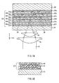
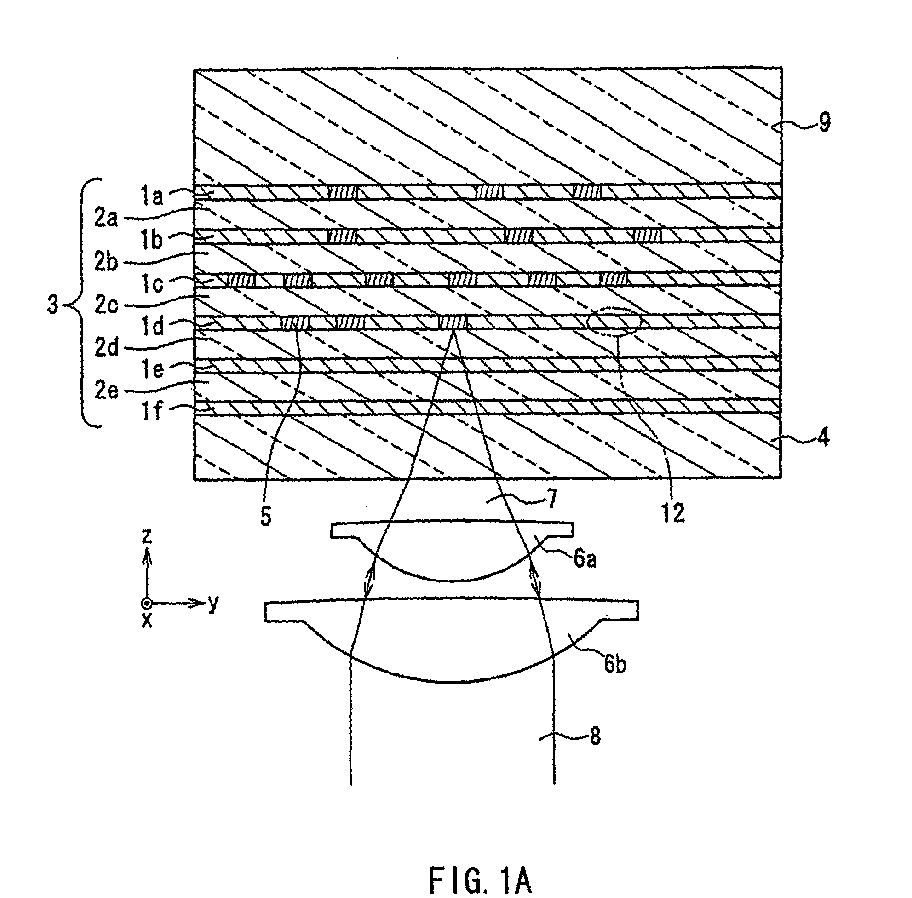
- Figures 1A and 1B show a cross-sectional configuration of the information recording medium and a state in which information is recorded and reproduced in the embodiment of the present invention.
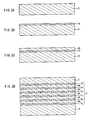
- Figures 2A to 2D are cross-sectional views showing each step of producing an information recording medium according to this embodiment.
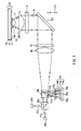
- Figure 3 shows a schematic configuration of an optical head of an optical information recording/reproducing apparatus according to this embodiment.
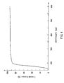
- Figure 4 shows a spectral transmittance curve of the recording layer of an example of the information recording medium according to this embodiment.
- a recording portion 3 and a protective layer 4 are formed on a substrate 9, a recording portion 3 and a protective layer 4 are formed.
- a plurality of recording layers are laminated via intermediate layers. That is to say, in the recording portion 3, from the side of the substrate 9, a recording layer 1a, an intermediate layer 2a, a recording layer 1b, ..., a recording layer 1e, an intermediate layer 2e, and a recording layer 1f are laminated sequentially.
- a plurality of recording layers in the recording portion 3 in addition to two-dimensional recording of information, three-dimensional recording capable of recording information by superimposing a plurality of layers in the thickness direction can be achieved.
- an arbitrary recording layer in the recording layers 1a to 1f will be referred to as a recording layer 1 and an arbitrary intermediate layer in the intermediate layers 2a to 2e will be referred to as an intermediate layer 2.
- the information recording medium of this embodiment at the time of recording and reproducing information, light is incident on the side of the protective layer 4.
- laser light 8 is allowed to be focused on any one of the recording layers 1a to 1f by the objective lenses (lens pair 6a and 6b) (converging light beam 7), and an information bit 5 is formed.
- laser light 8 is allowed to be focused on a desired layer of the recording layers 1a to 1f by the objective lenses (lens pair 6a and 6b) (converging light beam 7) so as to reproduce information by light reflected by the information bit 5.
- Figure 1B is an enlarged view showing the recording layer 1 (a region 12 shown in Figure 1A).
- the recording layer 1 is formed of a particle-holding material (binder) 10 in which particles 11 are dispersed.
- the particles 11 are made of a material that is substantially transparent to recording light and reproducing light, and absorbs at least a part of light with a predetermined wavelength.
- This predetermined wavelength is shorter than the wavelength of the recording light (recording wavelength) and the wavelength of the reproducing light (reproducing wavelength), and the absorption rate of the particles 11 with respect to the light with a predetermined wavelength is higher than the absorption rate of the particles 11 with respect to the recording light and reproducing light.
- this predetermined wavelength is included in the predetermined range of wavelengths including the wavelength of the absorption spectrum of the particles 11 (in the range of the wavelength in which the transmittance of the particles is reduced) and the absorption rate of the particles 11 with respect to the light of this predetermined wavelength is preferably 5% or more and more preferably 20% or more per recording layer. Furthermore, it is preferable that the average particle-size of the particles 11 is smaller than the recording wavelength and the reproducing wavelength. This is because optical loss due to the diffraction loss of the recording light and reproducing light by the particles 11 is suppressed.
- the particle-size of the particles 11 can be a quarter of the recording wavelength and the reproducing wavelength, since not only the diffraction loss but also the scattering loss can be suppressed, the optical loss of the recording light and the reproducing light can be reduced.
- the particle-holding material 10 is made of a material that is substantially transparent to the recording light and the reproducing light. Furthermore, since the particle-holding material 10 is used for recording materials, it is formed of, for example, a material whose optical constant changes at predetermined temperature, for example, a material whose refractive index changes (e.g., occurrence of thermal deformation, etc.) at a predetermined temperature.
- a material whose optical constant changes at predetermined temperature for example, a material whose refractive index changes (e.g., occurrence of thermal deformation, etc.) at a predetermined temperature.
- PMMA a photopolymer resin, an ultraviolet curable resin, polyester, or the like, can be used.
- the recording layer 1 includes 1 wt.% to 95 wt.% of the particles 11.
- the thickness of one recording layer is thin, e.g., about 1 ⁇ m
- the particle-holding material 10 functions as a recording material
- the difference between the refractive index of the particles 11 and the refractive index of the particle-holding material 10 is 0.5 or less, it is possible to suppress the scattering loss of incident light, thus improving the efficiency in using light.
- the intermediate layer 2 is substantially transparent to the recording light and the reproducing light.
- PMMA a photopolymer resin, an ultraviolet curable resin, polyester, or the like
- the intermediate layer 2 may be formed of the same material as that of the particle-holding material 10 of the recording layer 1.
- the substrate 9 can be formed of, for example, polycarbonate, PMMA, a norbornene resin (for example, "ARTON” (JSR Corporation)), a cycloolefin resin (for example, "ZEONEX” (ZEON CORPORATION, JAPAN)), or the like.
- the protective layer 4 can be formed of a transparent material, and for example, polycarbonate, PMMA, a norbornene resin (for example, "ARTON” (JSR Corporation)), a cycloolefin resin (for example, "ZEONEX” (ZEON CORPORATION, JAPAN)), or the like, can be used.
- the particles 11 and the particle-holding material 10 are substantially transparent to the recording light and the reproducing light. Therefore, in the information recording medium having a multilayered recording layer in this embodiment, the recording light and the reproducing light can reach the layer (a recording layer 1a in Figure 1) that is the most distant from the surface on which light is incident, without much attenuation, enabling information to be recorded and reproduced three-dimensionally
- a nonlinear absorption phenomenon such as the two-photon absorption, ormultiphoton absorption, is induced at a high rate in the focal point with high optical power density (photon density).
- photon density optical power density
- An example of the nonlinear absorption phenomenon includes: the case where if the absorption sensitivity has a threshold value (in particular, in this embodiment, the threshold value is relatively large (for example, the energy threshold value: 10 pJ/ ⁇ m 2 or more)), the two-photon absorption in which the absorption sensitivity is proportional to almost the square of the energy of light, or the multiple photon absorption in which the absorption sensitivity is proportional to almost the n-th power (n is an integer of 3 or more) of the energy of light occurs; the case where the two-photon absorption or the multiple photon absorption triggers plasma, and the combination thereof, and the like.
- the threshold value in particular, in this embodiment, the threshold value is relatively large (for example, the energy threshold value: 10 pJ/ ⁇ m 2 or more)
- the two-photon absorption in which the absorption sensitivity is proportional to almost the square of the energy of light or the multiple photon absorption in which the absorption sensitivity is proportional to almost the n-th power (n
- the recording layer 1 in the focal point absorbs two-photons at the same time, and it looks as if the recording layer were irradiated with the light with a half wavelength of the recording wavelength.
- the particles 11 are formed of materials that absorb at least a part of the light with a half wavelength of the recording wavelength of the particles 11 (the predetermined wavelength is set to be half of the recording wavelength)
- the particles 11 absorb the recording light at the focal point of the recording light.
- Heat caused by the light absorption of the particles 11 raises the temperature of the recording layer and reaches the predetermined temperature, and the optical constant of the particle-holding material 10 changes so as to form information bit 5.
- the optical constant of the particles 11 does not change for themselves but they act as a catalyst for changing the optical constant of the particle-holding material 10 so as to form the information bit 5.
- the pulse width of the recording light is in the range from 100 femtoseconds to 10 nanoseconds, and more preferably, in the range from 1 picosecond to 100 picoseconds.
- the threshold value of the peak power for recording one bit on the information recording medium tends to be reduced. This is thought because when the pulse width of the laser light is increased, the energy is increased by the increment thereof.
- the pulse width is set to be 1 picosecond or more.
- the energy threshold value necessary for recording of one bit is minimum with respect to the laser light with the pulse width of several picoseconds.
- the energy threshold value gradually tends to increase. Therefore, practically, in order to suppress the energy threshold value to about 5 nJ or less, recording with a pulse width of 100 picoseconds or less is desired.
- the energy threshold value is obtained as a value by multiplying the pulse width of the laser light by the peak power threshold value.
- Figure 4 shows a spectral transmittance curve of an information recording medium, in which the recording portion 3 formed by laminating ten layers of 0.13 ⁇ m-thick recording layers 1 containing about 55 wt.% of particles 11 made of zinc oxide and about 45 wt.% of particle-holding material 10 made of polyester via intermediate layers 2, is disposed between the substrate 9 and the protective layer 4.
- the energy gap of the zinc oxide is 3.2 eV and the absorption spectrum wavelength is 388 nm.
- this information recording medium has a transmittance of about 90% including Fresnel reflectance of the surface of protective layer 4 and the surface of the substrate 9 of about 10% at the wavelength of 400 nm or more. Therefore, the recording layer 1 hardly absorbs and is transparent.
- the transmittance is lowered rapidly at the wavelength of 400 nm or less, and the transmittance becomes 0%, i.e., opaque at the wavelength of 370 nm. Therefore, in this information recording medium, it is possible to determine the predetermined wavelength in the range of 400 nm or less in which the transmittance is lowered rapidly. It is preferable to determine the predetermined wavelength in which the absorption rate is about 5% or more per one layer of the recording layers, and it is more preferable to determine the predetermined wavelength around 370 nm in which the absorption rate is 100%.
- the light having twice the wavelength of the predetermined wavelength is used as recording light and thus, it looks as if the focal point were irradiated with the light with the predetermined wavelength.
- the recording wavelength is set at 740 nm.
- the reproduction wavelength is set to be more than 400 nm in which the reproduction wavelength is practically transparent in the recording layer. Since such recording light and reproducing light are hardly absorbed by particles, they are not attenuated even when passing through the recording layer. Note here that when recording by the multiphoton absorption such as n-photon absorption, etc. is assumed, the wavelength of the recording light is set n-times of the predetermined wavelength and the same is true in the other cases.
- inorganic materials or semiconductor materials can be used as the particles 11, inorganic materials or semiconductor materials.
- the use of inorganic materials for the particles 11 enables the recording layer to be stable.
- the use of the semiconductor materials for the particles 11 enables the transmittance of the recording layer in a certain range of wavelengths to be lowered rapidly as shown in Figure 4. This property is more suitable for recording using the non-linear absorption such as the two-photon absorption.
- the reproducing light having the wavelength of 150 nm to 500 nm is used.
- the reproducing wavelength can be set to be 500 nm or less.
- the reproduction performance can be improved, and higher density recording can be carried out.
- Examples of such semiconductor materials include zinc oxide (ZnO) having an energy gap of 3.2 eV (absorption spectrum wavelength of 388 nm); tin oxide (SnO 2 ) having an energy gap of 3.8 eV (absorption spectrum wavelength of 326 nm); zinc sulfide (ZnS) having an energy gap of 3.6 eV (absorption spectrum wavelength of 344 nm); titanium oxide (TiO 2 ) having an energy gap of 3.2 eV (absorption spectrum wavelength of 388 nm); tungsten oxide (WO 3 ) having an energy gap of 3.2 eV (absorption spectrum wavelength of 388 nm); strontium titanate (SrTiO 3 ) having an energy gap of 3.2 eV (absorption spectrum wavelength of 388 nm); silicon carbide (SiC) having an energy gap of 3.0 eV (absorption spectrum wavelength of 413 nm); indium oxide (In 2 O 3 ) having an energy gap of 2.8
- a substrate 9 is prepared (see Figure 2A).
- a recording layer 1a is formed by applying a coating containing the particles 11 and the particle-holding material 10 by, for example, spin coating, etc. (see Figure 2B).
- an intermediate layer 2a is formed thereon by applying a coating containing materials for the intermediate layer by, for example, spin coating, etc. (see Figure 2C).
- a recording layer 1b, an intermediate layer 2b, a recording layer 1c, ... a recording layer 1f are formed thereon repeatedly, in the same manner.
- a protective layer 4 is formed by a method for applying a coating containing a material of the protective layer 4 or a film formation method (see Figure 2D).
- the excessive portion i.e., a part at the side where light is incident of the recording portion
- the protective layer 4 may be formed on the recording layer 1f. That is to say, on the recording layer 1f, a layer that is the same as the intermediate layers 2a to 2e further is formed so as to form the protective layer 4, or by forming the recording layer 1f thick, and a part of the recording layer 1f may be functioned as a part of the protective layer 4.
- the protective layer 4 it is not necessary to form the protective layer 4 by a different process from the process for producing the recording portion 3 and the protective layer 4 can be formed of materials substantially the same as those of the recording portion.
- an optical head of the optical information recording/reproducing apparatus of this embodiment is provided with two kinds of light sources 20a and 20b.
- beam splitters 18a and 18b In an optical path from the light sources 20a and 20b to the information recording medium 22, beam splitters 18a and 18b, a collimator lens 16, a focus/track error signal detection element 15, a mirror 121, a spherical aberration correction element 13, and an objective lens 6 (lens pair 6a and 6b) are arranged.
- the light source 20a is a semiconductor laser light source having the wavelength of, for example, 405 nm and is used for reproducing information.
- the light source 20b is a semiconductor pulse laser light source having the wavelength of, for example, 740 nm and the pulse width of, for example, 100 femtoseconds to 10 nanoseconds and is used for recording information.
- a laser light 21b emitted from the light source 20b is bent toward the y direction by the beam splitter 18a; is made into substantially parallel light by the collimator lens 16; is transmitted through a diffraction focus/track-error signal detection element 15 (using 0-order diffraction light); and allows its optical path to bend toward the z direction by the mirror 121.
- the laser light 8 bent in the z direction passes through a spherical aberration correction element 13 and is focused on (as a convergent light 7) the recording portion 3 of the information recording medium 22 by the objective lens 6.
- the information bit 5 is formed as shown in Figure 1.
- the information bit 5 is formed by the use of the change in the optical constant of the recording layer 1.
- the information bit 5 is formed by the use of the change in the refractive index or the change in the transmittance of the particle-holding material 10 of the recording layer 1, etc.
- a laser light 21a emitted from the light source 20a is transmitted through the beam splitters 18a and 18b; is made into substantially parallel light by the collimator lens 16; is transmitted through a diffraction focus/track-error signal detection element 15 (using the 0-order diffraction light); and allows its optical path to bend toward the z direction by the mirror 121. Then, the laser light 8 bent in the z direction passes through the spherical aberration correction element 13 and is focused (as a convergent light 7) on the recording portion 3 of the information recording medium 22 by the objective lens 6.
- the light reflected by the information bit 5 formed on the recording layer 1 is bent in the opposite direction; passes sequentially through the objective lens 6, the spherical aberration correction element 13, and the mirror 121; is divided into a plurality of lights by the diffraction focus/track-error signal detection element 15 (first-order diffractive light is used.
- the divided light is not shown in the optical path from the diffraction focus/track-error signal detection element 15 to the beam splitter 18b) and is formed into the convergent light by the collimator lens 16; and further deflected in the -z direction by the beam splitter 18b.
- a plurality of divided light 17a to 17c deflected in the -z direction is transmitted through respective pin holes 14a to 14c of a pin hole array 14, and then signals are detected by optical detectors 19a to 19c.
- the recording light source and reproducing light source are provided separately.
- one light source is shared for the recording light source and the reproducing light source.
- the light source can be configured such that for example, the light source having, for example, the wavelength of 740 nm is used and in recording, the laser light having a large peak power is emitted via pulse oscillation, and in reproducing, laser light having the small peak power is emitted via successive oscillation.
- the number of light sources is one and the configuration of the apparatus can be simplified.
- a pin-hole array 14 composed of a plurality of pin-holes is placed substantially at the focal point of the entire divided light 17a to 17c.
- separate pin-holes may be placed corresponding to the respective focal points.
- the sizes of the pin-holes 14a to 14b are made to be smaller than the respective convergent light 17a to 17c, whereby light only in the central portion of the convergent light 17a to 17c can be detected and unnecessary high-order aberration light distributed around the periphery of the convergent light 17a to 17c can be removed.
- S/N of not only reproducing signals but also servo error signals can be improved.
- the signal intensity is increased by using APD (avalanche photodiode) for a photodetector 19.
- APD avalanche photodiode
- divided light 17a to 17c may be detected respectively by the photodetectors 19a to 19c whose areas are smaller than the respective divided light 17a to 17c. In this case, the same effect can be obtained.
- the divided light 17b and 17c corresponding to the track error signals are allowed to pass through the pin-holes 14b and 14c of the pin-hole array 14 and detected at the photodetector 19b and 19c, and the divided light 17a corresponding to the focus error signal is not allowed to pass through the pin-hole and detected directly by, for example, a four-dividing photodetector 19a.
- the focus detection method for example, an astigmatism method can be used.
- the area of the photodetector 19a can be made to be smaller than the cross-sectional area of the divided light 17a at the detection point, the high-order aberration component can be reduced.
- NA the numerical aperture
- the numerical aperture can be increased.
- the information bit 5 is recorded three-dimensionally on the recording portion 3 sequentially in the order in which the recording light does not pass through the information bit 5 that has already been recorded.
- the recording in such an order it is possible to reduce stray light such as scattered light and unnecessary diffracted light from the information bit 5.
- the recording in the above-mentioned order can be possible.
- information is recorded three dimensionally in the -z direction in the order from the recording layer 1a, the recording layer 1b, the recording layer 1c....
- the thickness of the recording layer 1 through which the convergent light 7 passes is different depends upon the recording depth of the information bit 5, it is preferable that recording is carried out while controlling the amount of spherical aberration in accordance with the recording depth by the spherical aberration correction element 13 provided in the optical path from the light sources 20a and 20b to the objective lens 6.
- the spherical aberration correction element 13 a liquid crystal element capable of changing the refractive index distribution, a beam expander, in which a concave lens and a convex lens are combined and the interval between both lenses in the direction of an optical axis can be changed by an actuator, and the like can be used.
- the recording order is not always limited to the -z direction as long as the convergent light 7 does not pass through the information bit 5 that has already been recorded if unrecorded portions of the information bit 5 are present.
- Figures 5A and 5B show a cross-sectional configuration of the information recording medium and a state in which information is recorded and reproduced in the embodiment of the present invention.
- a recording portion 33 and a protective layer 34 are formed on a substrate 39.
- a plurality of laminated bodies each composed of a recording layer and an auxiliary recording layer (a particle-containing layer) are laminated via intermediate layers. That is to say, in the recording portion 33, from the side of the substrate 39, an auxiliary recording layer 37a, a recording layer 31a, an intermediate layer 32a, an auxiliary recording layer 37b, a recording layer 31b, an intermediate layer 32b, ..., an intermediate layer 32e, an auxiliary recording layer 37f and a recording layer 31f are laminated sequentially.
- an arbitrary recording layer in the recording layers 31a to 31f will be referred to as a recording layer 31; an arbitrary intermediate layer in the intermediate layers 32a to 32e will be referred to as an intermediate layer 32; and an arbitrary auxiliary recording layer in the intermediate layers 37a to 37e will be referred to as an auxiliary recording layer 37.
- Figure 5B is an enlarged view showing the recording layer 31 and the auxiliary recording layer 37 (in the region 36 shown in Figure 5A).
- the auxiliary recording layer 37 is provided in contact with the recording layer 31 and the auxiliary recording layer 37 is formed of the particle-holding material 40 in which particles 41 are dispersed.
- the particles 41 have the same properties and functions and can be formed of the same material as the particles 11 contained in the recording layer 1 of the information recording medium explained in Embodiment 1.
- the particle-holding material 40 is required to be substantially transparent to the recording light and the reproducing light similar to the particle-holding material 10 contained in the recording layer included in the information recording medium in Embodiment 1.
- the optical constant of the particle-holding material 40 does not necessarily change at the predetermined temperature and it is rather preferable that the optical constant does not change. This is because in the information recording medium of this embodiment, the particle-holding material 40 does not function as a recording material but recording is carried out on the recording layer 31.
- the recording layer 31 a material whose refractive index or transmittance changes at the predetermined temperature is used, and a resin, tellurium glass, chalcogenide glass, and the like can be used. However, since a plurality of the recording layers are laminated to form a multi-layered structure, in order to reduce the loss of light, it is preferable that the recording layer is substantially transparent to the recording light and the reproducing light.
- the substrate 39, the protective layer 34 and the intermediate layer 32 have the same functions as those of the substrate 9, the protective layer 4 and the intermediate layer 2 respectively and can be formed of the same materials.
- the information recording medium of this embodiment like the recording layer 1 of the information recording medium of Embodiment 1, at the focal point of the recording light, a nonlinear absorption phenomenon such as the two-photon absorption is induced in the auxiliary recording layer 37 and the particles 41 absorb the recording light.
- the particles 41 absorb light and generate heat, and the heat is transferred to the recording layer 31 provided in contact with the auxiliary recording layer 37, thus increasing the temperature of the recording layer 31.
- the optical constant of the recording layer 31 changes and the information bit 35 is formed. According to this information recording medium, the recording sensitivity is improved versus that of the conventional information recording medium.
- the recording light has a peak power of several tens to several hundreds mW or more and several kW or less, and the pulse width of in the range from 100 femtoseconds to 10 nanoseconds (more preferably, in the range from 1 picosecond to 100 picoseconds).
- the optical information recording/reproducing apparatus shown in Figure 3 can be used.
- Figures 6A and 6B show a cross-sectional configuration of the information recording medium and a state in which information is recorded/reproduced in the embodiment of the present invention.
- the information recording medium of this embodiment on a substrate 49, a recording portion 43 and a protective layer 44 are formed.
- the information recording medium of this embodiment is different from the information recording media according to Embodiments 1 and 2 in that the whole recording portion 43 functions as a recording layer (particle-containing layer) 41.
- the whole recording portion 43 functions as a recording layer (particle-containing layer) 41.
- rows of the information bits 45 are recorded.
- FIG 6B is an enlarged view showing the recording layer 41 (in the region 46 shown in Figure 6A).
- the recording layer 41 is formed of the particle-holding material 50 in which particles 51 are dispersed.
- the particles 51 have the same properties and functions as those contained in the recording layer 1 of the information recording medium explained in Embodiment 1 and can be formed of the same materials as those in Embodiment 1.
- it is preferable that the content of the particles 51 is in the range from 0.3 wt.% to 10 wt.%.
- the particle-holding material 50 has the same properties and functions as those of the particles-holding material 10 contained in the recording layer 1 of the information recording medium shown in Embodiment 1 and can be formed of the same materials as in Embodiment 1. In the case where the substrate 49 and the protective layer 44 are formed of the same material, the structure is simplified further and can be produced at low cost.
- the recording light has a peak power of several tens to several hundreds mW or more and several kW or less, and the pulse width of in the range from 100 femtoseconds to 10 nanoseconds (more preferably, in the range from 1 picosecond to 100 picoseconds).
- the information recording medium in this embodiment can be produced by applying a coating containing the particles 51 and the particle-holding material 50 on the substrate 49, or by forming the recording layer 41 by injection molding. With such methods, the information recording medium can be formed easily at low cost.
- the embodiments of the present invention are explained.
- the present invention is not necessarily limited to these embodiments. It is possible to combine information recording media and the production methods therefof, and to combine the configurations of the optical information recording/reproducing apparatuses of the embodiments. Thus, the same effects can be obtained.
- the information recording medium and the optical information recording/reproducing apparatus of the present invention may include a rewritable type apparatus in addition to a write-one-type apparatus.
- the information recording medium including six layers of recording layers was explained.
- the number of laminating is not limited to six, and the number of the recording layers to be laminated layers is in the range of two or more and 100 layer or less.
- an optical disk was described as an example of the information recording medium, but the present invention is not limited to this alone, and the optical disk of the present invention may include a card type, drum type, and tape type media.
- the information recording medium of this Example is an example of the information recording medium as shown in Figure 1 explained in Embodiment 1.
- a plurality of recording layers each having a thickness of 0.13 ⁇ m to 1 ⁇ m and intermediate layers each having a thickness of 3 ⁇ m were laminated alternately by spin coating so as to form a recording portion 3 (recording layers 1a to 1f and intermediate layers 2a to 2e), and further polycarbonate protective layer 4 (thickness: 100 ⁇ m) was formed.
- the recording layers 1a to 1f were formed of particles 11 including 55 wt.% of zinc oxide (average particle-size of 0.03 ⁇ m) and a particle-holding material 10 containing 45 wt.% of an ultraviolet curable resin. Furthermore, the intermediate layers 2a to 2e were formed of an ultraviolet curable resin.
- the spectral transmittance curve of the information recording medium of this Example was substantially the same as that shown in Figure 4. Then, the predetermined wavelength was set to 370 nm and the recording wavelength was set to 740 nm.
- Figure 7 shows the measurement results of the energy threshold value and the peak power threshold value at the time of one bit recording with respect to the information recording medium when the pulse width was changed and irradiation with pulse light with the wavelength of 740 nm was carried out.
- the threshold value of the peak power for recording one bit on the information recording medium tends to be lowered.
- the pulse width By setting the pulse width to be one picosecond or more, the peak power threshold value could be suppressed to 3 kW or less.
- the energy threshold value required for one-bit recording was a minimum with respect to laser light with the pulse width of several picoseconds. With the increase in the pulse width, the energy threshold value tends to be increased gradually. By setting the pulse width to 100 picoseconds or less, the energy threshold value could be suppressed to 5 nJ or less.
- the recording sensitivity is improved, and therefore one information bit can be formed by one pulse even if laser light having extremely high peak power is not used as conventionally. Therefore, it is possible to provide an information recording medium capable of recording with high sensitivity and at high speed, and an optical information recording/reproducing apparatus.
Landscapes
- Engineering & Computer Science (AREA)
- Chemical & Material Sciences (AREA)
- Nanotechnology (AREA)
- Physics & Mathematics (AREA)
- Inorganic Chemistry (AREA)
- Mathematical Physics (AREA)
- Crystallography & Structural Chemistry (AREA)
- Composite Materials (AREA)
- Theoretical Computer Science (AREA)
- Condensed Matter Physics & Semiconductors (AREA)
- General Physics & Mathematics (AREA)
- Materials Engineering (AREA)
- Dispersion Chemistry (AREA)
- Manufacturing & Machinery (AREA)
- Optical Record Carriers And Manufacture Thereof (AREA)
- Optical Recording Or Reproduction (AREA)
Abstract
An information recording medium has a recording portion where
three-dimensional information can be recorded. The recording
portion includes at least one particle-containing layer
(recording layer or a recording auxiliary layer) containing
particles absorbing at least a part of light having a
predetermined wavelength and substantially transparent to a
recording light and a reproducing light having a wavelength
longer than the predetermined wavelength and a particle
holding material substantially transparent to the recording
and reproducing lights. The mean particle size of the
particles is preferably shorter than the wavelengths of the
recording and reproducing lights.
Description
The present invention relates to an information recording medium
capable of three-dimensionally recording information and a method for
producing the same, and an optical information recording/reproducing
apparatus, and more particularly to an information recording medium
capable of recording with high sensitivity and at high speed and a method for
producing the same, and an optical information recording/reproducing
apparatus.
One of the conventional information recording medium capable of
three-dimensionally recording information is shown in Figure 8 (Yoshimasa
Kawata et al.: Three-dimensional optical memory using an organic
multilayered recording medium; Optics Japan 2000, Proceedings, p.95-96,
7pB12 (2000)). In this information recording medium, on a glass substrate
104, recording layers 101a to 101d made of urethane-urea copolymer material
that is a photon-mode recording material, and intermediate layers 102a to
102c made of a PVA (polyvinyl alcohol) film and a PMMA (polymethyl
methacrylate) film are laminated alternately.
However, there has been a problem in the above-mentioned
conventional information recording medium that the recording sensitivity of
the recording layer was not good. Accordingly, in the case of a recording
method in which one information bit is formed by one pulse, it is necessary to
use a femtosecond laser having an extremely large peak power (about 100
kW) as a light source, and thus the structure of the light source becomes
complicated. Furthermore, there has been another problem in that in the
case where a light source with a smaller peak power is used, pulse irradiation
at the same place is required to be repeated several times (for example, from
several tens to several thousands times) (i.e., since a photon-mode recording
material is used for a recording layer, accumulated recording of refractive
index change is possible), whereby the speed of writing information is
reduced.
The information recording medium of the present invention a
recording portion capable of recording information three-dimensionally. The
recording portion comprises at least one particle-containing layer comprising:
particles that absorb at least a part of light with a predetermined
wavelength; are substantially transparent to recording light and reproducing
light with wavelengths longer than the predetermined wavelength; and have
an absorption rate with respect to the light with the predetermined
wavelength that is higher than the absorption rate with respect to the
recording light and the reproducing light, and a particle-holding material
that is substantially transparent to the recording light and the reproducing
light.
The method for producing an information recording medium of the
present invention includes forming a coating containing particles and a
particle-holding material; and applying the coating so as to form a
particle-containing layer.
The optical information recording/reproducing apparatus of the
present invention includes a light source for emitting recording light; a light
source for emitting reproducing light; an objective lens for focusing the light
emitted from the light source on the information recording medium; and a
photodetector for detecting light reflected by the information recording
medium. By using the change in the optical constant of the recording
portion of the information recording medium, an information bit is recorded
on the recording portion three-dimensionally.
According to the information recording medium of the present
invention, since the recording sensitivity is enhanced, it is possible to form
one information bit by one pulse even if laser light having an extremely high
peak power, which was required in the conventional example, is not used.
Thus, the present invention can provide an information recording medium
capable of recording information with high sensitivity at high speed. Note
here that, throughout the description, the term "substantially transparent to
recording light and reproducing light" means that almost all light
components of the recording light and the reproducing light, except for
scattered light components, are allowed to be transmitted without being
absorbed. Specifically, for example, it is preferable that the transmittance
with respect to one particle-containing layer is 95% or more, and more
preferably 99% or more.
In the information recording medium of the present invention, it is
preferable that the average particle-size of the particles is shorter than the
wavelength of the recording light and the wavelength of the reproducing
light. It is more preferable that the average particle-size of the particles is
shorter than a quarter of the wavelength of the recording light and a quarter
of the wavelength of the reproducing light. This is advantageous because,
for example, in the case where a plurality of particle-containing layers are
included in the recording portion, diffraction loss or scattering loss is
suppressed so as to prevent the optical loss. Note here that in this case,
since a part of particles is aggregated, particles (aggregate) whose apparent
particle-size is larger than the wavelength of the recording light and the
reproducing light may be present. Furthermore, even when the particles are
aggregated, it is preferable that the apparent particle-size of the particles in
an aggregated state is shorter than the wavelength of the recording light and
the reproducing light.
In the information recording medium of the present invention, the
particle-containing layer may be a recording layer, and the particle-holding
material may have an optical constant that changes at a predetermined
temperature. In this case, the recording portion includes a plurality of the
recording layers and the plurality of the recording layers may be laminated
via intermediate layers that are substantially transparent to the recording
light and the reproducing light so as to form a multilayered structure.
Furthermore, in the information recording medium of the present
invention, the recording portion further may include a recording layer and
the particle-containing layer may be an auxiliary recording layer disposed in
contact with the recording layer. In this case, a multilayered structure may
be obtained by providing a plurality of laminate bodies composed of the
recording layer and the auxiliary recording layer, and by providing an
intermediate layers that are substantially transparent to the recording light
and the reproducing light between the laminated bodies that are adjacent to
each other.
Furthermore, in the information recording medium of the present
invention, the particle-containing layer may be a recording layer, and the
particle-holding material may have an optical constant that changes at a
predetermined temperature, and an entire recording portion may be formed
as one recording layer.
In the information recording medium of the present invention, a
protective layer that is substantially transparent to the recording light and
the reproducing light is provided at the side of the recording portion on which
light is incident. It is advantageous because the recording portion can be
protected from damage or dust, etc.
Furthermore, it is preferable that the protective layer or the
intermediate layer is made of the same material as that of the
particle-holding material. It is advantageous because an excellent interface
between the particle-containing layer and the protective layer or the
intermediate layer can be formed and also the material maintenance can be
facilitated. Herein, the term "the same material" means the same kind of
material. Thus, for example, resins each having different molecular weights
due to the difference in the polymerization degree are regarded as the same
material.
In the information recording medium of the present invention, it is
preferable that the difference between the refractive index of the
particle-holding material and the refractive index of the particles is 0.5 or
less. This is advantageous because the scattering loss can be suppressed.
In the information recording medium of the present invention, it is
preferable that the particles include an inorganic material or a semiconductor
material. When the particles are formed of inorganic materials, the
particle-containing layer can be stabilized. When the particles are formed of
semiconductor materials, since the transmittance can be reduced rapidly in a
certain range of wavelengths, the material is suitable for recording
information by using a nonlinear absorption phenomenon. In such
semiconductor materials, it is preferable that an energy gap is 2.5 eV or more
and 8.3 eV or less. For example, it is preferable that the material include at
least one selected from the group consisting of zinc oxide, tin oxide, zinc
sulfide, titanium oxide, tungsten oxide, strontium titanate, silicon carbide,
indium oxide and cadmium sulfide. This is advantageous because since the
wavelength of the reproducing light can be set to be 500 nm or less, so that
the reproducing resolution and recording density can be improved.
In the information recording medium using a plurality of
particle-containing layers as a recording layer or an auxiliary recording layer,
it is preferable that the particle-containing layer contains 1 wt.% or more and
95 wt.% or less of the particles. In this case, it is advantageous because by
setting the content of the particles to be 1 wt.% or more, the recording
sensitivity can be improved to the practical level, and by setting the content
of particles to be 95 wt.% or less, the optical loss such as scattering of light,
can be reduced to a practical level.
In the information recording medium in which the particle-containing
layer is a recording layer and the whole recording portion is one recording
layer, it is preferable that the particle-containing layer contains 0.3 wt.% or
more and 10 wt.% or less of the particles. In this case, it is advantageous
because by setting the content of particles to be 0.3 wt.% or more, the
recording sensitivity can be improved to the practical level, and by setting the
content of the particles to be 10 wt.% or less, the optical loss such as
scattering of light can be reduced to a practical level.
Furthermore, in the information recording medium of the present
invention, it is preferable that the particle-holding material is formed of a
resin. It is advantageous because the particle-containing layer can be
formed easily.
According to a method for producing the information recording
medium of the present invention, the information recording medium of the
present invention can be produced easily and at low cost.
In the method for producing the information recording medium of the
present invention, it is preferable that the method further includes forming
an intermediate layer by applying the coating containing materials
substantially transparent to recording light and reproducing light, wherein in
the step of forming the particle-containing layer, a material having an optical
constant that changes at a predetermined temperature is used as the
particle-holding material, and the step of forming the particle-containing
layer and the step of forming the intermediate layer are repeated alternately
a predetermined number of times. Thus, the particle-containing layer can
be a recording layer, and a laminated bodies, in which a plurality of the
recording layers are laminated, can be produced easily and at low cost.
In the method for producing the information recording medium of the
present invention, the method further may include forming an intermediate
layer by applying a coating containing a material that is substantially
transparent to the recording light and the reproducing light; and forming a
recording layer by applying the coating containing a material having an
optical constant that changes at a predetermined temperature; wherein the
step of forming the particle-containing layer, the step of forming the recording
layer, and the step of forming the intermediate layer are repeated in a
predetermined order and predetermined number of times periodically.
According to this method, the information recording medium including a
plurality of the recording layers and the auxiliary recording layers composed
of the particle-containing layer can be produced easily and at low cost.
According to the optical information recording/reproducing apparatus
of the present invention, information can be recorded on the information
recording/reproducing medium of the present invention with high density and
at high speed.
In the optical information recording/reproducing apparatus, it is
preferable that the light source for emitting recording light is a pulse laser
light source and a pulse width is in the range from 100 femtoseconds to 10
nanoseconds. It is more preferable that the pulse width is in the range from
1 picosecond to 100 picoseconds. This is advantageous because the recording
sensitivity can further be enhanced.
In the optical information recording/reproducing apparatus of the
present invention, it is preferable that the wavelength of the light source for
emitting reproducing light is shorter than the wavelength of the light source
for emitting recording light. This is advantageous because reproducing
resolution and the recording density can be improved.
In the optical information recording/reproducing apparatus of the
present invention, it is preferable that the information bit is recorded on the
recording portion of the information recording medium by using a nonlinear
absorption phenomenon. It is preferable that the nonlinear absorption
phenomenon includes the two-photon absorption or the multiphoton
absorption.
In the optical information recording/reproducing apparatus of the
present invention, it is preferable that the information bit is recorded
three-dimensionally on the recording portion of the information recording
medium in the order in which the recording light does not pass through the
information bit that has already been recorded on the recording portion. For
example, it is preferable that the information bit is recorded sequentially in
the order from the position distant from the objective lens to the position near
the objective lens in the recording portion of the information recording
medium. This is advantageous because by recording information bits in
such an order, it is possible to reduce stray light such as scattered light, an
unnecessary refractive light, and the like.
In the optical information recording/reproducing apparatus of the
present invention, it is preferable that one light source is shared for the light
source for emitting the recording light and the light source for emitting the
reproducing light. This is advantageous because the number of light sources
is one, and thus the configuration can be simplified.
Hereinafter, the embodiments of the present invention will be
explained with reference to drawings.
An information recording medium and a method for producing the
same, and an optical information recording/reproducing apparatus according
to Embodiment 1 of the present invention will be explained with reference to
drawings. Figures 1A and 1B show a cross-sectional configuration of the
information recording medium and a state in which information is recorded
and reproduced in the embodiment of the present invention. Figures 2A to
2D are cross-sectional views showing each step of producing an information
recording medium according to this embodiment. Figure 3 shows a
schematic configuration of an optical head of an optical information
recording/reproducing apparatus according to this embodiment. Figure 4
shows a spectral transmittance curve of the recording layer of an example of
the information recording medium according to this embodiment.
As shown in Figure 1A, in the information recording medium of this
embodiment, on a substrate 9, a recording portion 3 and a protective layer 4
are formed. In the recording portion 3, a plurality of recording layers
(particle-containing layers) are laminated via intermediate layers. That is to
say, in the recording portion 3, from the side of the substrate 9, a recording
layer 1a, an intermediate layer 2a, a recording layer 1b, ..., a recording layer
1e, an intermediate layer 2e, and a recording layer 1f are laminated
sequentially. In the information recording medium of this embodiment, by
including a plurality of recording layers in the recording portion 3, in addition
to two-dimensional recording of information, three-dimensional recording
capable of recording information by superimposing a plurality of layers in the
thickness direction can be achieved. Note here that hereinafter, an arbitrary
recording layer in the recording layers 1a to 1f will be referred to as a
recording layer 1 and an arbitrary intermediate layer in the intermediate
layers 2a to 2e will be referred to as an intermediate layer 2.
As shown in Figure 1A, in the information recording medium of this
embodiment, at the time of recording and reproducing information, light is
incident on the side of the protective layer 4. At the time of recording
information, laser light 8 is allowed to be focused on any one of the recording
layers 1a to 1f by the objective lenses ( lens pair 6a and 6b) (converging light
beam 7), and an information bit 5 is formed. At the time of reproducing
information, laser light 8 is allowed to be focused on a desired layer of the
recording layers 1a to 1f by the objective lenses ( lens pair 6a and 6b)
(converging light beam 7) so as to reproduce information by light reflected by
the information bit 5.
Figure 1B is an enlarged view showing the recording layer 1 (a region
12 shown in Figure 1A). As shown in Figure 1B, the recording layer 1 is
formed of a particle-holding material (binder) 10 in which particles 11 are
dispersed.
The particles 11 are made of a material that is substantially
transparent to recording light and reproducing light, and absorbs at least a
part of light with a predetermined wavelength. This predetermined
wavelength is shorter than the wavelength of the recording light (recording
wavelength) and the wavelength of the reproducing light (reproducing
wavelength), and the absorption rate of the particles 11 with respect to the
light with a predetermined wavelength is higher than the absorption rate of
the particles 11 with respect to the recording light and reproducing light.
Furthermore, this predetermined wavelength is included in the
predetermined range of wavelengths including the wavelength of the
absorption spectrum of the particles 11 (in the range of the wavelength in
which the transmittance of the particles is reduced) and the absorption rate
of the particles 11 with respect to the light of this predetermined wavelength
is preferably 5% or more and more preferably 20% or more per recording
layer. Furthermore, it is preferable that the average particle-size of the
particles 11 is smaller than the recording wavelength and the reproducing
wavelength. This is because optical loss due to the diffraction loss of the
recording light and reproducing light by the particles 11 is suppressed.
Furthermore, by making the particle-size of the particles 11 to be a quarter of
the recording wavelength and the reproducing wavelength, since not only the
diffraction loss but also the scattering loss can be suppressed, the optical loss
of the recording light and the reproducing light can be reduced.
The particle-holding material 10 is made of a material that is
substantially transparent to the recording light and the reproducing light.
Furthermore, since the particle-holding material 10 is used for recording
materials, it is formed of, for example, a material whose optical constant
changes at predetermined temperature, for example, a material whose
refractive index changes (e.g., occurrence of thermal deformation, etc.) at a
predetermined temperature. For the particle-holding material 10, for
example, PMMA, a photopolymer resin, an ultraviolet curable resin,
polyester, or the like, can be used.
It is preferable that the recording layer 1 includes 1 wt.% to 95 wt.%
of the particles 11. When the thickness of one recording layer is thin, e.g.,
about 1 µm, if about 1 wt.% of the particles 11 are present, the recording
sensitivity can be improved and if about 95 wt.% of the particles 11 are
present, the optical loss due to light scattering can be suppressed.
Furthermore, as mentioned below, since the particle-holding material 10
functions as a recording material, it is preferable that 30 wt.% or more of the
particle-holding materials 10 are present. Therefore, it is preferable that the
particles 11 are contained in the range of 70 wt.% or less. Furthermore, in
order to achieve a sufficient recording sensitivity, the particles 11 are
contained in the range of 30 wt.% or more.
By setting the difference between the refractive index of the particles
11 and the refractive index of the particle-holding material 10 to be 0.5 or
less, it is possible to suppress the scattering loss of incident light, thus
improving the efficiency in using light.
The intermediate layer 2 is substantially transparent to the recording
light and the reproducing light. For example, PMMA, a photopolymer resin,
an ultraviolet curable resin, polyester, or the like, can be used. The
intermediate layer 2 may be formed of the same material as that of the
particle-holding material 10 of the recording layer 1.
The substrate 9 can be formed of, for example, polycarbonate, PMMA,
a norbornene resin (for example, "ARTON" (JSR Corporation)), a cycloolefin
resin (for example, "ZEONEX" (ZEON CORPORATION, JAPAN)), or the like.
The protective layer 4 can be formed of a transparent material, and for
example, polycarbonate, PMMA, a norbornene resin (for example, "ARTON"
(JSR Corporation)), a cycloolefin resin (for example, "ZEONEX" (ZEON
CORPORATION, JAPAN)), or the like, can be used.
Next, recording of information on the information recording medium
according to this embodiment will be explained.
The particles 11 and the particle-holding material 10 are
substantially transparent to the recording light and the reproducing light.
Therefore, in the information recording medium having a multilayered
recording layer in this embodiment, the recording light and the reproducing
light can reach the layer (a recording layer 1a in Figure 1) that is the most
distant from the surface on which light is incident, without much
attenuation, enabling information to be recorded and reproduced
three-dimensionally
When light with a relatively high peak power is focused on the
recording layer 1 as the recording light, a nonlinear absorption phenomenon
such as the two-photon absorption, ormultiphoton absorption, is induced at a
high rate in the focal point with high optical power density (photon density).
Note here that the nonlinear absorption phenomenon herein denotes a
phenomenon in which the absorption sensitivity of the recording layer 1 is not
proportional to the energy of light. An example of the nonlinear absorption
phenomenon includes: the case where if the absorption sensitivity has a
threshold value (in particular, in this embodiment, the threshold value is
relatively large (for example, the energy threshold value: 10 pJ/µm2 or more)),
the two-photon absorption in which the absorption sensitivity is proportional
to almost the square of the energy of light, or the multiple photon absorption
in which the absorption sensitivity is proportional to almost the n-th power (n
is an integer of 3 or more) of the energy of light occurs; the case where the
two-photon absorption or the multiple photon absorption triggers plasma, and
the combination thereof, and the like. For example, in the case where the
two-photon absorption occurs in the recording layer 1 in the focal point of the
recording light, the recording layer 1 in the focal point absorbs two-photons at
the same time, and it looks as if the recording layer were irradiated with the
light with a half wavelength of the recording wavelength. In this case, if the
particles 11 are formed of materials that absorb at least a part of the light
with a half wavelength of the recording wavelength of the particles 11 (the
predetermined wavelength is set to be half of the recording wavelength), the
particles 11 absorb the recording light at the focal point of the recording light.
Heat caused by the light absorption of the particles 11 raises the
temperature of the recording layer and reaches the predetermined
temperature, and the optical constant of the particle-holding material 10
changes so as to form information bit 5. Thus, it is thought that at the time
of recording, the optical constant of the particles 11 does not change for
themselves but they act as a catalyst for changing the optical constant of the
particle-holding material 10 so as to form the information bit 5.
In order to induce the nonlinear absorption phenomenon in the focal
point of the recording light, conventionally, it was necessary to use a laser
light with an extremely high peak power or to repeat irradiation at one place
multiple times in the case where the peak power is not so high. However,
according to the information recording medium of this embodiment, even if
the peak power is about several tens to several hundreds mW, such a
nonlinear absorption phenomenon can be induced. Furthermore, even if the
pulse laser light does not have such a high peak power, one information bit 5
can be formed by one pulse. This is thought because light is absorbed by the
particles 11, thereby the effect unique to the particles, that is, excellent
quantum effect or thermal transforming efficiency, etc. occurs and as a result,
various nonlinear absorption phenomena, for example, generation of plasma,
further are induced. Thereby, high speed recording using pulse laser light
with a relatively small peak power can be achieved.
It is preferable that the pulse width of the recording light is in the
range from 100 femtoseconds to 10 nanoseconds, and more preferably, in the
range from 1 picosecond to 100 picoseconds. In general, with the increase in
the pulse width of the laser light, the threshold value of the peak power for
recording one bit on the information recording medium tends to be reduced.
This is thought because when the pulse width of the laser light is increased,
the energy is increased by the increment thereof. By permitting the
recording at a relatively low peak power, the structure of the semiconductor
laser that is a light source can be simplified. This is because the
semiconductor laser with not so high peak power is not likely to be broken in
the end face in which light is emitted. Therefore, actually, in order to
suppress the peak power threshold value to be about 3 kW or less, it is
desirable that the pulse width is set to be 1 picosecond or more. On the
other hand, in general, the energy threshold value necessary for recording of
one bit is minimum with respect to the laser light with the pulse width of
several picoseconds. When the pulse width is increased, the energy
threshold value gradually tends to increase. Therefore, practically, in order
to suppress the energy threshold value to about 5 nJ or less, recording with a
pulse width of 100 picoseconds or less is desired. Note here that the energy
threshold value is obtained as a value by multiplying the pulse width of the
laser light by the peak power threshold value.
Hereinafter, the case where the particles 11 are formed of zinc oxide
will be explained as an example.
Figure 4 shows a spectral transmittance curve of an information
recording medium, in which the recording portion 3 formed by laminating ten
layers of 0.13 µm-thick recording layers 1 containing about 55 wt.% of
particles 11 made of zinc oxide and about 45 wt.% of particle-holding material
10 made of polyester via intermediate layers 2, is disposed between the
substrate 9 and the protective layer 4. Note here that the energy gap of the
zinc oxide is 3.2 eV and the absorption spectrum wavelength is 388 nm. As
shown in Figure 4, this information recording medium has a transmittance of
about 90% including Fresnel reflectance of the surface of protective layer 4
and the surface of the substrate 9 of about 10% at the wavelength of 400 nm
or more. Therefore, the recording layer 1 hardly absorbs and is transparent.
Furthermore, in this information recording medium, the transmittance is
lowered rapidly at the wavelength of 400 nm or less, and the transmittance
becomes 0%, i.e., opaque at the wavelength of 370 nm. Therefore, in this
information recording medium, it is possible to determine the predetermined
wavelength in the range of 400 nm or less in which the transmittance is
lowered rapidly. It is preferable to determine the predetermined wavelength
in which the absorption rate is about 5% or more per one layer of the
recording layers, and it is more preferable to determine the predetermined
wavelength around 370 nm in which the absorption rate is 100%. In this
recording layer 1, in the case where the recording of information by
two-photon absorption is assumed, the light having twice the wavelength of
the predetermined wavelength is used as recording light and thus, it looks as
if the focal point were irradiated with the light with the predetermined
wavelength. For example, when the predetermined wavelength is
determined at 370 nm, the recording wavelength is set at 740 nm.
Furthermore, the reproduction wavelength is set to be more than 400 nm in
which the reproduction wavelength is practically transparent in the recording
layer. Since such recording light and reproducing light are hardly absorbed
by particles, they are not attenuated even when passing through the
recording layer. Note here that when recording by the multiphoton
absorption such as n-photon absorption, etc. is assumed, the wavelength of
the recording light is set n-times of the predetermined wavelength and the
same is true in the other cases.
As the particles 11, inorganic materials or semiconductor materials
can be used. The use of inorganic materials for the particles 11 enables the
recording layer to be stable. Furthermore, the use of the semiconductor
materials for the particles 11 enables the transmittance of the recording layer
in a certain range of wavelengths to be lowered rapidly as shown in Figure 4.
This property is more suitable for recording using the non-linear absorption
such as the two-photon absorption. Furthermore, in order to obtain high
reproduction resolution, it is preferable that the reproducing light having the
wavelength of 150 nm to 500 nm is used. By using semiconductor materials
having an energy gap of 2.5 eV or more and 8.3 eV or less for the particles 11,
since the predetermined wavelength can be set to be smaller than 500 nm,
the reproducing wavelength can be set to be 500 nm or less. Thus, the
reproduction performance can be improved, and higher density recording can
be carried out. Examples of such semiconductor materials include zinc oxide
(ZnO) having an energy gap of 3.2 eV (absorption spectrum wavelength of 388
nm); tin oxide (SnO2) having an energy gap of 3.8 eV (absorption spectrum
wavelength of 326 nm); zinc sulfide (ZnS) having an energy gap of 3.6 eV
(absorption spectrum wavelength of 344 nm); titanium oxide (TiO2) having an
energy gap of 3.2 eV (absorption spectrum wavelength of 388 nm); tungsten
oxide (WO3) having an energy gap of 3.2 eV (absorption spectrum wavelength
of 388 nm); strontium titanate (SrTiO3) having an energy gap of 3.2 eV
(absorption spectrum wavelength of 388 nm); silicon carbide (SiC) having an
energy gap of 3.0 eV (absorption spectrum wavelength of 413 nm); indium
oxide (In2O3) having an energy gap of 2.8 eV (absorption spectrum
wavelength of 443 nm); cadmium sulfide (CdS) having an energy gap of 2.5
eV (absorption spectrum wavelength of 497 nm); and the like.
Next, a method for producing an information recording medium of
this embodiment will be explained with reference to Figures 2A to 2D.
Firstly, a substrate 9 is prepared (see Figure 2A). On the substrate
9, a recording layer 1a is formed by applying a coating containing the
particles 11 and the particle-holding material 10 by, for example, spin coating,
etc. (see Figure 2B). Furthermore, an intermediate layer 2a is formed
thereon by applying a coating containing materials for the intermediate layer
by, for example, spin coating, etc. (see Figure 2C). Furthermore, a recording
layer 1b, an intermediate layer 2b, a recording layer 1c, ... a recording layer
1f are formed thereon repeatedly, in the same manner. Finally, a protective
layer 4 is formed by a method for applying a coating containing a material of
the protective layer 4 or a film formation method (see Figure 2D). Thus, by
forming the recording layer 1 and the intermediate layer 2 by applying the
materials, an information recording medium of this embodiment can be
produced easily and at low cost.
Furthermore, by forming an excessive amount of the intermediate
layer or the recording layer, the excessive portion (i.e., a part at the side
where light is incident of the recording portion) may be formed as the
protective layer 4. That is to say, on the recording layer 1f, a layer that is
the same as the intermediate layers 2a to 2e further is formed so as to form
the protective layer 4, or by forming the recording layer 1f thick, and a part of
the recording layer 1f may be functioned as a part of the protective layer 4.
Thus, it is not necessary to form the protective layer 4 by a different process
from the process for producing the recording portion 3 and the protective
layer 4 can be formed of materials substantially the same as those of the
recording portion.
Next, an optical information recording/reproducing apparatus of this
embodiment will be explained. As shown in Figure 3, an optical head of the
optical information recording/reproducing apparatus of this embodiment is
provided with two kinds of light sources 20a and 20b. In an optical path
from the light sources 20a and 20b to the information recording medium 22,
beam splitters 18a and 18b, a collimator lens 16, a focus/track error signal
detection element 15, a mirror 121, a spherical aberration correction element
13, and an objective lens 6 ( lens pair 6a and 6b) are arranged. The light
source 20a is a semiconductor laser light source having the wavelength of, for
example, 405 nm and is used for reproducing information. The light source
20b is a semiconductor pulse laser light source having the wavelength of, for
example, 740 nm and the pulse width of, for example, 100 femtoseconds to 10
nanoseconds and is used for recording information.
At the time of recording, a laser light 21b emitted from the light
source 20b is bent toward the y direction by the beam splitter 18a; is made
into substantially parallel light by the collimator lens 16; is transmitted
through a diffraction focus/track-error signal detection element 15 (using
0-order diffraction light); and allows its optical path to bend toward the z
direction by the mirror 121. Then, the laser light 8 bent in the z direction,
passes through a spherical aberration correction element 13 and is focused on
(as a convergent light 7) the recording portion 3 of the information recording
medium 22 by the objective lens 6. Thus the information bit 5 is formed as
shown in Figure 1. The information bit 5 is formed by the use of the change
in the optical constant of the recording layer 1. In this embodiment, the
information bit 5 is formed by the use of the change in the refractive index or
the change in the transmittance of the particle-holding material 10 of the
recording layer 1, etc.
At the time of reproducing, a laser light 21a emitted from the light
source 20a is transmitted through the beam splitters 18a and 18b; is made
into substantially parallel light by the collimator lens 16; is transmitted
through a diffraction focus/track-error signal detection element 15 (using the
0-order diffraction light); and allows its optical path to bend toward the z
direction by the mirror 121. Then, the laser light 8 bent in the z direction
passes through the spherical aberration correction element 13 and is focused
(as a convergent light 7) on the recording portion 3 of the information
recording medium 22 by the objective lens 6. The light reflected by the
information bit 5 formed on the recording layer 1 is bent in the opposite
direction; passes sequentially through the objective lens 6, the spherical
aberration correction element 13, and the mirror 121; is divided into a
plurality of lights by the diffraction focus/track-error signal detection element
15 (first-order diffractive light is used. In Figure 3, for simplification, the
divided light is not shown in the optical path from the diffraction
focus/track-error signal detection element 15 to the beam splitter 18b) and is
formed into the convergent light by the collimator lens 16; and further
deflected in the -z direction by the beam splitter 18b. A plurality of divided
light 17a to 17c deflected in the -z direction is transmitted through respective
pin holes 14a to 14c of a pin hole array 14, and then signals are detected by
optical detectors 19a to 19c.
Note here that in the optical information recording/reproducing
apparatus of this embodiment, the recording light source and reproducing
light source are provided separately. However, one light source is shared for
the recording light source and the reproducing light source. In this case, the
light source can be configured such that for example, the light source having,
for example, the wavelength of 740 nm is used and in recording, the laser
light having a large peak power is emitted via pulse oscillation, and in
reproducing, laser light having the small peak power is emitted via successive
oscillation. Thus, the number of light sources is one and the configuration of
the apparatus can be simplified.
Furthermore, in this embodiment, a pin-hole array 14 composed of a
plurality of pin-holes is placed substantially at the focal point of the entire
divided light 17a to 17c. However, separate pin-holes may be placed
corresponding to the respective focal points. The sizes of the pin-holes 14a to
14b are made to be smaller than the respective convergent light 17a to 17c,
whereby light only in the central portion of the convergent light 17a to 17c
can be detected and unnecessary high-order aberration light distributed
around the periphery of the convergent light 17a to 17c can be removed.
Thus, S/N of not only reproducing signals but also servo error signals can be
improved. Note here that when the light amount is reduced by removing the
peripheral light of the divided light 17a to 17c, it is preferable that the signal
intensity is increased by using APD (avalanche photodiode) for a
photodetector 19. Note here that in the case of the information recording
medium in which a plurality of recording layers are provided, a large amount
of detected light cannot be obtained because of the limitation of the material.
Also for this reason, it is preferable to use APD.
Furthermore, instead of the pin-hole array 14, divided light 17a to 17c
may be detected respectively by the photodetectors 19a to 19c whose areas
are smaller than the respective divided light 17a to 17c. In this case, the
same effect can be obtained.
Furthermore, only the divided light 17b and 17c corresponding to the
track error signals are allowed to pass through the pin-holes 14b and 14c of
the pin-hole array 14 and detected at the photodetector 19b and 19c, and the
divided light 17a corresponding to the focus error signal is not allowed to pass
through the pin-hole and detected directly by, for example, a four-dividing
photodetector 19a. With such an arrangement, as the focus detection
method, for example, an astigmatism method can be used. Furthermore,
when the area of the photodetector 19a can be made to be smaller than the
cross-sectional area of the divided light 17a at the detection point, the
high-order aberration component can be reduced.
In this embodiment, by configuring the objective lens 6 as a lens pair,
the numerical aperture (NA) is increased (for example, NA is 0.85). Note
here that also in the case where the objective lens 6 is a single lens, the
numerical aperture can be increased.
In this embodiment, the information bit 5 is recorded
three-dimensionally on the recording portion 3 sequentially in the order in
which the recording light does not pass through the information bit 5 that has
already been recorded. By recording in such an order, it is possible to reduce
stray light such as scattered light and unnecessary diffracted light from the
information bit 5. Specifically, by forming the information bit 5 in the order
from the recording layer located at the most distant from the objective lens 6
(recording layer 1a in Figure 1) to the nearest recording layer, the recording
in the above-mentioned order can be possible. In the information recording
medium shown in Figure 1, information is recorded three dimensionally in
the -z direction in the order from the recording layer 1a, the recording layer
1b, the recording layer 1c.... At this time, since the thickness of the
recording layer 1 through which the convergent light 7 passes is different
depends upon the recording depth of the information bit 5, it is preferable
that recording is carried out while controlling the amount of spherical
aberration in accordance with the recording depth by the spherical aberration
correction element 13 provided in the optical path from the light sources 20a
and 20b to the objective lens 6. Thus, an excellent information bit 5 can be
formed. For the spherical aberration correction element 13, a liquid crystal
element capable of changing the refractive index distribution, a beam
expander, in which a concave lens and a convex lens are combined and the
interval between both lenses in the direction of an optical axis can be changed
by an actuator, and the like can be used.
Note here that the recording order is not always limited to the -z
direction as long as the convergent light 7 does not pass through the
information bit 5 that has already been recorded if unrecorded portions of the
information bit 5 are present.
An information recording medium and a method for producing the
same according to Embodiment 2 of the present invention will be explained
with reference to the drawings. Figures 5A and 5B show a cross-sectional
configuration of the information recording medium and a state in which
information is recorded and reproduced in the embodiment of the present
invention.
As shown in Figure 5A, in the information recording medium of this
embodiment, on a substrate 39, a recording portion 33 and a protective layer
34 are formed. In the recording portion 33, a plurality of laminated bodies
each composed of a recording layer and an auxiliary recording layer (a
particle-containing layer) are laminated via intermediate layers. That is to
say, in the recording portion 33, from the side of the substrate 39, an auxiliary
recording layer 37a, a recording layer 31a, an intermediate layer 32a, an
auxiliary recording layer 37b, a recording layer 31b, an intermediate layer
32b, ..., an intermediate layer 32e, an auxiliary recording layer 37f and a
recording layer 31f are laminated sequentially. In the information recording
medium of this embodiment, by including a plurality of recording layers in
the recording portion 33, in addition to two-dimensional information
recording, three-dimensional recording capable of recording by superimposing
a plurality of layers in the thickness direction can be carried out. Note here
that hereinafter, an arbitrary recording layer in the recording layers 31a to
31f will be referred to as a recording layer 31; an arbitrary intermediate layer
in the intermediate layers 32a to 32e will be referred to as an intermediate
layer 32; and an arbitrary auxiliary recording layer in the intermediate layers
37a to 37e will be referred to as an auxiliary recording layer 37.
Figure 5B is an enlarged view showing the recording layer 31 and the
auxiliary recording layer 37 (in the region 36 shown in Figure 5A). As
shown in Figure 5B, the auxiliary recording layer 37 is provided in contact
with the recording layer 31 and the auxiliary recording layer 37 is formed of
the particle-holding material 40 in which particles 41 are dispersed. The
particles 41 have the same properties and functions and can be formed of the
same material as the particles 11 contained in the recording layer 1 of the
information recording medium explained in Embodiment 1. Furthermore,
also the particle-holding material 40 is required to be substantially
transparent to the recording light and the reproducing light similar to the
particle-holding material 10 contained in the recording layer included in the
information recording medium in Embodiment 1. However, the optical
constant of the particle-holding material 40 does not necessarily change at
the predetermined temperature and it is rather preferable that the optical
constant does not change. This is because in the information recording
medium of this embodiment, the particle-holding material 40 does not
function as a recording material but recording is carried out on the recording
layer 31.
As the recording layer 31, a material whose refractive index or
transmittance changes at the predetermined temperature is used, and a
resin, tellurium glass, chalcogenide glass, and the like can be used.
However, since a plurality of the recording layers are laminated to form a
multi-layered structure, in order to reduce the loss of light, it is preferable
that the recording layer is substantially transparent to the recording light
and the reproducing light. The substrate 39, the protective layer 34 and
the intermediate layer 32 have the same functions as those of the substrate 9,
the protective layer 4 and the intermediate layer 2 respectively and can be
formed of the same materials.
Next, recording information on the information recording medium of
this embodiment will be explained.
In the information recording medium of this embodiment, like the
recording layer 1 of the information recording medium of Embodiment 1, at
the focal point of the recording light, a nonlinear absorption phenomenon
such as the two-photon absorption is induced in the auxiliary recording layer
37 and the particles 41 absorb the recording light. The particles 41 absorb
light and generate heat, and the heat is transferred to the recording layer 31
provided in contact with the auxiliary recording layer 37, thus increasing the
temperature of the recording layer 31. When the temperature of the
recording layer 31 reaches the predetermined temperature, the optical
constant of the recording layer 31 changes and the information bit 35 is
formed. According to this information recording medium, the recording
sensitivity is improved versus that of the conventional information recording
medium. This is thought because light is absorbed by the particles 41
contained in the auxiliary recording layer 37, the effect unique to the
particles, that is, excellent quantum effect or thermal transforming efficiency,
etc. occurs and as a result, various nonlinear absorption phenomena, for
example, further are induced.
For the same reason in Embodiment 1, it is preferable that the
recording light has a peak power of several tens to several hundreds mW or
more and several kW or less, and the pulse width of in the range from 100
femtoseconds to 10 nanoseconds (more preferably, in the range from 1
picosecond to 100 picoseconds).
Also in the method for producing the information recording medium
of this embodiment, it is preferable that respective layers are formed by
coating the materials sequentially as in Embodiment 1. It is advantageous
because the information recording medium can be produced easily and at low
cost.
Furthermore, in the case where information is recorded and
reproduced with respect to the information recording medium of this
embodiment, the optical information recording/reproducing apparatus shown
in Figure 3 can be used.
An information recording medium and a method for producing the
same according to Embodiment 3 of the present invention will be explained
with reference to drawings. Figures 6A and 6B show a cross-sectional
configuration of the information recording medium and a state in which
information is recorded/reproduced in the embodiment of the present
invention.
As shown in Figure 6A, in the information recording medium of this
embodiment, on a substrate 49, a recording portion 43 and a protective layer
44 are formed. The information recording medium of this embodiment is
different from the information recording media according to Embodiments 1
and 2 in that the whole recording portion 43 functions as a recording layer
(particle-containing layer) 41. On substantially the same plane in the
recording layer 41, rows of the information bits 45 are recorded. By
providing a plurality of such recording surfaces (41a to 41f) in the recording
layer 41, information can be recorded three-dimensionally.
Figure 6B is an enlarged view showing the recording layer 41 (in the
region 46 shown in Figure 6A). As shown in Figure 6B, the recording layer
41 is formed of the particle-holding material 50 in which particles 51 are
dispersed. The particles 51 have the same properties and functions as those
contained in the recording layer 1 of the information recording medium
explained in Embodiment 1 and can be formed of the same materials as those
in Embodiment 1. However, in the information recording medium of this
embodiment, it is preferable that the content of the particles 51 is in the
range from 0.3 wt.% to 10 wt.%. This is because it is possible to improve the
recording sensitivity when the content is 0.3 wt.% or more, and it is possible
to suppress the scattering loss so as to increase the light utilization efficiency
when the content is 10 wt.% or less. The particle-holding material 50 has
the same properties and functions as those of the particles-holding material
10 contained in the recording layer 1 of the information recording medium
shown in Embodiment 1 and can be formed of the same materials as in
Embodiment 1. In the case where the substrate 49 and the protective layer
44 are formed of the same material, the structure is simplified further and
can be produced at low cost.
Recording of information on the information recording medium of this
embodiment is the same as in Embodiment 1, therefore, for the same reason
of Embodiment 1, it is preferable that the recording light has a peak power of
several tens to several hundreds mW or more and several kW or less, and the
pulse width of in the range from 100 femtoseconds to 10 nanoseconds (more
preferably, in the range from 1 picosecond to 100 picoseconds).
The information recording medium in this embodiment can be
produced by applying a coating containing the particles 51 and the
particle-holding material 50 on the substrate 49, or by forming the recording
layer 41 by injection molding. With such methods, the information recording
medium can be formed easily at low cost.
Furthermore, in the case of reproducing information with respect to
the information recording medium of this embodiment, it is possible to use an
optical information recording/reproducing apparatus shown in Figure 3.
In Embodiments 1 to 3 mentioned above, the embodiments of the
present invention are explained. However, the present invention is not
necessarily limited to these embodiments. It is possible to combine
information recording media and the production methods therefof, and to
combine the configurations of the optical information recording/reproducing
apparatuses of the embodiments. Thus, the same effects can be obtained.
Furthermore, the information recording medium and the optical information
recording/reproducing apparatus of the present invention may include a
rewritable type apparatus in addition to a write-one-type apparatus.
Furthermore, in Embodiments 1 and 2, the information recording
medium including six layers of recording layers was explained. However,
the number of laminating is not limited to six, and the number of the
recording layers to be laminated layers is in the range of two or more and 100
layer or less.
Furthermore, in Embodiments 1 to 3, an optical disk was described as
an example of the information recording medium, but the present invention is
not limited to this alone, and the optical disk of the present invention may
include a card type, drum type, and tape type media.
Note here that the objective lens and the collimator lens mentioned in
the above-mentioned embodiment are mentioned for convention and they are
the same as general lenses.
Next, one Example of the information recording medium of this
embodiment will be explained. The information recording medium of this
Example is an example of the information recording medium as shown in
Figure 1 explained in Embodiment 1.
On a polycarbonate substrate 9 (thickness: 1.1 mm) on the surface of
which track grooves (groove for groove-recording having a pitch of 0.32µm
and the depth of 30 nm) were formed, a plurality of recording layers each
having a thickness of 0.13 µm to 1 µm and intermediate layers each having a
thickness of 3 µm were laminated alternately by spin coating so as to form a
recording portion 3 (recording layers 1a to 1f and intermediate layers 2a to
2e), and further polycarbonate protective layer 4 (thickness: 100 µm) was
formed. The recording layers 1a to 1f were formed of particles 11 including
55 wt.% of zinc oxide (average particle-size of 0.03 µm) and a particle-holding
material 10 containing 45 wt.% of an ultraviolet curable resin. Furthermore,
the intermediate layers 2a to 2e were formed of an ultraviolet curable resin.
The spectral transmittance curve of the information recording
medium of this Example was substantially the same as that shown in Figure
4. Then, the predetermined wavelength was set to 370 nm and the recording
wavelength was set to 740 nm.
Figure 7 shows the measurement results of the energy threshold
value and the peak power threshold value at the time of one bit recording
with respect to the information recording medium when the pulse width was
changed and irradiation with pulse light with the wavelength of 740 nm was
carried out. With the increase in the pulse width of the pulse laser light, the
threshold value of the peak power for recording one bit on the information
recording medium tends to be lowered. By setting the pulse width to be one
picosecond or more, the peak power threshold value could be suppressed to 3
kW or less. On the other hand, the energy threshold value required for
one-bit recording was a minimum with respect to laser light with the pulse
width of several picoseconds. With the increase in the pulse width, the
energy threshold value tends to be increased gradually. By setting the pulse
width to 100 picoseconds or less, the energy threshold value could be
suppressed to 5 nJ or less.
From the results mentioned above, according to the information
recording medium of this Example, by using the laser light with the peak
power of 3 kW or less, it was confirmed that one information bit was formed
by one pulse.
According to the information recording medium and a method for
producing the same, and an optical information recording/reproducing
apparatus of the present invention, the recording sensitivity is improved, and
therefore one information bit can be formed by one pulse even if laser light
having extremely high peak power is not used as conventionally. Therefore,
it is possible to provide an information recording medium capable of recording
with high sensitivity and at high speed, and an optical information
recording/reproducing apparatus.
Claims (31)
- An information recording medium comprising a recording portion capable of recording information three-dimensionally,
wherein the recording portion comprises at least one particle-containing layer comprising:particles that absorb at least a part of light with a predetermined wavelength; are substantially transparent to recording light and reproducing light with wavelengths longer than the predetermined wavelength; and have an absorption rate with respect to the light with the predetermined wavelength being higher than the absorption rate with respect to the recording light and the reproducing light, anda particle-holding material that is substantially transparent to the recording light and the reproducing light. - The information recording medium according to claim 1, wherein the average particle-size of the particles is shorter than the wavelength of the recording light and the wavelength of the reproducing light.
- The information recording medium according to claim 2, wherein the average particle-size of the particles is shorter than a quarter of the wavelength of the recording light and a quarter of the wavelength of the reproducing light.
- The information recording medium according to claim 1, wherein the particle-containing layer is a recording layer, and the particle-holding material has an optical constant that changes at a predetermined temperature.
- The information recording medium according to claim 4, wherein the recording portion comprises a plurality of the recording layers, and the plurality of recording layers are laminated via intermediate layers that are substantially transparent to the recording light and the reproducing light.
- The information recording medium according to claim 1, wherein the recording portion further comprises a recording layer, and the particle-containing layer is an auxiliary recording layer disposed in contact with the recording layer.
- The information recording medium according to claim 6, wherein a plurality of laminated bodies composed of the recording layer and the auxiliary recording layer are provided and between the laminated bodies that are adjacent to each other, an intermediate layer that is substantially transparent to the recording light and the reproducing light is provided.
- The information recording medium according to claim 1, wherein the particle-containing layer is a recording layer; the particle-holding material has an optical constant that changes at a predetermined temperature; and the whole part of the recording portion is made of the one recording layer.
- The information recording medium according to claim 1, wherein a protective layer that is substantially transparent to the recording light and the reproducing light is provided at the side of the recording portion on which light is incident
- The information recording medium according to claim 9, wherein the protective layer is made of the same material as that of the particle-holding material.
- The information recording medium according to claim 5 or 7, wherein the intermediate layer is made of the same material as that of the particle-holding material.
- The information recording medium according to claim 1, wherein the difference between the refractive index of the particle-holding material and the refractive index of the particles is 0.5 or less.
- The information recording medium according to claim 1, wherein the particles comprise inorganic materials.
- The information recording medium according to claim 1, wherein the particles comprise semiconductor materials.
- The information recording medium according to claim 14, wherein the semiconductor material has an energy gap of 2.5 eV or more and 8.3 eV or less.
- The information recording medium according to claim 15, wherein the particles comprise at least one selected from the group consisting of zinc oxide, tin oxide, zinc sulfide, titanium oxide, tungsten oxide, strontium titanate, silicon carbide, indium oxide, and cadmium sulfide.
- The information recording medium according to claim 5 or 7, wherein the particle-containing layer comprises 1 wt.% or more and 95 wt.% or less of the particles.
- The information recording medium according to claim 8, wherein the particle-containing layer comprises 0.3 wt.% or more and 10 wt.% or less of the particles.
- The information recording medium according to claim 1, wherein the particle-holding material is a resin.
- A method for producing the information recording medium described in claim 1, the method comprising:forming a coating containing particles and a particle-holding material; andapplying the coating so as to form a particle-containing layer.
- The method for producing the information recording medium according to claim 20, further comprising: forming an intermediate layer by applying the coating containing materials substantially transparent to recording light and reproducing light,
wherein in the step of forming the particle-containing layer, a material having an optical constant that changes at a predetermined temperature is used as the particle-holding material, and
the step of forming the particle-containing layer and the step of forming the intermediate layer are repeated alternately predetermined number of times. - The method for producing the information recording medium according to claim 20, further comprising: forming an intermediate layer by applying a coating containing a material that is substantially transparent to the recording light and the reproducing light; and forming a recording layer by applying a coating containing a material having an optical constant that changes at a predetermined temperature;
wherein the step of forming the particle-containing layer, the step of forming the recording layer, and the step of forming the intermediate layer are repeated in a predetermined order and predetermined number of times periodically. - An optical information recording/reproducing apparatus for recording and reproducing information with respect to the information recording medium described in claim 1, the apparatus comprising:wherein by using the change in the optical constant of a recording portion of the information recording medium, an information bit is recorded on the recording portion three-dimensionallya light source for emitting recording light;a light source for emitting reproducing light;an objective lens for focusing the light emitted from the light sources on the information recording medium; anda photodetector for detecting light reflected by the information recording medium;
- The optical information recording/reproducing apparatus according to claim 23, wherein the light source for emitting recording light is a pulse laser light source, and a pulse width is in the range from 100 femtoseconds to 10 nanoseconds.
- The optical information recording/reproducing apparatus according to claim 24, wherein the pulse width is in the range from 1 picosecond to 100 picoseconds.
- The optical information recording/reproducing apparatus according to claim 23, wherein the wavelength of the light source for emitting reproducing light is shorter than the wavelength of the light source for emitting recording light.
- The optical information recording/reproducing apparatus according to claim 23, wherein the information bit is recorded on the recording portion of the information recording medium by using a nonlinear absorption phenomenon.
- The optical information recording/reproducing apparatus according to claim 27, wherein the nonlinear absorption phenomenon comprises the two-photon absorption or multiphoton absorption.
- The optical information recording/reproducing apparatus according to claim 23, wherein the information bit is recorded three-dimensionally on the recording portion of the information recording medium in an order in which the recording light does not pass through information bits that already have been recorded on the recording portion.
- The optical information recording/reproducing apparatus according to claim 29, wherein the information bit is recorded sequentially in the order from the position distant from the objective lens to the position near the objective lens in the recording portion of the information recording medium.
- The optical information recording/reproducing apparatus according to claim 23, wherein one light source is shared for the light source for emitting the recording light and the light source for emitting the reproducing light.
Applications Claiming Priority (3)
| Application Number | Priority Date | Filing Date | Title |
|---|---|---|---|
| JP2002104829 | 2002-04-08 | ||
| JP2002104829 | 2002-04-08 | ||
| PCT/JP2003/004378 WO2003085657A1 (en) | 2002-04-08 | 2003-04-07 | Information recording medium and its production method, and optical information recording/reproducing apparatus |
Publications (2)
| Publication Number | Publication Date |
|---|---|
| EP1494229A1 true EP1494229A1 (en) | 2005-01-05 |
| EP1494229A4 EP1494229A4 (en) | 2008-05-07 |
Family
ID=28786348
Family Applications (1)
| Application Number | Title | Priority Date | Filing Date |
|---|---|---|---|
| EP03745934A Withdrawn EP1494229A4 (en) | 2002-04-08 | 2003-04-07 | INFORMATION RECORDING MEDIUM AND METHOD FOR PRODUCING THE SAME, AND OPTICAL INFORMATION RECORDING / REPRODUCING APPARATUS |
Country Status (6)
| Country | Link |
|---|---|
| US (1) | US7313080B2 (en) |
| EP (1) | EP1494229A4 (en) |
| JP (1) | JPWO2003085657A1 (en) |
| CN (1) | CN100392738C (en) |
| AU (1) | AU2003236279A1 (en) |
| WO (1) | WO2003085657A1 (en) |
Cited By (3)
| Publication number | Priority date | Publication date | Assignee | Title |
|---|---|---|---|---|
| WO2007064040A1 (en) * | 2005-12-02 | 2007-06-07 | Ricoh Company, Ltd. | Multilayer optical information recording medium, optical head, and optical drive |
| EP1766617A4 (en) * | 2004-06-14 | 2009-07-22 | Call Recall Inc | Optical storage with ultra high storage capacity |
| WO2025229467A1 (en) | 2024-04-30 | 2025-11-06 | Tachyotec Spolka Z Ograniczona Odpowiedzialnoscia | A method of recording data on an optical data carrier and an optical data carrier |
Families Citing this family (14)
| Publication number | Priority date | Publication date | Assignee | Title |
|---|---|---|---|---|
| EP1553577A4 (en) * | 2002-10-16 | 2007-11-21 | Matsushita Electric Industrial Co Ltd | INFORMATION RECORDING MEDIUM, METHOD FOR PRODUCING THE SAME, AND OPTICAL INFORMATION RECORDING AND REPRODUCING DEVICE |
| WO2004077424A1 (en) * | 2003-02-25 | 2004-09-10 | Matsushita Electric Industrial Co., Ltd. | Optical information recording carrier |
| JP2005302275A (en) * | 2004-03-18 | 2005-10-27 | Sharp Corp | Optical information recording medium, recording / reproducing method, and recording / reproducing apparatus |
| WO2006112177A1 (en) * | 2005-03-31 | 2006-10-26 | Pioneer Corporation | Information recording layer of optical disc, optical disc and disc device |
| JP4591790B2 (en) * | 2005-03-31 | 2010-12-01 | パイオニア株式会社 | Information recording layer of optical disc and optical disc |
| CN101171633B (en) * | 2005-04-27 | 2010-12-15 | 松下电器产业株式会社 | Information recording medium and optical information recording and reproducing device |
| JP4636984B2 (en) * | 2005-09-22 | 2011-02-23 | 富士フイルム株式会社 | Two-photon absorption recording medium, two-photon absorption recording / reproducing method, and two-photon absorption recording / reproducing apparatus |
| KR20070038610A (en) * | 2005-10-06 | 2007-04-11 | 삼성전자주식회사 | Repair apparatus and repair method of indicators |
| KR100792593B1 (en) * | 2005-10-12 | 2008-01-09 | 한국정보통신대학교 산학협력단 | Method and system for forming single pulse pattern using ultra short pulse laser |
| JPWO2007055249A1 (en) * | 2005-11-08 | 2009-04-30 | パナソニック株式会社 | Information recording medium, manufacturing method thereof, and optical information recording / reproducing apparatus |
| JP5453143B2 (en) * | 2010-03-10 | 2014-03-26 | 富士フイルム株式会社 | Optical recording disk and method for recording / reproducing optical recording disk |
| JP5603276B2 (en) * | 2011-03-28 | 2014-10-08 | 富士フイルム株式会社 | Optical information recording medium |
| CN119137663A (en) | 2022-05-17 | 2024-12-13 | 松下知识产权经营株式会社 | Recording medium, information recording method, and information reading method |
| WO2023238487A1 (en) * | 2022-06-06 | 2023-12-14 | パナソニックIpマネジメント株式会社 | Recording medium, information recording method, and information reading method |
Family Cites Families (16)
| Publication number | Priority date | Publication date | Assignee | Title |
|---|---|---|---|---|
| JPS5794944A (en) | 1980-12-05 | 1982-06-12 | Nippon Telegr & Teleph Corp <Ntt> | Optical recording medium |
| JPS6228941A (en) | 1985-07-30 | 1987-02-06 | Toshiba Corp | Information recording medium |
| US5080947A (en) * | 1987-12-25 | 1992-01-14 | Ricoh Company, Ltd. | Information recording medium |
| JPH0462090A (en) | 1990-06-25 | 1992-02-27 | Ube Ind Ltd | Optical recording medium and its writing for recording and reading |
| US7286153B1 (en) * | 1991-10-11 | 2007-10-23 | Hitachi, Ltd. | Three-dimensional recording and reproducing apparatus |
| JPH06333259A (en) * | 1993-03-26 | 1994-12-02 | Fuji Xerox Co Ltd | Optical recording information reproducing device and optical multilayered recording medium |
| US5559784A (en) * | 1993-03-26 | 1996-09-24 | Fuji Xerox Co., Ltd. | Multi-layer optical information detection by two laser beam and optical multilayer recording medium |
| JPH0885259A (en) | 1994-09-19 | 1996-04-02 | Nippon Sheet Glass Co Ltd | Optical recording material and manufacture thereof |
| JP2961126B2 (en) | 1995-02-13 | 1999-10-12 | セントラル硝子株式会社 | Recording medium comprising three-dimensional optical memory glass element and recording method thereof |
| US5764619A (en) * | 1995-04-07 | 1998-06-09 | Matsushita Electric Industrial Co., Ltd. | Optical recording medium having two separate recording layers |
| EP0864157A1 (en) * | 1995-11-28 | 1998-09-16 | Sri International | Two-step gated holographic recording in photorefractive materials using cw lasers |
| US6243350B1 (en) * | 1996-05-01 | 2001-06-05 | Terastor Corporation | Optical storage systems with flying optical heads for near-field recording and reading |
| JP3558855B2 (en) | 1998-02-19 | 2004-08-25 | 独立行政法人 科学技術振興機構 | Three-dimensional optical memory medium and method of manufacturing the same |
| JP3455433B2 (en) | 1998-07-17 | 2003-10-14 | 株式会社東芝 | Optical recording medium, apparatus and reading method |
| WO2001067176A1 (en) * | 2000-03-09 | 2001-09-13 | Xerox Corporation | Three dimensional optical memory storage |
| DE60137520D1 (en) * | 2000-10-11 | 2009-03-12 | Panasonic Corp | OPTICAL RECORDING MEDIUM, OPTICAL RECORDING / PLACEMENT DEVICE AND OPTICAL RECORDING / REPLAYING METHOD |
-
2003
- 2003-04-07 AU AU2003236279A patent/AU2003236279A1/en not_active Abandoned
- 2003-04-07 US US10/510,400 patent/US7313080B2/en not_active Expired - Fee Related
- 2003-04-07 JP JP2003582761A patent/JPWO2003085657A1/en active Pending
- 2003-04-07 EP EP03745934A patent/EP1494229A4/en not_active Withdrawn
- 2003-04-07 WO PCT/JP2003/004378 patent/WO2003085657A1/en not_active Ceased
- 2003-04-07 CN CNB038078740A patent/CN100392738C/en not_active Expired - Fee Related
Cited By (4)
| Publication number | Priority date | Publication date | Assignee | Title |
|---|---|---|---|---|
| EP1766617A4 (en) * | 2004-06-14 | 2009-07-22 | Call Recall Inc | Optical storage with ultra high storage capacity |
| WO2007064040A1 (en) * | 2005-12-02 | 2007-06-07 | Ricoh Company, Ltd. | Multilayer optical information recording medium, optical head, and optical drive |
| US7940628B2 (en) | 2005-12-02 | 2011-05-10 | Ricoh Company, Ltd. | Multilayer optical information recording medium, optical head, and optical drive |
| WO2025229467A1 (en) | 2024-04-30 | 2025-11-06 | Tachyotec Spolka Z Ograniczona Odpowiedzialnoscia | A method of recording data on an optical data carrier and an optical data carrier |
Also Published As
| Publication number | Publication date |
|---|---|
| EP1494229A4 (en) | 2008-05-07 |
| JPWO2003085657A1 (en) | 2005-08-11 |
| CN1647175A (en) | 2005-07-27 |
| US7313080B2 (en) | 2007-12-25 |
| AU2003236279A1 (en) | 2003-10-20 |
| CN100392738C (en) | 2008-06-04 |
| US20050157629A1 (en) | 2005-07-21 |
| WO2003085657A1 (en) | 2003-10-16 |
Similar Documents
| Publication | Publication Date | Title |
|---|---|---|
| US7313080B2 (en) | Information recording medium and its production method, and optical information recording reproducing apparatus | |
| US20110090780A1 (en) | Information recording medium and method for producing the same, recording or reproducing method, and optical information recording and reproducing device | |
| CN101421784B (en) | Optical information recording/reproducing device | |
| JP4290650B2 (en) | Information recording medium, manufacturing method thereof, and optical information recording / reproducing apparatus | |
| JP4584265B2 (en) | Information recording medium and optical information recording / reproducing apparatus | |
| US7244532B2 (en) | Holographic recording medium | |
| EP1696429B1 (en) | Optical information reproduction device | |
| US7848205B2 (en) | Information-recording medium and optical information-recording/reproducing device | |
| JP6075288B2 (en) | Information recording medium, information device, and method of manufacturing information recording medium | |
| JPWO2007055249A1 (en) | Information recording medium, manufacturing method thereof, and optical information recording / reproducing apparatus | |
| CN1295697C (en) | Multi-layer optical recording medium and storage | |
| JP2003228848A (en) | Optical recording / reproducing method and apparatus | |
| JP4199731B2 (en) | Optical recording medium, optical information processing apparatus, and optical recording / reproducing method | |
| JP4442178B2 (en) | Hologram recording medium | |
| US20100290332A1 (en) | Optical data carrier with reference layer | |
| JP2009070519A (en) | Optical recording medium, method for manufacturing the same, and method for reproducing the optical recording medium | |
| US20060120256A1 (en) | Optical information recording carrier |
Legal Events
| Date | Code | Title | Description |
|---|---|---|---|
| PUAI | Public reference made under article 153(3) epc to a published international application that has entered the european phase |
Free format text: ORIGINAL CODE: 0009012 |
|
| 17P | Request for examination filed |
Effective date: 20041011 |
|
| AK | Designated contracting states |
Kind code of ref document: A1 Designated state(s): AT BE BG CH CY CZ DE DK EE ES FI FR GB GR HU IE IT LI LU MC NL PT RO SE SI SK TR |
|
| AX | Request for extension of the european patent |
Extension state: AL LT LV MK |
|
| A4 | Supplementary search report drawn up and despatched |
Effective date: 20080404 |
|
| STAA | Information on the status of an ep patent application or granted ep patent |
Free format text: STATUS: THE APPLICATION HAS BEEN WITHDRAWN |
|
| 18W | Application withdrawn |
Effective date: 20080603 |