EP1494061B1 - Optical scanning apparatus and color image forming apparatus using the same - Google Patents
Optical scanning apparatus and color image forming apparatus using the same Download PDFInfo
- Publication number
- EP1494061B1 EP1494061B1 EP04023809A EP04023809A EP1494061B1 EP 1494061 B1 EP1494061 B1 EP 1494061B1 EP 04023809 A EP04023809 A EP 04023809A EP 04023809 A EP04023809 A EP 04023809A EP 1494061 B1 EP1494061 B1 EP 1494061B1
- Authority
- EP
- European Patent Office
- Prior art keywords
- scanning
- registration
- image
- deviation
- optical element
- Prior art date
- Legal status (The legal status is an assumption and is not a legal conclusion. Google has not performed a legal analysis and makes no representation as to the accuracy of the status listed.)
- Expired - Lifetime
Links
Images


Classifications
-
- G—PHYSICS
- G02—OPTICS
- G02B—OPTICAL ELEMENTS, SYSTEMS OR APPARATUS
- G02B26/00—Optical devices or arrangements for the control of light using movable or deformable optical elements
- G02B26/08—Optical devices or arrangements for the control of light using movable or deformable optical elements for controlling the direction of light
- G02B26/10—Scanning systems
- G02B26/12—Scanning systems using multifaceted mirrors
- G02B26/127—Adaptive control of the scanning light beam, e.g. using the feedback from one or more detectors
-
- H—ELECTRICITY
- H04—ELECTRIC COMMUNICATION TECHNIQUE
- H04N—PICTORIAL COMMUNICATION, e.g. TELEVISION
- H04N1/00—Scanning, transmission or reproduction of documents or the like, e.g. facsimile transmission; Details thereof
- H04N1/04—Scanning arrangements, i.e. arrangements for the displacement of active reading or reproducing elements relative to the original or reproducing medium, or vice versa
- H04N1/047—Detection, control or error compensation of scanning velocity or position
-
- H—ELECTRICITY
- H04—ELECTRIC COMMUNICATION TECHNIQUE
- H04N—PICTORIAL COMMUNICATION, e.g. TELEVISION
- H04N1/00—Scanning, transmission or reproduction of documents or the like, e.g. facsimile transmission; Details thereof
- H04N1/04—Scanning arrangements, i.e. arrangements for the displacement of active reading or reproducing elements relative to the original or reproducing medium, or vice versa
- H04N1/12—Scanning arrangements, i.e. arrangements for the displacement of active reading or reproducing elements relative to the original or reproducing medium, or vice versa using the sheet-feed movement or the medium-advance or the drum-rotation movement as the slow scanning component, e.g. arrangements for the main-scanning
-
- H—ELECTRICITY
- H04—ELECTRIC COMMUNICATION TECHNIQUE
- H04N—PICTORIAL COMMUNICATION, e.g. TELEVISION
- H04N1/00—Scanning, transmission or reproduction of documents or the like, e.g. facsimile transmission; Details thereof
- H04N1/04—Scanning arrangements, i.e. arrangements for the displacement of active reading or reproducing elements relative to the original or reproducing medium, or vice versa
- H04N1/113—Scanning arrangements, i.e. arrangements for the displacement of active reading or reproducing elements relative to the original or reproducing medium, or vice versa using oscillating or rotating mirrors
- H04N1/1135—Scanning arrangements, i.e. arrangements for the displacement of active reading or reproducing elements relative to the original or reproducing medium, or vice versa using oscillating or rotating mirrors for the main-scan only
-
- H—ELECTRICITY
- H04—ELECTRIC COMMUNICATION TECHNIQUE
- H04N—PICTORIAL COMMUNICATION, e.g. TELEVISION
- H04N2201/00—Indexing scheme relating to scanning, transmission or reproduction of documents or the like, and to details thereof
- H04N2201/04—Scanning arrangements
- H04N2201/047—Detection, control or error compensation of scanning velocity or position
- H04N2201/04701—Detection of scanning velocity or position
- H04N2201/04703—Detection of scanning velocity or position using the scanning elements as detectors, e.g. by performing a prescan
-
- H—ELECTRICITY
- H04—ELECTRIC COMMUNICATION TECHNIQUE
- H04N—PICTORIAL COMMUNICATION, e.g. TELEVISION
- H04N2201/00—Indexing scheme relating to scanning, transmission or reproduction of documents or the like, and to details thereof
- H04N2201/04—Scanning arrangements
- H04N2201/047—Detection, control or error compensation of scanning velocity or position
- H04N2201/04701—Detection of scanning velocity or position
- H04N2201/0471—Detection of scanning velocity or position using dedicated detectors
-
- H—ELECTRICITY
- H04—ELECTRIC COMMUNICATION TECHNIQUE
- H04N—PICTORIAL COMMUNICATION, e.g. TELEVISION
- H04N2201/00—Indexing scheme relating to scanning, transmission or reproduction of documents or the like, and to details thereof
- H04N2201/04—Scanning arrangements
- H04N2201/047—Detection, control or error compensation of scanning velocity or position
- H04N2201/04701—Detection of scanning velocity or position
- H04N2201/04729—Detection of scanning velocity or position in the main-scan direction
-
- H—ELECTRICITY
- H04—ELECTRIC COMMUNICATION TECHNIQUE
- H04N—PICTORIAL COMMUNICATION, e.g. TELEVISION
- H04N2201/00—Indexing scheme relating to scanning, transmission or reproduction of documents or the like, and to details thereof
- H04N2201/04—Scanning arrangements
- H04N2201/047—Detection, control or error compensation of scanning velocity or position
- H04N2201/04701—Detection of scanning velocity or position
- H04N2201/04744—Detection of scanning velocity or position by detecting the scanned beam or a reference beam
-
- H—ELECTRICITY
- H04—ELECTRIC COMMUNICATION TECHNIQUE
- H04N—PICTORIAL COMMUNICATION, e.g. TELEVISION
- H04N2201/00—Indexing scheme relating to scanning, transmission or reproduction of documents or the like, and to details thereof
- H04N2201/04—Scanning arrangements
- H04N2201/047—Detection, control or error compensation of scanning velocity or position
- H04N2201/04753—Control or error compensation of scanning position or velocity
- H04N2201/04755—Control or error compensation of scanning position or velocity by controlling the position or movement of a scanning element or carriage, e.g. of a polygonal mirror, of a drive motor
-
- H—ELECTRICITY
- H04—ELECTRIC COMMUNICATION TECHNIQUE
- H04N—PICTORIAL COMMUNICATION, e.g. TELEVISION
- H04N2201/00—Indexing scheme relating to scanning, transmission or reproduction of documents or the like, and to details thereof
- H04N2201/04—Scanning arrangements
- H04N2201/047—Detection, control or error compensation of scanning velocity or position
- H04N2201/04753—Control or error compensation of scanning position or velocity
- H04N2201/04758—Control or error compensation of scanning position or velocity by controlling the position of the scanned image area
- H04N2201/04767—Control or error compensation of scanning position or velocity by controlling the position of the scanned image area by controlling the timing of the signals, e.g. by controlling the frequency o phase of the pixel clock
-
- H—ELECTRICITY
- H04—ELECTRIC COMMUNICATION TECHNIQUE
- H04N—PICTORIAL COMMUNICATION, e.g. TELEVISION
- H04N2201/00—Indexing scheme relating to scanning, transmission or reproduction of documents or the like, and to details thereof
- H04N2201/04—Scanning arrangements
- H04N2201/047—Detection, control or error compensation of scanning velocity or position
- H04N2201/04753—Control or error compensation of scanning position or velocity
- H04N2201/04789—Control or error compensation of scanning position or velocity in the main-scan direction
-
- H—ELECTRICITY
- H04—ELECTRIC COMMUNICATION TECHNIQUE
- H04N—PICTORIAL COMMUNICATION, e.g. TELEVISION
- H04N2201/00—Indexing scheme relating to scanning, transmission or reproduction of documents or the like, and to details thereof
- H04N2201/04—Scanning arrangements
- H04N2201/047—Detection, control or error compensation of scanning velocity or position
- H04N2201/04753—Control or error compensation of scanning position or velocity
- H04N2201/04794—Varying the control or compensation during the scan, e.g. using continuous feedback or from line to line
- H04N2201/04798—Varying the main-scan control during the main-scan, e.g. facet tracking
Landscapes
- Engineering & Computer Science (AREA)
- Multimedia (AREA)
- Signal Processing (AREA)
- Physics & Mathematics (AREA)
- General Physics & Mathematics (AREA)
- Optics & Photonics (AREA)
- Facsimile Scanning Arrangements (AREA)
- Mechanical Optical Scanning Systems (AREA)
- Laser Beam Printer (AREA)
Description
- This invention relates to a color image forming apparatus, and chiefly to a color image forming apparatus such as a laser beam printer or a digital copier having the electrophotographic process adapted to deflect a beam emitted from light source means by a deflecting element, and light-scan a scanned surface through an imaging element having an fθ characteristic to thereby record image information, and a scanning optical apparatus suitable for use in such apparatus.
- In the scanning optical apparatus of a laser beam printer (LBP) or the like, a beam emitted from light source means in conformity with an image signal is light-modulated. This light-modulated beam is periodically deflected by a light deflector comprising, for example, a polygon mirror, and is converged into a spot shape on the surface of a photosensitive recording medium by an imaging optical system having an fθ characteristic while its distortion is corrected, and that surface is light-scanned to thereby effect image recording.
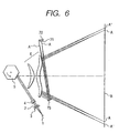
-
Fig. 6 of the accompanying drawings is a schematic view of a scanning optical apparatus according to the prior art. InFig. 6 , a divergent beam emitted from light source means 1 to which an image signal modulated by modulating means has been inputted is made into a substantially parallel light by acollimator lens 2, and enters acylinder lens 4 with the cross-sectional shape of the beam limited by anaperture stop 3. That portion of the parallel beam having entered thecylinder lens 4 which is in the main scanning surface emerges in its state as it is. Also, in the sub-scanning surface, the beam converges and is formed substantially as a linear image on the reflecting surface of alight deflector 5 comprising a polygon mirror. The beam reflected and deflected by the reflecting surface of thelight deflector 5 is directed to a scannedsurface 8 through two imaging optical elements, subsequently also called scanning optical elements (fθ lenses) 6 having an fθ characteristic. Thelight deflector 5 is then rotated in the direction of arrow, whereby the scannedsurface 8 is scanned in the main scanning direction and is scanned in the sub-scanning direction by the next reflecting surface of thelight deflector 5. A part of the beam deflected by thelight deflector 5 is reflected by areflecting mirror 75 through the scanningoptical elements 6 and is directed to aslit 71 and asensor 72, and is synchronized with the writing beginning timing of an image. - In recent years, with the higher resolution and lower cost of image forming apparatuses having the electrophotographic process, it has become the mainstream to manufacture the scanning optical element (fθ lens) of the aforedescribed scanning optical apparatus by plastic molding, and use an inexpensive fθ lens in which chromatic aberration of magnification is not compensated for. Also, in order to cope with highspeed color image formation, there is required a scanning optical apparatus for use in a tandem type color image forming apparatus as shown in
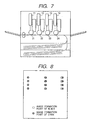
Fig. 7 of the accompanying drawings wherein a plurality of scanning optical apparatuses 11-14 are used at a time correspondingly to four colors, e.g. Y, M, C and K to record image information of each color on each of different photo-sensitive drums 21-24. - However, in the scanning optical apparatus for forming a final image by the beams from the plurality of scanning optical apparatuses, a variation attributable to the chromatic aberration of magnification of the fθ lenses is caused in the scanning magnification among the plurality of scanning optical apparatuses by
- (a) the initial wavelength deviation among the laser light sources of the respective scanning optical apparatuses,
- (b) the wavelength deviation by the mode hopping of semiconductor laser resulting from a change in the environment, and
- (c) the fluctuation of the refractive index of a plastic lens by the change in the environment, and this leads to the deterioration of images.
Fig. 6 of the accompanying drawings shows the image area when the wavelength of the light source of a plurality of scanning optical apparatuses has changed, and the deviation of the imaged position of a beam at a write beginning detecting position. InFig. 6 , there is shown an example in which as indicated at image formation points A and A', the deviations of the image formation points of respective lasers occur on a scannedsurface 8. - Such a deviation of the imaged position on the scanned surface during the variation in the scanning magnification causes a small pixel deviation on the left end side (the lower side in
Fig. 6 ) of the image near the detecting position because in the actual image, as shown inFig. 6 , synchronism is taken at the writing beginning position detecting position, and conversely becomes a great pixel deviation (scanning magnification deviation) on the right end side (the upper side inFig. 6 ) of the image. Consequently, a pixel deviation is caused in the whole of the image printing area, and yet the magnification of the image changes. - This also holds true in a scanning optical system in the tandem type color image forming apparatus, and when a change in magnification occurs among the plurality of scanning optical apparatuses, the image formation point of cyan C and the image formation point of black B coincide with each other on the left end side of the image, as shown in Fig- 8, but the registration deviation (color deviation) among respective colors becomes great on the right end side of the image, and this causes the deterioration of the image. While in
Fig. 8 , color deviations in B (black) and C (cyan) are shown, the same also applies in the case of the color deviation between the other colors Y (yellow) and M (magenta). - It is an object of the present invention to realize a color image forming apparatus using a scanning optical apparatus which reduces the change in the magnification of a scanning optical system by the pixel deviation of the entire printing area in the above-described example of the prior art, or the registration deviation of the scanning optical system in the color image forming apparatus even when an inexpensive plastic molded lens in which the correction of chromatic aberration of magnification is not effected is used as a scanning optical element, and which is low in cost and easy to construct and is small in color deviation.
- This object is achieved by the color image forming apparatus according to claim 1 . The dependent claims relate to further developments.
- The action and effect of the present invention are such that the optical surface of the optical element for synchronous detection is right opposed to a BD beam for detecting a horizontal synchronizing signal, that is, the optical axis of the optical element for synchronous detection and the principal ray of the BD beam are made substantially coincident with each other, whereby the BD beam becomes free from the influence of chromatic aberration of magnification. Also, the chromatic aberration of magnification of the scanning optical system becomes zero on the axis of the scanning optical system, i.e., substantially at the center of the scanning width. Consequently, the on-axis beam substantially at the center of the scanning width which is in predetermined delayed relationship with the BD beam becomes free from the influence of chromatic aberration of magnification, and does not cause pixel deviation.
- Further, if the positional fluctuation of the beam of one or more image heights except at the center of the scanning width is detected, it can be regarded as the fluctuation of the off-axis beam relative to the immovable on-axis beam and therefore, this can be processed as the fluctuation of the scanning magnification or the registration deviation by chromatic aberration of magnification. The processing calculation is done by means of a simple arithmetic expression as described above. Depending on the result of the calculation, timely correction can be applied to thereby achieve a reduction in registration.
-
-
Fig. 1 is a cross-sectional view in the main scanning direction of a scanning optical apparatus according to a first Example. -
Fig. 2 is a cross-sectional view of a scanning optical apparatus according to a second Example in the main scanning direction. -
Fig. 3 shows a tandem type color image forming apparatus according to an embodiment of the present invention. -
Fig. 4 is an output sample by the scanning optical apparatus according to the first Example and shows the state of the magnification deviation in the main scanning direction. -
Fig. 5 is an output sample by the tandem type color image forming apparatus according to the embodiment of the present invention, and shows the State when color deviation has been caused by the magnification deviation in the main scanning direction. -
Fig. 6 is a cross-sectional view of a scanning optical apparatus according to the prior art in the main scanning direction. -
Fig. 7 is a cross-sectional view of a tandem type color image forming apparatus according to the prior art. -
Fig. 8 is the output sample of the scanning optical apparatus according to the prior art, and shows registration deviation in the main scanning direction. -
Fig. 9 is a schematic view of an image forming apparatus according to the present invention. - Some Examples of scanning apparatus and an embodiment of the present invention will hereinafter be described in detail with reference to the drawings.
-
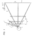
Fig. 1 is a cross-sectional view in the main scanning direction of a scanning optical apparatus according to a first example which may be used in a color image forming apparatus according to the present invention. - In
Fig. 1 , the reference numeral 1 designates light source means modulated by an image signal and comprising, for example, a semiconductor laser (LD). Thereference numeral 2 denotes a collimator lens for converting the beam from the light source means 1 into parallel beams. Thereference numeral 3 designates a stop for limiting the parallel beams from thecollimator lens 2 to a beam (or a predetermined quantity of light) having a predetermined cross-sectional shape. Thereference numeral 4 denotes a cylinder lens for condensing the beam into a linear beam - The
reference numeral 5 designates a light deflector comprising a polygon mirror and rotated in the direction of arrow A by driving means such as a motor, not shown. Thereference numeral 6 denotes a scanning optical system having an fθ characteristic. The reference numeral 7 designates an optical element for synchronous detection (BD lens). Thereference numeral 8 denotes a photosensitive drum which is a scanned surface. - A divergent beam emitted from the semiconductor laser 1 which is light source means is converted into substantially parallel beams by the
collimator lens 2. These beams have their quantities of light limited by thestop 3, and enters thecylinder lens 4. Of these beams, the beam in the main scanning direction is intactly incident on thepolygon mirror 5 which is a light deflector, while the beam in the sub-scanning direction is imaged near the surface of the polygon mirror. Accordingly, the beam incident on thepolygon mirror 5 becomes a linear image long in the main scanning direction. The beam incident on thepolygon mirror 5 which is a light deflector is deflected and scanned in the main scanning direction by the rotation of thepolygon mirror 5 in the direction of arrow A by the motor. - The beam deflected by the
polygon mirror 5 enters the scanningoptical element 6 which is an fθ lens comprising a refracting optical element and a diffracting optical element. In the present embodiment, a plastictoric lens 61 and a long diffractingelement 62 are disposed on thepolygon mirror 5 side with respect to the midpoint of the rotary shaft of thepolygon mirror 5 and the scannedsurface 8. The long diffractingelement 62 is made of plastic made by injection molding, but an equal effect will be obtained even if a diffraction grating is made on a glass substrate by replica. Theseoptical elements polygon mirror 5 to be imaged on the scanned surface and also correct the tilt of the surface of thepolygon mirror 5. The beam having emerged from the scanningoptical element 6 is imaged on the scannedsurface 8, and the scannedsurface 8 comprising a photosensitive member such as a photosensitive drum or the like is scanned in the direction of arrow B by this beam. The photosensitive member such as a photosensitive drum is exposed to this beam, and an image is transferred to transfer paper by way of the known electrophotographic process, thereby forming an image conforming to an image signal inputted to the semiconductor laser 1. - On the other hand, a part (synchronous detection beam) 73 of the beams deflected by the
polygon mirror 5 enters the optical element 7 for synchronous detection. These beams are converged in both of the main scanning and the sub-scanning by the anamorphic power of this element through a reflectingmirror 75, and are imaged and scanned near aslit 71 for synchronous detection, and enter asensor 72 for synchronous detection and produce a synchronizing signal in the main scanning direction. - In the present example, the optical element 7 for synchronous detection singly molded of a plastic material is disposed so that the lens surface thereof may be substantially right opposed to the
synchronous detection beam 73. That is, the optical axis of the optical element 7 for synchronous detection and the principal ray of thesynchronous detection beam 73 are made substantially coincident with each other. Accordingly, as shown inFig. 1 , even if the wavelength of the laser source 1 is changed, for example, by the mode hop by temperature rise, chromatic aberration of magnification is not produced in the optical element 7 for synchronous detection and therefore, the timing of a writing beginning synchronizing signal does not change. Also, even if the refractive index of the optical element 7 for synchronous detection is changed by a change in the environment, the timing of the writing beginning synchronizing signal likewise does not change. - On the other hand, in an image area, if the light source wavelength which is the wavelength of the laser source 1 is changed by a change in the environment such as temperature, humidity and atmospheric pressure of the mode hop or the like by temperature rise, the arrival positions of the beams on the scanned surface coincide with each other only on the optical axis of the scanning optical element, and causes a change in magnification symmetrically on the opposite sides of the optical axis at the other points. This also holds true in the case of the change in refractive index by the fluctuation of the environment.
- That is, the timing of synchronous detection does not change for the change in refractive index by the change in the wavelength or the change in the environment, and the imaged position on the image area changes symmetrically with respect to the optical axis of the scanning optical element and thus, as shown in
Fig. 4 , the amount of change in magnification comes to be produced while being put in two on the writing beginning side and the writing ending side. - So, as shown in
Fig. 1 , the scanning position of an off-axis beam 76 of one-side image height in the main scanning direction on the drum is monitored by scanning position detecting means 90, whereby any change in the scanning magnification (any change in the length of the scanning width) can be detected. In the present Example, the scanning position detecting means 90 is of a type in which the reflectedlight 77 of abeam 76 on the scannedsurface 8 is received and detected, whereas it is not restricted to the type ofFig. 1 , but may use other known method, for example, a method of monitoring an image embodied by the electrophotographic process as used in an embodiment of the present invention. - The scanning position detecting means will hereinafter be described in detail.
- The scanning position detecting means 90 uses a construction in which for example, a predetermined position on the scanned surface 8 (a predetermined image height for measuring the scanning position) and a line CCD (a CCD in which pixels are disposed in a linear state) are disposed in conjugate relationship by an imaging lens and the direction of arrangement of the line CCD is substantially coincident with the scanning direction of the scanning beam. Thereby, the off-axis beam of a predetermined image height having arrived at the scanned
surface 8 is re-imaged on the line CCD through an imaging lens. An output conforming to the quantity of light received by each pixel of the line CCD is monitored, and the pixel of a maximum output or the pixel at the centroid position of the output is specified, whereby the irradiated position on the scannedsurface 8 can be determined. - The scanning beam imaged image height when a predetermined time has elapsed from the timing detected by the synchronous detecting
means 72 is defined as the image height of scanning position detection, and the scanning position detecting means 90 is disposed. - The laser is caused to emit light when a predetermined time has passed from the timing detected by the synchronous detecting
means 72 at each scanning or a predetermined scanning interval, the irradiated position on the scannedsurface 8 based on the scanning position detecting means 90 is determined by a correctingcircuit 200. The case where the irradiated position on the scannedsurface 8 determined at this time has a difference relative to a predetermined position is regarded as a change having been in the irradiated position, and the amount of the change is detected as the amount of fluctuation of the irradiated position. - As another scanning position detecting means 90, a light receiving element like a photodiode is disposed in conjugate relationship with a predetermined position on the scanned surface 8 (a predetermined image height for measuring the scanning position) by an imaging lens. Thereby, the off-axis beam of a predetermined image height having arrived at the scanned
surface 8 is re-imaged on the light receiving element through the imaging lens. An output conforming to the quantity of light received by the light receiving element is monitored, and the timing at which a predetermined quantity of light has been reached is specified, whereby the timing at which the scanning beam has passed the irradiated position on the scannedsurface 8 can be determined. - Irradiated position detecting means is provided at a particular position on the scanned
surface 8. - The timing detected by the synchronous detecting
means 72 and the timing detected by the scanning position detecting means 90 are measured at each scanning or at a predetermined scanning interval, and the time differential therebetween is calculated. The case where the amount of change in the time differential between the two timings calculated at this time has a difference relative to a predetermined value is regarded as a change having been in the irradiated position, and from the amount of the change and the scanning speed of the scanning beam, the amount of fluctuation of the irradiated position is calculated by a correctingcircuit 200. - Next, a change in the scanning magnification detected by monitoring by the scanning position detecting means 90 can be corrected into the original magnification by the existing method described below. That is, it can be corrected into the original magnification in conformity with or in superposition on
- (a) changing the focal length by a zoom Fθ lens,
- (b) changing the rotating speed of the polygon mirror,
- (c) changing the driving frequency of LD, and
- (d) changing the magnification of the image by image processing.
- By correcting and controlling the scanning magnification by the existing means as described above while monitoring by the scanning position detecting means 90, the imaging point after the change of
Fig. 4 can be returned to the initial imaging point. According toFig. 4 , the imaging points of the respective colors can be made coincident with one another on the main axis in the main scanning direction, and the respective color lights can be converged to such a degree that they slightly deviate from one another as they deviate to the right and left points of the main axis. - As described above, in the present example, the optical element 7 for synchronous detection of the scanning optical apparatus is disposed so that the lens surface thereof may be opposed substantially right to the
synchronous detection beam 73, whereby even when an inexpensive plastic-molded lens in which the correction of chromatic aberration of magnification is not effected is used as the scanning optical element, it is possible to reduce the pixel deviation of the scanningoptical system 6 attributable to wavelength deviation or magnification deviation by a change in the environment. - Also, a multilaser having a plurality of light emitting points may be used as the light source in the present embodiment to thereby provide a multibeam scanning optical apparatus, and it is possible to realize a color image forming apparatus which can highly minutely cope with a higher speed.
-
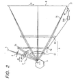
Fig. 2 shows the construction of a second example of a scanning optical apparatus wich may be used in the color image forming apparatus according to the present invention. InFig. 2 , the same reference numerals as those inFig. 1 designate members similar in performance and function to those inFig. 1 . - The differences of the second example from the scanning optical apparatus of the first example are:
- (a) that the scanning position detecting means 90 is provided at an image height downstream of the scanning area; and
- (b) that the
cylinder lens portion 41 and the optical element portion 42 for synchronous detection are made integral with each other to thereby provide acompound lens 40. - The
compound lens 40 is produced by the integral molding step using a mold, and makes a reduction in cost possible. It is also possible to suitably re-set the focal lengths of thecylinder lens portion 41 and the optical element portion 42 for synchronous detection to thereby approximate the disposition of thecompound lens 40 to ascanning lens 61 and further make them integral with each other. By making thecompound lens 40 and thescanning lens 61 integral with each other, the unevenness in disposition can be restrained and a contribution can be made to an improvement in performance. - In the present example, as in the first example, as shown in
Fig. 4 , a scanning position deviation occurs to putting it in two with the on-axis image height as the reference and therefore, even if the scanning position detecting means 90 is provided at the image height opposite to that in the first embodiment, any change in scanning magnification can likewise be detected. - That is, a retrace period is simply provided in a predetermined time after the detection of BD as a synchronizing signal which is the image height downstream of the scanning area of the scanning position detecting means 90 and therefore, the difference from the first example is only to convert the trigger time of timing, and when there is the influence of the scanning position detecting means 90 upon the disposition of the
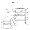
compound lens 40, thecompound lens 40 and the scanning position detecting means 90 for detecting BD at the start of the scanning retrace period may be combined together as shown inFig. 2 , but the two may be disposed discretely from each other when there is no influence upon the integral disposition of thecompound lens 40. - In an embodiment of the present invention, four scanning optical apparatuses except the scanning position detecting means 90 which are identical with the scanning optical apparatus of the first example are juxtaposed in parallel to one another and are used in a tandem type color image recording apparatus for recording an image signal on photosensitive drums which are image bearing members.
-
Fig. 3 shows the above-described tandem type color image forming apparatus. Scanning optical apparatuses 1.1 to 14 correspond to C (cyan), M (magenta), Y (yellow) and B (black), respectively, and image information of each color is recorded on each of differentphotosensitive drums 21 to 24. Such a color image forming apparatus can record and print a color image at a speed as high as that for a black-and-white image, but the scanning optical apparatuses are not used in common for the respective colors and therefore, there is the drawback that the scanning line positions (registration) among the colors are liable to deviate and color deviation is liable to occur. - In the present embodiment, in the scanning optical apparatuses used in the tandem type color image forming apparatus, as in the first example, the optical element 7 for synchronous detection singly molded of a plastic material is disposed so that the lens surface thereof may be opposed substantially right to the synchronizing
detection beam 73. - Accordingly, as in the first example, even if for example, the light source wavelength among the four scanning optical apparatuses changes, the timing of the writing beginning synchronizing signal does not change, and even if the refractive index of the optical element for synchronous detection is changed by a change in the environment, the timing of the writing beginning synchronizing signal likewise does not change.
- On the other hand, in the image area, when the light source wavelength among the four scanning optical apparatuses changes, the arrival positions of the beams on the scanned
surface 8 coincide with each other only on the optical axis of the scanning optical element and at the other points, a change in magnification occurs symmetrically on the opposite sides of the optical axis (this also holds true in the case of a change in refractive index by the fluctuation of the environment). - That is, the synchronous detection timing does not change for the change in refractive index by a change in wavelength or a change in the environment, and the imaged position on the image area changes symmetrically with respect to the optical axis of the scanning optical element and therefore, as shown in
Fig. 5 , an amount of color deviation occurs with the amount of magnification change of each color put in two on the writing beginning side and the writing ending side. According toFig. 5 , as inFig. 8 , the image formation points of cyan (C) and the image formation points of black (B) coincide with each other at the central position on the optical axis, but on the upper left side of the scanning starting point and the upper right side of the end point, the image formation points of cyan (C) deviate more outwardly than the image formation points of black (B). This deviation may equally occur for four colors including M (magenta) and Y (yellow), but the deviation between the image formation points is small because the image formation points are made coincident with each other on the optical axis. - The detection of the amount of deviation of this scanning line position (registration) among the colors is effected as follows. A predetermined marking (Z in
Fig. 3 ) is provided at symmetrical off-axis image heights and image information for each color is recorded as a latent image on each of the differentphotosensitive drums 21 to 24 by each of the four scanning optical apparatuses. Next, the latent image is visualized on a conveyingbelt 26 by an electrophotographic process apparatus, not shown. The amount of deviation of the registration is detected byregistration detecting means - Here, the registration detecting means refers to detecting means for detecting the scanning line position (registration), and the registration deviation refers to the deviation of the scanning line position (registration) in the main scanning direction.
- The registration detecting means will hereinafter be described in detail.
- The construction of the
registration detecting means belt 26, and marking position detecting means for detecting the position of the marking. - The illuminating means is an illuminating optical device for illuminating the marking portion by an emitted beam from a light source such as an LED through the intermediary of a reflector or a condensing lens.
- Also, as the marking position detecting means, use can.be made of the scanning position detecting means 90 in the first or second example. That is, for the detection of the marking position, use is made of a construction in which, like the scanning position detecting means 90, a line CCD (a CCD in which pixels are arranged in a straight line) is disposed in conjugate relationship with the position the marking on the conveying
belt 26 passes (a predetermined image height for measuring the scanning position) by an imaging lens and the arrangement direction of the line CCD is made substantially coincident with the scanning direction of the scanning beam. Thereby, the marking illuminated by the illuminating means is imaged on the line CCD through the imaging lens. An output conforming to the quantity of light received by each pixel of the line CCD is monitored, and the pixel at the centroidal position of the output is specified, whereby the position of the marking in the main scanning direction can be determined. As the method of determining the position of the marking, utilization may be made of any other known method than a method of specifying the pixel at the centroidal position of the CCD output. When the positions of the markings of the respective colors Y, M, C and K are individually detected and there is a relative difference among them, it is regarded as the registration deviation occurring, and the amount of the relative difference is detected as the amount of registration deviation by acorrection circuit 201. - If the amount of registration deviation exceeds a predetermined amount (which is usually said to be 0.1 mm in the case of an A4 format printer), it is considered to be a problem as a degradation in the quality of a color image. A correcting method therefor will be described below.
- When the amount of registration deviation detected by the
registration detecting means 91 is defined as Δ1 and the amount of registration deviation detected by theregistration detecting means 92 is defined as Δ2 and constants are K and K', the amount ΔA of correction of the deviation of writing beginning timing is obtained by effecting the correction control of delaying the writing beginning timing by an amount corresponding to

- The details of the method of correcting the scanning magnification are similar to those in the first embodiment. That is, the scanning magnification can be corrected by adopting one of the following steps or mixing the following steps together: (a) changing the focal length by a zoom F (H) lens; (b) changing the rotational speed of the polygon mirror; (c) changing the driving frequency of LD; and (d) changing the magnification of the image by image processing.
- Also, the constants K and K' are usually "1", but there is a case where they do not always become "1" due to such factors as the elongation of image transferring paper and the individual difference of the apparatus, and they can be set timely.
- The constants K and K' will hereinafter be described in detail.
- K and K' usually are 1. At this time, ΔA is the simple average of Δ1 and Δ2 and therefore is indicative of the amount of deviation of the irradiated position of the central one of the image heights being monitored by the two registration detecting means. Also, ΔA' becomes a half of the difference between Δ1 and Δ2, and is indicative of a half of the change in the interval between the image heights being monitored by the two
registration detecting means - On the other hand, K and K' need not always be 1 if ΔA' is within the allowable range of the deviation of registration. The allowable range of the deviation of registration is varied by the designed apparatus or the outputted image and therefore cannot be defined unconditionally. On the other hand, among the colors Y, M, C and K, some are apt to be conspicuous in the deviation of registration and some are hard to be conspicuous in the deviation of registration. The allowable range is wide for the colors hard to be conspicuous in the deviation of registration and therefore, it is not always necessary to precisely correct the calculated amount of registration deviation, but yet for the colors apt to be conspicuous in the registration deviation, it is desirable to approximate K and K' to 1.
- Also, as another case, it is desirable to timely set K and K' to other constants than 1 correspondingly to the expansion and contraction or conveyance of image transferring paper. Images of the respective colors Y, M, C and K are successively transferred to the image transferring paper, but the transferring paper itself is expanded or contracted by the fluctuation of the pressure and temperature it receives in the meantime. As the result, the transferred image is expanded or contracted by an amount corresponding to some magnification (the magnification deviates). Also, the transferring paper causes so-called zigzag conveyance in which it deviates in a direction perpendicular to the direction of movement thereof when the images of the respective colors Y, M, C and K are successively transferred to the transferring paper. At this time, it becomes necessary to stagger the writing beginning timing to thereby provide the registration deviation of the colors Y, M, C and K.
- The deviation of the writing beginning timing of ΔA occurs when the accuracy of the alignment of the centers of the scanning directions of the four scanning optical apparatuses is bad during the assembly of the color image forming apparatus or the positions of the centers of the scanning directions of the scanning optical apparatuses deviate from one another for some reason or other during the use of the color image forming apparatus.
- The amount registration deviation corresponding to each color can be reduced even if with a reference color (e.g. black) as the reference, the other colors are relatively put together or absolute amounts of deviation are put together for each color.
- As described above, in the present embodiment, the optical elements for synchronous detection of the scanning optical apparatuses used in the tandem type color image forming apparatus are disposed so that the lens surfaces thereof may be opposed substantially right to the synchronous detection beam, whereby even when an inexpensive plastic molded lens in which the correction of chromatic aberration of magnification is not effected is used as the scanning optical element, it is possible to reduce the color deviation of a color image attributable to the magnification deviation by wavelength deviation or a change in the environment. Also, a multilaser having a plurality of light emitting points may be used as the light source in the present embodiment to thereby provide a multibeam scanning optical apparatus, and it is possible to realize a color image forming apparatus which can highly minutely cope with a higher speed.
- Description will now be made of an image forming apparatus applied to the present invention.
-
Fig. 9 is a cross-sectional view of the essential portions of an embodiment of the image forming apparatus of the present invention in the sub-scanning direction. InFig. 9 , thereference numeral 104 designates the image forming apparatus. Code data Dc is inputted from anoutside apparatus 117 such as a personal computer to thisimage forming apparatus 104. This code data Dc is converted into image data (dot data) Di by aprinter controller 111 in the apparatus. This image data Di is inputted to anoptical scanning unit 100 having the construction shown in Embodiments 1 to 3. Alight beam 103 modulated in conformity with the image data Di is emitted from theoptical scanning unit 100, and the photosensitive surface of aphotosensitive drum 101 is scanned in the main scanning direction by thislight beam 103. - The
photosensitive drum 101 which is an electrostatic latent image bearing member (a photosensitive member) is clockwisely rotated by amotor 115. With this rotation, the photosensitive surface of thephotosensitive drum 101 moves in the sub-scanning direction orthogonal to the main scanning direction, relative to thelight beam 103. Above thephotosensitive drum 101, a chargingroller 102 for uniformly charging the surface of thephotosensitive drum 101 is provided so as to contact with the surface of the photosensitive drum. Thelight beam 103 scanned by theoptical scanning unit 100 may be applied to the surface of thephotosensitive drum 101 charged by the chargingroller 102. - As previously described, the
light beam 103 is modulated on the basis of the image data Di, and by thislight beam 103 being applied to the surface of thephotosensitive drum 101, an electrostatic latent image is formed thereon. This electrostatic latent image is developed as a toner image by a developingdevice 107 disposed so as to abut against thephotosensitive drum 101 downstream of the applied position of thelight beam 103 with respect to the rotational direction of thephotosensitive drum 101. - The toner image developed by the developing
device 107 is transferred ontopaper 112 which is a transferring material by a transferringroller 108 disposed below thephotosensitive drum 101 so as to be opposed to thephotosensitive drum 101. Thepaper 112 is contained in apaper cassette 109 forward (on the right side as viewed inFig. 9 ) of thephotosensitive drum 101, and can also be manually fed. Apaper feeding roller 110 is disposed on one end portion of thepaper cassette 109, and feeds thepaper 112 in thepaper cassette 109 to a conveying path. - The
paper 112 to which the unfixed toner image has been transferred in the manner described above is further conveyed to a fixing device rearward (on the left side as viewed inFig. 9 ) of thephotosensitive drum 101. The fixing device is comprised of a fixingroller 113 having a fixing heater (not shown) therein, and apressing roller 114 disposed so as to pressure-contact with the fixingroller 113, and heats thepaper 112 conveyed from the transferring portion while pressing thepaper 112 by the pressure contact portion between the fixingroller 113 and thepressing roller 114, thereby fixing the unfixed toner image on thepaper 112. A pair ofpaper discharging rollers 116 are further disposed rearwardly of the fixingroller 113 and discharge thepaper 112 on which the toner image has been fixed out of the image forming apparatus. - Although not shown in
Fig. 9 , aprinter controller 111 effects not only the conversion of the aforedescribed data, but also the control of various portions in the image forming apparatus including amotor 115 and a polygon motor, etc. in the optical scanning unit which will be described later. - As described above, according to the present invention, even when an inexpensive plastic molded lens in which the correction of chromatic aberration of magnification is not effected is used as the scanning optical element, it is possible to reduce the deviation of the scanning magnification of the scanning optical system by the deviation of magnification attributable to the wavelength deviation between the light sources and the fluctuation of the environment, or the registration deviation of the scanning optical system in the tandem type color image forming apparatus, and realize a scanning optical apparatus which is low in cost and easy to construct and is small in jitter and color deviation, and a color image forming apparatus using the same.
Claims (6)
- A color image forming apparatus for scanning a plurality of beams from at least one scanning optical apparatus (11, 12, 13, 14) on a plurality of image bearing members (21, 22, 23, 24) to thereby form a color image, said scanning optical apparatus comprising:a light source (1);a deflecting element (5) for deflecting and scanning a beam emitted from said light source;a imaging optical element (6) for imaging said deflected beam into a spot shape on the scanned surfaces of said image bearing members; an optical element (7, 42) for synchronous detection for directing the deflected beam from said deflecting element to a sensor (72) for synchronous detection, andregistration detecting means (91, 92) for detecting a positional deviation in the main scanning direction of a marking of a predetermined shape formed on each of said image bearing members by each scanning optical apparatus is provided at a position corresponding to an image height separate from the optical axis of said imaging optical element,characterized in that
the beam traveling towards said sensor does not pass the imaging optical element, and an optical axis of said optical element for synchronous detection is arranged to be coincident with a principal ray of the deflected beam deflected from said deflecting element while being scanned to pass the optical element for synchronous detection. - The apparatus according to claim 7, wherein said registration detecting means (91, 92) is disposed so as to be capable of detecting a plurality of predetermined positions substantially symmetrical in the main scanning direction with respect to the optical axis of said imaging optical element.
- The apparatus according to claim 1 or 2, further comprising provision of correcting means for reducing absolute registration deviation in each scanning optical apparatus (11, 12, 13, 14) or registration deviation relative to the scanning optical apparatus providing the reference, in conformity with the output of said registration detecting means (91, 92).
- The apparatus according to claims 2 or 3, wherein said registration detecting means (91, 92) is disposed so as to be capable of detecting two predetermined positions substantially symmetrical in the main scanning direction with respect to the optical axis of said imaging optical element, and effects the correction control of correcting the timing of image writing beginning by an amount corresponding to

where Δ1 is the amount of registration deviation at a first predetermined position, Δ2 is the amount of registration deviation at a second predetermined position, and K is a constant. - The apparatus according to claims 2 or 3, wherein said registration detecting means (91, 92) is disposed so as to be capable of detecting two predetermined positions substantially symmetrical in the main scanning direction with respect to the optical axis of said imaging optical element, and effects the correction control of correcting the scanning magnification by an amount corresponding to

where Δ1 is the amount of registration deviation at a first predetermined position, Δ2 is the amount of registration deviation at a second predetermined position, and K' is a constant. - A color image forming apparatus according to any one of claims 1 to 5, further comprising a printer controller for converting code data inputted from an external apparatus into an image signal and inputting it to said scanning optical apparatus (11, 12, 13, 14).
Applications Claiming Priority (3)
| Application Number | Priority Date | Filing Date | Title |
|---|---|---|---|
| JP30681499A JP2001125027A (en) | 1999-10-28 | 1999-10-28 | Scanning optical device, and color image forming device using the same |
| JP30681499 | 1999-10-28 | ||
| EP00123545A EP1096292B1 (en) | 1999-10-28 | 2000-10-27 | Optical scanning apparatus and color image forming apparatus using the same |
Related Parent Applications (2)
| Application Number | Title | Priority Date | Filing Date |
|---|---|---|---|
| EP00123545A Division EP1096292B1 (en) | 1999-10-28 | 2000-10-27 | Optical scanning apparatus and color image forming apparatus using the same |
| EP00123545.6 Division | 2000-10-27 |
Publications (2)
| Publication Number | Publication Date |
|---|---|
| EP1494061A1 EP1494061A1 (en) | 2005-01-05 |
| EP1494061B1 true EP1494061B1 (en) | 2008-06-04 |
Family
ID=17961595
Family Applications (2)
| Application Number | Title | Priority Date | Filing Date |
|---|---|---|---|
| EP00123545A Expired - Lifetime EP1096292B1 (en) | 1999-10-28 | 2000-10-27 | Optical scanning apparatus and color image forming apparatus using the same |
| EP04023809A Expired - Lifetime EP1494061B1 (en) | 1999-10-28 | 2000-10-27 | Optical scanning apparatus and color image forming apparatus using the same |
Family Applications Before (1)
| Application Number | Title | Priority Date | Filing Date |
|---|---|---|---|
| EP00123545A Expired - Lifetime EP1096292B1 (en) | 1999-10-28 | 2000-10-27 | Optical scanning apparatus and color image forming apparatus using the same |
Country Status (4)
| Country | Link |
|---|---|
| US (2) | US7015940B1 (en) |
| EP (2) | EP1096292B1 (en) |
| JP (1) | JP2001125027A (en) |
| DE (2) | DE60039134D1 (en) |
Families Citing this family (11)
| Publication number | Priority date | Publication date | Assignee | Title |
|---|---|---|---|---|
| JP2003185952A (en) | 2001-12-19 | 2003-07-03 | Canon Inc | Optical scanner and color image forming apparatus using the same |
| ATE442606T1 (en) | 2003-02-17 | 2009-09-15 | Seiko Epson Corp | SCANNER |
| JP2004302062A (en) * | 2003-03-31 | 2004-10-28 | Canon Inc | Multibeam light scanner |
| JP4745605B2 (en) * | 2003-09-24 | 2011-08-10 | キヤノン株式会社 | Scanning optical apparatus and image forming apparatus |
| JP2005280070A (en) * | 2004-03-29 | 2005-10-13 | Canon Inc | Image forming apparatus and its control method |
| JP3920868B2 (en) | 2004-04-06 | 2007-05-30 | 三星電子株式会社 | Image forming apparatus |
| JP4815363B2 (en) * | 2006-02-20 | 2011-11-16 | 株式会社リコー | Optical scanning apparatus and image forming apparatus |
| JP5106033B2 (en) * | 2007-10-16 | 2012-12-26 | キヤノン株式会社 | Optical scanning device and image forming apparatus using the same |
| JP5375127B2 (en) * | 2008-02-28 | 2013-12-25 | 株式会社リコー | Exposure apparatus, image forming apparatus, and image forming method |
| CN113534448B (en) * | 2021-07-16 | 2022-10-11 | 苏州溢博伦光电仪器有限公司 | Composite scanner for high speed imaging of multiple regions of interest |
| CN113534450B (en) * | 2021-07-16 | 2022-10-14 | 苏州溢博伦光电仪器有限公司 | Mechanical resonance scanning edge blanking device |
Family Cites Families (33)
| Publication number | Priority date | Publication date | Assignee | Title |
|---|---|---|---|---|
| US4829175A (en) * | 1985-12-05 | 1989-05-09 | Fuji Photo Film Co., Ltd. | Light beam scanning apparatus, method of correcting unevenness in scanning lines in light beam scanning apparatus, method of detecting deflection of rotational axis of light beam deflector and rotational axis deflection detecting device |
| DE3884271T2 (en) | 1987-04-28 | 1994-03-31 | Canon Kk | Device for multi-image generation. |
| JP2609626B2 (en) | 1987-09-14 | 1997-05-14 | キヤノン株式会社 | Laser beam printer registration system |
| US5072244A (en) | 1987-11-30 | 1991-12-10 | Canon Kabushiki Kaisha | Superposed image forming apparatus with plural and adjustable image forming stations |
| JP2633877B2 (en) * | 1987-11-30 | 1997-07-23 | キヤノン株式会社 | Image forming device |
| US4833489A (en) * | 1987-12-30 | 1989-05-23 | Samsung Electronics Co., Ltd. | Electrical f·θ correction system in a laser printer |
| DE68916862T2 (en) | 1988-05-27 | 1995-03-02 | Tokyo Electric Co Ltd | Controller of a scanning motor for regulating the speed of rotation of a scanning motor. |
| JPH03110512A (en) | 1989-09-26 | 1991-05-10 | Canon Inc | Light beam scanning device |
| EP0448123B1 (en) * | 1990-03-23 | 2001-08-16 | Canon Kabushiki Kaisha | Scanning optical device |
| US5497184A (en) * | 1990-04-27 | 1996-03-05 | Asahi Kogaku Kogyo Kabushiki Kaisha | Laser scanning system |
| US5043744A (en) * | 1990-05-18 | 1991-08-27 | Xerox Corporation | Raster scanner including scanning beam tilt correction |
| JP3207497B2 (en) * | 1992-03-10 | 2001-09-10 | キヤノン株式会社 | Image forming device |
| JP3315474B2 (en) | 1993-05-13 | 2002-08-19 | 株式会社リコー | Image forming device |
| US5450211A (en) | 1993-06-29 | 1995-09-12 | Minolta Camera Kabushiki Kaisha | Image forming apparatus and method for maintaining set magnification not withstanding changes in optical system due to temperature change |
| DE69520897T2 (en) | 1994-02-03 | 2001-10-18 | Canon Kk | Imaging device |
| JP3291906B2 (en) | 1994-04-11 | 2002-06-17 | キヤノン株式会社 | Scanning optical device |
| US5715498A (en) | 1994-09-16 | 1998-02-03 | Canon Kabushiki Kaisha | Color image forming apparatus and method for forming a color image corrected for aberration in registration of image stations for each color |
| US5486694A (en) * | 1994-12-02 | 1996-01-23 | Xerox Corporation | Wobble correction and focusing optical element with refractive toroidal surface and binary diffractive optical surface |
| JP3286111B2 (en) * | 1995-03-23 | 2002-05-27 | キヤノン株式会社 | Printing apparatus and method |
| JPH08271819A (en) | 1995-03-29 | 1996-10-18 | Nec Corp | Optical scanner |
| JP3231610B2 (en) * | 1995-12-22 | 2001-11-26 | 富士通株式会社 | Color image forming equipment |
| JP2840584B2 (en) | 1996-02-28 | 1998-12-24 | キヤノン株式会社 | Image forming device |
| JP3432085B2 (en) | 1996-08-28 | 2003-07-28 | キヤノン株式会社 | Scanning optical device |
| JP3466841B2 (en) | 1996-11-08 | 2003-11-17 | キヤノン株式会社 | Scanning optical device |
| JP3604852B2 (en) | 1996-12-28 | 2004-12-22 | キヤノン株式会社 | Scanning optical device and laser beam printer |
| JP3595640B2 (en) | 1997-02-07 | 2004-12-02 | キヤノン株式会社 | Scanning optical system and laser beam printer |
| US6172786B1 (en) * | 1997-09-03 | 2001-01-09 | Konica Corporation | Optical deflection device and image forming apparatus therewith |
| JPH11198436A (en) * | 1998-01-14 | 1999-07-27 | Konica Corp | Image-forming apparatus |
| JPH11326804A (en) * | 1998-03-16 | 1999-11-26 | Canon Inc | Color image forming device and scanning optical device |
| JP2000089148A (en) * | 1998-07-13 | 2000-03-31 | Canon Inc | Optical scanner and image forming device using the same |
| JP3087748B2 (en) * | 1998-12-16 | 2000-09-11 | 富士ゼロックス株式会社 | Optical scanning device |
| JP2000330050A (en) * | 1999-03-12 | 2000-11-30 | Canon Inc | Multi-beam scanning optical device and color image forming device |
| JP4006153B2 (en) | 1999-12-14 | 2007-11-14 | キヤノン株式会社 | Multi-beam optical scanning optical system and image forming apparatus using the same |
-
1999
- 1999-10-28 JP JP30681499A patent/JP2001125027A/en active Pending
-
2000
- 2000-10-24 US US09/694,502 patent/US7015940B1/en not_active Expired - Lifetime
- 2000-10-27 DE DE60039134T patent/DE60039134D1/en not_active Expired - Lifetime
- 2000-10-27 EP EP00123545A patent/EP1096292B1/en not_active Expired - Lifetime
- 2000-10-27 EP EP04023809A patent/EP1494061B1/en not_active Expired - Lifetime
- 2000-10-27 DE DE60025565T patent/DE60025565T2/en not_active Expired - Lifetime
-
2005
- 2005-11-23 US US11/285,066 patent/US7365764B2/en not_active Expired - Fee Related
Also Published As
| Publication number | Publication date |
|---|---|
| EP1096292A2 (en) | 2001-05-02 |
| US7365764B2 (en) | 2008-04-29 |
| DE60039134D1 (en) | 2008-07-17 |
| DE60025565D1 (en) | 2006-04-06 |
| US7015940B1 (en) | 2006-03-21 |
| US20060072002A1 (en) | 2006-04-06 |
| JP2001125027A (en) | 2001-05-11 |
| EP1096292B1 (en) | 2006-01-18 |
| DE60025565T2 (en) | 2006-08-10 |
| EP1494061A1 (en) | 2005-01-05 |
| EP1096292A3 (en) | 2002-07-10 |
Similar Documents
| Publication | Publication Date | Title |
|---|---|---|
| US7365764B2 (en) | Scanning optical apparatus and color image forming apparatus using the same | |
| US6771296B2 (en) | Optical scanning device and method for providing specific dot offsets at center and ends of scan width | |
| US7050209B2 (en) | Scanning optical apparatus and image forming apparatus using the same | |
| JP3209656B2 (en) | Optical scanning device | |
| US20030179428A1 (en) | Optical scanner and imaging apparatus using the same | |
| JP2005140922A (en) | Optical scanner, image forming apparatus and correcting method for deviation of position | |
| JP2008225060A (en) | Optical scanning device and image forming apparatus using the same | |
| US8310738B2 (en) | Scanning optical device, image forming device and jitter correction method | |
| JP4015249B2 (en) | Multi-beam exposure system | |
| KR100384431B1 (en) | Multi-beam scanning optical system and image forming apparatus using the same | |
| US6815663B2 (en) | Apparatus for optical scanning along with measurement of optical characteristics within scanning region | |
| KR100856154B1 (en) | Optical scanning apparatus and image-forming apparatus using the same | |
| US7136208B2 (en) | Light scanning apparatus and image forming apparatus using the same | |
| US6856336B2 (en) | Color image forming apparatus with color registration detector | |
| US7031039B2 (en) | Optical scanning apparatus and image forming apparatus using the same | |
| US7830402B2 (en) | Image forming apparatus and image write start position adjusting method for the same | |
| US7274499B2 (en) | Scanning optical apparatus and image forming apparatus using the same | |
| JP2005309336A (en) | Method of optical scanning, optical scanner, method of image forming and image forming apparatus | |
| JP4630593B2 (en) | Scanning optical device and image forming apparatus using the same | |
| JP4612839B2 (en) | Method for adjusting color image forming apparatus | |
| JP2002055295A (en) | Optical scanner | |
| JP2007155837A (en) | Optical scanner and image forming apparatus using the same | |
| JP2003315717A (en) | Optical scanner and image forming apparatus | |
| JP2001242405A (en) | Optical scanner and image-forming device | |
| JP2002048991A (en) | Optical scanner |
Legal Events
| Date | Code | Title | Description |
|---|---|---|---|
| PUAI | Public reference made under article 153(3) epc to a published international application that has entered the european phase |
Free format text: ORIGINAL CODE: 0009012 |
|
| AC | Divisional application: reference to earlier application |
Ref document number: 1096292 Country of ref document: EP Kind code of ref document: P |
|
| AK | Designated contracting states |
Kind code of ref document: A1 Designated state(s): DE FR GB IT NL |
|
| 17P | Request for examination filed |
Effective date: 20050705 |
|
| AKX | Designation fees paid |
Designated state(s): DE FR GB IT NL |
|
| 17Q | First examination report despatched |
Effective date: 20060703 |
|
| GRAP | Despatch of communication of intention to grant a patent |
Free format text: ORIGINAL CODE: EPIDOSNIGR1 |
|
| GRAS | Grant fee paid |
Free format text: ORIGINAL CODE: EPIDOSNIGR3 |
|
| GRAA | (expected) grant |
Free format text: ORIGINAL CODE: 0009210 |
|
| AC | Divisional application: reference to earlier application |
Ref document number: 1096292 Country of ref document: EP Kind code of ref document: P |
|
| AK | Designated contracting states |
Kind code of ref document: B1 Designated state(s): DE FR GB IT NL |
|
| REG | Reference to a national code |
Ref country code: GB Ref legal event code: FG4D |
|
| REF | Corresponds to: |
Ref document number: 60039134 Country of ref document: DE Date of ref document: 20080717 Kind code of ref document: P |
|
| PLBE | No opposition filed within time limit |
Free format text: ORIGINAL CODE: 0009261 |
|
| STAA | Information on the status of an ep patent application or granted ep patent |
Free format text: STATUS: NO OPPOSITION FILED WITHIN TIME LIMIT |
|
| 26N | No opposition filed |
Effective date: 20090305 |
|
| REG | Reference to a national code |
Ref country code: FR Ref legal event code: PLFP Year of fee payment: 16 |
|
| REG | Reference to a national code |
Ref country code: FR Ref legal event code: PLFP Year of fee payment: 17 |
|
| PGFP | Annual fee paid to national office [announced via postgrant information from national office to epo] |
Ref country code: NL Payment date: 20160905 Year of fee payment: 17 |
|
| PGFP | Annual fee paid to national office [announced via postgrant information from national office to epo] |
Ref country code: IT Payment date: 20161005 Year of fee payment: 17 |
|
| REG | Reference to a national code |
Ref country code: FR Ref legal event code: PLFP Year of fee payment: 18 |
|
| REG | Reference to a national code |
Ref country code: NL Ref legal event code: MM Effective date: 20171101 |
|
| PG25 | Lapsed in a contracting state [announced via postgrant information from national office to epo] |
Ref country code: NL Free format text: LAPSE BECAUSE OF NON-PAYMENT OF DUE FEES Effective date: 20171101 |
|
| REG | Reference to a national code |
Ref country code: FR Ref legal event code: PLFP Year of fee payment: 19 |
|
| PG25 | Lapsed in a contracting state [announced via postgrant information from national office to epo] |
Ref country code: IT Free format text: LAPSE BECAUSE OF NON-PAYMENT OF DUE FEES Effective date: 20171027 |
|
| PGFP | Annual fee paid to national office [announced via postgrant information from national office to epo] |
Ref country code: FR Payment date: 20191025 Year of fee payment: 20 |
|
| PGFP | Annual fee paid to national office [announced via postgrant information from national office to epo] |
Ref country code: GB Payment date: 20191029 Year of fee payment: 20 Ref country code: DE Payment date: 20191227 Year of fee payment: 20 |
|
| REG | Reference to a national code |
Ref country code: DE Ref legal event code: R071 Ref document number: 60039134 Country of ref document: DE |
|
| REG | Reference to a national code |
Ref country code: GB Ref legal event code: PE20 Expiry date: 20201026 |
|
| PG25 | Lapsed in a contracting state [announced via postgrant information from national office to epo] |
Ref country code: GB Free format text: LAPSE BECAUSE OF EXPIRATION OF PROTECTION Effective date: 20201026 |