EP1493979A1 - Fahrzeugklimaanlage mit überkritischem Kreislauf - Google Patents
Fahrzeugklimaanlage mit überkritischem Kreislauf Download PDFInfo
- Publication number
- EP1493979A1 EP1493979A1 EP04013750A EP04013750A EP1493979A1 EP 1493979 A1 EP1493979 A1 EP 1493979A1 EP 04013750 A EP04013750 A EP 04013750A EP 04013750 A EP04013750 A EP 04013750A EP 1493979 A1 EP1493979 A1 EP 1493979A1
- Authority
- EP
- European Patent Office
- Prior art keywords
- initial value
- air
- air conditioning
- temperature
- fluid
- Prior art date
- Legal status (The legal status is an assumption and is not a legal conclusion. Google has not performed a legal analysis and makes no representation as to the accuracy of the status listed.)
- Withdrawn
Links
Images


Classifications
-
- F—MECHANICAL ENGINEERING; LIGHTING; HEATING; WEAPONS; BLASTING
- F25—REFRIGERATION OR COOLING; COMBINED HEATING AND REFRIGERATION SYSTEMS; HEAT PUMP SYSTEMS; MANUFACTURE OR STORAGE OF ICE; LIQUEFACTION SOLIDIFICATION OF GASES
- F25B—REFRIGERATION MACHINES, PLANTS OR SYSTEMS; COMBINED HEATING AND REFRIGERATION SYSTEMS; HEAT PUMP SYSTEMS
- F25B9/00—Compression machines, plants or systems, in which the refrigerant is air or other gas of low boiling point
- F25B9/002—Compression machines, plants or systems, in which the refrigerant is air or other gas of low boiling point characterised by the refrigerant
- F25B9/008—Compression machines, plants or systems, in which the refrigerant is air or other gas of low boiling point characterised by the refrigerant the refrigerant being carbon dioxide
-
- F—MECHANICAL ENGINEERING; LIGHTING; HEATING; WEAPONS; BLASTING
- F25—REFRIGERATION OR COOLING; COMBINED HEATING AND REFRIGERATION SYSTEMS; HEAT PUMP SYSTEMS; MANUFACTURE OR STORAGE OF ICE; LIQUEFACTION SOLIDIFICATION OF GASES
- F25B—REFRIGERATION MACHINES, PLANTS OR SYSTEMS; COMBINED HEATING AND REFRIGERATION SYSTEMS; HEAT PUMP SYSTEMS
- F25B2309/00—Gas cycle refrigeration machines
- F25B2309/06—Compression machines, plants or systems characterised by the refrigerant being carbon dioxide
- F25B2309/061—Compression machines, plants or systems characterised by the refrigerant being carbon dioxide with cycle highest pressure above the supercritical pressure
-
- F—MECHANICAL ENGINEERING; LIGHTING; HEATING; WEAPONS; BLASTING
- F25—REFRIGERATION OR COOLING; COMBINED HEATING AND REFRIGERATION SYSTEMS; HEAT PUMP SYSTEMS; MANUFACTURE OR STORAGE OF ICE; LIQUEFACTION SOLIDIFICATION OF GASES
- F25B—REFRIGERATION MACHINES, PLANTS OR SYSTEMS; COMBINED HEATING AND REFRIGERATION SYSTEMS; HEAT PUMP SYSTEMS
- F25B2500/00—Problems to be solved
- F25B2500/26—Problems to be solved characterised by the startup of the refrigeration cycle
-
- F—MECHANICAL ENGINEERING; LIGHTING; HEATING; WEAPONS; BLASTING
- F25—REFRIGERATION OR COOLING; COMBINED HEATING AND REFRIGERATION SYSTEMS; HEAT PUMP SYSTEMS; MANUFACTURE OR STORAGE OF ICE; LIQUEFACTION SOLIDIFICATION OF GASES
- F25B—REFRIGERATION MACHINES, PLANTS OR SYSTEMS; COMBINED HEATING AND REFRIGERATION SYSTEMS; HEAT PUMP SYSTEMS
- F25B2600/00—Control issues
- F25B2600/17—Control issues by controlling the pressure of the condenser
Definitions
- the invention relates to air conditioning installations, in particular the passenger compartment of a vehicle.
- Such air conditioning systems are provided with a refrigerant circuit comprising a compressor, a gas cooler, a detent, and a evaporator traveled in this order by the refrigerant.
- supercritical refrigerants such as CO2
- CO2 supercritical refrigerants
- Air conditioning circuits operating with a supercritical fluid generally use an expansion device of the electronic expansion valve type.
- An electronic expansion valve comprises an adjustable opening valve according to the intensity of a control signal. The flow of fluid at the outlet of the electronic expansion valve then varies depending on the signal strength control and consequently the cooling performance of the air conditioning loop depend on the intensity of this control signal.
- the intensity the control signal of the detent is controlled by the regulator of air conditioner.
- the controller of the air conditioning system when starting the air conditioning, the controller of the air conditioning system by default sets the initial intensity of the control signal which acts on the initial opening of valve. Since this initial intensity does not take into account the actual conditions of operation of the air-conditioning system, it sometimes triggers an opening too weak of the regulator and consequently, an overpressure at the outlet of the regulator. This overpressure can cause the maximum power to be exceeded and thus cause a overconsumption of the engine at start-up and in particular an overpressure with a rise very fast pressure. Conversely, when the initial value triggers an opening Too big the regulator, the high pressure slowly increases and the power refrigerant can be insufficient.
- the invention improves the situation.
- the electronic control device is suitable for calculating estimating the target value of the high pressure from the initial value of the fluid temperature at the outlet of the gas cooler.
- the electronic control device is able to calculate an estimate of the value initial temperature of the fluid output gas cooler from the value initial air temperature at the inlet of the gas cooler.
- the initial value of the fluid temperature at the inlet of the expansion member can be estimated from the initial value of the airflow temperature upstream of the gas cooler.
- the installation may include a probe placed in the path of the airflow upstream of the gas cooler, able to provide the initial value of the airflow temperature in upstream gas cooler.
- the electronic control device is capable of to estimate the initial value of the refrigerant flow in the expansion orifice from the initial value of the refrigerant flow in the compressor.
- the electronic control device is capable of estimating the initial value of the flow rate of refrigerant in the compressor from the target value of the high pressure, the initial value of the pressure of the refrigerant at the outlet of the expansion element and the initial speed of rotation of the compressor.
- the installation may include a sensor capable of providing the initial value the pressure of the fluid at the outlet of the expansion orifice.
- the electronic control device is able to transmit the initial value of the signal the air conditioning regulator, the air conditioning regulator being adapted to apply said initial value of the control signal for a shorter duration or equal to 10 seconds.
- the invention also covers a product program, which can be defined as including the functions used to estimate the power absorbed by the compressor.
- Appendix A contains the main mathematical equations used to implement implement the installation.
- the compressor 14 may be an electric or mechanical compressor.
- the cooling member 11 receives a flow of air 16 to evacuate the heat taken from the refrigerant, which under certain operating conditions is set in motion by a fan motor unit 15.
- the evaporator 13 receives an air stream 18 from a blower 20 and produces a flow of conditioned air which is sent to the passenger compartment of the vehicle.
- the air conditioning circuit of Figure 1 operates in a supercritical cycle.
- the air conditioning circuit is traversed by a supercritical refrigerant, for example the CO2 refrigerant.
- a supercritical refrigerant for example the CO2 refrigerant.
- high pressure to high temperature is above the critical pressure of the fluid.
- the body of cooling 11 is an external cooler ("gas cooler").
- the internal heat exchanger 9 allows the circulating fluid of the gas cooler 11 to the regulator to give heat to the fluid flowing from the evaporator to the compressor.
- the detent 12 is an orifice whose section varies according to the intensity of a PWM control signal, hereinafter referred to as an "electronic expander”.
- FIG. 2 is a diagram showing an air conditioning installation according to the invention, set up in a motor vehicle.
- the vehicle is equipped with the air conditioning 10 described with reference to Figure 1.
- the installation is furthermore provided with an air conditioning computer 40, comprising a cockpit controller 41 and an air conditioning loop controller 402.
- the regulator cabin 41 is intended to set the temperature of the pulsed air at the entry of the evaporator 13.
- the air conditioning regulator 402 imposes a default value of the the initial PWM_init control signal without taking into account the actual conditions of operation. This initial value then controls an initial opening of the orifice of relaxation, not optimized with respect to actual operating conditions that may have as a result overconsumption of the engine or a cooling capacity insufficient.
- the air conditioning installation according to the invention proposes to optimize the initialization of the opening of the detent device taking into account the actual conditions of operation.
- French Patent Application No. 0206724 establishes a relationship between the flow rate of refrigerant m CO2_OD in the electronic expander and the pressure of the fluid Pin at the inlet of the electronic expander, the pressure of the fluid Pout at the outlet of the electronic expander, the temperature Tin in input of the electronic holder and the PWM intensity of the control signal, in a circuit operating in a supercritical cycle. This relationship is given in Part A1 of Appendix A.
- the present invention proposes to optimize the initialization of the electronic expander from the above-mentioned relation linking the PWM intensity, the flow rate of refrigerant in the expansion orifice m CO2_OD , the temperature Tin, the pressure Pout and the pressure Pin .
- the cockpit regulator 41 and the air conditioning circuit 10 are connected to a device control electronics, for example an electronic card 401 for an exchange information.
- the electronic card 401 is programmed to solve the equations that allow to obtain an estimate of the initial intensity of the PWM_init control signal.
- the electronic card 401 can be arranged to transmit the information that results these estimates to the injection computer of the vehicle, when the vehicle is equipped.
- the air conditioning loop controller 402 having in particular the role of adapting the amount of heat taken from the passenger compartment, said power refrigerant, to reach the setpoint of air temperature blown at the exit of the evaporator or the reference of the cabin sensor.
- the cabin controller 41 exchanges information with the climate control unit relative to the air setpoint blown at the outlet of the evaporator.
- the electronic card 401 retrieves information 30 from sensors installed. on the air conditioning unit.
- FIG. 3 is a diagram illustrating the influence of the control PWM signal on the rate of opening of the electronic expansion valve 12. This figure shows that the rate of opening of the electronic expansion valve is a decreasing function of the PWM control signal.
- a weak initial PWM_init intensity will trigger a very large opening of the section passage of the regulator and consequently insufficient cooling capacity because the high pressure is too low.
- a high initial PWM_init intensity will trigger a very small opening of the regulator passage section and consequently an overpressure important when starting the air conditioning loop.
- FIG. 4 represents the steps of the estimation of the initial value of the PWM control intensity.
- the electronic card When the electronic card detects in step 100 that the air conditioning A / C is actuated, and in step 101 that the compressor is running, it performs steps 102 to 114 for estimate the initial intensity of the PWM_init control signal.
- step 102 the electronic card recovers the temperature of the air Tai at the inlet of the gas cooler 11.
- the temperature Tai of the air upstream of the gas cooler can be measured by a probe 200 placed on the path of the air flow entering the gas cooler 11.
- the temperature Tai can be estimated by the electronic card, from the instantaneous values of the forward speed Va of the vehicle and the temperature of the air outside the vehicle Text.
- the forward speed Va is available on the vehicle. It can be provided by example by the engine computer or the air conditioning computer.
- the installation may include a temperature probe that provides a measure of the Text temperature of the air outside the vehicle.
- step 104 the electronic card then determines the temperature Tgco of the CO2 fluid, at the outlet of the gas cooler 11 from the value of the temperature of the air flow in upstream of the Tai gas cooler.
- the plaintiff has observed that choosing the temperature Tgco equal to the temperature of the air flow upstream of the gas cooler, the initialization of the expansion orifice is improved.
- step 106 the electronic card measures an initial value Pout_init of the pressure of the CO2 fluid, at the outlet of the regulator, before starting the compressor.
- This pressure can be measured by a sensor 202 placed at the outlet of the gas cooler 11.
- the electronic card estimates the initial value of the Tin_init temperature of the CO2 fluid at the inlet of the regulator from the difference between the initial value of the Tai air temperature upstream of the gas cooler and an optimal value of the temperature of the air blown at the outlet of the evaporator Tt, according to equation (4) of Annex A.
- This value is chosen to optimize the comfort in the passenger compartment and to meet the user's cold demand.
- the temperature value Tt is taken equal to 10 ° C. This value may vary by plus or minus 5 ° C, without this modifying substantially the calculated value of the intensity of the PWM_init control signal.
- step 110 the electronic card estimates a target value Pin_vrise of the pressure of the CO2 fluid at the inlet of the regulator which allows to obtain optimal conditions of operation.
- This value Pin_vrise is calculated from the temperature Tgco obtained in step 104, in accordance with equation (5) of Appendix A.
- the value Pin_vrise allows maximize the coefficient of performance COP.
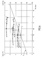
- FIG. 6 illustrates the relationship linking the fluid pressure to the inlet of the expansion device Pin_vised and the coefficient of performance COP.
- the optimum value of fluid pressure at the input of the expansion element Pin_vrise corresponds to a coefficient of performance maximum.
- the Applicant has determined that for a given temperature Tgco output of the gas cooler, there is a value of the Pin_vrise pressure which maximizes the coefficient of performance according to equation (5) of Annex A.
- curves a ', b' and c 'in broken lines represent the evolution of the fluid pressure at the inlet of the expansion orifice Pin as a function of the Tgco fluid temperature for three different outdoor conditions.
- step 112 the electronic board estimates the initial value of the flow of refrigerant M CO2_OD_ init in the expansion orifice. This value of the flow must make it possible to obtain an optimal high pressure and corresponds to the flow of fluid sucked by the compressor at startup.
- the flow rate of refrigerant in the compressor is related to the compressor capacity C y , the high pressure, the low pressure and the speed of rotation of the compressor N, according to equation (3) of Appendix A.
- the parameters k3 and k4 are constants that characterize the degradation of the volumetric efficiency as a function of the compression ratio. For example k3 can be of the order of 0.95 to 0.96 and k4 of the order of 0.85.
- Pin_vrise high pressure is provided in step 110 and the low Pout_init is supplied in step 106.
- the compressor At startup, the compressor is in maximum displacement and in this case the cylinder capacity Cy is known.
- the initial value of the rotation speed N0 is available on the vehicle. She can be provided for example by the engine computer.
- the electronic card can therefore calculate the fluid flow rate for a compressor in maximum cubic capacity according to this equation.
- Equation (1) in Appendix A gives the general form of the relationship between fluid flow refrigerant in the expansion orifice at the temperature of the fluid entering the Tin regulator, the fluid pressure at the inlet of the Pin expander, the fluid pressure at the outlet of the expander Pout, and the intensity of the PWM control signal.
- the function k is a characteristic defining the opening of the expander 12 as a function of the PWM current supplied to the valve.
- ⁇ 0 is the density of the fluid at the inlet of the expander and is estimated from the temperature of the fluid entering the expansion orifice Tin and the pressure of the fluid entering the expansion orifice Pin, according to the relation (2) of Annex A.
- step 114 the electronic card solves equation (1) of Annex A from the operating conditions at the start of the air conditioning, ie from the initial value of the fluid pressure Pout_init at the input of the the expansion orifice obtained in step 106, the initial value of the temperature of the fluid at the inlet of the Tin_init expansion orifice obtained in step 108, the target value of the fluid pressure Pin_vrise calculated at the step 110, and the initial value of the flow of refrigerant in the expansion member m CO2_OD_init estimated at step 112.
- This equation provides the initial intensity PWM_init of the command signal from the CO2 electronic expansion valve. This intensity is transmitted to the regulator of 402 which uses it to initialize the electronic expansion valve 12. This value will be applied only at start-up for a predefined period of time between 3 and About 10 seconds.
- FIG. 5 illustrates the effects of the initialization of the electronic expansion valve according to the invention.
- curve represented by small squares represents the evolution of the outlet pressure of the regulator as a function of time in the air conditioning system of the invention.
- curve in solid line represents the evolution of the pressure output of the regulator as a function of time, according to an embodiment of the prior art where the initial intensity of the PWM signal is chosen by default.
- the initialization of the electronic expansion valve proposed by the air conditioning system according to the invention is particularly useful when the vehicle is idling, when the starting the air conditioning and at high temperature. In these circumstances, there is effect a risk of overpressure which may lead to exceeding the maximum pressure on duty.
- the present invention also aims at the software code that it involves, while especially when it is made available on any support readable on a computer.
- computer-readable medium covers a storage medium, for example magnetic or optical, as well as a transmission means, such as a signal digital or analog.
Landscapes
- Engineering & Computer Science (AREA)
- Chemical & Material Sciences (AREA)
- Chemical Kinetics & Catalysis (AREA)
- Physics & Mathematics (AREA)
- Mechanical Engineering (AREA)
- Thermal Sciences (AREA)
- General Engineering & Computer Science (AREA)
- Air-Conditioning For Vehicles (AREA)
Applications Claiming Priority (2)
| Application Number | Priority Date | Filing Date | Title |
|---|---|---|---|
| FR0307902A FR2856782B1 (fr) | 2003-06-30 | 2003-06-30 | Installation de climatisation de vehicule fonctionnant selon un cycle supercritique |
| FR0307902 | 2003-06-30 |
Publications (1)
| Publication Number | Publication Date |
|---|---|
| EP1493979A1 true EP1493979A1 (de) | 2005-01-05 |
Family
ID=33427641
Family Applications (1)
| Application Number | Title | Priority Date | Filing Date |
|---|---|---|---|
| EP04013750A Withdrawn EP1493979A1 (de) | 2003-06-30 | 2004-06-11 | Fahrzeugklimaanlage mit überkritischem Kreislauf |
Country Status (2)
| Country | Link |
|---|---|
| EP (1) | EP1493979A1 (de) |
| FR (1) | FR2856782B1 (de) |
Cited By (4)
| Publication number | Priority date | Publication date | Assignee | Title |
|---|---|---|---|---|
| FR2895787A1 (fr) * | 2006-01-04 | 2007-07-06 | Valeo Systemes Thermiques | Installation de climatisation parcourue par un fluide supercritique |
| WO2008026115A1 (fr) * | 2006-09-01 | 2008-03-06 | Valeo Systemes Thermiques | Installation de climatisation à cycle supercritique |
| FR2913102A1 (fr) * | 2007-02-28 | 2008-08-29 | Valeo Systemes Thermiques | Installation de climatisation equipee d'une vanne de detente electrique |
| WO2011056371A3 (en) * | 2009-11-03 | 2011-08-18 | Carrier Corporation | Pressure spike reduction for refrigerant systems incorporating a microchannel heat exchanger |
Families Citing this family (1)
| Publication number | Priority date | Publication date | Assignee | Title |
|---|---|---|---|---|
| CN100362294C (zh) * | 2005-12-19 | 2008-01-16 | 东莞市广大制冷有限公司 | 螺杆冷水精密空调系统的控制方法 |
Citations (9)
| Publication number | Priority date | Publication date | Assignee | Title |
|---|---|---|---|---|
| EP0837291A2 (de) * | 1996-08-22 | 1998-04-22 | Denso Corporation | Kälteanlage des Dampfkompressionstyps |
| US6182456B1 (en) * | 1998-04-20 | 2001-02-06 | Denso Corporation | Supercritical refrigerating cycle system |
| JP2001091070A (ja) * | 1999-09-24 | 2001-04-06 | Denso Corp | 超臨界冷凍サイクル |
| US6230506B1 (en) * | 1998-08-24 | 2001-05-15 | Denso Corporation | Heat pump cycle system |
| WO2001063185A1 (fr) * | 2000-02-25 | 2001-08-30 | Zexel Valeo Climate Control Corporation | Cycle frigorifique |
| JP2002022288A (ja) * | 2000-07-13 | 2002-01-23 | Zexel Valeo Climate Control Corp | 冷凍サイクル制御装置 |
| JP2002022299A (ja) * | 2000-07-07 | 2002-01-23 | Calsonic Kansei Corp | 冷房サイクル |
| US6505476B1 (en) * | 1999-10-28 | 2003-01-14 | Denso Corporation | Refrigerant cycle system with super-critical refrigerant pressure |
| FR2833886A1 (fr) * | 2001-12-20 | 2003-06-27 | Valeo Climatisation | Installation de climatisation de vehicule munie d'un dispositif electronique de controle |
-
2003
- 2003-06-30 FR FR0307902A patent/FR2856782B1/fr not_active Expired - Fee Related
-
2004
- 2004-06-11 EP EP04013750A patent/EP1493979A1/de not_active Withdrawn
Patent Citations (9)
| Publication number | Priority date | Publication date | Assignee | Title |
|---|---|---|---|---|
| EP0837291A2 (de) * | 1996-08-22 | 1998-04-22 | Denso Corporation | Kälteanlage des Dampfkompressionstyps |
| US6182456B1 (en) * | 1998-04-20 | 2001-02-06 | Denso Corporation | Supercritical refrigerating cycle system |
| US6230506B1 (en) * | 1998-08-24 | 2001-05-15 | Denso Corporation | Heat pump cycle system |
| JP2001091070A (ja) * | 1999-09-24 | 2001-04-06 | Denso Corp | 超臨界冷凍サイクル |
| US6505476B1 (en) * | 1999-10-28 | 2003-01-14 | Denso Corporation | Refrigerant cycle system with super-critical refrigerant pressure |
| WO2001063185A1 (fr) * | 2000-02-25 | 2001-08-30 | Zexel Valeo Climate Control Corporation | Cycle frigorifique |
| JP2002022299A (ja) * | 2000-07-07 | 2002-01-23 | Calsonic Kansei Corp | 冷房サイクル |
| JP2002022288A (ja) * | 2000-07-13 | 2002-01-23 | Zexel Valeo Climate Control Corp | 冷凍サイクル制御装置 |
| FR2833886A1 (fr) * | 2001-12-20 | 2003-06-27 | Valeo Climatisation | Installation de climatisation de vehicule munie d'un dispositif electronique de controle |
Non-Patent Citations (5)
| Title |
|---|
| KAUF F: "Determination of the optimum high pressure for transcritical CO2-refrigeration cycles", INTERNATIONAL JOURNAL OF THERMAL SCIENCES, EDITIONS ELSEVIER, PARIS, FR, vol. 38, no. 4, April 1999 (1999-04-01), pages 325 - 330, XP004420780, ISSN: 1290-0729 * |
| LIAO S M ET AL: "A CORRELATION OF OPTIMAL HEAT REJECTION PRESSURES IN TRANSCRITICAL CARBON DIOXIDE CYCLES", CLEAN STEEL: SUPERCLEAN STEEL. CONFERENCE PROCEEDINGS, XX, XX, vol. 20, 2000, pages 831 - 841, XP001172861 * |
| PATENT ABSTRACTS OF JAPAN vol. 2000, no. 21 3 August 2001 (2001-08-03) * |
| PATENT ABSTRACTS OF JAPAN vol. 2002, no. 05 3 May 2002 (2002-05-03) * |
| ZHU M S ET AL: "RESEARCHES ON THE CO2 TRANSCRITICAL R/AC/HP SYSTEM IN CHINA", IIR GUSTAV LORENTZEN CONFERENCE ON NATURAL WORKING FLUIDS. JOINT CONFERENCE OF THE INTERNATIONAL INSTITUTE OF REFRIGERATION SECTION B AND E, XX, XX, 17 September 2002 (2002-09-17), pages 24 - 30, XP001176571 * |
Cited By (10)
| Publication number | Priority date | Publication date | Assignee | Title |
|---|---|---|---|---|
| FR2895787A1 (fr) * | 2006-01-04 | 2007-07-06 | Valeo Systemes Thermiques | Installation de climatisation parcourue par un fluide supercritique |
| EP1806548A1 (de) * | 2006-01-04 | 2007-07-11 | Valeo Systèmes Thermiques | Klimaanlage, durch die ein superkritisches Fluid fliesst |
| WO2008026115A1 (fr) * | 2006-09-01 | 2008-03-06 | Valeo Systemes Thermiques | Installation de climatisation à cycle supercritique |
| FR2905450A1 (fr) * | 2006-09-01 | 2008-03-07 | Valeo Systemes Thermiques | Installation de climatisation a cycle supercritique. |
| FR2913102A1 (fr) * | 2007-02-28 | 2008-08-29 | Valeo Systemes Thermiques | Installation de climatisation equipee d'une vanne de detente electrique |
| EP1965156A1 (de) * | 2007-02-28 | 2008-09-03 | Valeo Systèmes Thermiques | Klimaanlage mit elektrischem Entspannungsventil |
| US9341398B2 (en) | 2007-02-28 | 2016-05-17 | Valeo Systemes Thermiques | Air conditioning system provided with an electronic expansion valve |
| WO2011056371A3 (en) * | 2009-11-03 | 2011-08-18 | Carrier Corporation | Pressure spike reduction for refrigerant systems incorporating a microchannel heat exchanger |
| US20120167602A1 (en) * | 2009-11-03 | 2012-07-05 | Taras Michael F | Pressure spike reduction for refrigerant systems incorporating a microchannel heat exchanger |
| US10107535B2 (en) * | 2009-11-03 | 2018-10-23 | Carrier Corporation | Pressure spike reduction for refrigerant systems incorporating a microchannel heat exchanger |
Also Published As
| Publication number | Publication date |
|---|---|
| FR2856782A1 (fr) | 2004-12-31 |
| FR2856782B1 (fr) | 2005-09-23 |
Similar Documents
| Publication | Publication Date | Title |
|---|---|---|
| EP1965156B1 (de) | Klimaanlage mit elektrischem Entspannungsventil | |
| EP1806547A1 (de) | Entspannungsmodul für Klimaanlage mit zwei Verdampfern | |
| EP1456045B1 (de) | Mit einer elektronischen steuervorrichtung ausgestattete kraftfahrzeug-klimaanlage | |
| FR2815397A1 (fr) | Dispositif de climatisation de vehicule utilisant un cycle supercritique | |
| EP1112872B1 (de) | Klimaanlage für ein Kraftfahrzeug mit einer optimierten Ventilationssteuerung | |
| EP1493979A1 (de) | Fahrzeugklimaanlage mit überkritischem Kreislauf | |
| EP1687161B1 (de) | Fahrzeugklimaanlagenanordnung | |
| EP1403107B1 (de) | Klimaanlage mit einer elektronischen Überwachungsvorrichtung | |
| EP2651674B1 (de) | System und verfahren zur steuerung eines klimaanlagensystems für ein kraftfahrzeug | |
| EP1509417B1 (de) | Fahrzeugklimaanlageneinheit mit elektronischer steuervorrichtung | |
| FR3077377A1 (fr) | Procede de controle d'un systeme de traitement thermique d'un element d'une chaine de traction electrique de vehicule | |
| EP2699434B1 (de) | Verfahren zur regelung einer klimaanlage in einer fahrgastzelle eines fahrzeuges | |
| EP1806548B1 (de) | Klimaanlage, durch die ein superkritisches Fluid fliesst | |
| FR3082786A1 (fr) | Procede de controle d’un circuit de fluide refrigerant pour vehicule | |
| EP1536193A1 (de) | Entspannungsvorrichtung mit integrierter Elektronik für einen Kältekreislauf eines Klimagerätes insbesondere eines Kraftfahrzeuges | |
| WO2003099597A2 (fr) | Systeme et procede de regulation d'une installation de climatisation | |
| EP3747080B1 (de) | Verfahren zum kühlen einer stromspeichervorrichtung eines fahrzeugs | |
| FR2959005A1 (fr) | Procede de detection du givre sur un echangeur et procede de controle d'une boucle | |
| EP3765318A1 (de) | Verfahren und system zur steuerung eines thermischen regelsystems eines kraftfahrzeugs | |
| EP0911622B1 (de) | Verfahren und Gerät zur Bestimmung der von einem Motor an einer Klimaanlage abgegebenen Leistung und deren Anwendungen | |
| WO2014095591A1 (fr) | Systeme de regulation electrique d'une detente d'un fluide refrigerant et procede de commande d'un tel systeme | |
| WO2017103373A1 (fr) | Procede de pilotage d'un compresseur pour systeme de climatisation d'un vehicule automobile | |
| WO2004005059A1 (fr) | Installation de climatisation munie d’un dispositif electronique de controle | |
| WO2014095592A1 (fr) | Systeme de regulation d'une detente d'un fluide refrigerant |
Legal Events
| Date | Code | Title | Description |
|---|---|---|---|
| PUAI | Public reference made under article 153(3) epc to a published international application that has entered the european phase |
Free format text: ORIGINAL CODE: 0009012 |
|
| AK | Designated contracting states |
Kind code of ref document: A1 Designated state(s): AT BE BG CH CY CZ DE DK EE ES FI FR GB GR HU IE IT LI LU MC NL PL PT RO SE SI SK TR |
|
| AX | Request for extension of the european patent |
Extension state: AL HR LT LV MK |
|
| 17P | Request for examination filed |
Effective date: 20050523 |
|
| AKX | Designation fees paid |
Designated state(s): AT BE BG CH CY CZ DE DK EE ES FI FR GB GR HU IE IT LI LU MC NL PL PT RO SE SI SK TR |
|
| STAA | Information on the status of an ep patent application or granted ep patent |
Free format text: STATUS: THE APPLICATION IS DEEMED TO BE WITHDRAWN |
|
| 18D | Application deemed to be withdrawn |
Effective date: 20080101 |