EP1493962A2 - High pressure valve for hydrogen gas and decompression device for hydrogen gas - Google Patents
High pressure valve for hydrogen gas and decompression device for hydrogen gas Download PDFInfo
- Publication number
- EP1493962A2 EP1493962A2 EP04015220A EP04015220A EP1493962A2 EP 1493962 A2 EP1493962 A2 EP 1493962A2 EP 04015220 A EP04015220 A EP 04015220A EP 04015220 A EP04015220 A EP 04015220A EP 1493962 A2 EP1493962 A2 EP 1493962A2
- Authority
- EP
- European Patent Office
- Prior art keywords
- valve
- pilot
- high pressure
- valve seat
- valve body
- Prior art date
- Legal status (The legal status is an assumption and is not a legal conclusion. Google has not performed a legal analysis and makes no representation as to the accuracy of the status listed.)
- Granted
Links
Images



Classifications
-
- F—MECHANICAL ENGINEERING; LIGHTING; HEATING; WEAPONS; BLASTING
- F17—STORING OR DISTRIBUTING GASES OR LIQUIDS
- F17C—VESSELS FOR CONTAINING OR STORING COMPRESSED, LIQUEFIED OR SOLIDIFIED GASES; FIXED-CAPACITY GAS-HOLDERS; FILLING VESSELS WITH, OR DISCHARGING FROM VESSELS, COMPRESSED, LIQUEFIED, OR SOLIDIFIED GASES
- F17C13/00—Details of vessels or of the filling or discharging of vessels
- F17C13/04—Arrangement or mounting of valves
-
- F—MECHANICAL ENGINEERING; LIGHTING; HEATING; WEAPONS; BLASTING
- F17—STORING OR DISTRIBUTING GASES OR LIQUIDS
- F17C—VESSELS FOR CONTAINING OR STORING COMPRESSED, LIQUEFIED OR SOLIDIFIED GASES; FIXED-CAPACITY GAS-HOLDERS; FILLING VESSELS WITH, OR DISCHARGING FROM VESSELS, COMPRESSED, LIQUEFIED, OR SOLIDIFIED GASES
- F17C2205/00—Vessel construction, in particular mounting arrangements, attachments or identifications means
- F17C2205/03—Fluid connections, filters, valves, closure means or other attachments
- F17C2205/0302—Fittings, valves, filters, or components in connection with the gas storage device
- F17C2205/0323—Valves
- F17C2205/0326—Valves electrically actuated
-
- F—MECHANICAL ENGINEERING; LIGHTING; HEATING; WEAPONS; BLASTING
- F17—STORING OR DISTRIBUTING GASES OR LIQUIDS
- F17C—VESSELS FOR CONTAINING OR STORING COMPRESSED, LIQUEFIED OR SOLIDIFIED GASES; FIXED-CAPACITY GAS-HOLDERS; FILLING VESSELS WITH, OR DISCHARGING FROM VESSELS, COMPRESSED, LIQUEFIED, OR SOLIDIFIED GASES
- F17C2205/00—Vessel construction, in particular mounting arrangements, attachments or identifications means
- F17C2205/03—Fluid connections, filters, valves, closure means or other attachments
- F17C2205/0302—Fittings, valves, filters, or components in connection with the gas storage device
- F17C2205/0382—Constructional details of valves, regulators
-
- F—MECHANICAL ENGINEERING; LIGHTING; HEATING; WEAPONS; BLASTING
- F17—STORING OR DISTRIBUTING GASES OR LIQUIDS
- F17C—VESSELS FOR CONTAINING OR STORING COMPRESSED, LIQUEFIED OR SOLIDIFIED GASES; FIXED-CAPACITY GAS-HOLDERS; FILLING VESSELS WITH, OR DISCHARGING FROM VESSELS, COMPRESSED, LIQUEFIED, OR SOLIDIFIED GASES
- F17C2221/00—Handled fluid, in particular type of fluid
- F17C2221/01—Pure fluids
- F17C2221/012—Hydrogen
-
- F—MECHANICAL ENGINEERING; LIGHTING; HEATING; WEAPONS; BLASTING
- F17—STORING OR DISTRIBUTING GASES OR LIQUIDS
- F17C—VESSELS FOR CONTAINING OR STORING COMPRESSED, LIQUEFIED OR SOLIDIFIED GASES; FIXED-CAPACITY GAS-HOLDERS; FILLING VESSELS WITH, OR DISCHARGING FROM VESSELS, COMPRESSED, LIQUEFIED, OR SOLIDIFIED GASES
- F17C2223/00—Handled fluid before transfer, i.e. state of fluid when stored in the vessel or before transfer from the vessel
- F17C2223/01—Handled fluid before transfer, i.e. state of fluid when stored in the vessel or before transfer from the vessel characterised by the phase
- F17C2223/0107—Single phase
- F17C2223/0123—Single phase gaseous, e.g. CNG, GNC
-
- F—MECHANICAL ENGINEERING; LIGHTING; HEATING; WEAPONS; BLASTING
- F17—STORING OR DISTRIBUTING GASES OR LIQUIDS
- F17C—VESSELS FOR CONTAINING OR STORING COMPRESSED, LIQUEFIED OR SOLIDIFIED GASES; FIXED-CAPACITY GAS-HOLDERS; FILLING VESSELS WITH, OR DISCHARGING FROM VESSELS, COMPRESSED, LIQUEFIED, OR SOLIDIFIED GASES
- F17C2223/00—Handled fluid before transfer, i.e. state of fluid when stored in the vessel or before transfer from the vessel
- F17C2223/03—Handled fluid before transfer, i.e. state of fluid when stored in the vessel or before transfer from the vessel characterised by the pressure level
- F17C2223/035—High pressure (>10 bar)
-
- F—MECHANICAL ENGINEERING; LIGHTING; HEATING; WEAPONS; BLASTING
- F17—STORING OR DISTRIBUTING GASES OR LIQUIDS
- F17C—VESSELS FOR CONTAINING OR STORING COMPRESSED, LIQUEFIED OR SOLIDIFIED GASES; FIXED-CAPACITY GAS-HOLDERS; FILLING VESSELS WITH, OR DISCHARGING FROM VESSELS, COMPRESSED, LIQUEFIED, OR SOLIDIFIED GASES
- F17C2223/00—Handled fluid before transfer, i.e. state of fluid when stored in the vessel or before transfer from the vessel
- F17C2223/03—Handled fluid before transfer, i.e. state of fluid when stored in the vessel or before transfer from the vessel characterised by the pressure level
- F17C2223/036—Very high pressure (>80 bar)
-
- F—MECHANICAL ENGINEERING; LIGHTING; HEATING; WEAPONS; BLASTING
- F17—STORING OR DISTRIBUTING GASES OR LIQUIDS
- F17C—VESSELS FOR CONTAINING OR STORING COMPRESSED, LIQUEFIED OR SOLIDIFIED GASES; FIXED-CAPACITY GAS-HOLDERS; FILLING VESSELS WITH, OR DISCHARGING FROM VESSELS, COMPRESSED, LIQUEFIED, OR SOLIDIFIED GASES
- F17C2270/00—Applications
- F17C2270/01—Applications for fluid transport or storage
- F17C2270/0165—Applications for fluid transport or storage on the road
- F17C2270/0168—Applications for fluid transport or storage on the road by vehicles
-
- F—MECHANICAL ENGINEERING; LIGHTING; HEATING; WEAPONS; BLASTING
- F17—STORING OR DISTRIBUTING GASES OR LIQUIDS
- F17C—VESSELS FOR CONTAINING OR STORING COMPRESSED, LIQUEFIED OR SOLIDIFIED GASES; FIXED-CAPACITY GAS-HOLDERS; FILLING VESSELS WITH, OR DISCHARGING FROM VESSELS, COMPRESSED, LIQUEFIED, OR SOLIDIFIED GASES
- F17C2270/00—Applications
- F17C2270/01—Applications for fluid transport or storage
- F17C2270/0165—Applications for fluid transport or storage on the road
- F17C2270/0184—Fuel cells
-
- Y—GENERAL TAGGING OF NEW TECHNOLOGICAL DEVELOPMENTS; GENERAL TAGGING OF CROSS-SECTIONAL TECHNOLOGIES SPANNING OVER SEVERAL SECTIONS OF THE IPC; TECHNICAL SUBJECTS COVERED BY FORMER USPC CROSS-REFERENCE ART COLLECTIONS [XRACs] AND DIGESTS
- Y02—TECHNOLOGIES OR APPLICATIONS FOR MITIGATION OR ADAPTATION AGAINST CLIMATE CHANGE
- Y02E—REDUCTION OF GREENHOUSE GAS [GHG] EMISSIONS, RELATED TO ENERGY GENERATION, TRANSMISSION OR DISTRIBUTION
- Y02E60/00—Enabling technologies; Technologies with a potential or indirect contribution to GHG emissions mitigation
- Y02E60/30—Hydrogen technology
- Y02E60/32—Hydrogen storage
-
- Y—GENERAL TAGGING OF NEW TECHNOLOGICAL DEVELOPMENTS; GENERAL TAGGING OF CROSS-SECTIONAL TECHNOLOGIES SPANNING OVER SEVERAL SECTIONS OF THE IPC; TECHNICAL SUBJECTS COVERED BY FORMER USPC CROSS-REFERENCE ART COLLECTIONS [XRACs] AND DIGESTS
- Y10—TECHNICAL SUBJECTS COVERED BY FORMER USPC
- Y10T—TECHNICAL SUBJECTS COVERED BY FORMER US CLASSIFICATION
- Y10T137/00—Fluid handling
- Y10T137/7722—Line condition change responsive valves
- Y10T137/7758—Pilot or servo controlled
- Y10T137/7761—Electrically actuated valve
-
- Y—GENERAL TAGGING OF NEW TECHNOLOGICAL DEVELOPMENTS; GENERAL TAGGING OF CROSS-SECTIONAL TECHNOLOGIES SPANNING OVER SEVERAL SECTIONS OF THE IPC; TECHNICAL SUBJECTS COVERED BY FORMER USPC CROSS-REFERENCE ART COLLECTIONS [XRACs] AND DIGESTS
- Y10—TECHNICAL SUBJECTS COVERED BY FORMER USPC
- Y10T—TECHNICAL SUBJECTS COVERED BY FORMER US CLASSIFICATION
- Y10T137/00—Fluid handling
- Y10T137/7722—Line condition change responsive valves
- Y10T137/7758—Pilot or servo controlled
- Y10T137/7762—Fluid pressure type
-
- Y—GENERAL TAGGING OF NEW TECHNOLOGICAL DEVELOPMENTS; GENERAL TAGGING OF CROSS-SECTIONAL TECHNOLOGIES SPANNING OVER SEVERAL SECTIONS OF THE IPC; TECHNICAL SUBJECTS COVERED BY FORMER USPC CROSS-REFERENCE ART COLLECTIONS [XRACs] AND DIGESTS
- Y10—TECHNICAL SUBJECTS COVERED BY FORMER USPC
- Y10T—TECHNICAL SUBJECTS COVERED BY FORMER US CLASSIFICATION
- Y10T137/00—Fluid handling
- Y10T137/8593—Systems
- Y10T137/86928—Sequentially progressive opening or closing of plural valves
- Y10T137/86936—Pressure equalizing or auxiliary shunt flow
- Y10T137/86944—One valve seats against other valve [e.g., concentric valves]
- Y10T137/86984—Actuator moves both valves
-
- Y—GENERAL TAGGING OF NEW TECHNOLOGICAL DEVELOPMENTS; GENERAL TAGGING OF CROSS-SECTIONAL TECHNOLOGIES SPANNING OVER SEVERAL SECTIONS OF THE IPC; TECHNICAL SUBJECTS COVERED BY FORMER USPC CROSS-REFERENCE ART COLLECTIONS [XRACs] AND DIGESTS
- Y10—TECHNICAL SUBJECTS COVERED BY FORMER USPC
- Y10T—TECHNICAL SUBJECTS COVERED BY FORMER US CLASSIFICATION
- Y10T137/00—Fluid handling
- Y10T137/8593—Systems
- Y10T137/87917—Flow path with serial valves and/or closures
Definitions
- the present invention relates to a high pressure valve for hydrogen gas and a decompression device for hydrogen gas. More particularly, the present invention pertains to a high pressure valve for hydrogen gas and a decompression device for hydrogen gas that are suitable for use in a high-pressure hydrogen gas tank for automobiles driven by a fuel cell.
- a high-pressure hydrogen gas tank for an automobile driven by a fuel cell is filled with hydrogen gas at a pressure of 35 MPa.
- a high pressure valve for hydrogen gas attached to the high-pressure hydrogen gas tank for example, an electromagnetic valve or a pressure reducing valve is used.
- the pressure reducing valve reduces the pressure of high-pressure hydrogen gas discharged from the electromagnetic valve to a particular pressure (e.g. 1 MPa).
- a semi-pilot type valve is known in the art.
- the semi-pilot type valve is switched between an open state and a closed state in accordance with the excitation or de-excitation of a solenoid. In the open state, a pilot valve is separated from a pilot valve seat. In the closed state, the pilot valve contacts the pilot valve seat. When the pilot valve opens, a main valve body separates from a main valve seat to open the valve.
- the pressure reducing valve typically includes a valve hole connected to a pressure reducing chamber, which is defined between a body and a diaphragm.
- a pressure reducing valve includes a valve body, which selectively contacts a valve seat located around the valve hole.
- a valve shaft is connected to the center of the diaphragm. The valve body and the valve shaft are coaxially secured to each other.
- Material for the pilot valve and the pilot valve seat in the electromagnetic valve and material for the valve body and the valve seat in the pressure reducing valve are selected as required without any design limitation.
- the pilot valve, the pilot valve seat, the valve body, and the valve seat can withstand a high pressure of 35 MPa and maintains the sealing effectiveness even when the valves are closed.
- the high-pressure hydrogen gas tank for an automobile driven by a fuel cell in these days is aimed to be filled with hydrogen gas at a higher pressure such as a pressure of 70 MPa. Therefore, if the prior art electromagnetic valve and the pressure reducing valve are actually used in the tank for hydrogen gas having higher pressure, sufficient sealing effectiveness cannot be maintained.
- a high pressure valve for hydrogen gas includes a valve seat and a valve member.
- the valve member is movable to selectively open and close the valve seat.
- One of the valve member and the valve seat is formed of austenitic stainless steel, and the other one of the valve member and the valve seat is formed of flexible synthetic resin or soft metal.
- the present invention also provides a pressure reducing valve used to reduce the pressure in a tank containing hydrogen gas.
- the pressure reducing valve includes a valve body, a diaphragm, and a valve member.
- the valve body and the diaphragm define a pressure reducing chamber that includes a valve hole provided with a valve seat.
- the valve member is located to selectively contact the valve seat.
- the valve member is connected to the diaphragm, and the diaphragm is displaced in accordance with the pressure in the pressure reducing chamber.
- the valve member selectively opens and closes the valve hole in accordance with the displacement of the diaphragm.
- the present invention provides a decompression device for connection to a high pressure hydrogen tank.
- the decompression device includes an electromagnetic valve connectable to the high pressure hydrogen tank and a pressure reducing valve connected to the electromagnetic valve for emitting decompressed hydrogen gas to the exterior via the electromagnetic valve and the pressure reducing valve.
- the electromagnetic valve includes a solenoid, a main valve seat, a pilot valve seat, a main valve body, and a pilot valve body.
- the main valve body is switchable between a closed state, where the main valve body contacts the main valve seat, and an open state, where the main valve body is separated from the main valve seat.
- the pilot valve body is switchable between a closed state, where the pilot valve body contacts the pilot valve seat, and an open state, where the pilot valve body is separated from the pilot valve seat.
- the pilot valve body is switched between the open state and the closed state in accordance with excitation and de-excitation of the solenoid.
- the main valve body switches from the closed state to the open state when the pilot valve body is switched from the closed state to the open state.
- the pressure reducing valve includes a valve body and a diaphragm.
- the valve body and the diaphragm define a pressure reducing chamber.
- the pressure reducing chamber includes a valve hole provided with a valve seat, and a valve member located to selectively contact the valve seat.
- the valve member is connected to the diaphragm.
- the diaphragm is displaced in accordance with the pressure in the pressure reducing chamber.
- the valve member selectively opens and closes the valve hole in accordance with the displacement of the diaphragm.
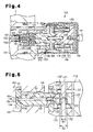
- a high pressure valve for hydrogen gas and a decompression device 10 for hydrogen gas (hereinafter, referred to as a decompression device) according to one embodiment of the present invention will now be described with reference to Figs. 1 to 6.
- the high pressure valve for hydrogen gas is applied to an electromagnetic valve 100 and a pressure reducing valve 400.
- the decompression device includes the electromagnetic valve 100 and the pressure reducing valve 400.
- the decompression device 10 shown in Fig. 1 is mounted to a high-pressure hydrogen gas container, which is a high-pressure hydrogen tank T in this embodiment.
- the tank T is filled with hydrogen gas at a high pressure (70 MPa in this embodiment).
- the decompression device 10 includes an electromagnetic valve 100, a stop valve 300, and a pressure reducing valve 400.
- a stop valve 300 is open when high-pressure hydrogen gas is used.
- the pressure reducing valve 400 reduces the pressure of high-pressure hydrogen gas to a pressure of less than or equal to 1 MPa and discharges the hydrogen gas.
- the electromagnetic valve 100 is located on the end wall of the high-pressure hydrogen tank T.
- a mounting member 101 is attached to the end wall of the high-pressure hydrogen tank T and extends through the end wall.
- a main valve seat mounting bore 102, a guide member mounting bore 103, a plunger accommodating hole 104, and an electromagnetic portion accommodating bore 105 are coaxially formed at the inner end of the mounting member 101 along the axial direction in this order from the section close to the outside of the tank T toward the inside of the tank T.
- the inner diameters of the main valve seat mounting bore 102, the guide member mounting bore 103, the plunger accommodating hole 104, and the electromagnetic portion accommodating bore 105 increase in this order.
- a coil accommodating member 106 is secured to the electromagnetic portion accommodating bore 105.
- the coil accommodating member 106 includes an outer cylinder portion 107 and a core 108, which extends in the outer cylinder portion 107 along the axial direction.
- the outer cylinder portion 107 and the core 108 are integrally formed with magnetic material.
- An annular accommodating groove 109 which is formed between the outer cylinder portion 107 and the core 108, accommodates an annular solenoid coil 110.
- the solenoid coil 110 is electrically connected to a connector 111 located at the outer end of the mounting member 101.
- a control current is supplied to the solenoid coil 110 from a controller (not shown) through the connector 111 to excite the solenoid coil 110.
- a plunger 112 is accommodated in the plunger accommodating hole 104 to freely slide along the axial direction.
- the proximal end of the plunger 112 located in the electromagnetic portion accommodating bore 105 has a larger diameter than the rest of the plunger 112.
- Spring accommodating bores 113, 114 are formed at the proximal end of the plunger 112 and the center of the core 108, respectively.
- the spring accommodating bores 113, 114 face each other.
- the ends of a coil spring 115 are accommodated in the spring accommodating bores 113, 114.
- the coil spring 115 urges the plunger 112 in a direction to close the valve (leftward as viewed in Figs. 2 and 4).
- the solenoid coil 110 When the solenoid coil 110 is excited, the plunger 112 moves in a direction to open the valve (rightward as viewed in Figs. 2 and 4) against the force of the coil spring 115.
- a pair of projections 120 are formed at the distal end of the plunger 112.
- the projections 120 are separate from each other.
- the projections 120 extend through and support a support pin 121.
- a valve member which is a pilot valve 122 in this embodiment, is loosely inserted through the support pin 121 between the projections 120. That is, a support hole 123 is formed in the pilot valve 122 and extends in a direction perpendicular to the axial direction of the pilot valve 122.
- the support pin 121 is inserted in the support hole 123.
- the diameter of the support pin 121 is smaller than the inner diameter of the support hole 123. In this manner, the pilot valve 122 is supported opposite to the plunger 112 with play along the operational direction of the plunger 112.
- the distal end of the pilot valve 122 is formed to be a truncated circular cone and includes a tapered surface 124.
- the pilot valve 122 is formed of SUS316L stainless steel specified in Japanese Industrial Standard JIS G 4304 (Hot rolled stainless steel plates, sheets and strip)-4305 (Cold rolled stainless steel plates, sheets and strip).
- SUS316L is austenitic stainless steel containing 16-18% chromium (Cr), 12-15% nickel (Ni), 2-3% molybdenum (Mo), and carbon (C) less than or equal to 0.03%.
- SUS316L is stainless steel that has high resistance to hydrogen brittleness and has excellent corrosion resistance.
- the dimensional tolerance of the pilot valve 122 is less than or equal to 1 ⁇ m and the surface roughness is less than or equal to 1 ⁇ mRa.
- Both ends of the support pin 121 protruding from the projections 120 support a valve member, which is a main valve body 130 in this embodiment.
- the proximal end of the main valve body 130 is formed as a cylinder portion 131.
- a pair of support holes 132 are formed in the cylinder portion 131.
- the inner diameter of each support hole 132 is greater than the outer diameter of the support pin 121.
- the support holes 132 are formed opposite to each other. Therefore, the main valve body 130 is supported opposite to the plunger 112 with play along the operational direction of the plunger 112.
- the inner diameter of the cylinder portion 131 is greater than the distance between the outer surfaces of the pair of projections 120. This forms a gap G1 in the cylinder portion 131 that serves as a flow passage for hydrogen gas.
- a notch (not shown) is formed in the outer circumference of the cylinder portion 131.
- a gap (not shown) is formed between the notch and the inner circumferential surface of the plunger accommodating hole 104 forming a flow passage for hydrogen gas.
- the support pin 121 contacts the pilot valve 122 before the main valve body 130 when the plunger 112 operates to open the valve.
- the diameters of the middle section and the distal end of the main valve body 130 are smaller than that of the proximal end and extend into the guide member mounting bore 103.
- a pilot bore 133 is formed through the main valve body 130 and extends in the axial direction between the inner bottom surface of the cylinder portion 131 and the distal end of the main valve body 130.
- the main valve body 130 is formed of SUS316L stainless steel.
- the distal end of the main valve body 130 is formed to be a truncated circular cone and includes a tapered surface 139.
- the dimensional tolerance of the main valve body 130 is less than or equal to 1 ⁇ m and the surface roughness is less than or equal to 1 ⁇ mRa.
- a step 138 is formed in the pilot bore 133 close to the inner bottom surface of the cylinder portion 131.
- the diameter of the step 138 is greater than the diameter of the pilot bore 133.
- a pilot valve seat 134 is located in the step 138.
- the pilot valve seat 134 is formed of a flexible polyimide resin.
- the polyimide resin for example, a commercially available VESPEL (registered trademark of DuPont) may be used.
- the dimensional tolerance of the pilot valve seat 134 is less than or equal to 1 ⁇ m and the surface roughness is less than or equal to 1 ⁇ mRa.
- the pilot valve seat 134 has a bore 135, the diameter of which is the same as that of the pilot bore 133, and a pilot valve hole 137, which selectively contacts the tapered surface 124 of the pilot valve 122.
- the pilot valve hole 137 includes a tapered surface 136 the inner diameter of which increases toward the pilot valve 122.
- a cylindrical guide member 140 is screwed to the inner circumference of the guide member mounting bore 103.
- the inner diameter of the guide member 140 is greater than the outer diameter of the main valve body 130.
- a gap G2 is formed between the guide member 140 and the main valve body 130, which forms a flow passage for hydrogen gas.
- a main valve seat support member 150 is inserted into and secured to the main valve seat mounting bore 102.
- a through hole 151 extends through the main valve seat support member 150 in the axial direction.
- the through hole 151 is connected to a passage 160 formed along the axis of the mounting member 101.
- the downstream end of the passage 160 corresponds to a port P2 at the valve-outlet of the electromagnetic valve 100 (see Fig. 2).
- a step 161 is formed in the through hole 151 at the end of the main valve seat support member 150 that faces the guide member 140.
- the diameter of the step 161 is greater than that of the through hole 151.
- a main valve seat 162 is located in the step 161.
- the main valve seat 162 is formed of polyimide resin, which is flexible and is a synthetic resin that is softer than SUS316L stainless steel.
- the example of the polyimide resin includes the above mentioned VESPEL (registered trademark of DuPont).
- the dimensional tolerance of the main valve seat 162 is preferably less than or equal to 1 ⁇ m and the surface roughness is preferably less than or equal to 1 ⁇ mRa.
- a main valve hole 170 is formed in the main valve seat 162.
- the main valve hole 170 includes a bore 163 and a tapered surface 165.
- the diameter of the bore 163 is smaller than that of the through hole 151.
- the inner diameter of the main valve hole 170 at the tapered surface 165 increases toward the main valve body 130.
- the tapered surface 165 selectively contacts the tapered surface 139 of the main valve body 130.
- a passage 180 is formed between the inner circumferential surface of the plunger accommodating hole 104 of the mounting member 101 and the outer circumferential surface of the mounting member 101 extending in the radial direction.
- the passage 180 connects the plunger accommodating hole 104 and the inside of the high-pressure hydrogen tank T.
- the outer circumferential surface of the inner end of the mounting member 101 and the opening of the electromagnetic portion accommodating bore 105 are covered with a cylindrical cover 190.
- the cover 190 is fastened to the coil accommodating member 106 with a bolt 191.
- An opening 180a which corresponds to the inlet of the passage 180, is formed on the outer circumferential surface of the mounting member 101.
- Holes 192 are formed in the circumferential surface of the cover 190 corresponding to the opening 180a, and a filter 193 is placed to cover the holes 192.
- the opening 180a corresponds to a port P1 at the valve-inlet of the electromagnetic valve 100 (see Fig. 2).
- a groove 112a is formed in the circumferential surface of a portion of the plunger 112 that is accommodated in the plunger accommodating hole 104.
- the groove 112a extends along the axial direction such that the groove 112a always faces the inner end of the passage 180 corresponding to the outlet of the passage 180 during valve closing and valve opening operations.
- a notch (not shown) is formed in the plunger 112 at a section closer to the distal end than the groove 112a and extends in the axial direction.
- a gap (not shown) is formed between the notch and the inner circumferential surface of the plunger accommodating hole 104 forming a flow passage for hydrogen gas.
- hydrogen gas in the high-pressure hydrogen tank T can flow through the filter 193, the holes 192, the passage 180, the groove 112a, the gap between the plunger 112 and the plunger accommodating hole 104, and the gap G1 (see Fig. 5). Furthermore, hydrogen gas in the high-pressure hydrogen tank T can flow through the gap between the plunger 112 and the plunger accommodating hole 104, the gap between the cylinder portion 131 and the plunger accommodating hole 104, and the gap G2 (see Fig. 5).
- the plunger 112 When the solenoid coil 110 is de-excited, the plunger 112 is pressed by the force of the coil spring 115 toward the valve closing direction. The force of the coil spring 115 is transmitted to the main valve body 130 via the support pin 121. Thus, the main valve body 130 is in a closed state where the main valve body 130 contacts the main valve seat 162. At this time, the pilot valve 122 is also in a closed state where the pilot valve 122 contacts the pilot valve seat 134. When a control current is supplied to the solenoid coil 110 from a controller (not shown) through the connector 111 in this state, the solenoid coil 110 is excited. As a result, the plunger 112 moves in a valve opening direction.
- the support pin 121 moves by a distance corresponding to the difference ⁇ r2 between the outer diameter R1 of the support pin 121 and the inner diameter R3 of the inner support hole 123, the support pin 121 contacts the pilot valve 122.
- the pilot valve 122 therefore moves with the support pin 121 and separates from the pilot valve seat 134.
- the plunger 112 is pressed by the force of the coil spring 115 toward the valve closing direction.
- the force of the coil spring 115 is transmitted to the pilot valve 122 and the main valve body 130 via the support pin 121.
- the pilot valve 122 is restored to the closed state where the pilot valve 122 contacts the pilot valve seat 134
- the main valve body 130 is restored to the closed state where the main valve body 130 contacts the main valve seat 162.
- the pressure reducing valve 400 is located at the outer end of the mounting member 101.
- a valve housing 401 of the pressure reducing valve 400 is formed with the distal end of the mounting member 101 and a cover 402, which is fastened to the side surface of the mounting member 101 with a bolt (not shown).
- the periphery of a metal diaphragm 403 is held between the cover 402 and the mounting member 101.
- a recess 405 having a circular cross-section is formed on one side of a valve body, which is the mounting member 101 in this embodiment, corresponding to the diaphragm 403.
- a pressure reducing chamber 404 is defined between the diaphragm 403 and the recess 405.
- a mounting bore 406 having a bottom wall is formed in the mounting member 101.
- the mounting bore 406 is open to the pressure reducing chamber 404.
- the mounting bore 406 includes a female screw portion 406a formed in the innermost section of the mounting bore 406 and a fitting bore 406b located at the vicinity of the opening of the mounting bore 406.
- the diameter of the fitting bore 406b is greater than that of the female screw portion 406a.
- the bottom of the mounting bore 406 is connected to a passage 410 for hydrogen gas discharged from the stop valve 300.
- a valve member accommodating member which is a valve seat retaining member 407 in this embodiment, is screwed to the female screw portion 406a of the mounting bore 406.
- the valve seat retaining member 407 is formed in a cylindrical form with SUS316L stainless steel.
- a valve chamber 408 is defined between the valve seat retaining member 407 and the innermost section of the mounting bore 406.
- the valve chamber 408 is connected to the passage 410.
- a contact point between the passage 410 and the valve chamber 408 corresponds to a port P3 at the valve-inlet of the pressure reducing valve 400.
- a flange 411 is formed at the end of the valve seat retaining member 407 and is located in the pressure reducing chamber 404. The flange 411 is engaged with the peripheral portion of the fitting bore 406b.
- a sealing member 412 is fitted in a groove formed in the circumferential surface of the valve seat retaining member 407 corresponding to the fitting bore 406b.
- the sealing member 412 seals between the valve seat retaining member 407 and the inner circumferential surface of the fitting bore 406b.
- a threaded bore 413, a valve seat mounting bore 414, a slide bore 415, and an opening 416 are formed along the central axis of the valve seat retaining member 407 in an order starting from the section close to the pressure reducing chamber 404 toward the valve chamber 408.
- a female screw is formed on the inner circumferential surface of the threaded bore 413.
- a cylindrical valve shaft guide member 417 is screwed to the threaded bore 413.
- the valve shaft guide member 417 includes a guide hole 418 having a circular cross-section.
- the guide hole 418 extends in the axial direction.
- a communication hole 420 which is connected to the guide hole 418, is formed in a bottom wall 419 of the valve shaft guide member 417.
- the diameter of the communication hole 420 is smaller than that of the guide hole 418.
- a step 414a is formed in the valve seat mounting bore 414. Therefore, the valve seat mounting bore 414 includes a large diameter portion, which is closer to the valve shaft guide member 417 than the step 414a, and a small diameter portion, which is closer to the slide bore 415 than the step 414a.
- a valve seat 421 is fitted to the valve seat mounting bore 414 and is engaged with the step 414a.
- the valve seat 421 includes a valve hole 423, which is connected to the communication hole 420 and a central hole of the annular member 422.
- the opening of the valve hole 423 facing the slide bore 415 widens toward the slide bore 415, thereby forming a tapered seat portion 424.
- the valve seat 421 is formed of polyimide resin, which is synthetic resin softer than SUS316L stainless steel.
- the example of the polyimide resin includes VESPEL (registered trademark of DuPont).
- the dimensional tolerance of the main valve seat 421 is preferably less than or equal to 1 ⁇ m and the surface roughness is preferably less than or equal to 1 ⁇ mRa.
- a valve body 425 is accommodated in the slide bore 415 such that the valve body 425 can freely slide in the slide bore 415.
- the valve body 425 serves as a valve member, which selectively contacts the seat portion 424.
- the outer diameter of the valve body 425 is smaller than the inner diameter of the slide bore 415. Therefore, a gap is formed between the inner circumferential surface of the slide bore 415 and the outer circumferential surface of the valve body 425 forming a passage for hydrogen gas (for the convenience of explanation, the gap is not shown in Fig. 6).
- the valve body 425 is formed in a cylindrical form with SUS316L stainless steel.
- the dimensional tolerance of the valve body 425 is less than or equal to 1 ⁇ m and the surface roughness is less than or equal to 1 ⁇ mRa.
- a coating having a low friction coefficient made of TiN is formed on the surface of the valve body 425 through physical vapor deposition (PVD) coating.
- Sealing is not formed between the outer circumferential surface of the valve body 425 and the slide bore 415 of the valve seat retaining member 407 at a sealless portion M shown in Fig. 6. In other words, no sealing member is attached to either the'valve body 425 or the valve seat retaining member 407 at the sealless portion M.
- the inner diameter of the opening 416 is slightly greater than that of the slide bore 415 and a locking step 426 is formed in the opening 416.
- a C-ring 427 is engaged with the opening 416.
- a filter member 428 is secured between the C-ring 427 and the locking step 426.
- a coil spring 430 is located between the filter member 428 and the valve body 425. The coil spring 430 urges the valve body 425 toward the seat portion 424.
- the distal end of the valve body 425 is tapered such that the distal end fits to the tapered seat portion 424.
- a valve shaft 431 is accommodated in the guide hole 418 of the valve shaft guide member 417 to freely slide along the axial direction.
- the valve shaft 431 is integrally coupled with the distal end of the valve body 425 via a coupling shaft 432.
- the diameter of the coupling shaft 432 is smaller than the valve hole 423 and the communication hole 420. That is, the valve shaft 431 and the valve body 425 are integrated when the coupling shaft 432, which extends from the valve body 425, is screwed to the valve shaft 431.
- the valve shaft 431 has a rectangular cross-section. Therefore, a gap'is formed between the valve shaft 431 and the guide hole 418, which has a circular cross-section.
- a flange 433 is formed at the proximal end of the valve shaft 431.
- a flange 434 is also formed at the end of the valve shaft guide member 417 and is located in the pressure reducing chamber 404.
- the flanges 433, 434 contact each other when the valve body 425 is open.
- Grooves (not shown) are formed on the surface of the flange 434 to extend in the radial direction. The grooves permit hydrogen gas to flow into the pressure reducing chamber 404 even when the flanges 434, 433 contact each other.
- a spring chamber 440 is formed between the cover 402 and the diaphragm 403.
- a pair of first and second spring support members 450, 451 are located in the spring chamber 440.
- the first spring support member 450 is threaded to a screw 452, which projects from the valve shaft 431 and extends through the center of the diaphragm 403.
- a sealing member 455 is held between the flange 433 and the first spring support member 450. The sealing member 455 seals between the flange 433 and the first spring support member 450.
- the first spring support member 450 includes a flange-like spring receiver 453, which extends in the radial direction.
- a column 456 is formed at the center of the spring receiver 453 and extends in the axial direction.
- a column 458 is formed at the center of the second spring support member 451 and extends toward the diaphragm 403.
- a flange-like spring receiver 459 which extends in the radial direction, is formed at the proximal end of the second spring support member 451.
- a double coil spring 460 is located between the first and second spring support members 450, 451.
- An adjustment screw 470 is screwed to the outer end surface of the cover 402.
- the distal end of the adjustment screw 470 abuts against a recess 471 formed in the end surface of the second spring support member 451.
- the position of the adjustment screw 470 with respect to the cover 402 is adjusted to control the spring load of the double coil spring 460.
- the spring load of the double coil spring 460 is set greater than that of the coil spring 430 for the valve body 425.
- a through hole 472 is formed in the adjustment screw 470 to expose the spring chamber 440 to the atmosphere.
- the pressure reducing chamber 404 is connected to the outside via a passage 475 formed in the mounting member 101 and a pipe (not shown).
- the pressure in the pressure reducing chamber 404 is equal to the atmospheric pressure when high-pressure hydrogen gas is not flowing into the valve chamber 408.
- the force of the double coil spring 460 moves the diaphragm 403 toward the inside of the pressure reducing chamber 404 until the flange 433 of the valve shaft 431 abuts against the flange 434 of the valve shaft guide member 417.
- the valve body 425 is in the open state where the valve body 425 is separate from the seat portion 424. See the lower half of Fig. 6(b).
- the pressure reducing valve 400 When the pressure in the pressure reducing chamber 404 increases, the diaphragm 403 moves toward the inside of the spring chamber 440 against the force of the double coil spring 460. When the valve body 425 contacts the seat portion 424 by the pressure increase in the pressure reducing chamber 404 and the urging force of the coil spring 430, the pressure reducing valve 400 is closed. When the pressure reducing valve 400 is closed, the high-pressure hydrogen gas in the pressure reducing chamber 404 is delivered outside through the passage 475. When the pressure in the pressure reducing chamber 404 is reduced to a pressure that is lower than a predetermined pressure by the delivery of hydrogen gas to the outside, the double coil spring 460 restores the valve body 425 to the open state where the valve body 425 is separate from the seat portion 424.
- the preferred embodiment formed as described above has the following characteristics.
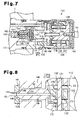
- the tapered surface'124 of the pilot valve 122 is omitted. Instead, a flat surface 122a is formed at the end of the pilot valve 122 facing the pilot valve seat 134.
- the pilot valve 122 is formed of polyimide resin.
- An example of polyimide resin includes VESPEL (registered trademark of DuPont).
- the pilot valve seat 134 includes a projection 134a, the outer diameter of which decreases toward the pilot valve 122.
- the end surface of the projection 134a forms a flat surface 134b, which is arranged to selectively contact the flat surface 122a of the pilot valve 122.
- the pilot valve seat 134 is formed integrally with the main valve body 130 using SUS316L stainless steel.
- Other structures are the same as those of the embodiment shown in Fig. 4. In this case also, the operations and advantages provided are the same as those of the embodiment shown in Fig. 4.
- the sealing effectiveness is maintained while the pressure of the hydrogen gas is in the range of zero to 70 MPa.
- a high pressure valve for hydrogen gas includes a valve seat and a valve member, which is movable to selectively open and close the valve seat.
- One of the valve member and the valve seat is formed of austenitic stainless steel, and the other one of the valve member and the valve seat is formed of flexible synthetic resin or soft metal.
Landscapes
- Engineering & Computer Science (AREA)
- Mechanical Engineering (AREA)
- General Engineering & Computer Science (AREA)
- Fuel Cell (AREA)
- Magnetically Actuated Valves (AREA)
- Filling Or Discharging Of Gas Storage Vessels (AREA)
- Lift Valve (AREA)
- Control Of Fluid Pressure (AREA)
Abstract
Description
Claims (15)
- A high pressure valve for hydrogen gas, the high pressure valve comprising a valve seat and a valve member, which valve member is movable to selectively open and close the valve seat, the high pressure valve characterized by that
one of the valve member and the valve seat is formed of austenitic stainless steel, and the other one of the valve member and the valve seat is formed of flexible synthetic resin or soft metal. - The high pressure valve for hydrogen gas according to claim 1, characterized by that the valve member and the valve seat each has a contact portion, which contact portions contact each other, wherein one of the contact portion of the valve member and the contact portion of the valve seat is formed of austenitic stainless steel, and the other one of the contact portion of the valve member and the contact portion of the valve seat is formed of flexible synthetic resin or soft metal.
- The high pressure valve for hydrogen gas according to claim 1 or 2, characterized by that the synthetic resin is selected from the group consisting of polyimide resin, polyether ether ketone resin, and polyfluoroethylene resin.
- The high pressure valve for hydrogen gas according to claim 3, characterized by that the polyimide resin is VESPEL.
- The high pressure valve for hydrogen gas according to any one of claims 1 to 4, characterized by that the surface roughness of the valve seat and the valve member is less than or equal to 1 µmRa.
- The high pressure valve for hydrogen according to any one of claims 1 to 5, characterized by that the high pressure valve further comprises an accommodating member in which the valve member is located to freely slide in the accommodating member, and
wherein a coating is formed on the surface of the valve member to reduce friction between the valve member and the accommodating member. - The high pressure valve for hydrogen gas according to claim 6, characterized by that the coating is formed through any one of a treatment of physical vapor deposition coating, baking, and plating.
- The high pressure valve for hydrogen gas according to claim 6 or 7, characterized by that the coating is selected from the group consisting of a diamond-like carbon coating, CrN coating, TiN coating, Au coating, MoS2 coating, polytetrafluoroethylene coating, Ni-P plating, and Ni-B plating.
- The high pressure valve for hydrogen gas according to any one of claims 1 to 8, characterized by that the high pressure valve has:wherein the pilot valve body is switched between the open state and the closed state in accordance with excitation and de-excitation of the solenoid, and the main valve body switches from the closed state to the open state when the pilot valve body is switched from the closed state to the open state.a solenoid;a main valve seat and a pilot valve seat;a main valve body, which is switchable between a closed state, where the main valve body contacts the main valve seat, and an open state, where the main valve body is separated from the main valve seat; anda pilot valve body, which is switchable between a closed state, where the pilot valve body contacts the pilot valve seat, and an open state, where the pilot valve body is separated from the pilot valve seat,
- The high pressure valve according to claim 9, characterized by that the high pressure valve further comprises a plunger, which operates in accordance with excitation and de-excitation of the solenoid, wherein the plunger is coupled to the pilot valve body and the main valve body, the main valve body includes a pilot bore and the pilot valve seat, the pilot valve seat includes a pilot valve hole, which is connected to the pilot bore, at least one of the pilot valve body and the main valve body is supported with respect to the plunger to have play in the operational direction of the plunger, when the pilot valve body contacts the pilot valve seat, the pilot valve hole and the pilot bore are closed.
- The high pressure valve according to claim 10, characterized by that the pilot valve body includes a distal end having an outer diameter that decreases toward the pilot valve seat, and the pilot valve hole of the pilot valve seat includes an inner diameter that is set in accordance with the outer diameter of the distal end of the pilot valve body.
- The high pressure valve according to claim 10, characterized by that the pilot valve seat includes a projection having a distal end surface, the pilot valve hole opens at the distal end surface of the projection, and the pilot valve body includes a flat surface, which selectively contacts the distal end surface of the projection, and when the flat surface contacts the distal end surface of the projection, the pilot valve hole is closed.
- The high pressure valve according to any one of claims 1 to 8, characterized by that the high pressure valve is a pressure reducing valve used to reduce the pressure in a tank containing hydrogen gas, the pressure reducing valve comprising:a valve body and a diaphragm, wherein the valve body and the diaphragm define a pressure reducing chamber, the pressure reducing chamber including a valve hole provided with a valve seat; anda valve member located to selectively contact the valve seat, wherein the valve member is connected to the diaphragm, and the diaphragm is displaced in accordance with the pressure in the pressure reducing chamber, and the valve member selectively opens and closes the valve hole in accordance with the displacement of the diaphragm.
- The pressure reducing valve according to claim 13, characterized by that the pressure reducing valve further comprises:an accommodating member, which includes the valve hole and accommodates the valve member, wherein a sealless portion is set between the accommodating member and the valve member.
- A decompression device for connection to a high pressure hydrogen tank, the decompression device comprising the high pressure valve according to claim 9, which is connectable to the high pressure hydrogen tank and the pressure reducing valve according to claim 13, which is connected to the high pressure valve, wherein the decompression device emits decompressed hydrogen gas to the exterior via the high pressure valve and the pressure reducing valve.
Applications Claiming Priority (2)
| Application Number | Priority Date | Filing Date | Title |
|---|---|---|---|
| JP2003188589 | 2003-06-30 | ||
| JP2003188589A JP4330943B2 (en) | 2003-06-30 | 2003-06-30 | High pressure valve for hydrogen gas and decompression device for hydrogen gas |
Publications (3)
| Publication Number | Publication Date |
|---|---|
| EP1493962A2 true EP1493962A2 (en) | 2005-01-05 |
| EP1493962A3 EP1493962A3 (en) | 2005-04-27 |
| EP1493962B1 EP1493962B1 (en) | 2006-08-02 |
Family
ID=33432288
Family Applications (1)
| Application Number | Title | Priority Date | Filing Date |
|---|---|---|---|
| EP20040015220 Expired - Lifetime EP1493962B1 (en) | 2003-06-30 | 2004-06-29 | High pressure valve for hydrogen gas and decompression device for hydrogen gas |
Country Status (4)
| Country | Link |
|---|---|
| US (2) | US20040261866A1 (en) |
| EP (1) | EP1493962B1 (en) |
| JP (1) | JP4330943B2 (en) |
| DE (1) | DE602004001720T2 (en) |
Cited By (3)
| Publication number | Priority date | Publication date | Assignee | Title |
|---|---|---|---|---|
| WO2012003953A1 (en) * | 2010-07-08 | 2012-01-12 | Magna Steyr Fahrzeugtechnik Ag & Co Kg | Electromagnetic valve for a pressure container |
| DE102017101633A1 (en) * | 2017-01-27 | 2018-08-02 | Agilent Technologies, Inc. - A Delaware Corporation - | Rotor device for fluid valve with axially offset fluid structure |
| EP3708888A1 (en) * | 2019-03-14 | 2020-09-16 | Jtekt Corporation | Valve device |
Families Citing this family (49)
| Publication number | Priority date | Publication date | Assignee | Title |
|---|---|---|---|---|
| JP2006177543A (en) * | 2004-11-29 | 2006-07-06 | Jtekt Corp | Valve equipment for high pressure gas |
| US7195035B2 (en) * | 2005-03-01 | 2007-03-27 | Gm Global Technology Operations, Inc. | In-tank hydrogen distribution valve |
| JP2006250239A (en) | 2005-03-10 | 2006-09-21 | Kawasaki Precision Machinery Ltd | Seat block and valve device |
| DE102006026338B4 (en) * | 2005-06-02 | 2013-05-29 | Hochdruck-Reduziertechnik Gmbh | Pressure reducing valve, mobile power supply unit as well as supplied electrical equipment |
| JP5034186B2 (en) * | 2005-08-09 | 2012-09-26 | トヨタ自動車株式会社 | Fuel cell system, gas leak detection device, and gas leak detection method |
| JP4663447B2 (en) * | 2005-08-17 | 2011-04-06 | 豊興工業株式会社 | Valve device |
| JP4911947B2 (en) * | 2005-10-19 | 2012-04-04 | 愛三工業株式会社 | VALVE DEVICE, CONNECTION DEVICE, AND GAS STORAGE DEVICE PROVIDED WITH THE SAME |
| JP5017849B2 (en) * | 2005-11-29 | 2012-09-05 | トヨタ自動車株式会社 | FUEL CELL SYSTEM, FUEL CELL VALVE SYSTEM, AND FUEL GAS SUPPLY DEVICE |
| JP2009030669A (en) * | 2007-07-25 | 2009-02-12 | Tokyo Institute Of Technology | Pulse valve device for supercritical fluid jet injection |
| JP5062680B2 (en) * | 2007-12-11 | 2012-10-31 | 有限会社シノハラ | Valve device |
| EP2233806A1 (en) * | 2007-12-19 | 2010-09-29 | Toyooki Kogyo Co., Ltd. | Solenoid pilot open/close valve |
| KR100871170B1 (en) * | 2008-02-28 | 2008-12-05 | 김상욱 | Automatic Pressure Reducing Valve |
| JP5077688B2 (en) | 2008-05-19 | 2012-11-21 | 株式会社ジェイテクト | Fluid supply valve assembly device |
| JP4740292B2 (en) * | 2008-07-18 | 2011-08-03 | 川崎重工業株式会社 | Seat block and valve device |
| US8251373B2 (en) * | 2009-07-17 | 2012-08-28 | GM Global Technology Operations LLC | Seal performance for hydrogen storage and supply systems |
| MY165246A (en) * | 2009-07-30 | 2018-03-14 | Twister Bv | Tapered throttling valve |
| DE102009028504C5 (en) * | 2009-08-13 | 2014-10-30 | Federal-Mogul Burscheid Gmbh | Piston ring with a coating |
| JP5421059B2 (en) * | 2009-10-21 | 2014-02-19 | 豊興工業株式会社 | solenoid valve |
| JP5153898B2 (en) * | 2010-04-28 | 2013-02-27 | セントラル硝子株式会社 | Valve for filling container of halogen gas or halogen compound gas |
| CN102278490A (en) * | 2010-06-10 | 2011-12-14 | 沃泰阀门(昆山)有限公司 | Faucet valve provided with special sealing surface |
| JP5498269B2 (en) * | 2010-06-15 | 2014-05-21 | 川崎重工業株式会社 | Solenoid open / close valve |
| JP2012207743A (en) * | 2011-03-30 | 2012-10-25 | Honda Motor Co Ltd | Switching valve for high-pressure gas |
| CN102454652B (en) * | 2011-11-18 | 2014-05-07 | 广西柳工机械股份有限公司 | Adjustable hydraulic pilot opening mechanism |
| JP5438745B2 (en) * | 2011-11-28 | 2014-03-12 | 本田技研工業株式会社 | Fluid supply system |
| FR2988157B1 (en) | 2012-03-14 | 2014-04-11 | Air Liquide | TAP FOR STORAGE CONTAINER, CONTAINER HAVING SUCH FAUCET AND USE THEREOF |
| JP5973247B2 (en) * | 2012-06-15 | 2016-08-23 | 株式会社キッツエスシーティー | High pressure check valve and hydrogen station using the same |
| DE102012210424A1 (en) * | 2012-06-20 | 2013-12-24 | Robert Bosch Gmbh | Injector |
| JP5728557B2 (en) * | 2013-10-23 | 2015-06-03 | 本田技研工業株式会社 | Pilot valve for high-pressure hydrogen gas |
| CN104132236A (en) * | 2014-07-31 | 2014-11-05 | 多立恒(北京)能源技术有限公司 | Liquefied gas inflation gun |
| DE102014018391B4 (en) | 2014-12-11 | 2024-02-01 | Cellcentric Gmbh & Co. Kg | Sealing device |
| JP6463647B2 (en) * | 2015-02-26 | 2019-02-06 | 川崎重工業株式会社 | Valve device |
| DE102015005977A1 (en) * | 2015-05-08 | 2016-11-10 | Daimler Ag | extraction valve |
| KR101926914B1 (en) | 2016-07-22 | 2018-12-07 | 현대자동차주식회사 | Fuel supplying valve for fuel cell system |
| EP4166830B1 (en) * | 2017-02-23 | 2024-07-17 | Allfi Ag | Sealing system of a device for passing a medium, in particular in the high-pressure area |
| DE102017211788A1 (en) * | 2017-07-10 | 2019-01-10 | Bayerische Motoren Werke Aktiengesellschaft | Fuel delivery system with a combined safety and access device |
| CN109751417B (en) * | 2017-11-01 | 2020-03-06 | 浙江三花制冷集团有限公司 | Pilot-operated type electromagnetic valve |
| US10253887B1 (en) * | 2018-01-05 | 2019-04-09 | Circor International, Inc. | Stem assembly for a valve |
| US10344757B1 (en) * | 2018-01-19 | 2019-07-09 | Kennametal Inc. | Valve seats and valve assemblies for fluid end applications |
| JP7084198B2 (en) * | 2018-04-20 | 2022-06-14 | 株式会社ジェイテクト | Valve device |
| DE102018113748B3 (en) * | 2018-06-08 | 2019-07-11 | Leinemann Gmbh & Co. Kg | Tank valve and tank with such a valve |
| DE102018215380A1 (en) * | 2018-09-11 | 2020-03-12 | Robert Bosch Gmbh | Valve device for a gaseous medium and tank device for storing a gaseous medium |
| DE102020206678A1 (en) * | 2020-05-28 | 2021-12-02 | Robert Bosch Gesellschaft mit beschränkter Haftung | Shut-off valve for a pressurized gas tank, pressurized gas tank |
| CN111810702B (en) * | 2020-06-29 | 2025-04-18 | 武汉易知鸟科技有限公司 | A pilot valve assembly |
| CN111828652A (en) * | 2020-08-13 | 2020-10-27 | 浙江易达汽车零部件有限公司 | Electromagnetic valve with throttling function |
| CN112113023B (en) * | 2020-09-30 | 2022-07-12 | 泰安福星汽车配件有限公司 | High-efficiency gas pressure reducing device |
| DE102020214161A1 (en) * | 2020-11-11 | 2022-05-12 | Robert Bosch Gesellschaft mit beschränkter Haftung | Tank device for storing a gaseous medium for a fuel cell system |
| US11897438B2 (en) * | 2021-09-17 | 2024-02-13 | Cummins Inc. | Fuel cell vehicle to refuel another vehicle |
| JP7740355B2 (en) * | 2021-11-09 | 2025-09-17 | 株式会社ジェイテクト | Valve Assembly |
| WO2023176734A1 (en) * | 2022-03-15 | 2023-09-21 | 川崎重工業株式会社 | Hydrogen gas valve device and hydrogen gas valve body equipped therewith |
Family Cites Families (46)
| Publication number | Priority date | Publication date | Assignee | Title |
|---|---|---|---|---|
| US2575272A (en) * | 1947-07-17 | 1951-11-13 | Skinner Chuck Company | Rapid closure valve for high-flow rates at low-pressure drop |
| US2716421A (en) * | 1950-12-01 | 1955-08-30 | Hydropress Inc | Valve seat retaining and removal means |
| US2794615A (en) * | 1954-07-15 | 1957-06-04 | Dow Chemical Co | High pressure valve |
| US2868497A (en) * | 1954-08-02 | 1959-01-13 | Texsteam Corp | High-pressure valve assembly |
| US3010695A (en) * | 1959-02-13 | 1961-11-28 | George W Banks | High pressure low torque valve with characterized flow control |
| US3108779A (en) * | 1959-11-12 | 1963-10-29 | Acf Ind Inc | Valve having a valve seat of very thin material |
| US3111141A (en) * | 1961-08-25 | 1963-11-19 | Superior Valve & Fittings Co | High pressure valve |
| US3405906A (en) * | 1966-08-04 | 1968-10-15 | Itt | Solenoid pilot operated valve |
| US3575381A (en) * | 1968-08-23 | 1971-04-20 | Dresser Ind | Valve seat construction |
| US3632081A (en) * | 1970-04-10 | 1972-01-04 | Nasa | Solenoid valve including guide for armature and valve member |
| US3812877A (en) * | 1972-08-28 | 1974-05-28 | Tescom Corp | Pressure regulator assembly |
| JPS52121827U (en) * | 1976-03-12 | 1977-09-16 | ||
| US4269391A (en) * | 1977-04-28 | 1981-05-26 | Nippon Petrochemicals Co., Ltd. | Valve sealing device and a valve |
| US4257450A (en) * | 1979-06-01 | 1981-03-24 | Veriflo Corporation | Pressure-reducing regulator valve for high-pressure gases |
| US4304264A (en) * | 1980-06-18 | 1981-12-08 | Target Rock Corporation | Solenoid actuated valve |
| US4732364A (en) * | 1984-12-17 | 1988-03-22 | Ameron Iron Works USA, Inc. | Wear resistant diamond cladding |
| JPS621479A (en) * | 1985-06-25 | 1987-01-07 | Hitachi Constr Mach Co Ltd | Method for coating surface of reinforced plastic |
| US4719940A (en) * | 1986-08-18 | 1988-01-19 | Victor Equipment Company | Adjustable tied-diaphragm gas pressure regulator |
| JPS63105287A (en) * | 1986-10-20 | 1988-05-10 | Tokico Ltd | Valve device for air compressor |
| US4938450A (en) * | 1989-05-31 | 1990-07-03 | Target Rock Corporation | Programmable pressure reducing apparatus for throttling fluids under high pressure |
| US5002253A (en) * | 1989-10-30 | 1991-03-26 | Sterling Hydraulics, Inc. | Solenoid valve |
| US5048790A (en) * | 1990-07-18 | 1991-09-17 | Target Rock Corporation | Self-modulating control valve for high-pressure fluid flow |
| FR2669938B1 (en) * | 1990-12-04 | 1993-03-19 | Robinetterie Mecanique Ste Gle | BLINDING DEVICE COMPRISING A DEFORMABLE METAL JOINT, AND METHOD FOR THE PRODUCTION THEREOF. |
| US5188017A (en) * | 1991-06-18 | 1993-02-23 | The Consumers' Gas Company, Ltd. | Natural gas cylinder fitting and solenoid valve |
| EP0522913B1 (en) * | 1991-06-28 | 1996-12-27 | U.S. Divers Company, Inc. | Regulator with improved high pressure seat |
| US5144973A (en) * | 1991-11-29 | 1992-09-08 | Safety Assurance Corporation | Safety valve for compressed gas cylinders |
| US5452738A (en) * | 1994-02-22 | 1995-09-26 | Amcast Industrial Corporation | Crashworthy solenoid actuated valve for CNG powered vehicle |
| JPH0875029A (en) * | 1994-09-07 | 1996-03-19 | Nichiden Kogyo Kk | Solenoid valve |
| US5633094A (en) * | 1994-10-28 | 1997-05-27 | Hitachi, Ltd. | Valve having facing layers of co-free Ni-base Alloy |
| US5474104A (en) * | 1995-01-17 | 1995-12-12 | Superior Valve Company | Refueling check valve for compressed natural gas powered vehicles |
| DE19530899C2 (en) * | 1995-08-23 | 2003-08-21 | Bosch Gmbh Robert | Solenoid valve, in particular for a slip-controlled, hydraulic brake system for motor vehicles |
| US5890512A (en) * | 1995-11-06 | 1999-04-06 | Itt Corporation | CNG regulator |
| US5762086A (en) * | 1995-12-19 | 1998-06-09 | Veriflo Corporation | Apparatus for delivering process gas for making semiconductors and method of using same |
| JP3217696B2 (en) * | 1996-04-26 | 2001-10-09 | 京セラ株式会社 | Disc valve |
| JP3921717B2 (en) * | 1996-11-25 | 2007-05-30 | トヨタ自動車株式会社 | Fuel supply control device |
| JP3760036B2 (en) * | 1997-04-16 | 2006-03-29 | 株式会社鷺宮製作所 | Solenoid valve and solenoid valve drive device |
| US6302136B1 (en) * | 1997-06-27 | 2001-10-16 | 3M Innovative Properties Company | Steam valve |
| JPH11118046A (en) * | 1997-10-14 | 1999-04-30 | Honda Motor Co Ltd | Sliding member |
| DE19855667A1 (en) * | 1997-12-05 | 1999-08-26 | Denso Corp | Magnetic valve for vehicle braking system |
| CA2312186A1 (en) * | 2000-06-23 | 2001-12-23 | Erick Girouard | Crashproof instant-on tank valve |
| JP4562885B2 (en) * | 2000-09-01 | 2010-10-13 | 愛三工業株式会社 | Bidirectional pilot type electromagnetic flow path on-off valve and bidirectional piping |
| JP2002115798A (en) * | 2000-10-06 | 2002-04-19 | Neriki:Kk | Valve device |
| JP2003049997A (en) * | 2001-08-03 | 2003-02-21 | Neriki:Kk | Valve device for gas cylinder |
| JP2003090499A (en) * | 2001-09-19 | 2003-03-28 | Samtec Kk | High pressure tank device |
| JP2003166700A (en) * | 2001-11-30 | 2003-06-13 | Nippon Sanso Corp | Container valve with decompression function |
| JP3819867B2 (en) * | 2002-05-15 | 2006-09-13 | 日信工業株式会社 | solenoid valve |
-
2003
- 2003-06-30 JP JP2003188589A patent/JP4330943B2/en not_active Expired - Fee Related
-
2004
- 2004-06-29 US US10/878,613 patent/US20040261866A1/en not_active Abandoned
- 2004-06-29 EP EP20040015220 patent/EP1493962B1/en not_active Expired - Lifetime
- 2004-06-29 DE DE200460001720 patent/DE602004001720T2/en not_active Expired - Lifetime
-
2008
- 2008-01-23 US US12/018,536 patent/US7730905B2/en not_active Expired - Fee Related
Cited By (6)
| Publication number | Priority date | Publication date | Assignee | Title |
|---|---|---|---|---|
| WO2012003953A1 (en) * | 2010-07-08 | 2012-01-12 | Magna Steyr Fahrzeugtechnik Ag & Co Kg | Electromagnetic valve for a pressure container |
| CN103097791A (en) * | 2010-07-08 | 2013-05-08 | 马格纳斯泰尔汽车技术两合公司 | Electromagnetic valve for a pressure container |
| CN103097791B (en) * | 2010-07-08 | 2015-04-29 | 马格纳斯泰尔汽车技术两合公司 | Solenoid valves for pressure vessels |
| DE102017101633A1 (en) * | 2017-01-27 | 2018-08-02 | Agilent Technologies, Inc. - A Delaware Corporation - | Rotor device for fluid valve with axially offset fluid structure |
| EP3708888A1 (en) * | 2019-03-14 | 2020-09-16 | Jtekt Corporation | Valve device |
| US11448329B2 (en) | 2019-03-14 | 2022-09-20 | Jtekt Corporation | Valve device |
Also Published As
| Publication number | Publication date |
|---|---|
| DE602004001720D1 (en) | 2006-09-14 |
| EP1493962A3 (en) | 2005-04-27 |
| DE602004001720T2 (en) | 2007-10-18 |
| US20080121288A1 (en) | 2008-05-29 |
| EP1493962B1 (en) | 2006-08-02 |
| US7730905B2 (en) | 2010-06-08 |
| JP4330943B2 (en) | 2009-09-16 |
| US20040261866A1 (en) | 2004-12-30 |
| JP2005023975A (en) | 2005-01-27 |
Similar Documents
| Publication | Publication Date | Title |
|---|---|---|
| EP1493962B1 (en) | High pressure valve for hydrogen gas and decompression device for hydrogen gas | |
| JP5421059B2 (en) | solenoid valve | |
| US20050061372A1 (en) | Pressure regulator assembly | |
| US8556232B2 (en) | Linear solenoid and valve device using the same | |
| US20170089483A1 (en) | Switching valve | |
| EP1452717B1 (en) | Fuel injection valve | |
| EP1801411A1 (en) | Fluid pump and high-pressure fuel feed pump | |
| JP2002180907A (en) | Vehicle fuel gas supply system | |
| CN109695769B (en) | Latching control valve assembly | |
| US20240240726A1 (en) | Diaphragm valve with actuator bearing element | |
| EP3696398A1 (en) | Regulator | |
| NZ231432A (en) | Disc type electromagnetic valve with diaphragm connected to armature directly or indirectly | |
| EP3699719B1 (en) | Pressure reducing valve | |
| JP5561864B2 (en) | Pressure reducing device for fuel cell system and bellows used therefor | |
| JP5292231B2 (en) | Control valve | |
| US12104704B2 (en) | Three-way valve | |
| JP2009299674A (en) | Control valve unit and connector | |
| JPH07180782A (en) | Solenoid valve | |
| JP2002182751A (en) | Gas pressure reducing valve | |
| US20260002595A1 (en) | Valve diaphragm comprising a spring element, and diaphragm valve | |
| EP4060178A1 (en) | Pressure regulator | |
| EP4614041A1 (en) | Valve for a cooling system | |
| JP2002181208A (en) | Gas pressure reducing valve | |
| WO2025253535A1 (en) | Pressure reduction valve | |
| JP2002182752A (en) | Gas pressure reducing valve |
Legal Events
| Date | Code | Title | Description |
|---|---|---|---|
| PUAI | Public reference made under article 153(3) epc to a published international application that has entered the european phase |
Free format text: ORIGINAL CODE: 0009012 |
|
| AK | Designated contracting states |
Kind code of ref document: A2 Designated state(s): AT BE BG CH CY CZ DE DK EE ES FI FR GB GR HU IE IT LI LU MC NL PL PT RO SE SI SK TR |
|
| AX | Request for extension of the european patent |
Extension state: AL HR LT LV MK |
|
| PUAL | Search report despatched |
Free format text: ORIGINAL CODE: 0009013 |
|
| AK | Designated contracting states |
Kind code of ref document: A3 Designated state(s): AT BE BG CH CY CZ DE DK EE ES FI FR GB GR HU IE IT LI LU MC NL PL PT RO SE SI SK TR |
|
| AX | Request for extension of the european patent |
Extension state: AL HR LT LV MK |
|
| GRAP | Despatch of communication of intention to grant a patent |
Free format text: ORIGINAL CODE: EPIDOSNIGR1 |
|
| 17P | Request for examination filed |
Effective date: 20050920 |
|
| AKX | Designation fees paid |
Designated state(s): DE FR GB |
|
| GRAS | Grant fee paid |
Free format text: ORIGINAL CODE: EPIDOSNIGR3 |
|
| GRAA | (expected) grant |
Free format text: ORIGINAL CODE: 0009210 |
|
| AK | Designated contracting states |
Kind code of ref document: B1 Designated state(s): DE FR GB |
|
| REG | Reference to a national code |
Ref country code: GB Ref legal event code: FG4D |
|
| REF | Corresponds to: |
Ref document number: 602004001720 Country of ref document: DE Date of ref document: 20060914 Kind code of ref document: P |
|
| RAP2 | Party data changed (patent owner data changed or rights of a patent transferred) |
Owner name: TOYOOKI KOGYO KABUSHIKI KAISHA Owner name: JTEKT CORPORATION |
|
| RIN2 | Information on inventor provided after grant (corrected) |
Inventor name: SUZUKI, HIROAKIJTEKT CORPORATION Inventor name: SHIMA, TOSHIHIKO JTEKT CORPORATION Inventor name: SHIRAI, SOICHI Inventor name: TAKEUCHI, YOSHIYUKI JTEKT CORPORATION |
|
| ET | Fr: translation filed | ||
| PLBE | No opposition filed within time limit |
Free format text: ORIGINAL CODE: 0009261 |
|
| STAA | Information on the status of an ep patent application or granted ep patent |
Free format text: STATUS: NO OPPOSITION FILED WITHIN TIME LIMIT |
|
| 26N | No opposition filed |
Effective date: 20070503 |
|
| REG | Reference to a national code |
Ref country code: FR Ref legal event code: PLFP Year of fee payment: 13 |
|
| REG | Reference to a national code |
Ref country code: FR Ref legal event code: PLFP Year of fee payment: 14 |
|
| PGFP | Annual fee paid to national office [announced via postgrant information from national office to epo] |
Ref country code: GB Payment date: 20170628 Year of fee payment: 14 |
|
| REG | Reference to a national code |
Ref country code: FR Ref legal event code: PLFP Year of fee payment: 15 |
|
| GBPC | Gb: european patent ceased through non-payment of renewal fee |
Effective date: 20180629 |
|
| PG25 | Lapsed in a contracting state [announced via postgrant information from national office to epo] |
Ref country code: GB Free format text: LAPSE BECAUSE OF NON-PAYMENT OF DUE FEES Effective date: 20180629 |
|
| PGFP | Annual fee paid to national office [announced via postgrant information from national office to epo] |
Ref country code: FR Payment date: 20230510 Year of fee payment: 20 Ref country code: DE Payment date: 20230502 Year of fee payment: 20 |
|
| REG | Reference to a national code |
Ref country code: DE Ref legal event code: R071 Ref document number: 602004001720 Country of ref document: DE |