JP5973247B2 - High pressure check valve and hydrogen station using the same - Google Patents
High pressure check valve and hydrogen station using the same Download PDFInfo
- Publication number
- JP5973247B2 JP5973247B2 JP2012136204A JP2012136204A JP5973247B2 JP 5973247 B2 JP5973247 B2 JP 5973247B2 JP 2012136204 A JP2012136204 A JP 2012136204A JP 2012136204 A JP2012136204 A JP 2012136204A JP 5973247 B2 JP5973247 B2 JP 5973247B2
- Authority
- JP
- Japan
- Prior art keywords
- pressure
- check valve
- seal
- valve body
- obtuse angle
- Prior art date
- Legal status (The legal status is an assumption and is not a legal conclusion. Google has not performed a legal analysis and makes no representation as to the accuracy of the status listed.)
- Active
Links
- 229910052739 hydrogen Inorganic materials 0.000 title claims description 31
- 239000001257 hydrogen Substances 0.000 title claims description 31
- UFHFLCQGNIYNRP-UHFFFAOYSA-N Hydrogen Chemical compound [H][H] UFHFLCQGNIYNRP-UHFFFAOYSA-N 0.000 title claims description 30
- 238000007789 sealing Methods 0.000 claims description 31
- 239000000463 material Substances 0.000 claims description 12
- 239000004696 Poly ether ether ketone Substances 0.000 claims description 11
- 229920002530 polyetherether ketone Polymers 0.000 claims description 11
- 239000004642 Polyimide Substances 0.000 claims description 10
- 229920001721 polyimide Polymers 0.000 claims description 10
- 239000011347 resin Substances 0.000 claims description 8
- 229920005989 resin Polymers 0.000 claims description 8
- 239000012530 fluid Substances 0.000 description 27
- 238000003780 insertion Methods 0.000 description 4
- 230000037431 insertion Effects 0.000 description 4
- 238000007689 inspection Methods 0.000 description 4
- 239000002184 metal Substances 0.000 description 4
- 229910052751 metal Inorganic materials 0.000 description 4
- 229910045601 alloy Inorganic materials 0.000 description 3
- 239000000956 alloy Substances 0.000 description 3
- 230000003628 erosive effect Effects 0.000 description 3
- 230000001747 exhibiting effect Effects 0.000 description 3
- 230000002093 peripheral effect Effects 0.000 description 3
- 230000005489 elastic deformation Effects 0.000 description 2
- OKTJSMMVPCPJKN-UHFFFAOYSA-N Carbon Chemical compound [C] OKTJSMMVPCPJKN-UHFFFAOYSA-N 0.000 description 1
- RYGMFSIKBFXOCR-UHFFFAOYSA-N Copper Chemical compound [Cu] RYGMFSIKBFXOCR-UHFFFAOYSA-N 0.000 description 1
- 229910000881 Cu alloy Inorganic materials 0.000 description 1
- 238000004891 communication Methods 0.000 description 1
- 229910052802 copper Inorganic materials 0.000 description 1
- 239000010949 copper Substances 0.000 description 1
- 238000010586 diagram Methods 0.000 description 1
- 238000006073 displacement reaction Methods 0.000 description 1
- 229920006351 engineering plastic Polymers 0.000 description 1
- -1 for example Polymers 0.000 description 1
- 239000000446 fuel Substances 0.000 description 1
- 229910002804 graphite Inorganic materials 0.000 description 1
- 239000010439 graphite Substances 0.000 description 1
- 150000002431 hydrogen Chemical class 0.000 description 1
- 238000012423 maintenance Methods 0.000 description 1
- 239000007769 metal material Substances 0.000 description 1
- 239000000203 mixture Substances 0.000 description 1
- 239000010935 stainless steel Substances 0.000 description 1
- 229910001220 stainless steel Inorganic materials 0.000 description 1
- XLYOFNOQVPJJNP-UHFFFAOYSA-N water Substances O XLYOFNOQVPJJNP-UHFFFAOYSA-N 0.000 description 1
- 238000003466 welding Methods 0.000 description 1
Images


Classifications
-
- Y—GENERAL TAGGING OF NEW TECHNOLOGICAL DEVELOPMENTS; GENERAL TAGGING OF CROSS-SECTIONAL TECHNOLOGIES SPANNING OVER SEVERAL SECTIONS OF THE IPC; TECHNICAL SUBJECTS COVERED BY FORMER USPC CROSS-REFERENCE ART COLLECTIONS [XRACs] AND DIGESTS
- Y02—TECHNOLOGIES OR APPLICATIONS FOR MITIGATION OR ADAPTATION AGAINST CLIMATE CHANGE
- Y02E—REDUCTION OF GREENHOUSE GAS [GHG] EMISSIONS, RELATED TO ENERGY GENERATION, TRANSMISSION OR DISTRIBUTION
- Y02E60/00—Enabling technologies; Technologies with a potential or indirect contribution to GHG emissions mitigation
- Y02E60/30—Hydrogen technology
- Y02E60/50—Fuel cells
Landscapes
- Check Valves (AREA)
- Fuel Cell (AREA)
Description
本発明は、高圧用逆止め弁に関し、特に、水素等の高圧流体が流れる水素ステーションなどの流路にインラインチャッキとして用いられる高圧用逆止め弁とこれを用いた水素ステーションに関する。 The present invention relates to a high pressure check valve, and more particularly to a high pressure check valve used as an in-line check in a flow path of a hydrogen station or the like through which a high pressure fluid such as hydrogen flows, and a hydrogen station using the high pressure check valve.
近年、自動車用燃料電池の水素ステーションの供給インフラが普及しつつある。この水素ステーションの配管設備には、通常、流量制御用のバルブなどとともにインラインチャッキである逆止め弁が用いられる。この場合、水素ステーションでは、例えば、約99MPaの高圧の水素が流れることもあるため、流量制御用バルブと同様に逆止め弁も高圧流体に耐え得ることが重要である。 In recent years, the infrastructure for supplying hydrogen stations for automobile fuel cells has become widespread. In the hydrogen station piping equipment, a check valve which is an in-line check is usually used together with a valve for controlling the flow rate. In this case, for example, high-pressure hydrogen of about 99 MPa may flow at the hydrogen station, so it is important that the check valve can withstand the high-pressure fluid as well as the flow control valve.
高圧流体用の逆止め弁としては、例えば、特許文献1の高圧チェックバルブが知られている。このチェックバルブはバルブボデーのほぼ中央にポペットバルブがスプリングを介装された状態で左右に移動可能に嵌入され、その両端に中心水孔を有する中間子が嵌合された構造になっている。ポペットバルブは、バルブボデーの中心孔にガイドされながらこのバルブボデー内を往復動し、弁開時には、流体がポペットバルブの外周に形成された縦溝を介して流れ、弁閉時には、ポペットバルブと中間子との端部同士が平面接触して弁閉状態になる。
一方、特許文献2の逆止弁では、スプリングにより弁閉方向に弁体が弾発され、この弁体の先端側がテーパ状に形成され、この先端に装着されたOリングがテーパ状の弁座に着座することで弁閉状態を維持しようとする構造になっている。
更に、特許文献3の逆止弁では、弁体のOリングと密着可能な屈曲部が弁座に形成され、この屈曲部を起点として第1傾斜部及び第2傾斜部が形成されている。弁閉時には、この弁座側にOリングを装着した弁体が着座して高圧流体を密封シールしてシール部材の寿命を延ばそうとしている。
As a check valve for high pressure fluid, for example, a high pressure check valve of
On the other hand, in the check valve of
Further, in the check valve of
しかしながら、特許文献1のチェックバルブは、ポペットバルブと中間子との端部同士が平面接触によりシールするため、これらの端部が金属面である場合には高圧時に平面同士の間に隙間が生じて漏れが発生するおそれがある。更に、このチェックバルブは、圧力範囲が比較的高圧の場合に限られており、低圧流体が流れた場合に平面接触部分に隙間が生じて漏れを生じる可能性もある。
However, since the check valve of
特許文献2、3のように弁座シールにOリング等のゴム材料を使用した逆止め弁では、超高圧用チェックバルブとして水素ステーション等に使用したときに、高差圧の流速によるエロージョンによって耐久性が悪くなる。このエロージョン対策として、逆止め弁をメタルシールの弁座構造にすることが考えられるが、5MPa程度の低圧時のシール性能が悪くなり、その結果、低圧から超高圧までの幅広い圧力の流体に対して逆止め性能を発揮することが難しくなる。しかも、ゴムシールの場合、繰り返しの開閉動作による耐久性も悪くなり、数千回程度の少ない弁体開閉動作によりシール性が悪化して漏れを生じることがあった。耐久性を向上するためにステンレス製の弁体に別材料を溶着して硬度を上げることも考えられるが、この場合、溶接部に水素脆性の問題があらたに生じるために実施は難しい。弁体全体を高硬度材料で成形することも考えられるが、この場合には高価になるという問題が生じる。
In non-return valves that use rubber materials such as O-rings for valve seat seals as in
本発明は、上記の課題点を解決するために開発したものであり、その目的とするところは、高圧流体が流れる流路に好適な高圧用逆止め弁であり、低圧から超高圧までの流体に対して優れた逆止め性能を発揮しつつ、弁開時には大流量を確保してバルブ容量を向上し、耐久性を飛躍的に向上してシール性を確保しながら弁体の動作回数の限界を延ばすことができ、特に、高圧の水素などの適用流体に好適なインラインチャッキとして用いることが可能な高圧用逆止め弁とこれを用いた水素ステーションを提供することにある。 The present invention has been developed in order to solve the above-mentioned problems, and the object of the present invention is a high pressure check valve suitable for a flow path through which a high pressure fluid flows. While exhibiting excellent non-returning performance, a large flow rate is secured when the valve is opened, the valve capacity is improved, and the limit of the number of operations of the valve body is achieved while dramatically improving durability and ensuring sealing performance. In particular, it is to provide a high-pressure check valve that can be used as an in-line check suitable for an application fluid such as high-pressure hydrogen and a hydrogen station using the same.
上記目的を達成するため、請求項1に係る発明は、管接合部と円筒空間部を有するボデーと管接合部と弁座シール面を有するキャップ体を螺着結合し、円筒空間部内に先端に平面部を有するポペット弁体をスプリングを介して装着することにより弁座シール面に平面部を当接すると共に、弁座シール面には、鈍角でエッジ形状に形成した鈍角エッジ部を設け、この鈍角エッジ部の硬度より平面部の硬度を低い材料で形成し、低圧時のとき、鈍角エッジ部と平面部とのシール幅が狭く、高圧時のとき、平面部が変形して鈍角エッジ部と平面部とのシール幅が広くなるようにしたこと高圧用逆止め弁である。
In order to achieve the above object, the invention according to
請求項2に係る発明は、キャップ体は、流路と先端側の弁座シール面に鈍角エッジ部を有するスリーブと、管接合部を有するキャップとからなる高圧用逆止め弁である。
The invention according to
請求項3に係る発明は、ポペット弁体は、平面部の軸方向に連続する円筒部と、当該ポペット弁体の外周と円筒部とを連通する流路穴を有し、この流路穴の外周側開口部をポペット弁体外周の傾斜面に設けた高圧用逆止め弁である。
The invention according to
請求項4に係る発明は、鈍角エッジ部は、160〜178度程度の鈍角である高圧用逆止め弁である。
The invention according to
請求項5に係る発明は、ポペット弁体の材質は樹脂であり、鈍角エッジ部を有する前記スリーブより硬度が低い材質で形成した高圧用逆止め弁である。
The invention according to
請求項6に係る発明は、ポペット弁体をポリエーテルエーテルケトン(PEEK)又はポリイミド(PI)により形成した高圧用逆止め弁である。 The invention according to claim 6 is a high pressure check valve in which the poppet valve body is formed of polyetheretherketone (PEEK) or polyimide (PI).
請求項7に係る発明は、高圧水素の供給ラインに高圧用逆止め弁を用いた水素ステーションである。
The invention according to claim 7 is a hydrogen station using a high pressure check valve in a high pressure hydrogen supply line.
請求項1に係る発明によると、高圧流体が流れる流路に好適な高圧用逆止め弁であり、弁座シール面に鈍角でエッジ形状の鈍角エッジ部を設け、この弁座シール面に硬度の低いポペット弁体の平面部を当接させるようにし、低圧時のとき、鈍角エッジ部と平面部とのシール幅が狭く、一方、高圧時のとき、平面部が変形して鈍角エッジ部と平面部とのシール幅が広くなるようにしているので、低圧から超高圧までの流体の漏れを確実に防いで優れた逆止め性能を発揮しつつ、弁開時には大流量を確保してバルブ容量を向上し、しかも耐久性を飛躍的に向上してシール性を確保しながら弁体の動作回数の限界を延ばすことができ、特に、高圧の水素などの適用流体に好適なインラインチャッキとして用いることができる。
According to the first aspect of the present invention, the high-pressure check valve is suitable for a flow path through which a high-pressure fluid flows, and the valve seat seal surface is provided with an obtuse and edge-shaped obtuse edge portion, and the valve seat seal surface has hardness. The flat part of the low poppet valve body is brought into contact, and when the pressure is low, the seal width between the obtuse angle edge part and the flat part is narrow. On the other hand, when the pressure is high, the flat part deforms and the obtuse angle edge part and the flat part are flat. than the sealing width of the part is made to be wider, while excellent check performance prevent reliably the leakage of fluid from the low pressure to super-high pressure, the valve capacity when the valve opens to ensure a high flow rate In addition, it is possible to extend the limit of the number of operations of the valve body while ensuring the sealing performance by dramatically improving the durability, and in particular, it should be used as an in-line check suitable for applicable fluids such as high-pressure hydrogen. Can do.
請求項2に係る発明によると、キャップでスリーブの段部面を押圧してガスケットを押圧シールすることにより、スリーブとボデーとの間をガスケットで確実にシールして外部への漏れを防ぐことができ、このときスリーブをボデーに対して回転させることなくシール方向に押圧できる構造としていることで、ガスケットの捩れを防いで高シール性を発揮すると共に、このガスケットの消耗を最小限に抑えることができる。
According to the invention of
請求項3に係る発明によると、弁開時に流路穴に流れ込む流体を、傾斜面で案内することにより、大流量を確保することが可能になる。
According to the invention which concerns on
請求項4に係る発明によると、鈍角エッジ部を160〜178度程度の鈍角に設けることで、5〜10MPa程度の低圧では、鈍角エッジ部により平面部とのシール性を確保しながらこの鈍角エッジ部を中心とした狭いシール幅を形成して漏れを確実に防ぐことができる。一方、99MPa程度の超高圧では、平面部が弁座シール面に沿うように変形することで鈍角エッジ部を中心とした広いシール幅によって高圧流体の漏れを確実に防止し、しかも高シール性を長期間維持でき、繰り返し開閉動作した場合の耐久性にも優れている。
According to the invention according to
請求項5に係る発明によると、ポペット弁体を樹脂によってスリーブよりも低い硬度に設けることで、弁閉シール時にポペット弁体をスリーブに対して確実に変形させることができ、例えば、ポペット弁体をロックウェル硬度M99以上の樹脂で形成した場合、5〜10MPa程度の低い圧力ではシール幅を狭くしながらシール性を確保し、99MPaの超高圧ではポペット弁体がより弾性変形してシール幅を広くすることでシール性を向上できる。
According to the invention which concerns on
請求項6に係る発明によると、ポペット弁体をポリエーテルエーテルケトン(PEEK)又はポリイミド(PI)により形成することで、99MPa程度の高圧にも耐え得る強度を発揮し、繰り返し逆止め動作をおこなった場合にもその弾性により優れたシール性と耐久性とを維持できる。 According to the sixth aspect of the present invention, the poppet valve body is formed of polyether ether ketone (PEEK) or polyimide (PI), thereby exhibiting strength that can withstand a high pressure of about 99 MPa and repeatedly performing a non-return operation. Even in the case of high resistance, excellent elasticity and durability can be maintained due to its elasticity.
請求項7に係る発明によると、高圧用逆止め弁がインラインチャッキとして機能して、低圧から超高圧までの流体の漏れを防いで優れた逆止め性能を発揮しつつ、弁開時には大流量を確保してバルブ容量を向上し、しかも耐久性を飛躍的に向上してシール性を確保しながらこの高圧用逆止め弁の弁体の動作回数の限界を延ばすことにより、メンテナンスの頻度を低減することができる水素ステーションを提供できる。
According to the seventh aspect of the invention, the high pressure check valve functions as an inline check, prevents leakage of fluid from low pressure to ultra high pressure, and exhibits excellent check performance, while providing a large flow rate when the valve is opened. The maintenance frequency is reduced by extending the limit of the number of operation of the valve body of this high pressure check valve while ensuring the seal capacity by dramatically improving the durability by ensuring the valve capacity. A hydrogen station can be provided.
以下に、本発明における高圧用逆止め弁の実施形態を図面に基づいて詳細に説明する。図1においては、本発明の高圧用逆止め弁の実施形態を示しており、図2においてはスリーブ、図4にポペット弁体を示している。
図1に示すように、本発明における逆止め弁は、ボデー1、キャップ体2、ポペット弁体3、ガスケット4、スプリング5を有している。
Embodiments of a high pressure check valve according to the present invention will be described below in detail with reference to the drawings. FIG. 1 shows an embodiment of a high pressure check valve according to the present invention, FIG. 2 shows a sleeve, and FIG. 4 shows a poppet valve body.
As shown in FIG. 1, the check valve in the present invention includes a
図1において、ボデー1は、例えば、ステンレス合金(SUS316)によって略筒状に形成されている。ボデー1の一端側、図において右側には雌螺子10からなる管接合部が形成され、この管接合部10には図示しない外部継手の雄螺子を螺合可能になっている。この管接合部10に続けて縮径穴11が形成され、この縮径穴11と連通して縮径穴11よりも拡径した円筒空間部12が設けられている。更に、円筒空間部12に続いて雌ねじ部13が形成されている。
In FIG. 1, the
図3に示すように、ボデー1の円筒空間部12よりも開口側には開口側端面14が形成され、この開口側端面14にはガスケット4を装着可能になっている。開口側端面14には鈍角のエッジシール部15が形成され、このエッジシール部15の角度α1は、160〜178度程度からなり、本実施形態では、この角度α1を170度の鈍角としている。このエッジシール部15により、ガスケット4をシール可能となる。ボデー1における管接合部10と縮径穴11との間には、気密検査用の検査孔26が設けられている。
As shown in FIG. 3, an opening-
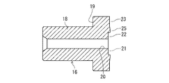
図1に示すように、キャップ体2は、スリーブ16と、キャップ17とからなっている。図2に示したスリーブ16は、金属材料により形成され、本実施形態ではステンレス合金(SUS316)により設けられている。このスリーブ16は、筒部18とこの筒部18よりも拡径した段部面19とを有し、内部にはボデー1の円筒空間部12と連通する流路20が設けられている。図3において、スリーブ16のポペット弁体3との対向面である先端側には弁座シール面21が形成され、この弁座シール面21には、鈍角でエッジ形状の鈍角エッジ部22が形成されている。
As shown in FIG. 1, the
鈍角エッジ部22は断面が山状であり、この山の角度θは、160〜178度程度に設けられ、本実施形態ではこの鈍角エッジ部22の内径側と外径側とのテーパ角が異なっている。図3において、内径側テーパ角θ1は5°、外径側テーパ角θ2は2°に形成されており、これらのテーパ角θ1、θ2により鈍角エッジ部22の角度θは173°の鈍角に設けられている。外径側テーパ角θ2を内径側テーパ角θ1よりも小さく形成しているのは、低圧時のときには、後述するシール径(シールエッジ径Ds)を小さくし、高圧時のときには、ポペット弁体3の後述する平面部35とのシール幅を外径方向に広くするためである。これにより、低圧時から高圧時まで、確実にシールすることが可能になる。鈍角エッジ部22の頂点付近22aは、鋭くする必要はなく、半径の小さい断面R形状としてもよい。なお、外径側テーパ角θ2を0°より大きく設定し、例えば、1°であってもよく、本実施形態においては、0°<θ2<5°、より好ましくは、1°<θ2<3°の範囲に設定するのがよい。また、前述のように、内径側テーパ角θ1を外径側テーパ角θ2よりも大きく形成しているので、高圧時のときに、弁座シール面21の内周縁部(流路20との交点)がポペット弁体3の平面部35を押圧するのを防ぎ、平面部35の損傷なく、確実な面シールを行うことができる。
The obtuse
スリーブ16の弁座シール面21よりも外径側において、ボデー1の開口側端面14との対向位置である先端面23には、鈍角のエッジシール部25が形成されている。このエッジシール部25の角度α2は、例えば、ボデー1と同様に160〜178°程度になっている。本実施形態では、この角度α2は、角度α1と同じ170°の鈍角に設けられている。
On the outer diameter side of the valve
図1に示したキャップ17は、例えば、ボデー1と同じステンレス合金からなり、このキャップ2の内部には挿入穴部30が形成され、この挿入穴部30に続けて雌螺子部からなる管接合部31が形成されている。管接合部31には、ボデー1の雌螺子10と同様に、図示しない外部継手の雄螺子部を螺合可能になっている。キャップ17のボデー取付け側には雌ねじ部13に螺合可能な雄ねじ部32が形成され、この雄ねじ部32を介してキャップ17がボデー1に螺合により取付けられる。キャップ17のスリーブ16側には、このスリーブ押圧用の端部面33が形成されている。キャップ17における管接合部31と挿入穴部30との間には、気密検査用の検査孔27が設けられている。
The
キャップ体2をボデー1に取付けるときには、スリーブ16の段部面19をキャップ17の端部面33で押圧するように、キャップ17をボデー1にガスケット4を介して螺着結合する。スリーブ16は、筒部18が挿入穴部30に挿入されるようにキャップ17に取付けられ、このスリーブ16とボデー1との間に外部シール部34が設けられる。外部シール部34は、前記したボデー1側のエッジシール部15、スリーブ16側のエッジシール部25の両者により、金属製のガスケット4を挟圧シールすることにより構成される。
When the
ガスケット4は、例えば、銅又は銅合金などにより形成され、ボデー1の雌ねじ部13と、スリーブ16の雄ねじ部32との螺着により、エッジシール部15、25の間に挟着されている。このガスケット4によって、ボデー1とスリーブ16との間の漏れが防がれる。
The
図4に示したポペット弁体3は、先端に平面部35を有しており、この平面部35の軸方向に連続する円筒部37と、当該ポペット弁体3の外周38と円筒部37とを連通する流路穴36を有している。この連通路である流路穴36は、平面部35と円筒部37との間のポペット弁体3の外周側に径方向90°毎に4つ配置され、弁開時にはこの流路穴36を介して縮径穴11と流路20とが連通可能になる。流路穴36における外周側開口部39は、ポペット弁体3の外周38に設けた傾斜面40に設けられている。平面部35の外径D3と円筒部37の外径D4とは、外径D3<外径D4の関係に設定されている。本実施形態の傾斜面40の谷部は、平面部35の外径D3よりも小径に設定されている。これにより、ポペット弁体3の外周には、傾斜面40付近に凹部が形成され、流体が効率的に案内されている。ポペット弁体3は、ボデー1の円筒空間部12にコイルスプリングからなるスプリング5を介して装着され、スプリング5の弾発力によりスリーブ16の弁座シール面21に平面部35を当接可能になっている。
The
ポペット弁体3は、平面部35が鈍角エッジ部22の硬度よりも低くなるように、比較的硬度の低い材料で形成されている。本実施形態では、ポペット弁体3の材質は樹脂であり、この樹脂は、鈍角エッジ部22を有するスリーブ16の硬度よりも低い材質で且つ、高圧流体の封止に必要な高強度を有する材質になっている。この樹脂としては、例えば、スーパーエンジニアリングプラスチックに属するポリエーテルエーテルケトン(PEEK)又はポリイミド(PI)であり、本実施形態では、PEEKに30%のグラファイトを混合したものを用いてポペット弁体を形成した。なお、本実施形態において、「平面部35が鈍角エッジ部22の硬度より低い」とは、流体圧の上昇に伴って、平面部35と鈍角エッジ部22の弁座シール面21とのシール幅が広がる一方、流体圧の下降に伴って、シール幅が狭くなるよう、平面部35側が弾性変形する程度の硬度の低さをいう。
The
このような低い硬度のポペット弁体3により、低圧時のとき、図6(a)に示すように、鈍角エッジ部22と平面部35とのシール幅W1が狭くなり、高圧時のとき、図6(b)に示すように、平面部35が変形して鈍角エッジ部22と平面部35とのシール幅W2が広くなるようになっている。内周側と連通する4つの流路穴36が等間隔に設けられ、弁開時には、この流路穴36を介して縮径穴11と流路20とが連通可能になる。
With such a low hardness
ポペット弁体3は、ボデー1の円筒空間部12に遊嵌状態で往復動可能にガイドされ、通常時にはスプリング5の弾発力によりスリーブ16の方向に付勢されている。この場合、ポペット弁体3の円筒部分を円柱部分の2倍程度の長さに設けることにより、ポペット弁体3は、傾きが防がれつつ確実にシール状態を維持しながらボデー1内を摺動可能になっている。
ポペット弁体3の4つの流路穴36の穴面積やポペット弁体3が開動作したときのスリーブ16の弁座開口面積(流路20の開口面積)は、ボデー1の縮径穴11の面積よりも大きくなっている。
The
The hole area of the four flow path holes 36 of the
高圧用逆止め弁を組込む際には、ボデー1の円筒空間部12にポペット弁体3をスプリング5により弾発状態で装着し、スリーブ16の筒部18を挿入したキャップ17をボデー1に螺着して一体化する。ボデー1の開口側端面14とスリーブ16の先端面23との間には、前述したようにガスケット4が介在され、ボデー1の雌ねじ部13とスリーブ16の雄ねじ部32との螺着によりこのガスケット4がエッジシール部15、25の間に挟着される。キャップ17をボデー1に螺着する際、スリーブ16は回転することなくガスケット4に当接するため、エッジシール部25が損傷するのを防ぐことができる。
When assembling the high pressure check valve, the
続いて、上述した実施形態の高圧用逆止め弁の動作を説明する。
図5においては、逆止め弁の弁開状態を示している。図において左方から高圧流体が流れると、その流体圧によってポペット弁体3がスプリング5の弾発力に抗して右方向に押圧され、スリーブ16の弁座シール面21が開口した状態になり、矢印に示すように流体が流路20から円筒空間部12に流れ、流路穴36を介してポペット弁体3内部に案内され、このボペット弁体3を介して縮径穴11よりボデー1の外部へと流れる。前述したように、流路穴36の穴面積やスリーブ16の弁座開口面積は、ボデー1の流路面積よりも大きく設けていることで、高Cv値が確保されている。
Subsequently, the operation of the high pressure check valve of the above-described embodiment will be described.
In FIG. 5, the check valve is opened. In the drawing, when a high-pressure fluid flows from the left side, the
図1において、流体が逆流しようとしたときには、ポペット弁体3がその流体圧によって左方向に押され、弁座シール面21に平面部35が押圧される。その際、平面部35が逆止圧力の増加に応じて弾性変形し、接触面積を増加しつつ弁座シール面21に当接シールする。
In FIG. 1, when the fluid tries to flow backward, the
図6において、このときの逆止圧力の大きさの違いによる弁座の当接状態の変化を説明する。
ポペット弁体3に逆止圧力が加わったときには、先ず、平面部35が弁座シール面21の鈍角エッジ部22に接触し、続いてこの平面部35が鈍角である弁座シール面21に沿うように変形して当接する。鈍角エッジ部22がシールするときのシールエッジ径Dsは、小さいほどシールするために必要な荷重が少なくて済むため、できるだけ小さくなるように形成されている。
In FIG. 6, the change of the contact state of the valve seat due to the difference in the magnitude of the check pressure at this time will be described.
When a check pressure is applied to the
このシール時において、低圧時のときには、図6(a)に示すように、弁座シール面21に平面部35がシール幅W1で当接シールする。この場合、ポペット弁体3がスリーブ16側に押される力が弱いため、この鈍角エッジ部22と平面部35とのシール幅W1が狭くなっている。このように狭いシール幅W1によって弁座シール面21と平面部35とがシールされることで高いシール性が発揮される。
At the time of this sealing, when the pressure is low, as shown in FIG. 6A, the
一方、高圧時のときには、図6(b)に示すように、弁座シール面21に平面部35がシール幅W2で当接シールする。この場合、ポペット弁体3がスリーブ16側に押される力が強くなっているため、シール幅W2はシール幅W1に比べて広くなっている。このように広いシール幅W2で弁座シール面21と平面部35とがシールされることで、シール性を高めて高圧流体を確実に逆止めできる。しかも、シール幅が広くなることで平面部35の単位面積当たりに加わる力を小さくできるため、耐久性が良くなることから長期に亘って高シール性を維持できる。
On the other hand, at the time of high pressure, as shown in FIG. 6B, the
このときのポペット弁体3のシールエッジ径Dsを最小寸法にし、鈍角エッジ部22の内径側テーパ角度θ1を5°、外径側テーパ角度θ2を2°に設けていることで、特に、高圧時において外側に向けて広がるようにシール幅W3が形成されつつ平面部35が変形して高いシール性を発揮でき、耐久性もより向上する。例えば、テーパ角度θ1、θ2を調節し、平面部35の弾性変形量が0.03mmとなる隙間Cを鈍角エッジ部22の内径側に設けることでシール幅W2を1.2mm程度とすることができ、このシール幅W2により高圧の逆止圧力に耐え得ることが可能となる。このように、ポペット弁体3の弾性変位内で収まるように弁座シール面21の角度を設定することが望ましい。
At this time, the seal edge diameter Ds of the
上記したように、本発明の高圧用逆止め弁は、ボデー1と、スリーブ16とキャップ17とからなるキャップ体2を、ガスケット4を介して螺着結合し、円筒空間部12内にスプリング5を介してポペット弁体3を装着し、スリーブ16の弁座シール面21にポペット弁体3の平面部35を当接可能に設け、弁座シール面21に鈍角エッジ部22を設け、この鈍角エッジ部22の硬度より平面部35の硬度が低くなるような材料で形成されている。そして、低圧時のとき、鈍角エッジ部22と平面部35とのシール幅W1が狭くなるようになっており、高圧時のとき、平面部35が変形してこの平面部35と鈍角エッジ部22とのシール幅W2が広くなるようにしているので、低圧から高圧までの幅広い圧力の流体に対して、平面部35がその圧力に応じて異なる変形量により変形して必要なシール面圧を発揮する。これにより、例えば、5MPaの低圧流体、又は99MPaの超高圧流体の何れの場合にも逆止性能を確実に発揮し、超高圧用のチェックバルブとして用いた場合にも、高圧時はおろか、低圧時においても確実に逆止め性能を発揮して漏れを防止できる。しかも、少ない部品点数で簡単な組み合わせにより設けることができるため、低コストで製作できる。
As described above, in the high pressure check valve of the present invention, the
更に、ポペット弁体3の材質を、ポリエーテルエーテルケトン(PEEK)又はポリイミド(PI)等の樹脂により形成しているため耐久性を向上でき、繰り返しの弁体開閉動作による消耗を最小限に抑えて限界開閉回数を向上し、長期に亘って高シール性を維持できる。水素ステーション等に使用したときにもエロージョンによる消耗を最小限に抑えることが可能になる。本実施形態の逆止め弁(呼び径9/16インチ)を用い、水素99MPa下における耐久試験を行った。25000回の開閉を行ったが、弁座からの漏れはなく、弁座シール性が確保されていることを確認した。
Furthermore, since the material of the
図3において、ボデー1の円筒空間部12の開口側端面14に鈍角のエッジシール部15を形成し、スリーブ16の先端側に鈍角のエッジシール部25を形成して、この両者のエッジシール部15、25で金属製のガスケット4を挟圧して外部シール部34を構成していることから、弁座シール面21と平面部35とのシールの場合と同様に、これらのエッジシール部15、25によって高いシール面圧を発揮してボデー1とスリーブ16とをシールできる。この場合、スリーブ16の外径を最小限に抑えることも可能となり、例えば、図1のボデー1の円筒空間部12の内径d1をφ14mmとした場合、このボデー1の必要肉厚が21mm程度となり、このときのスリーブ16の流路20の内径d2をφ6.4mm、必要肉厚を7mm程度に抑えながらスリーブ3を小型化しつつ大流量化できる。
In FIG. 3, an obtuse
図7においては、本発明の高圧用逆止め弁を用いた水素ステーションを示したものである。水素ステーションは、例えば、蓄圧器70、圧縮機71、ディスペンサ72、プレクール熱交換器73、迅速継手74、充填ホース75、充填ノズル76、車載タンク77を有し、これらは高圧水素の供給ライン78としてシステムを構成している。
FIG. 7 shows a hydrogen station using the high pressure check valve of the present invention. The hydrogen station has, for example, a
本発明の高圧用逆止め弁であるバルブ本体85は、例えば、インラインチャッキとしてディスペンサ72の二次側に設けられ、或は、その他の供給ラインに設けられる。このバルブ本体85により一次側への水素漏れが防がれて優れた逆止め性能が発揮されると共に、弁開時の大流量を確保し、耐久性やシール性も向上する。 The valve main body 85 which is the high pressure check valve of the present invention is provided on the secondary side of the dispenser 72 as, for example, an inline check, or is provided in another supply line. This valve main body 85 prevents hydrogen leakage to the primary side and exhibits excellent non-return performance, as well as ensuring a large flow rate when the valve is opened and improving durability and sealing performance.
なお、水素ステーションの各ユニットの接続部位には手動弁81が設けられ、各ユニットの一次側又は二次側に適宜に自動弁80が設けられている。
蓄圧器70の内部は、複数のタンクに分かれており、それぞれのタンクと圧縮機71とを接続するバルブ80、及びそれぞれのタンクとディスペンサ72とを接続するバルブ80を適宜切り替えることにより、所定圧に至ったタンクから水素をディスペンサに供給する一方、所定の下限値圧を下回ったタンクには、圧縮機71から水素を前記所定圧に至るまで充填する。この水素ステーションに設けられた供給ライン78において、所定のプログラムによって水素供給が制御され、車両供給量に応じて適宜に水素を供給制御可能になっている。
Note that a
The inside of the
1 ボデー
2 キャップ体
3 ポペット弁体
4 ガスケット
5 スプリング
10 雌螺子(管接合部)
12 円筒空間部
14 開口側端面
15、25 エッジシール部
16 スリーブ
17 キャップ
19 段部面
20 流路
21 弁座シール面
22 鈍角エッジ部
31 雌螺子部(管接合部)
33 端部面
35 平面部
85 バルブ本体
W1、W2 シール幅
1
DESCRIPTION OF
33
Claims (7)
Priority Applications (1)
| Application Number | Priority Date | Filing Date | Title |
|---|---|---|---|
| JP2012136204A JP5973247B2 (en) | 2012-06-15 | 2012-06-15 | High pressure check valve and hydrogen station using the same |
Applications Claiming Priority (1)
| Application Number | Priority Date | Filing Date | Title |
|---|---|---|---|
| JP2012136204A JP5973247B2 (en) | 2012-06-15 | 2012-06-15 | High pressure check valve and hydrogen station using the same |
Related Child Applications (1)
| Application Number | Title | Priority Date | Filing Date |
|---|---|---|---|
| JP2014143805A Division JP5973504B2 (en) | 2014-07-14 | 2014-07-14 | External seal structure of high-pressure piping flow path and hydrogen station |
Publications (3)
| Publication Number | Publication Date |
|---|---|
| JP2014001765A JP2014001765A (en) | 2014-01-09 |
| JP2014001765A5 JP2014001765A5 (en) | 2015-01-29 |
| JP5973247B2 true JP5973247B2 (en) | 2016-08-23 |
Family
ID=50035137
Family Applications (1)
| Application Number | Title | Priority Date | Filing Date |
|---|---|---|---|
| JP2012136204A Active JP5973247B2 (en) | 2012-06-15 | 2012-06-15 | High pressure check valve and hydrogen station using the same |
Country Status (1)
| Country | Link |
|---|---|
| JP (1) | JP5973247B2 (en) |
Families Citing this family (6)
| Publication number | Priority date | Publication date | Assignee | Title |
|---|---|---|---|---|
| JP6379959B2 (en) * | 2014-10-07 | 2018-08-29 | 株式会社デンソー | Refrigeration cycle compressor |
| JP6517040B2 (en) * | 2015-02-24 | 2019-05-22 | 株式会社キッツエスシーティー | High pressure filter device and hydrogen station using the same |
| JP6613035B2 (en) * | 2015-02-24 | 2019-11-27 | 株式会社キッツエスシーティー | High pressure needle valve and hydrogen station using the same |
| JP6654420B2 (en) * | 2015-12-14 | 2020-02-26 | 株式会社キッツ | High pressure check valve and hydrogen station using it |
| WO2018003982A1 (en) * | 2016-06-30 | 2018-01-04 | 株式会社キッツ | Check valve |
| CN113405016B (en) * | 2021-06-30 | 2022-10-14 | 中材科技(成都)有限公司 | High-pressure composite gas cylinder with internal sealing structure |
Family Cites Families (7)
| Publication number | Priority date | Publication date | Assignee | Title |
|---|---|---|---|---|
| JPS59110474U (en) * | 1983-01-18 | 1984-07-25 | 株式会社山武 | valve seat |
| EP0295479B1 (en) * | 1987-06-16 | 1993-11-24 | Gerd Hörmansdörfer | Sealing joint |
| US5433710A (en) * | 1993-03-16 | 1995-07-18 | Minimed, Inc. | Medication infusion pump with fluoropolymer valve seat |
| JP4330943B2 (en) * | 2003-06-30 | 2009-09-16 | 株式会社ジェイテクト | High pressure valve for hydrogen gas and decompression device for hydrogen gas |
| US7357151B2 (en) * | 2003-09-15 | 2008-04-15 | Exxonmobil Upstream Research Company | Fluid control devices |
| JP4976436B2 (en) * | 2009-03-09 | 2012-07-18 | 日立機材株式会社 | Hydraulic damper |
| JP5048814B2 (en) * | 2010-07-20 | 2012-10-17 | 本田技研工業株式会社 | Operation method of hydrogen filling system |
-
2012
- 2012-06-15 JP JP2012136204A patent/JP5973247B2/en active Active
Also Published As
| Publication number | Publication date |
|---|---|
| JP2014001765A (en) | 2014-01-09 |
Similar Documents
| Publication | Publication Date | Title |
|---|---|---|
| JP5973247B2 (en) | High pressure check valve and hydrogen station using the same | |
| JP6003888B2 (en) | High pressure connector | |
| JP5593470B2 (en) | Check valve | |
| US20120168659A1 (en) | Butterfly valve | |
| JP2016205408A (en) | Gasket for fluid coupling and fluid coupling | |
| JP6490007B2 (en) | Trunnion ball valve for high pressure and hydrogen station using the same | |
| JP6654420B2 (en) | High pressure check valve and hydrogen station using it | |
| ITMI20092115A1 (en) | METAL GASKET FOR BALL VALVES AND BALL VALVE INCLUDING SUCH GASKET | |
| CA2953094C (en) | Structure and method for fastening ball seat for ball valve, trunnion-type ball valve, and hydrogen station using said valve | |
| JP5973504B2 (en) | External seal structure of high-pressure piping flow path and hydrogen station | |
| JP6978414B2 (en) | Check valve and hydrogen station | |
| JP2012013141A (en) | Trunnion type ball valve | |
| JP2023077130A (en) | Check valve | |
| JP6865623B2 (en) | Trunnion type ball valve for high pressure and hydrogen station using it | |
| JP4959464B2 (en) | Control valve | |
| CN209818821U (en) | Efficient and leak-proof T-shaped valve | |
| KR101446488B1 (en) | Polyethylene Ball Valves | |
| CN221857631U (en) | Leakage-free high-pressure large-flow check valve | |
| US12000493B2 (en) | Check valve | |
| CN211951515U (en) | Floating valve ball | |
| JP7281175B2 (en) | valve | |
| CN105673861A (en) | Sealing device capable of relieving pressure automatically | |
| KR20210076684A (en) | Metal gasket and valve with this | |
| JP2021134813A (en) | Excess flow prevention valve | |
| JP2018146114A (en) | Adhesion method of ball seat for high-pressure ball valve |
Legal Events
| Date | Code | Title | Description |
|---|---|---|---|
| A521 | Request for written amendment filed |
Free format text: JAPANESE INTERMEDIATE CODE: A523 Effective date: 20141209 |
|
| A621 | Written request for application examination |
Free format text: JAPANESE INTERMEDIATE CODE: A621 Effective date: 20141209 |
|
| A977 | Report on retrieval |
Free format text: JAPANESE INTERMEDIATE CODE: A971007 Effective date: 20151009 |
|
| A131 | Notification of reasons for refusal |
Free format text: JAPANESE INTERMEDIATE CODE: A131 Effective date: 20151027 |
|
| A521 | Request for written amendment filed |
Free format text: JAPANESE INTERMEDIATE CODE: A523 Effective date: 20151222 |
|
| TRDD | Decision of grant or rejection written | ||
| A01 | Written decision to grant a patent or to grant a registration (utility model) |
Free format text: JAPANESE INTERMEDIATE CODE: A01 Effective date: 20160705 |
|
| A61 | First payment of annual fees (during grant procedure) |
Free format text: JAPANESE INTERMEDIATE CODE: A61 Effective date: 20160714 |
|
| R150 | Certificate of patent or registration of utility model |
Ref document number: 5973247 Country of ref document: JP Free format text: JAPANESE INTERMEDIATE CODE: R150 |
|
| R250 | Receipt of annual fees |
Free format text: JAPANESE INTERMEDIATE CODE: R250 |
|
| R250 | Receipt of annual fees |
Free format text: JAPANESE INTERMEDIATE CODE: R250 |
|
| R250 | Receipt of annual fees |
Free format text: JAPANESE INTERMEDIATE CODE: R250 |
|
| R250 | Receipt of annual fees |
Free format text: JAPANESE INTERMEDIATE CODE: R250 |
|
| R250 | Receipt of annual fees |
Free format text: JAPANESE INTERMEDIATE CODE: R250 |
|
| R250 | Receipt of annual fees |
Free format text: JAPANESE INTERMEDIATE CODE: R250 |