EP1493959A2 - Two-axial rotational driving apparatus and driven member rotation control system - Google Patents
Two-axial rotational driving apparatus and driven member rotation control system Download PDFInfo
- Publication number
- EP1493959A2 EP1493959A2 EP04015484A EP04015484A EP1493959A2 EP 1493959 A2 EP1493959 A2 EP 1493959A2 EP 04015484 A EP04015484 A EP 04015484A EP 04015484 A EP04015484 A EP 04015484A EP 1493959 A2 EP1493959 A2 EP 1493959A2
- Authority
- EP
- European Patent Office
- Prior art keywords
- rotation
- axis
- tilt
- rotational driving
- pan
- Prior art date
- Legal status (The legal status is an assumption and is not a legal conclusion. Google has not performed a legal analysis and makes no representation as to the accuracy of the status listed.)
- Granted
Links
Images



Classifications
-
- F—MECHANICAL ENGINEERING; LIGHTING; HEATING; WEAPONS; BLASTING
- F16—ENGINEERING ELEMENTS AND UNITS; GENERAL MEASURES FOR PRODUCING AND MAINTAINING EFFECTIVE FUNCTIONING OF MACHINES OR INSTALLATIONS; THERMAL INSULATION IN GENERAL
- F16M—FRAMES, CASINGS OR BEDS OF ENGINES, MACHINES OR APPARATUS, NOT SPECIFIC TO ENGINES, MACHINES OR APPARATUS PROVIDED FOR ELSEWHERE; STANDS; SUPPORTS
- F16M11/00—Stands or trestles as supports for apparatus or articles placed thereon ; Stands for scientific apparatus such as gravitational force meters
- F16M11/02—Heads
- F16M11/18—Heads with mechanism for moving the apparatus relatively to the stand
-
- F—MECHANICAL ENGINEERING; LIGHTING; HEATING; WEAPONS; BLASTING
- F16—ENGINEERING ELEMENTS AND UNITS; GENERAL MEASURES FOR PRODUCING AND MAINTAINING EFFECTIVE FUNCTIONING OF MACHINES OR INSTALLATIONS; THERMAL INSULATION IN GENERAL
- F16M—FRAMES, CASINGS OR BEDS OF ENGINES, MACHINES OR APPARATUS, NOT SPECIFIC TO ENGINES, MACHINES OR APPARATUS PROVIDED FOR ELSEWHERE; STANDS; SUPPORTS
- F16M11/00—Stands or trestles as supports for apparatus or articles placed thereon ; Stands for scientific apparatus such as gravitational force meters
- F16M11/02—Heads
- F16M11/04—Means for attachment of apparatus; Means allowing adjustment of the apparatus relatively to the stand
- F16M11/06—Means for attachment of apparatus; Means allowing adjustment of the apparatus relatively to the stand allowing pivoting
- F16M11/10—Means for attachment of apparatus; Means allowing adjustment of the apparatus relatively to the stand allowing pivoting around a horizontal axis
-
- F—MECHANICAL ENGINEERING; LIGHTING; HEATING; WEAPONS; BLASTING
- F16—ENGINEERING ELEMENTS AND UNITS; GENERAL MEASURES FOR PRODUCING AND MAINTAINING EFFECTIVE FUNCTIONING OF MACHINES OR INSTALLATIONS; THERMAL INSULATION IN GENERAL
- F16M—FRAMES, CASINGS OR BEDS OF ENGINES, MACHINES OR APPARATUS, NOT SPECIFIC TO ENGINES, MACHINES OR APPARATUS PROVIDED FOR ELSEWHERE; STANDS; SUPPORTS
- F16M11/00—Stands or trestles as supports for apparatus or articles placed thereon ; Stands for scientific apparatus such as gravitational force meters
- F16M11/20—Undercarriages with or without wheels
- F16M11/2007—Undercarriages with or without wheels comprising means allowing pivoting adjustment
- F16M11/2014—Undercarriages with or without wheels comprising means allowing pivoting adjustment around a vertical axis
-
- F—MECHANICAL ENGINEERING; LIGHTING; HEATING; WEAPONS; BLASTING
- F16—ENGINEERING ELEMENTS AND UNITS; GENERAL MEASURES FOR PRODUCING AND MAINTAINING EFFECTIVE FUNCTIONING OF MACHINES OR INSTALLATIONS; THERMAL INSULATION IN GENERAL
- F16M—FRAMES, CASINGS OR BEDS OF ENGINES, MACHINES OR APPARATUS, NOT SPECIFIC TO ENGINES, MACHINES OR APPARATUS PROVIDED FOR ELSEWHERE; STANDS; SUPPORTS
- F16M13/00—Other supports for positioning apparatus or articles; Means for steadying hand-held apparatus or articles
Definitions
- the present invention relates to a two-axial rotational driving apparatus which rotates a driven member such as an image-taking apparatus about two axes.
- pan-tilt drive unit apparatuses have been used in which a driven member such as a monitoring camera can be rotationally driven in two-axial directions (for example, a pan direction and a tilt direction).
- Fig. 4 shows a conventional pan-tilt drive unit apparatus.
- the pan-tilt drive unit apparatus has a support member 406 on which a monitoring camera, not shown, is mounted.
- the support member 406 can be rotated in a pan direction (a direction indicated by an arrow B) and a tilt direction (a direction indicated by an arrow A) (see Japanese Patent Application Laid-Open No. 2000-47292).
- a decelerating mechanism 417 is coupled to a tilt motor 411.
- the support member 406 is coupled to the decelerating mechanism 417.
- the support member 406 is rotated in the tilt direction about a rotation axis L1 upon reception of a driving force from the tilt motor 411 through the decelerating mechanism 417.
- a decelerating mechanism 407 is coupled to a pan motor 401.
- a case 421 to which the support member 406 is fixed is coupled to the decelerating mechanism 407.
- the pan motor 401 is driven, the case 421 is rotated in the pan direction about a rotation axis L2 together with the tilter motor 411 and the decelerating mechanism 417.
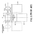
- Fig. 5 shows another conventional pan-tilt drive unit apparatus.
- the pan-tilt drive unit apparatus also has a support member 506 on which a monitoring camera is mounted, and differs from the pan-tilt drive unit apparatus shown in Fig. 4 in a mechanism for rotation in a tilt direction.
- pan-tilt drive unit apparatus shown in Fig. 4 has the tilt motor 411 and the pan motor 401 arranged perpendicularly to each other
- the pan-tilt drive unit apparatus shown in Fig. 5 has a pan motor 501 and a tilt motor 511 arranged side by side substantially in parallel with a rotation axis L2. This arrangement is used to minimize space (operation space) occupied by the pan-tilt drive unit apparatus rotating in a pan direction.
- decelerating mechanisms 517A and 517B are coupled to the tilt motor 511, and the support member 506 is coupled to the decelerating mechanism 517B.
- a decelerating mechanism 507 is coupled to the pan motor 501, and a case 521 to which the support member 506 is fixed is coupled to the decelerating mechanism 507.
- the camera when a monitoring camera is mounted on the support member, the camera is preferably arranged on the rotation axes for pan and tilt (L1 and L2). This is because the camera can be rotated easily in an intended direction and the apparatus (a pan-tilt zoom unit apparatus) can be miniaturized as a whole.
- the pan-tilt drive unit apparatus shown in Fig. 4 if a camera is arranged on the rotation axes for pan and tilt (L1 and L2) and the pan motor 401 is driven, the tilt motor 411 is rotated in the pan direction together with the camera.
- the pan motor 401 is arranged at a position which does not overlies the rotation trajectory of the tilt motor 411 to avoid interference with the rotation of the tilt motor 411 in the pan direction.
- the pan motor 501 and the tilt motor 511 are arranged substantially in parallel to reduce the space (operation space) occupied by the tilt motor 511 moving during rotation in the pan direction.
- the operation space of the whole apparatus can be miniaturized as compared with the pan-tilt drive unit apparatus shown in Fig. 4.
- the minimum space required in addition to the space occupied by the driven member such as a camera includes the space for arranging the pan motor, the space for arranging the tilt motor, and the space for ensuring the rotation trajectory of the tilt motor.
- the tilt motor is arranged only on one side of an output shaft of the pan motor, so that the mass centered on the output shaft of the pan motor is out of balance.
- highly accurate driving is difficult to achieve.
- pan-tilt drive unit apparatuses are increased in size.
- a contemplated approach is to provide a weight on the opposite side to the tilt motor to adjust the mass balance around the output shaft of the pan motor.
- the pan motor requires a higher driving torque corresponding to the added weight, which represses a miniaturization in size of the pan motor.
- pan-tilt drive unit apparatus having a structure in which a pan motor is rotated together with a driven member when a tilt motor is driven.
- a two-axial rotational driving apparatus comprising a first rotation member and a second rotation member which are rotatable independently of each other around a first axis, a support member on which a driven member is mounted, a first actuator which rotationally drives the support member around the first axis through the first rotation member, a second actuator which rotationally drives the second rotation member, a converting mechanism which converts rotation of the second rotation member into rotation around a second axis extending in a direction different from the first axis to rotate the support member around the second axis.
- Fig. 1 is a section view of a two-axial rotational driving apparatus which is Embodiment 1 of the present invention.
- Reference numeral 101 denotes a pan electromagnetic motor
- reference numeral 102 denotes a tilt electromagnetic motor arranged adjacent to the pan motor 101.
- Reference numeral 103 denotes a hollow pan rotation shaft (a second rotation member) which transmits output from the pan motor 101.
- Reference numeral 104 denotes a tilt rotation shaft (a first rotation member) which is arranged on the inner periphery of the pan rotation shaft 103 to transmit output from the tilt motor 102.
- the tilt rotation shaft 104 is rotatably supported by a bearing, not shown, fixed to an upper portion of a housing 106.
- Reference numeral 115 denotes a support member of which orientation can be changed in a pan direction (a direction indicated by an arrow B in Fig. 1) and a tilt direction (a direction indicated by an arrow A in Fig. 1) by the two-axial rotational driving apparatus.
- the support member 115 has a mounting portion 115a on which a camera (a video camera, a television camera, a monitoring camera or the like) 105 is mounted (applied), and a coupling portion 115b which extends downward from one end of the mounting portion 115a.
- the tilt rotation shaft 104 is fixed (coupled) at one end to the coupling portion 115b.
- Reference numeral 107 denotes a base which supports the whole two-axial rotational driving apparatus.
- Reference numeral 108 denotes a bearing which is fixed to the housing 106 and rotatably supports the housing 106 with respect to a second bevel gear 110, later described.
- Reference numeral 109 denotes a first bevel gear which is fixed to another end side of the pan rotation shaft 103 (the another end side means the opposite to the coupling portion 115b of the motors 101 and 102, and this definition applies to the following description), is rotated with the pan rotation shaft 103 together, and engages with the second bevel gear 110.
- the second bevel gear 110 has a shaft portion at the center in a diameter direction, and the shaft portion is fixed to the base 107.
- Reference numeral 111 denotes a pan-encoder scale which is fixed to the first bevel gear 109 and is rotated with the first bevel gear 109 and the pan rotation shaft 103 together.
- Reference numeral 112 denotes a head which is fixed to the housing 106 at a position opposite to the pan-encoder scale 111.
- the pan-encoder scale 111 and the head 112 constitute an encoder unit which detects a driving amount of the pan motor 101.
- Reference numeral 113 denotes a tilt-encoder scale which is fixed to the other end of the tilt rotation shaft 104 and is rotated with the tilt rotation shaft 104 together.
- Reference numeral 114 denotes a head which is fixed to the housing 106 at a position opposite to the tilt-encoder scale 113.
- the tilt encoder scale 113 and the head 114 constitute an encoder unit which detects a driving amount of the tilt motor 102.
- a driving circuit 150 which drives the motors 102 and 103 is provided for the two-axial rotational driving apparatus.
- a control unit (such as a personal computer and an operation unit) 160 serving as a controller is provided at a position away from the apparatus.
- a control signal for directing pan driving or tilt driving is input to the driving circuit 150 from the control unit 160 through a communication channel such as a LAN channel (wired or wireless), the Internet, Ethernet®, and a dedicated channel.
- the driving circuit 150 drives the motors 101 and 102 based on the input control signal and a detected signal from the respective encoder units.
- the control unit 160 can also control operation of the camera 105 (including zooming, focusing, start and stop of image-taking and the like). This realizes an image-taking system (a driven member rotation control system). Such a structure applies to Embodiment 2 later described, although not shown.
- the tilt motor 102 When the tilt motor 102 is driven, its output is transmitted to the support member 115 through the tilt rotation shaft 104 which is rotated about a tilt axis (a first axis) T, thereby rotating the support member 115 and the camera 105 in the tilt direction (the direction shown by the arrow A in Fig. 1).
- the pan motor 101 When the pan motor 101 is driven, output from the pan rotation shaft 103 which is rotated about the same axis (the tilt axis T) as the tilt rotation shaft 104 is transmitted to the first bevel gear 109. Since the second bevel gear 110 is fixed to the base 107, the first bevel gear 109 is revolved about a pan axis (a second axis) P with respect to the second bevel gear 110. In other words, the rotation of the pan rotation shaft 103 about the tilt axis T is converted into the rotation about the pan axis P perpendicular to the tilt axis T.
- the housing 106 is supported by the bearing 108 rotatably with respect to the second bevel gear 110, the motors 101 and 102, the rotation shafts 103 and 104, the support member 115, and the camera 105 rotate about the pan axis P as the center together, depending on the revolution of the first bevel gear 109.
- the pan motor 101 and the tilt motor 102 are arranged adjacent to each other on the tilt axis T (arranged particularly in contact with each other), the space (volume) occupied by the motors 101 and 102 in the apparatus is minimized.
- the tilt rotation shaft 104 is arranged inside the pan rotation shaft 103, the space (volume) occupied by the two rotation shafts 103 and 104 in the apparatus is also minimized. As a result, the apparatus can be miniaturized as a whole.
- the two actuators are arranged on the same axis (the tilt axis T), it is easy to realize an arrangement with stable balance of the two actuators around the pan axis P, that is, a well-balanced mass and largely overlapping rotation areas, as compared with the conventional examples.
- the pan motor 101 and the tilt motor 102 are arranged on both sides of the pan axis P or with the pan axis P as the center (and in addition, the support member 115 and the camera 105 are arranged near the pan axis P to cause tilt rotation along upper portions of the peripheries of the motors 101 and 102).
- the mass of the motors 101 and 102 and even the whole apparatus can be arranged nearly equally on both sides of the pan axis P as the center without providing an extra weight or the like. Consequently, it is possible to reduce vibrations during pan rotation and deterioration of stop accuracy as compared with the conventional examples.
- pan motor 101 and the tilt motor 102 arranged adjacent to each other allow the two motors 101 and 102 to be arranged on the internal diameter side of the second bevel gear 110 which forms the actual axis in the pan direction.
- the rotation trajectories of the two motors 101 and 102 can overlap or be superposed.
- the tilt rotation shaft 104 arranged inside the pan rotation shaft 103 enables the rotation shafts 103 and 104 to be extended coaxially on one side (on the other end side) of the tilt axis T, so that the two encoder units which detect rotation of the rotation shafts 103 and 104 (that is, rotation of the motors 101 and 102) can be arranged collectively and coaxially on the one side (on the other end side) of the tilt axis T. Since the tilt rotation shaft 104 is coupled at the one end side, opposite to the encoder units, to the support member 115, the rotation trajectories (rotation space) of the encoder units and the coupling portion 115b generally overlap or are superposed. It is thus possible to easily realize the arrangement of the two actuators on the same axis and the arrangement of the encoder units serving as detectors with small space.
- the two bevel gears 109 and 110 are arranged by using the space between the two motors 101 and 102 and the encoder units and the space along lower portions of the peripheries of the motors 101 and 102.
- the two bevel gears 109 and 110 are arranged to occupy both the spatial areas described above. This can realize the efficient arrangement to repress an enlargement of the apparatus even when the apparatus has the bevel gears (converting mechanisms) 109 and 110 which are relatively large members.
- Embodiment 1 has the two motors arranged on the tilt axis T in the order of the pan motor 101 and the tilt motor 102 from the encoder units, the order is reversed.
- the tilt rotation shaft 104 is arranged inside the pan rotation shaft 103 in Embodiment 1, but the pan rotation shaft 103 may be arranged inside the tilt rotation shaft 104.
- the two motors are arranged on the tilt axis T in Embodiment 1, the two motors may be arranged on the pan axis P.
- the position of the camera 105 serving as a driven member is not limited to the position shown in Fig. 1.
- the camera 105 may be provided on an extension line of the one end of the tilt rotation shaft 104.
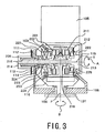
- Fig. 3 shows a section view of a two-axial rotational driving apparatus which is Embodiment 2 of the present invention. While Embodiment 1 applies the electromagnetic motors as the actuators of the two-axial rotational driving apparatus, Embodiment 2 applies vibration type motors (also referred to as ultrasonic motors or the like) as actuators.
- Embodiment 1 applies the electromagnetic motors as the actuators of the two-axial rotational driving apparatus
- Embodiment 2 applies vibration type motors (also referred to as ultrasonic motors or the like) as actuators.
- the vibration type motor used in Embodiment 2 has a vibrating member which comprises of elastic body (a vibrating body) made of metal or the like formed in an annular shape and a piezoelectric element (an electro-mechanical energy conversion element) fixed to a bottom surface of the elastic body and having a predetermined electrode pattern formed thereon. A plurality of frequency waves signals with different phases are applied to the piezoelectric element to generate a traveling wave on a surface of the elastic body.
- a plurality of standing waves formed by the plurality of frequency waves signals are provided with a predetermined phase difference in time (two standing waves: the phase deference is 90 degrees, three standing waves: the phase deference is 120 degrees.), the plurality of standing waves are combined to generate a traveling wave which travels along the annular ring shape on the surface of the elastic body.
- each material particle on the surface of the elastic body is in elliptic motion.
- the easiest method of bringing the rotor into press contact with the elastic body is to press the rotor against the elastic body by a spring, and the pressurizing force is readily adjusted in this method.
- Embodiment 2 Basic structures in Embodiment 2 are similar to those in Embodiment 1, including a pan actuator and a tilt actuator arranged adjacent to each other on a tilt axis T, encoder units arranged collectively on one side of the tilt axis (on the opposite side to a coupling portion of a support member to a tilt rotation shaft across the motors), rotation about the tilt axis T converted into rotation about a pan axis P with bevel gears, and the like.
- the following description is focused on structures different from those in Embodiment 1. Components identical to those in Embodiment 1 are designated with the same reference numerals in Embodiment 1 and description thereof is omitted.
- the two vibration type motors serving as the actuators are arranged adjacent to each other in Embodiment 2.
- the two vibration type motors are arranged opposite to each other such that the elastic bodies thereof are opposed to each other.
- Reference numeral 201 denotes a first vibrating member
- reference numeral 211 denotes a second vibrating member.
- Each of the vibrating members is formed by fixing a piezoelectric element to an elastic body made of metal or the like, as described above.
- a flexible printed board for supplying a driving signal (a frequency waves signal) is fixed to the piezoelectric element.
- Both the vibrating members 201 and 211 are fixed to a housing 106.
- Reference numeral 202 denotes a rotor in contact with a sliding member (designated with no reference numeral) provided on a surface of the elastic body of the first vibrating member 201.
- Reference numeral 212 denotes a rotor in contact with a sliding member (designated with no reference numeral) provided on a surface of the second vibrating member 211.
- the first vibrating member 201 and the rotor 202 constitute a pan vibration type motor.
- the second vibrating member 211 and the rotor 212 constitute a tilt vibration type motor.
- Reference numeral 203 denotes a first bevel gear fixed to the rotor 202.
- the first bevel gear 203 engages with a second bevel gear 110 fixed to a base 107, similarly to Embodiment 1.
- Reference numeral 213 denotes a tilt rotation shaft which extends through an inner side of the first vibrating member 201, the rotor 202, and the first bevel gear 203.
- the rotor 212 of the tilt vibration type motor is coupled to one end of the tilt rotation shaft 213 such that they can be rotated together.
- a support member 115 is also coupled to the one end of the tilt rotation shaft 213.
- a camera 105 serving as a driven member is fixed to the support member 115.
- a cylindrical case 214 is fixed to the other end of the tilt rotation shaft 213.
- the tilt rotation shaft 213 is rotatably supported by a bush 216 arranged at the center of the vibrating members 201 and 211 fixed each to the housing 106 such that the tilt rotation shaft 213 is in a state allowed a movement in a thrust direction.
- a bearing 204 is arranged at the center of the first bevel gear 203.
- An outer ring of the bearing 204 is fixed to the first bevel gear 203.
- An inner ring thereof is fitted in to the tilt rotation shaft 213 to allow the movement in the thrust direction.
- a spring case 215 and a coil spring 205 are arranged between the inner ring of the bearing 204 and the case 214.
- the coil spring 205 energizes the case 214 and the tilt rotation shaft 213 to the left in Fig. 3, and energizes the bearing 204 and the first bevel gear 203 to the right in Fig. 3 through the spring case 215. Therefore a pressurizing mechanism shared between both the vibration type motors is constituted, the pressurizing mechanism presses the rotor 212 fixed to the tilt rotation shaft 213 against the second vibrating member 211, and at the same time, presses the rotor 202 fixed to the first bevel gear 203 against the first vibrating member 201.
- the coil spring 205 is used by preference as a pressurizing mechanism with readiness of fine adjustments of a pressurizing force due to a smaller spring constant than a conical spring, for example.
- each vibration type motor should need a pressurizing mechanism.
- the rotors of the two vibration type motors can simultaneously be brought into press contact with the vibrating members by the single coil spring 205.
- Embodiment 2 employs, as the first and second actuators, the vibration type motors which each produce opposite rotation (relative rotation) of the vibrating member on which vibrations are excited by electro-mechanical energy conversion and the contacting member in press contact with the vibrating member, and the pressurizing mechanism which generates the pressing force for bringing the vibrating member into press contact with the contacting member is shared between both the vibration type motors, thereby reducing space occupied by the pressurizing mechanism, as compared with the case where a pressurizing mechanism is provided for each of the vibration type motors.
- the pressurizing mechanism is shared between both the vibration type motors as described above, the pressing force acts equally on both the vibration type motors. This can eliminate deviation (imbalance) of amounts of wear caused between the vibrating members and the contacting members of the vibration type motors to provide a longer life of the apparatus.
- the coil spring is used by preference as described above, the coil spring involves a large displacement amount to need correspondingly storage space for arrangement thereof. Thus, the structure requiring the only one coil spring can aid a reduction in size of the apparatus.
- both the vibration type motors are sealed by seal members 221, 222, 223, and lids 224 and 225.
- Embodiment 2 similarly to Embodiment 1, the tilt rotation shaft 213 which is driven by the tilt vibration type motor is arranged inside a pan rotation shaft 103 which is driven by the pan vibration type motor.
- first bevel gear 203 and the tilt rotation shaft 213 coupled respectively, to the rotors 202 and 212, are arranged through the bearing 204, they can be rotated independently.
- the pan vibration type motor is driven, the first bevel gear 203 is revolved about the pan axis P with respect to the second bevel gear 110. Therefore, the housing 106, the vibration type motors, the support member 115, and the camera 105 are rotated in the pan direction.
- the tilt vibration type motor is driven to rotate the tilt rotation shaft 213, the support member 115 and the camera 105 are rotated in the tilt direction.
- the rotations caused by driving the respective motors as described above are similar to those in Embodiment 1.
- Embodiment 2 the mass centered on the pan axis P of the motors is arranged nearly equally on both sides.
- the rotation trajectories of both the motors can overlap or be superposed.
- the rotation trajectories of the encoder units and the coupling portion of the support member to the tilt rotation shaft generally overlap or are superposed.
- An increased size of the apparatus can be repressed even it has the bevel gears.
- these characteristics enable a miniaturization in size of the apparatus and rotational driving with higher accuracy.
- Embodiment 2 has the two motors arranged on the tilt axis T in the order of the pan motor and the tilt motor from the encoder units, the order is reversed.
- the tilt rotation shaft is arranged inside the pan rotation shaft in Embodiment 2, but the pan rotation shaft may be arranged inside the tilt rotation shaft.
- the two motors are arranged on the tilt axis T in Embodiment 2, the two motors may be arranged on the pan axis P.
- the position of the camera 105 serving as a driven member is not limited to the position shown in Fig. 3.
- the camera 105 may be provided on an extension ling of the one end of the tilt rotation shaft 203.
- Embodiments 1 and 2 has been described for the two-axial rotational driving apparatus which drives the camera as the driven member, a driven member other than the camera may be mounted on and driven by the two-axial rotational driving apparatus of each of Embodiments 1 and 2.
- a two-axial rotational driving apparatus which achieves a small size and rotational driving with a well-balanced arrangement and higher accuracy.
- the two-axial rotational driving apparatus comprises a first actuator which rotationally drives a support member on which a driven member is mounted around a first axis through a first rotation member, a second actuator which rotationally drives a second rotation member, a converting mechanism which converts rotation of the second rotation member into rotation around a second axis to rotate the support member around the second axis.
Landscapes
- Engineering & Computer Science (AREA)
- General Engineering & Computer Science (AREA)
- Mechanical Engineering (AREA)
- Accessories Of Cameras (AREA)
- Studio Devices (AREA)
- Connection Of Motors, Electrical Generators, Mechanical Devices, And The Like (AREA)
- Transmission Devices (AREA)
Abstract
Description
Claims (12)
- A two-axial rotational driving apparatus characterized by comprising:a first rotation member and a second rotation member which are rotatable independently of each other around a first axis;a support member on which a driven member is mounted;a first actuator which rotationally drives the support member around the first axis through the first rotation member;a second actuator which rotationally drives the second rotation member;a converting mechanism which converts rotation of the second rotation member into rotation around a second axis extending in a direction different from the first axis to rotate the support member around the second axis.
- The two-axial rotational driving apparatus according to claim 1, further characterized by comprising:wherein the first actuator and the second actuator are arranged on the first axis, and a coupling portion of the support member to the first rotation member and the first and second detectors are provided on opposite sides of the first and second actuators in a direction of the first axis.a first detector which detects a driving amount of the first actuator; anda second detector which detects a driving amount of the second actuator,
- The two-axial rotational driving apparatus according to claim 1 or 2, characterized in that the first actuator and the second actuator are arranged adjacent to each other on the first axis.
- The two-axial rotational driving apparatus according to any one of claims 1 to 3, characterized in that the first actuator and the second actuator are arranged on both sides of the second axis on the first axis.
- The two-axial rotational driving apparatus according to any one of claims 1 to 4, characterized in that one of the first and second rotation members is arranged inside the other.
- The two-axial rotational driving apparatus according to claim 2, characterized in that n the converting mechanism is arranged by using a first space between the first and second actuators and the first and second detectors and a second space along peripheries of the first and second actuators.
- The two-axial rotational driving apparatus according to claim 1, characterized in that a portion of the support member where the driven member is applied is rotated around the first axis along peripheries of the first and second actuators.
- The two-axial rotational driving apparatus according to claim 1, characterized in that each of the first and second actuators is a vibration type motor which produces relative rotation of a vibrating member on which vibrations are excited through electro-mechanical energy conversion and a contacting member in press contact with the vibrating member, and a pressurizing mechanism which produces a pressing force for bringing the vibrating member into press contact with the contacting member is shared between both the vibration type motors.
- A driven member rotation control system characterized by comprising:the two-axial rotational driving apparatus according to claim 1; anda driven member which is mounted on the support member.
- The driven member rotation control system according to claim 9, characterized in that the driven member is an image-taking apparatus.
- The driven member rotation control system according to claim 9, further characterized by comprising a controller which controls operation of the first and second actuators.
- The driven member rotation control system according to claim 11, characterized in that the controller controls operation of the driven member.
Applications Claiming Priority (2)
| Application Number | Priority Date | Filing Date | Title |
|---|---|---|---|
| JP2003270475 | 2003-07-02 | ||
| JP2003270475A JP4058392B2 (en) | 2003-07-02 | 2003-07-02 | Two-axis rotary table device and driven body rotation control system |
Publications (3)
| Publication Number | Publication Date |
|---|---|
| EP1493959A2 true EP1493959A2 (en) | 2005-01-05 |
| EP1493959A3 EP1493959A3 (en) | 2005-06-22 |
| EP1493959B1 EP1493959B1 (en) | 2006-10-11 |
Family
ID=33432376
Family Applications (1)
| Application Number | Title | Priority Date | Filing Date |
|---|---|---|---|
| EP04015484A Expired - Lifetime EP1493959B1 (en) | 2003-07-02 | 2004-07-01 | Two-axial rotational driving apparatus and driven member rotation control system |
Country Status (4)
| Country | Link |
|---|---|
| US (1) | US7626633B2 (en) |
| EP (1) | EP1493959B1 (en) |
| JP (1) | JP4058392B2 (en) |
| DE (1) | DE602004002731T2 (en) |
Cited By (3)
| Publication number | Priority date | Publication date | Assignee | Title |
|---|---|---|---|---|
| CN103581514A (en) * | 2012-08-06 | 2014-02-12 | 苏州工业园区凯艺精密科技有限公司 | Automatic tracking, recording and broadcasting device |
| EP3657249A1 (en) * | 2018-11-01 | 2020-05-27 | Canon Kabushiki Kaisha | Imaging apparatus |
| CN115493039A (en) * | 2022-09-22 | 2022-12-20 | 上海勤芸电子科技有限公司 | Transmission mechanism and electronic device |
Families Citing this family (16)
| Publication number | Priority date | Publication date | Assignee | Title |
|---|---|---|---|---|
| KR20100102959A (en) * | 2009-03-12 | 2010-09-27 | 삼성테크윈 주식회사 | Firearm system having camera unit with adjustable optical axis |
| WO2011025273A2 (en) * | 2009-08-25 | 2011-03-03 | 주식회사 제우스 | Dual line production apparatus having a camera-alternating system for producing solar cells, and production method thereof |
| GB2492625B (en) * | 2011-06-06 | 2014-12-03 | Canon Kk | Driving apparatus, camera platform apparatus and driving method of controlling the driving apparatus |
| US9182070B2 (en) * | 2012-04-30 | 2015-11-10 | Threat Spectrum Inc. | Positioning device |
| JP6075996B2 (en) * | 2012-08-24 | 2017-02-08 | 日本電産サンキョー株式会社 | The camera module |
| US9106814B2 (en) * | 2012-11-14 | 2015-08-11 | The United States of America as represented by the Federal Bureau of Investigation, Dept. of Justice | Apparatuses for rotating a sensing device |
| DE202013000087U1 (en) * | 2013-01-04 | 2014-01-08 | Vitec Videocom GmbH | Follow Focus |
| JP2016070303A (en) * | 2014-09-26 | 2016-05-09 | 日本パルスモーター株式会社 | Work body operation device |
| CN105817905B (en) * | 2016-05-28 | 2017-12-22 | 陈春良 | A kind of variable-ratio slewing equipment |
| JP7150492B2 (en) * | 2017-08-31 | 2022-10-11 | キヤノン株式会社 | Imaging device |
| JP2020067155A (en) * | 2018-10-25 | 2020-04-30 | 株式会社エアロネクスト | Gimbal mechanism |
| JP7373326B2 (en) * | 2018-11-01 | 2023-11-02 | キヤノン株式会社 | Photography equipment |
| CN111262387A (en) * | 2020-04-15 | 2020-06-09 | 深圳市仟仪科技有限公司 | A dual-shaft output device, electric manicurizer |
| TWI786712B (en) | 2021-07-07 | 2022-12-11 | 明泰科技股份有限公司 | Rotation apparatus being able to rotate around different axes with one motor and camera using the same |
| CN117346017B (en) * | 2023-11-15 | 2024-08-16 | 深圳市东舜时代科技有限公司 | Extensible monitoring equipment holder and application method thereof |
| CN120820232A (en) * | 2025-09-16 | 2025-10-21 | 福建省计量科学研究院(福建省眼镜质量检验站) | A visual positioning calibration fixture for digital vibration measurement instrument traceability |
Family Cites Families (14)
| Publication number | Priority date | Publication date | Assignee | Title |
|---|---|---|---|---|
| US4353110A (en) * | 1980-09-12 | 1982-10-05 | Ellis Richard D | Search and warning light system |
| US4379624A (en) | 1981-04-13 | 1983-04-12 | The United States Of America As Represented By The Secretary Of The Navy | Laser beam steering device |
| US4945367A (en) * | 1988-03-02 | 1990-07-31 | Blackshear David M | Surveillance camera system |
| US5028997A (en) * | 1989-07-20 | 1991-07-02 | Elbex Video Kabushiki Kaisha | Television camera apparatus |
| JPH05281370A (en) * | 1992-03-31 | 1993-10-29 | Seiko Instr Inc | Analog electronic timepiece |
| FR2704050B1 (en) | 1993-04-15 | 1995-06-09 | Giat Ind Sa | Orientable support system for mission equipment mounted on a fixed or mobile carrier. |
| US6098484A (en) * | 1995-07-10 | 2000-08-08 | Kensington Laboratories, Inc. | High torque, low hysteresis, multiple link robot arm mechanism |
| JP3715718B2 (en) * | 1996-07-17 | 2005-11-16 | キヤノン株式会社 | Imaging device |
| US5850579A (en) * | 1997-06-09 | 1998-12-15 | Addco, Inc. | Pan/tilt support with concentric drive shafts |
| US6027257A (en) | 1998-03-26 | 2000-02-22 | Basic Telepresence Inc | Pan and tilt unit |
| US6356308B1 (en) * | 1998-06-11 | 2002-03-12 | Polycom, Inc. | Device for rotatably positioning a camera or similar article about two orthogonal axes |
| JP2000047292A (en) | 1998-07-30 | 2000-02-18 | Yokogawa Electric Corp | Pan-tilt camera device |
| JP2000047202A (en) | 1998-07-31 | 2000-02-18 | Kyocera Corp | Reflective liquid crystal display |
| US6679490B2 (en) * | 2002-01-25 | 2004-01-20 | Bowe Bell + Howell Scanners, L.L.C. | PIC roller with clutch |
-
2003
- 2003-07-02 JP JP2003270475A patent/JP4058392B2/en not_active Expired - Fee Related
-
2004
- 2004-06-29 US US10/879,294 patent/US7626633B2/en active Active
- 2004-07-01 EP EP04015484A patent/EP1493959B1/en not_active Expired - Lifetime
- 2004-07-01 DE DE602004002731T patent/DE602004002731T2/en not_active Expired - Lifetime
Cited By (5)
| Publication number | Priority date | Publication date | Assignee | Title |
|---|---|---|---|---|
| CN103581514A (en) * | 2012-08-06 | 2014-02-12 | 苏州工业园区凯艺精密科技有限公司 | Automatic tracking, recording and broadcasting device |
| EP3657249A1 (en) * | 2018-11-01 | 2020-05-27 | Canon Kabushiki Kaisha | Imaging apparatus |
| US11064097B2 (en) | 2018-11-01 | 2021-07-13 | Canon Kabushiki Kaisha | Imaging apparatus for adjusting pressing forces of an ultrasonic motor and a waterproof member |
| CN115493039A (en) * | 2022-09-22 | 2022-12-20 | 上海勤芸电子科技有限公司 | Transmission mechanism and electronic device |
| CN115493039B (en) * | 2022-09-22 | 2024-06-04 | 上海勤芸电子科技有限公司 | Transmission mechanism and electronic equipment |
Also Published As
| Publication number | Publication date |
|---|---|
| DE602004002731D1 (en) | 2006-11-23 |
| US7626633B2 (en) | 2009-12-01 |
| EP1493959B1 (en) | 2006-10-11 |
| JP4058392B2 (en) | 2008-03-05 |
| JP2005024074A (en) | 2005-01-27 |
| US20070108354A1 (en) | 2007-05-17 |
| DE602004002731T2 (en) | 2007-08-16 |
| EP1493959A3 (en) | 2005-06-22 |
Similar Documents
| Publication | Publication Date | Title |
|---|---|---|
| EP1493959B1 (en) | Two-axial rotational driving apparatus and driven member rotation control system | |
| JP2005234230A (en) | Pan head device | |
| JP2007041455A (en) | Image blur correction device for optical device | |
| JP2003301994A (en) | Bearing integrated rotation device | |
| US20190165697A1 (en) | Vibration type motor, lens apparatus, and electronic apparatus | |
| TWI393435B (en) | Camera control apparatus, shooting direction control method and carera apparatus | |
| JP3489531B2 (en) | Two-axis drive mechanism, image input device and light projection device using the same | |
| KR20100105653A (en) | Vibration actuator and imager | |
| JP2002112562A (en) | Driving unit | |
| US7193353B2 (en) | Operating apparatus and an electric instrument | |
| US10917024B2 (en) | Vibration-type drive apparatus, robot, image forming apparatus, and image pickup apparatus that inhibit undesired vibration | |
| JP4297691B2 (en) | Pan head and camera system | |
| JP2020089236A (en) | Vibration wave motor and electronic device having the same | |
| JP2016208732A (en) | Vibrator, vibration type drive device, image forming apparatus, robot, and pan head device | |
| US20100073787A1 (en) | Piezoelectric-driving optical lens | |
| JP4328731B2 (en) | Pan head device and pan head system | |
| WO2007105489A1 (en) | Ultrasonic actuator | |
| JP3124284B2 (en) | Vibration wave drive | |
| EP3995890B1 (en) | Pan or tilt head and imaging device | |
| JP4365926B2 (en) | Lens barrel with vibratory drive | |
| JP2019080393A (en) | Vibration type actuator and electronic apparatus including the same | |
| JP3164857B2 (en) | Vibration wave drive device and device equipped with vibration wave drive device | |
| KR100380821B1 (en) | Angular moving apparatus having piezo-electric element | |
| US7483651B2 (en) | Drive device used in image forming device | |
| JP4710527B2 (en) | Drive mechanism and device provided with drive mechanism |
Legal Events
| Date | Code | Title | Description |
|---|---|---|---|
| PUAI | Public reference made under article 153(3) epc to a published international application that has entered the european phase |
Free format text: ORIGINAL CODE: 0009012 |
|
| AK | Designated contracting states |
Kind code of ref document: A2 Designated state(s): AT BE BG CH CY CZ DE DK EE ES FI FR GB GR HU IE IT LI LU MC NL PL PT RO SE SI SK TR |
|
| AX | Request for extension of the european patent |
Extension state: AL HR LT LV MK |
|
| PUAL | Search report despatched |
Free format text: ORIGINAL CODE: 0009013 |
|
| AK | Designated contracting states |
Kind code of ref document: A3 Designated state(s): AT BE BG CH CY CZ DE DK EE ES FI FR GB GR HU IE IT LI LU MC NL PL PT RO SE SI SK TR |
|
| AX | Request for extension of the european patent |
Extension state: AL HR LT LV MK |
|
| 17P | Request for examination filed |
Effective date: 20051028 |
|
| AKX | Designation fees paid |
Designated state(s): DE FR GB |
|
| GRAP | Despatch of communication of intention to grant a patent |
Free format text: ORIGINAL CODE: EPIDOSNIGR1 |
|
| GRAS | Grant fee paid |
Free format text: ORIGINAL CODE: EPIDOSNIGR3 |
|
| GRAA | (expected) grant |
Free format text: ORIGINAL CODE: 0009210 |
|
| AK | Designated contracting states |
Kind code of ref document: B1 Designated state(s): DE FR GB |
|
| REG | Reference to a national code |
Ref country code: GB Ref legal event code: FG4D |
|
| REF | Corresponds to: |
Ref document number: 602004002731 Country of ref document: DE Date of ref document: 20061123 Kind code of ref document: P |
|
| ET | Fr: translation filed | ||
| PLBE | No opposition filed within time limit |
Free format text: ORIGINAL CODE: 0009261 |
|
| STAA | Information on the status of an ep patent application or granted ep patent |
Free format text: STATUS: NO OPPOSITION FILED WITHIN TIME LIMIT |
|
| 26N | No opposition filed |
Effective date: 20070712 |
|
| REG | Reference to a national code |
Ref country code: FR Ref legal event code: PLFP Year of fee payment: 13 |
|
| REG | Reference to a national code |
Ref country code: FR Ref legal event code: PLFP Year of fee payment: 14 |
|
| REG | Reference to a national code |
Ref country code: FR Ref legal event code: PLFP Year of fee payment: 15 |
|
| PGFP | Annual fee paid to national office [announced via postgrant information from national office to epo] |
Ref country code: FR Payment date: 20190619 Year of fee payment: 16 |
|
| PGFP | Annual fee paid to national office [announced via postgrant information from national office to epo] |
Ref country code: GB Payment date: 20190626 Year of fee payment: 16 Ref country code: DE Payment date: 20190618 Year of fee payment: 16 |
|
| REG | Reference to a national code |
Ref country code: DE Ref legal event code: R119 Ref document number: 602004002731 Country of ref document: DE |
|
| GBPC | Gb: european patent ceased through non-payment of renewal fee |
Effective date: 20200701 |
|
| PG25 | Lapsed in a contracting state [announced via postgrant information from national office to epo] |
Ref country code: GB Free format text: LAPSE BECAUSE OF NON-PAYMENT OF DUE FEES Effective date: 20200701 Ref country code: FR Free format text: LAPSE BECAUSE OF NON-PAYMENT OF DUE FEES Effective date: 20200731 |
|
| PG25 | Lapsed in a contracting state [announced via postgrant information from national office to epo] |
Ref country code: DE Free format text: LAPSE BECAUSE OF NON-PAYMENT OF DUE FEES Effective date: 20210202 |