EP1493920A2 - Ignition timing control system - Google Patents
Ignition timing control system Download PDFInfo
- Publication number
- EP1493920A2 EP1493920A2 EP04445068A EP04445068A EP1493920A2 EP 1493920 A2 EP1493920 A2 EP 1493920A2 EP 04445068 A EP04445068 A EP 04445068A EP 04445068 A EP04445068 A EP 04445068A EP 1493920 A2 EP1493920 A2 EP 1493920A2
- Authority
- EP
- European Patent Office
- Prior art keywords
- ignition position
- engine
- exhaust system
- temperature
- cylinder
- Prior art date
- Legal status (The legal status is an assumption and is not a legal conclusion. Google has not performed a legal analysis and makes no representation as to the accuracy of the status listed.)
- Withdrawn
Links
Images


Classifications
-
- F—MECHANICAL ENGINEERING; LIGHTING; HEATING; WEAPONS; BLASTING
- F02—COMBUSTION ENGINES; HOT-GAS OR COMBUSTION-PRODUCT ENGINE PLANTS
- F02P—IGNITION, OTHER THAN COMPRESSION IGNITION, FOR INTERNAL-COMBUSTION ENGINES; TESTING OF IGNITION TIMING IN COMPRESSION-IGNITION ENGINES
- F02P5/00—Advancing or retarding ignition; Control therefor
- F02P5/04—Advancing or retarding ignition; Control therefor automatically, as a function of the working conditions of the engine or vehicle or of the atmospheric conditions
Definitions
- the control system may include an exhaust sensor for sensing the temperature of the exhaust system.
- the control system also may include a display for displaying the temperature of the exhaust system.
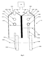
- the piston 116 and a crank web 120 are connected with a connecting rod 118 such that the connecting rod 118 pivots where it attaches to both the piston 116 and the crank web 120, so that as the piston 116 moves up and down in the cylinder 112, the crank web 120 turns about its axis of rotation 122.
- the degree to which the ignition position is changed may vary from embodiment to embodiment. In addition, the degree to which the ignition position is changed may vary depending upon the circumstances, i.e. engine speed or temperature, ambient conditions, fuel mix, etc.
- the ignition changer 156 may retard the ignition position from the normal operating ignition position for the engine by at least 35 degrees.
- a variety of displays 160 may be suitable for use with the invention.
- a gauge or readout indicating the temperature of the exhaust system 150 may be provided in a location accessible to the vehicle operator, i.e. on the vehicle's control panel.
- Such an arrangement is exemplary only.
- Other displays 160 including but not limited to "idiot lights" indicating that the exhaust system 150 is or is not at a desired temperature, may be equally suitable.
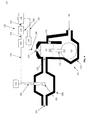
- the activator 158 may automatic. That is, the activator 158 may be activated, deactivated, and/or adjusted least partially by the system 100.
- a system 100 with an automatic activator 158 may include a controller 172 for controlling the ignition changer 156. That is, in the embodiment described herein, when the activator 158 is activated, the controller 172 controls when, how, and how much the ignition changer 156 change the ignition position of the engine 110 .
- the comparator 170 receives signals from the exhaust sensor 152 , indicating the temperature of the exhaust system 150.
- the comparator 170 compares the actual temperature of the exhaust system 150 to the desired or tuned temperature of exhaust system 150, and sends a signal to the controller 172 .
- the controller 172 Based on the signal received from the comparator 170 , the controller 172 then sends a signal to the ignition changer 156 as to when, how, and how much the ignition position of the engine 110 should be changed.
- an engine assembly 101 adapted to change its ignition position in accordance with the principles of the present invention is not precluded from otherwise changing its ignition position.
- the operating ignition position of an engine 110 under the control of an engine control system 100 in accordance with the principles of the present invention may vary even when the ignition position is not being changed to warm the exhaust system 150, i.e. the operating ignition position may vary somewhat depending on engine speed or other conditions.
Landscapes
- Engineering & Computer Science (AREA)
- Chemical & Material Sciences (AREA)
- Combustion & Propulsion (AREA)
- Mechanical Engineering (AREA)
- General Engineering & Computer Science (AREA)
- Electrical Control Of Ignition Timing (AREA)
- Combined Controls Of Internal Combustion Engines (AREA)
- Output Control And Ontrol Of Special Type Engine (AREA)
- Electrical Control Of Air Or Fuel Supplied To Internal-Combustion Engine (AREA)
Abstract
Description
Claims (51)
- A method for improving engine performance, comprising:in an engine assembly comprising an engine with at least one cylinder and a piston disposed within said cylinder, and an exhaust system, said cylinder being in communication with said exhaust system,when a temperature of said exhaust system is lower than a target temperature of said exhaust system, igniting said cylinder at a warming ignition position, wherein in said warming ignition position fuel and air propagate from said cylinder to said exhaust system while undergoing combustion, whereby said temperature of said exhaust system increases towards said target temperature; andigniting said cylinder at an operating ignition position when said temperature of said exhaust system is at least equal to said target temperature, wherein a performance of said engine when said temperature of said exhaust system is at least equal to said target temperature is improved over a performance of said engine when said temperature of said exhaust system is less than said target temperature.
- The method according to claim 1, wherein:said engine is a two-cycle engine.
- The method according to claim 1, further comprising:cycling between said warming ignition position and said operating ignition position to maintain said temperature of said exhaust system at least equal to said target temperature.
- The method according to claim 1, wherein:said warming ignition position is retarded from said operating ignition position.
- The method according to claim 4, wherein:said warming ignition position is retarded from said operating ignition position by up to 5 degrees.
- The method according to claim 4, wherein:said warming ignition position is retarded from said operating ignition position by at least 5 degrees.
- The method according to claim 4, wherein:said warming ignition position is retarded from said operating ignition position by at least 10 degrees.
- The method according to claim 4, wherein:said warming ignition position is retarded from said operating ignition position by at least 15 degrees.
- The method according to claim 4, wherein:said warming ignition position is retarded from said operating ignition position by at least 20 degrees.
- The method according to claim 4, wherein:said warming ignition position is retarded from said operating ignition position by at least 25 degrees.
- The method according to claim 4, wherein:said warming ignition position is retarded from said operating ignition position by at least 30 degrees.
- The method according to claim 4, wherein:said warming ignition position is retarded from said operating ignition position by at least 35 degrees.
- The method according to claim 4, wherein:said warming ignition position is retarded from said operating ignition position by at least 40 degrees.
- The method according to claim 4, wherein:said warming ignition position is 10 to 20 degrees after top dead center.
- The method according to claim 1, further comprising:manually changing between said warming ignition position and said operating ignition position.
- The method according to claim 1, further comprising:measuring said temperature of said exhaust system.
- The method according to claim 16, further comprising:displaying an indication of said temperature of said exhaust system to a vehicle operator.
- The method according to claim 16, further comprising:comparing said exhaust temperature with at least one comparison value using a comparator; andautomatically changing between said warming ignition position and said operating ignition position in response to said comparison of said exhaust temperature with said comparison value.
- The method according to claim 1, wherein said engine comprises at least two cylinders, further comprising igniting at least two of said cylinders independently from one another.
- The method according to claim 1, wherein:a rate at which said engine generates at least one pollutant decreases as said temperature of said exhaust system increases towards said target temperature when said engine is ignited at said operating ignition position.
- The method according to claim 1, wherein:a fuel efficiency of said engine increases as said temperature of said exhaust system increases towards said target temperature when said engine is ignited at said operating ignition position.
- The method according to claim 1, wherein:a peak power output of said engine increases as said temperature of said exhaust system increases towards said target temperature when said engine is ignited at said operating ignition position.
- A method of decreasing output of at least one pollutant from an engine, comprising:in an engine assembly comprising an engine with at least one cylinder and a piston disposed within said cylinder, and an exhaust system, said cylinder being in communication with said exhaust system,when a temperature of said exhaust system is lower than a target temperature of said exhaust system, igniting said cylinder at a warming ignition position, wherein in said warming ignition position fuel and air propagate from said cylinder to said exhaust system while undergoing combustion, whereby said temperature of said exhaust system increases towards said target temperature; andigniting said cylinder at an operating ignition position when said temperature of said exhaust system is at least equal to said target temperature, wherein an output of at least one pollutant when said temperature of said exhaust system is at least equal to said target temperature is less than an output of said at least one pollutant when said temperature of said exhaust system is less than said target temperature.
- A method of increasing fuel efficiency of an engine, comprising:in an engine assembly comprising an engine with at least one cylinder and a piston disposed within said cylinder, and an exhaust system, said cylinder being in communication with said exhaust system,when a temperature of said exhaust system is lower than a target temperature of said exhaust system, igniting said cylinder at a warming ignition position, wherein in said warming ignition position fuel and air propagate from said cylinder to said exhaust system while undergoing combustion, whereby said temperature of said exhaust system increases towards said target temperature; andigniting said cylinder at an operating ignition position when said temperature of said exhaust system is at least equal to said target temperature, wherein a fuel efficiency of said engine when said temperature of said exhaust system is at least equal to said target temperature is greater than a fuel efficiency of said engine when said temperature of said exhaust system is less than said target temperature.
- A method of increasing a power output of an engine, comprising:in an engine assembly comprising an engine with at least one cylinder and a piston disposed within said cylinder, and an exhaust system, said cylinder being in communication with said exhaust system,when a temperature of said exhaust system is lower than a target temperature of said exhaust system, igniting said cylinder at a warming ignition position, wherein in said warming ignition position fuel and air propagate from said cylinder to said exhaust system while undergoing combustion, whereby said temperature of said exhaust system increases towards said target temperature; andigniting said cylinder at an operating ignition position when said temperature of said exhaust system is at least equal to said target temperature, wherein a peak power output of said engine when said temperature of said exhaust system is at least equal to said target temperature is greater than a peak power output of said engine when said temperature of said exhaust system is less than said target temperature.
- An engine control system, comprising:an ignition changer for changing an ignition position of a piston in at least one cylinder of an engine to and from a warming ignition position, wherein in said warming ignition position fuel and air propagate from said cylinder to an exhaust system while undergoing combustion, whereby said temperature of said exhaust system increases, said ignition changer being in communication with an igniter for said engine; andan activator for activating said ignition changer, said activator being in communication with said ignition changer.
- The control system according to claim 26, wherein:said warming ignition position is retarded from an operating ignition position for said engine.
- The control system according to claim 27, wherein:said warming ignition position is retarded from said operating ignition position by up to 5 degrees.
- The control system according to claim 27, wherein:said warming ignition position is retarded from said operating ignition position by at least 5 degrees.
- The control system according to claim 27, wherein:said warming ignition position is retarded from said operating ignition position by at least 10 degrees.
- The control system according to claim 27, wherein:said warming ignition position is retarded from said operating ignition position by at least 15 degrees.
- The control system according to claim 27, wherein:said warming ignition position is retarded from said operating ignition position by at least 20 degrees.
- The control system according to claim 27, wherein:said warming ignition position is retarded from said operating ignition position by at least 25 degrees.
- The control system according to claim 27, wherein:said warming ignition position is retarded from said operating ignition position by at least 30 degrees.
- The control system according to claim 27, wherein:said warming ignition position is retarded from said operating ignition position by at least 35 degrees.
- The control system according to claim 27, wherein:said warming ignition position is retarded from said operating ignition position by at least 40 degrees.
- The control system according to claim 27, wherein:said warming ignition position is 10 to 20 degrees after top dead center.
- The control system according to claim 26, wherein:said activator is a manual activator.
- The control system according to claim 26, further comprising:an exhaust sensor for sensing a temperature of said exhaust system.
- The control system according to claim 39, further comprising:a display for displaying an indication of said temperature of said exhaust system.
- The control system according to claim 39, wherein:said activator is an automatic activator, comprising:a comparator for comparing said temperature of said exhaust system with at least one comparison value, said comparator being in communication with said exhaust sensing means; anda controller for automatically changing to and from said warming ignition position in response to said comparison of said exhaust temperature with said at least one comparison value, so as to automatically reach and maintain a target temperature for said exhaust system, said controller being in communication with said comparator and said ignition changer.
- The control system according to claim 26, wherein:said engine comprises at least two cylinders, each cylinder having a piston disposed therein, and said igniter is adapted to independently ignite at least two of said cylinders; andsaid ignition changer is adapted to change said ignition position of said pistons for said at least two independently ignited cylinders to and from said warming ignition position.
- The control system according to claim 26, wherein:a rate at which said engine generates at least one pollutant when said engine is ignited at an operating ignition position decreases as said temperature of said exhaust system increases towards a target temperature.
- The control system according to claim 26, wherein:a fuel efficiency of said engine when said engine is ignited at an operating ignition position increases as said temperature of said exhaust system increases towards a target temperature.
- The control system according to claim 26, wherein:a power output of said engine when said engine is ignited at an operating ignition position increases as said temperature of said exhaust system increases towards a target temperature.
- A method of operating an engine, comprising:in an engine assembly comprising an engine with at least one cylinder and a piston disposed within said cylinder, and an exhaust system, said cylinder being in communication with said exhaust system,igniting said cylinder at a warming ignition position of said piston, such that fuel and air propagate from said cylinder to said exhaust system while undergoing combustion, whereby a temperature of said exhaust system increases towards a target temperature;subsequently igniting said cylinder at an operating ignition position of said piston different from said warming ignition position.
- The method according to claim 46, wherein:said engine is a two-cycle engine.
- The method according to claim 46, wherein:said cylinder is ignited at said warming ignition position until said temperature of said exhaust system reaches said target temperature.
- The method according to claim 46, further comprising:cycling between said warming ignition position and said operating ignition position to maintain said temperature of said exhaust system at least equal to said target temperature.
- An engine assembly, comprising:an engine, said engine comprising at least one cylinder, a piston disposed within said cylinder, and an igniter for igniting fuel and air within said cylinder;an exhaust system in communication with said cylinder; andan engine control system, comprising:an ignition changer for changing an ignition position of said piston to and from a warming ignition position, such that in said warming ignition position fuel and air propagate from said cylinder to said exhaust system while undergoing combustion, whereby a temperature of said exhaust system increases, said ignition changer being in communication with said igniter; andan activator for activating said ignition changer, said activator being in communication with said ignition changer.
- The method according to claim 50, wherein:said engine is a two-cycle engine.
Applications Claiming Priority (2)
| Application Number | Priority Date | Filing Date | Title |
|---|---|---|---|
| US10/454,861 US6951203B2 (en) | 2003-06-05 | 2003-06-05 | Ignition timing control system |
| US454861 | 2003-06-05 |
Publications (2)
| Publication Number | Publication Date |
|---|---|
| EP1493920A2 true EP1493920A2 (en) | 2005-01-05 |
| EP1493920A3 EP1493920A3 (en) | 2005-04-27 |
Family
ID=33434905
Family Applications (1)
| Application Number | Title | Priority Date | Filing Date |
|---|---|---|---|
| EP04445068A Withdrawn EP1493920A3 (en) | 2003-06-05 | 2004-06-04 | Ignition timing control system |
Country Status (3)
| Country | Link |
|---|---|
| US (1) | US6951203B2 (en) |
| EP (1) | EP1493920A3 (en) |
| CA (1) | CA2469990A1 (en) |
Families Citing this family (6)
| Publication number | Priority date | Publication date | Assignee | Title |
|---|---|---|---|---|
| US8260535B2 (en) * | 2007-09-28 | 2012-09-04 | Bombardier Recreational Products Inc. | Load sensor for a vehicle electronic stability system |
| US8647161B2 (en) * | 2009-01-15 | 2014-02-11 | Bombardier Recreational Products Inc. | Method of controlling a personal watercraft |
| CN106794816B (en) | 2014-09-23 | 2020-01-17 | 庞巴迪动力产品公司 | passenger seat for vehicle |
| CA3149782C (en) | 2019-08-30 | 2023-08-15 | Bruno Schuehmacher | Engine assembly and method for controlling an engine |
| US11913390B2 (en) | 2019-08-30 | 2024-02-27 | Bombardier Recreational Products Inc. | Engine assembly and method for controlling an engine |
| CN114233497B (en) * | 2021-12-14 | 2024-02-20 | 潍柴动力股份有限公司 | An engine control method, system and equipment |
Family Cites Families (6)
| Publication number | Priority date | Publication date | Assignee | Title |
|---|---|---|---|---|
| JPH03164549A (en) * | 1989-11-22 | 1991-07-16 | Fuji Heavy Ind Ltd | Engine control device of two-cycle engine |
| DE69421517T2 (en) | 1993-01-25 | 2000-04-27 | Orbital Engine Co. (Australia) Pty. Ltd., Balcatta | METHOD FOR OPERATING AN INTERNAL COMBUSTION ENGINE |
| JPH07229419A (en) * | 1994-02-18 | 1995-08-29 | Toyota Motor Corp | Catalyst warm-up control device for internal combustion engine |
| FR2738595B1 (en) * | 1995-09-08 | 1997-10-17 | Inst Francais Du Petrole | TWO STROKE INTERNAL COMBUSTION ENGINE DEPOLLUTION PROCESS AND RELATED APPLICATIONS |
| US6371082B1 (en) * | 1999-12-01 | 2002-04-16 | Arctic Cat, Inc. | Two-cycle engine with exhaust temperature-controlled ignition timing |
| US6237566B1 (en) * | 1999-12-01 | 2001-05-29 | Arctic Cat Inc. | Two-cycle engine with exhaust temperature-controlled ignition timing |
-
2003
- 2003-06-05 US US10/454,861 patent/US6951203B2/en not_active Expired - Lifetime
-
2004
- 2004-06-03 CA CA002469990A patent/CA2469990A1/en not_active Abandoned
- 2004-06-04 EP EP04445068A patent/EP1493920A3/en not_active Withdrawn
Also Published As
| Publication number | Publication date |
|---|---|
| EP1493920A3 (en) | 2005-04-27 |
| US20040244774A1 (en) | 2004-12-09 |
| US6951203B2 (en) | 2005-10-04 |
| CA2469990A1 (en) | 2004-12-05 |
Similar Documents
| Publication | Publication Date | Title |
|---|---|---|
| US5881552A (en) | Control system for internal combustion engines and control system for vehicles | |
| CN100378316C (en) | Direct fuel injection/spark ignition engine control device | |
| JP5919697B2 (en) | Diesel engine start control device | |
| CN100410514C (en) | engine starter | |
| US5722363A (en) | Cylinder-injection type internal combustion engine and a fuel injection control apparatus therefor | |
| US6910454B2 (en) | Method of and device for operating a multi-cylinder combustion engine with variable compression ratio | |
| EP1891314B1 (en) | Starting system and method of internal combustion engine | |
| EP1989437A1 (en) | Starting system and method of internal combustion engine | |
| US4725955A (en) | Apparatus for controlling ignition timing in an internal combustion engine | |
| EP1741906B1 (en) | Internal combustion engine start-up control | |
| EP0831219A2 (en) | Method for controlling the operation of an internal combustion engine | |
| JP4844537B2 (en) | Engine start control device | |
| US6951203B2 (en) | Ignition timing control system | |
| JP2009228588A (en) | Control device for variable valve train | |
| EP1698780A2 (en) | Starting method and system for internal combustion engine | |
| KR0144106B1 (en) | Throttle valve control apparatus for spark ignition two cycle engines | |
| US5730103A (en) | Fuel supply control system for internal combustion engines | |
| JP4992757B2 (en) | Control method for internal combustion engine | |
| EP0751293A2 (en) | Method for advanced crank spark with blend spark retard for an engine | |
| JPH06200806A (en) | Air-fuel ratio control device of hydrogen engine | |
| EP1544456A2 (en) | Engine starting system | |
| JP2897550B2 (en) | Valve timing control device for internal combustion engine | |
| JP4442303B2 (en) | Engine starter | |
| JPH08246907A (en) | Valve timing control device for internal combustion engine | |
| JP3757998B2 (en) | In-cylinder injection type internal combustion engine control device |
Legal Events
| Date | Code | Title | Description |
|---|---|---|---|
| PUAI | Public reference made under article 153(3) epc to a published international application that has entered the european phase |
Free format text: ORIGINAL CODE: 0009012 |
|
| AK | Designated contracting states |
Kind code of ref document: A2 Designated state(s): AT BE BG CH CY CZ DE DK EE ES FI FR GB GR HU IE IT LI LU MC NL PL PT RO SE SI SK TR |
|
| AX | Request for extension of the european patent |
Extension state: AL HR LT LV MK |
|
| PUAL | Search report despatched |
Free format text: ORIGINAL CODE: 0009013 |
|
| RIC1 | Information provided on ipc code assigned before grant |
Ipc: 7F 02B 61/02 B Ipc: 7F 02P 15/00 B Ipc: 7F 02P 5/02 B Ipc: 7F 02P 5/15 B Ipc: 7F 02P 5/155 B Ipc: 7F 02P 5/04 B Ipc: 7F 02D 37/02 A |
|
| AK | Designated contracting states |
Kind code of ref document: A3 Designated state(s): AT BE BG CH CY CZ DE DK EE ES FI FR GB GR HU IE IT LI LU MC NL PL PT RO SE SI SK TR |
|
| AX | Request for extension of the european patent |
Extension state: AL HR LT LV MK |
|
| 17P | Request for examination filed |
Effective date: 20051020 |
|
| AKX | Designation fees paid |
Designated state(s): FI SE |
|
| REG | Reference to a national code |
Ref country code: DE Ref legal event code: 8566 |
|
| 17Q | First examination report despatched |
Effective date: 20060117 |
|
| STAA | Information on the status of an ep patent application or granted ep patent |
Free format text: STATUS: THE APPLICATION IS DEEMED TO BE WITHDRAWN |
|
| 18D | Application deemed to be withdrawn |
Effective date: 20070322 |