EP1493920A2 - Ignition timing control system - Google Patents
Ignition timing control system Download PDFInfo
- Publication number
- EP1493920A2 EP1493920A2 EP04445068A EP04445068A EP1493920A2 EP 1493920 A2 EP1493920 A2 EP 1493920A2 EP 04445068 A EP04445068 A EP 04445068A EP 04445068 A EP04445068 A EP 04445068A EP 1493920 A2 EP1493920 A2 EP 1493920A2
- Authority
- EP
- European Patent Office
- Prior art keywords
- ignition position
- engine
- exhaust system
- temperature
- cylinder
- Prior art date
- Legal status (The legal status is an assumption and is not a legal conclusion. Google has not performed a legal analysis and makes no representation as to the accuracy of the status listed.)
- Withdrawn
Links
Images


Classifications
-
- F—MECHANICAL ENGINEERING; LIGHTING; HEATING; WEAPONS; BLASTING
- F02—COMBUSTION ENGINES; HOT-GAS OR COMBUSTION-PRODUCT ENGINE PLANTS
- F02P—IGNITION, OTHER THAN COMPRESSION IGNITION, FOR INTERNAL-COMBUSTION ENGINES; TESTING OF IGNITION TIMING IN COMPRESSION-IGNITION ENGINES
- F02P5/00—Advancing or retarding ignition; Control therefor
- F02P5/04—Advancing or retarding ignition; Control therefor automatically, as a function of the working conditions of the engine or vehicle or of the atmospheric conditions
Definitions
- the control system may include an exhaust sensor for sensing the temperature of the exhaust system.
- the control system also may include a display for displaying the temperature of the exhaust system.
- the piston 116 and a crank web 120 are connected with a connecting rod 118 such that the connecting rod 118 pivots where it attaches to both the piston 116 and the crank web 120, so that as the piston 116 moves up and down in the cylinder 112, the crank web 120 turns about its axis of rotation 122.
- the degree to which the ignition position is changed may vary from embodiment to embodiment. In addition, the degree to which the ignition position is changed may vary depending upon the circumstances, i.e. engine speed or temperature, ambient conditions, fuel mix, etc.
- the ignition changer 156 may retard the ignition position from the normal operating ignition position for the engine by at least 35 degrees.
- a variety of displays 160 may be suitable for use with the invention.
- a gauge or readout indicating the temperature of the exhaust system 150 may be provided in a location accessible to the vehicle operator, i.e. on the vehicle's control panel.
- Such an arrangement is exemplary only.
- Other displays 160 including but not limited to "idiot lights" indicating that the exhaust system 150 is or is not at a desired temperature, may be equally suitable.
- the activator 158 may automatic. That is, the activator 158 may be activated, deactivated, and/or adjusted least partially by the system 100.
- a system 100 with an automatic activator 158 may include a controller 172 for controlling the ignition changer 156. That is, in the embodiment described herein, when the activator 158 is activated, the controller 172 controls when, how, and how much the ignition changer 156 change the ignition position of the engine 110 .
- the comparator 170 receives signals from the exhaust sensor 152 , indicating the temperature of the exhaust system 150.
- the comparator 170 compares the actual temperature of the exhaust system 150 to the desired or tuned temperature of exhaust system 150, and sends a signal to the controller 172 .
- the controller 172 Based on the signal received from the comparator 170 , the controller 172 then sends a signal to the ignition changer 156 as to when, how, and how much the ignition position of the engine 110 should be changed.
- an engine assembly 101 adapted to change its ignition position in accordance with the principles of the present invention is not precluded from otherwise changing its ignition position.
- the operating ignition position of an engine 110 under the control of an engine control system 100 in accordance with the principles of the present invention may vary even when the ignition position is not being changed to warm the exhaust system 150, i.e. the operating ignition position may vary somewhat depending on engine speed or other conditions.
Abstract
Description
- The invention relates to a system for controlling the timing of ignition in an engine. More particularly, the invention relates to a system for changing the timing of an engine so as to heat an exhaust system connected to the engine.
- Vehicles, such as snowmobiles, conventionally include an engine such as an internal combustion engine in order to enable them to move under their own power. In particular, two cycle engines are used in a variety of vehicles because of their high power to weight ratio, simplicity, etc.
- It is known to design the exhaust system for such a vehicle so that it is "tuned", such that the harmonic characteristics of the exhaust system allow for increased power and fuel efficiency, and reduced engine emissions.
- Conventional tuned exhaust systems have limitations. For example, the harmonic characteristics of an exhaust system depend in part on the temperature of the exhaust system. Thus, an exhaust system normally can be fully tuned only for a narrow range of temperatures. Conventionally, an exhaust system is tuned for what is expected to be the typical sustained operating temperature for a particular vehicle.
- However, when the engine in a conventional vehicle is started, the temperature of the exhaust system typically does not begin at the normal operating temperature. If the exhaust system is significantly colder than the normal operating temperature, for which it has been tuned, the exhaust system will be out of tune.
- Thus, an engine that is started cold does not receive the benefits of a tuned exhaust system. Consequently, the power and fuel efficiency of the engine may be reduced until the exhaust system warms, and the engine emissions likewise may be increased.
- Furthermore, even if an engine has been started, and has been allowed to run for a significant period of time while the vehicle is stationary, the engine heat generated may not be sufficient to heat the exhaust system to its normal operating temperature. In practice, exhaust systems in conventional vehicles do not reach normal operating temperature until the vehicle has been moving for some period of time; idling or revving the engine without moving the vehicle often is not sufficient. Thus, even if the engine is running, the exhaust system may remain out of tune until the vehicle has traveled a significant distance.
- The limitations of conventional systems with regard to exhaust tuning are of particular importance in conditions where a vehicle must start from a standstill, and achieve high speeds in a short time, for example when racing.
- Likewise, the limitations of conventional systems may be especially pronounced in cold conditions, such as those under which snowmobiles commonly are used, since at colder ambient temperatures the difference between the actual temperature of the exhaust system and the tuned temperature may be significantly greater.
- A brief description of the operation of a conventional engine may be helpful in understanding the present invention.
- Figure 1 shows a conventional two-
cycle engine 10, as known from the prior art. As shown, theengine 10 includes acrank case 13 and at least onecylinder 12 with acylinder wall 26 and acylinder head 14. Apiston 16 is movably disposed within thecylinder 12. Theengine 10 also defines anintake port 30 that allows aningoing mixture 38 to enter theengine 10, atransfer port 31 that allows theincoming mixture 36 to move from thecrank case 13 to thecylinder 12, and anexhaust port 32 that allows anoutgoing mixture 38 to exit theengine 10. - The
piston 16 and acrank web 20 are connected with a connectingrod 18 such that the connectingrod 18 pivots where it attaches to both thepiston 16 and thecrank web 20. Thus, as thepiston 16 moves up and down in thecylinder 12, thecrank web 20 is made to turn about its axis ofrotation 22. Typically, a crank shaft (not shown) is connected to thecrank web 20 at the axis ofrotation 22, the crank shaft carrying the power to the vehicle's drive system. - Figure 1A shows the
engine 10 with thepiston 16 in its uppermost position, also referred to as "top dead center". For purposes of the following description, top dead center will also be considered to be 0 degrees with respect to a circular path traveled by the end of the connecting rod. - In the top dead center position, both the
transfer port 31 and theexhaust port 32 of theengine 10 are blocked by thepiston 16. Matter cannot enter or exit thecylinder 12 through either port. - From top dead center, the
piston 16 moves downward as shown in Figure 1B. In the position shown, the engine is 90 degrees after top dead center. Theexhaust port 32 is unobstructed in this position, and theoutgoing mixture 38 exits thecylinder 12 therethrough. Conventionally, theoutgoing mixture 38 for a two-cycle engine includes the combustion products from the engine's fuel and oil, and oxygen-depleted air. The outgoing mixture moves from theexhaust port 32 toward the exhaust system (not shown). - The
piston 16 continues to move downward as shown in Figure 1C. In the position shown, the engine is 180 degrees after top dead center. This position also may be considered to be 180 degrees before top dead center, and is sometimes referred to as "bottom dead center". Theexhaust port 32 is still unobstructed in this position, and theoutgoing mixture 38 may continue to exit thecylinder 12 therethrough. In addition, thetransfer port 31 is now unobstructed, allowing anincoming mixture 36 to pass therethrough from inside thecrank case 13. Conventionally, theincoming mixture 36 for a two-cycle engine includes fuel, oil, and air. - The
piston 16 then moves upward as shown in Figure 1D. In the position shown, the engine is 90 degrees before top dead center. Theexhaust port 32 is still unobstructed in this position, and theoutgoing mixture 38 may continue to exit thecylinder 12 therethrough. However, thetransfer port 31 is now obstructed, so no moreincoming mixture 36 may enter thecylinder 12 therethrough. In addition, at this point anintake valve 33 opens at theintake port 30, allowing theincoming mixture 36 to be drawn into thecrank case 13. - Conventionally, at some point before top dead center, the fuel and air in the
cylinder 12 are ignited by theigniter 24. As illustrated in Figure 1E, theigniter 24 includes a spark plug that produces aspark 34. - In the position shown in Figure 1E, both the
exhaust port 32 and thetransfer port 31 are obstructed by thepiston 16, and matter may not pass through either port. In addition, thereed valve 33 commonly is closed at this point, preventing any more of theincoming mixture 36 from being drawn into thecrank case 13. When thecylinder 12 ignites, fuel combusting within thecylinder 12 generates pressure that drives thepiston 16 downward again, repeating the cycle from Figure 1A. - Thus, as shown in Figure 1E, the position at which ignition conventionally occurs, referred to herein as the operating ignition position, occurs before the
engine 10 reaches top dead center. As illustrated, the position is 15 degrees ahead of top dead center. The engine angle of the operating ignition position may vary somewhat depending upon the particular design of theengine 10. Likewise, the engine angle of the operating ignition position may vary somewhat during operation depending on conditions such as engine speed. However, conventionally ignition occurs significantly ahead of top dead center. - It is the purpose of the claimed invention to overcome these difficulties, thereby providing an improved arrangement for heating a vehicle exhaust system. An exemplary embodiment of a method of improving engine performance in accordance with the principles of the claimed invention includes the step of igniting a cylinder of an engine at a warming ignition position when the temperature of the exhaust system is lower than a target temperature. In the warming ignition position, burning fuel and air propagate from the cylinder to the exhaust system. The heat from the burning fuel and air passing into the exhaust system causes the temperature of the exhaust system to increase towards its target temperature. The cylinder is then ignited at an operating ignition position when the temperature of the exhaust system is at least equal to the target temperature. While the cylinder is being ignited at the operating position, the performance of the engine when the temperature of the exhaust system is at least equal to the target temperature is improved over its performance when the temperature of the exhaust system is less than the target temperature.
- The warming ignition position may be retarded from the ignition position during normal operation of the engine.
- As the term is used herein, "normal operation" of an engine is considered to encompass engine operation wherein action is not taken to pass combusting fuel and air from the engine cylinders into the exhaust system. Thus, normal operation includes, but is not limited to, idling the engine and using it to generate power for moving a vehicle.
- The warming ignition position may be retarded by a range of values, i.e. up to 5 degrees, at least 5 degrees, at least 10 degrees, at least 15 degrees, at least 20 degrees, at least 25 degrees, at least 30 degrees, at least 35 degrees, or at least 40 degrees.
- Alternately, as measured with regard to the engine orientation, the warming ignition position when heating the exhaust system may be 10 to 20 degrees after top dead center.
- The ignition position may be changed manually or automatically. The temperature of the exhaust system may be measured, and may be displayed to the vehicle operator. For automatic changes, the temperature may be compared to a comparison value, and then automatically adjusted appropriately so as to bring the exhaust system to the desired operating temperature.
- The engine may have two or more cylinders. In such cases, the cylinders may be ignited independently from one another.
- An exemplary embodiment of an engine control system in accordance with the principles of the claimed invention includes an ignition changer in communication with the igniter for the engine. The ignition changer changes the ignition position of at least one cylinder of the engine to and from a warming ignition position. In the warming ignition position, burning fuel and air propagate from the cylinder to the exhaust system, warming the exhaust system. The control system also includes an activator for activating the ignition changer. The activator is in communication with the ignition changer.
- The activator may be manual or automatic.
- The control system may include an exhaust sensor for sensing the temperature of the exhaust system. The control system also may include a display for displaying the temperature of the exhaust system.
- For embodiments having an automatic activator, the system may include a comparator in communication with the exhaust sensor. The comparator compares the temperature of the exhaust system with at least one comparison value. The system also may include a control system in communication with the comparator and the ignition changer. The control system automatically controls ignition position in response to the comparison of the exhaust temperature with the comparison value, so as to automatically reach and maintain the target temperature for the exhaust system.
- For embodiments wherein the engine has at least two cylinders, the igniter may be adapted to ignite each of the cylinders independently from one another. In such embodiments, the ignition changer may be adapted to change the ignition position for each of the cylinders.
- An exemplary method of operating an engine in accordance with the principles of the claimed invention includes the step of igniting a cylinder of the engine at a warming ignition position of the piston within the cylinder. In the warming ignition position, burning fuel and air propagate from the cylinder to the exhaust system, warming the exhaust system towards a target temperature. The method also includes the step of subsequently igniting the cylinder at an operating ignition position that is different from the warming ignition position.
- An exemplary embodiment of an engine assembly in accordance with the principles of the claimed invention includes an engine. The engine in turn includes at least one cylinder, a piston disposed within the cylinder, and an igniter for igniting fuel and air within the cylinder. The engine assembly also includes an exhaust system in communication with the cylinder, and an engine control system. The engine control system includes an ignition changer for changing the ignition position of the piston to and from a warming ignition position. The ignition changer is in communication with the igniter. In the warming ignition position burning fuel and air propagate from the cylinder to the exhaust system, warming the exhaust system. The engine control system also includes an activator in communication with the ignition changer for activating the ignition changer.
- Like reference numbers generally indicate corresponding elements in the figures.
- Figure 1 shows in schematic form the ignition sequence for a conventional two-cycle engine, as known from the prior art.
- Figure 2 shows in schematic form the ignition sequence for a two-cycle engine under the control of an exemplary embodiment of an engine control system in accordance with the principles of the present invention.
- Figure 3 shows in schematic form an exemplary embodiment of a manual engine control system in accordance with the principles of the present invention.
- Figure 4 shows in schematic form an exemplary embodiment of an automatic engine control system in accordance with the principles of the present invention.
- Figure 5 shows in schematic form a portion of an exemplary embodiment of an engine control system in accordance with the principles of the present invention, as connected with a two-cycle engine having two cylinders.
-
- Figure 2 shows the ignition sequence for a two-
cycle engine 110 under the control of an exemplary embodiment of an engine control system in accordance with the principles of the present invention. - As shown, the
engine 110 includes at least onecylinder 112 with acylinder wall 126 and acylinder head 114. Apiston 116 is movably disposed within thecylinder 112. Theengine 110 also defines anintake port 130 that allows aningoing mixture 138 to enter theengine 110, atransfer port 131 that allows theincoming mixture 136 to move from thecrank case 113 to thecylinder 112, and anexhaust port 132 that allows anoutgoing mixture 138 to exit theengine 110. - The
piston 116 and acrank web 120 are connected with a connectingrod 118 such that the connectingrod 118 pivots where it attaches to both thepiston 116 and thecrank web 120, so that as thepiston 116 moves up and down in thecylinder 112, thecrank web 120 turns about its axis ofrotation 122. - Figure 2A shows the
engine 110 with thepiston 116 at top dead center. Both thetransfer port 131 and theexhaust port 132 of theengine 110 are blocked by thepiston 116. Matter cannot enter or exit thecylinder 112 through either port. - At some point after top dead center, the fuel and air in the
cylinder 112 are ignited by theigniter 124. As illustrated in Figure 2B, theigniter 124 includes a spark plug that produces aspark 134. However, this is exemplary only. Other igniters, including but not limited to glow plugs, may be equally suitable. In addition, it is noted particularly that theigniter 124 may include other components, such as an ignition coil for activating the spark plug, glow plug, etc. - Regardless, as shown in Figure 2B, ignition occurs after top dead center. As illustrated, the ignition position is approximately 15 degrees. This angle is exemplary only, and may vary as described below in more detail.
- In the position shown in Figure 2B, both the
exhaust port 132 and thetransfer port 131 are obstructed by thepiston 116, and matter may not exit through either port. The fuel combusting within thecylinder 112 generates pressure that drives thepiston 116 downward. - The
piston 116 continues to moves downward as shown in Figure 2C. In the position shown, the engine is 90 degrees after top dead center. Theexhaust port 132 is unobstructed in this position, and anoutgoing mixture 138 exits thecylinder 112 therethrough. - Thus, in contrast to the conventional arrangement described with regard to Figure 1, according to the principles of the present invention ignition takes place after top dead center, as shown in Figure 2B. As noted previously, the operating ignition position for an engine conventionally is ahead of top dead center, as shown in Figure 1E. As may be seen from Figure 2, because according to the present invention the ignition position is retarded from the operating ignition position, there is less time for combustion to take place between ignition in Figure 2B and the point at which the
exhaust port 132 is open in Figure 2C. - As a result, the
outgoing mixture 138 is still undergoing combustion as it is exiting thecylinder 112 through theexhaust port 132. Theoutgoing mixture 138 typically includes both burned and unburned fuel and oil, as well as air that is partially oxygen-depleted. The outgoing mixture moves from theexhaust port 132 toward the exhaust system 150 (not shown in Figure 2). The heat emitted by the continuing combustion of theoutgoing mixture 138 causes the temperature of theexhaust system 150 to rise. - The
piston 116 continues to move downward as shown in Figure 2D. In the position shown, the engine is at bottom dead center. Theexhaust port 132 is still unobstructed in this position, and theoutgoing mixture 138 may continue to exit thecylinder 112 therethrough. Combustion of theoutgoing mixture 138 may or may not continue, depending on the particulars of a given embodiment. - In addition, the
transfer port 131 is now unobstructed, allowing anincoming mixture 136 to pass therethrough from thecrank case 113 into thecylinder 112. Typically theincoming mixture 136 includes fuel, oil, and air. - The
piston 116 then moves upward as shown in Figure 2E. In the position shown, the engine is 90 degrees before top dead center. Theexhaust port 132 is still unobstructed in this position, and theoutgoing mixture 138 may continue to exit thecylinder 12 therethrough. As noted with respect to Figure 2D, theoutgoing mixture 138 may or may not continue to undergo combustion. Regardless, thetransfer port 131 is now obstructed, so no moreincoming mixture 136 may enter thecylinder 12 therethrough. However, anintake valve 133 in theintake port 130 opens, allowing theincoming mixture 131 to enter theengine 110 therethrough. - The
piston 116 then continues to move upward to the point shown in Figure 2A, and the cycle repeats. - Although as illustrated and described, the
engine 110 is a two-cycle engine, this is exemplary only. Other engines, including but not limited to four-cycle engines, may be equally suitable. - In addition, although for simplicity only one
cylinder 112 is shown in theengine 110 of Figure 2, this is exemplary only. Engines with two or more cylinders may be equally suitable for use with the present invention. - Also, although as illustrated in Figures 2A through 2E, the
intake valve 133 is a reed valve, this is exemplary only. Other valves may be equally suitable for use as theintake valve 133. Alternatively, in other arrangements it may not be necessary to include anintake valve 133 at all. - Furthermore, the description of certain parts in an engine suitable for use with the present invention should not be taken to imply the absence of other parts not so described. For example, additional valves, housings, etc. may be present.
- In addition, it is noted that although the
engine 110 as illustrated is of a design wherein theincoming mixture 136 is drawn into thecylinder 112 indirectly, i.e. via the crankcase 113 and thetransfer port 133, this is exemplary only. Other engine designs, including but not limited to designs wherein theincoming mixture 136 is drawn into thecylinder 112 directly from theintake port 130 without passing through atransfer port 133, may be equally suitable. - Although Figure 2 shows a particular order and arrangement for ignition of the
cylinder 112, i.e. in a warming position, it is emphasized that such an arrangement need not be exclusive. That is, thecylinder 112 may be ignited according to another arrangement, including but not limited to an operating position. In particular, other ignition positions for thecylinder 112 may include operating positions as previously known, i.e. the operating ignition position for thecylinder 112 may be similar to that of a conventional engine as shown in Figure 1. - Figure 3 shows an
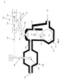
engine assembly 101 with an exemplary embodiment of asystem 100 for controlling engine ignition in accordance with the principles of the present invention, anengine 110, and anexhaust system 150. - As shown, the
engine 110 to which thecontrol system 100 is connected includes apiston 116 disposed in acylinder 112, thepiston 116 being connected to a crankweb 120 by way of a connectingrod 118. Fuel, air, etc. enter thecylinder 112 through thetransfer port 131, to be ignited by theigniter 124 while in thecylinder 112. Exhaust gases, deoxygenated air, etc. exit thecylinder 112 through theexhaust port 132. These components and their operation are described above with respect to Figure 2. - In addition, the
engine 110 defines anintake port 130 therein. As previously noted, theintake port 130 passes an incoming mixture 136 (not shown in Figure 3), i.e. fuel from the fuel system (not shown) into theengine 110. Depending on the particulars of aspecific engine 110, theintake port 130 may also pass air and/or other substances. In addition, as may be seen, in theexemplary engine 110 shown in Figure 3, theintake port 130 not only feeds to thecylinder 112, it also feeds to other components of theengine 110 such as those disposed within thecrank case 113. In certain embodiments this may be desirable, for example in order to deliver a mixture of fuel and oil to the internal components of the engine so as to provide lubrication without a separate lubrication system. However, this is exemplary only, and other arrangements may be equally suitable. - As shown, the
exhaust port 132 of theengine 110 is in communication with anexhaust system 150. Theoutgoing mixture 138 from theengine 110 passes through theexhaust system 150, exiting through theexhaust outlet 154. Exhaust systems per se are well known, and are not further described herein. - The
system 100 itself includes anignition changer 156 for changing the position at which theigniter 124 ignites the mixture of fuel and air in thecylinder 112. - The
ignition changer 156 may take a variety of forms, depending on the particulars of a given embodiment. For example, theignition changer 156 may include an integrated circuit to change the ignition position of thecylinder 112 from its position during normal operation of theengine 110. However, this is exemplary only, andother ignition changers 156 may be equally suitable. - The degree to which the ignition position is changed may vary from embodiment to embodiment. In addition, the degree to which the ignition position is changed may vary depending upon the circumstances, i.e. engine speed or temperature, ambient conditions, fuel mix, etc.
- The
ignition changer 156 may retard the ignition position from the normal operating ignition position for the engine, that is, ignition may occur later in the engine cycle than would otherwise be the case, as may be seen from a comparison of Figures 1 and 2. More particularly, theignition changer 156 may change the ignition position of thecylinder 112 between a warming ignition position similar to that shown in Figure 2 and an operating ignition position similar to that shown in Figure 1. - The
ignition changer 156 may retard the ignition position from the normal operating ignition position for the engine by up to 5 degrees. - The
ignition changer 156 may retard the ignition position from the normal operating ignition position for the engine by at least 5 degrees. - The
ignition changer 156 may retard the ignition position from the normal operating ignition position for the engine by at least 10 degrees. - The
ignition changer 156 may retard the ignition position from the normal operating ignition position for the engine by at least 15 degrees. - The
ignition changer 156 may retard the ignition position from the normal operating ignition position for the engine by at least 20 degrees. - The
ignition changer 156 may retard the ignition position from the normal operating ignition position for the engine by at least 25 degrees. - The
ignition changer 156 may retard the ignition position from the normal operating ignition position for the engine by at least 30 degrees. - The
ignition changer 156 may retard the ignition position from the normal operating ignition position for the engine by at least 35 degrees. - The
ignition changer 156 may retard the ignition position from the normal operating ignition position for the engine by at least 40 degrees. - It is noted that the normal operating ignition position for an
engine 110 depends on the specifics of thatparticular engine 110. Conventionally, some engines may have an ignition position of 10 to 20 degrees before top dead center. Rather than defining the ignition position produced by theignition changer 156 in terms of the difference between that ignition position and the normal operating ignition position, the change in engine position may also be determined in absolute terms rather than relative terms, i.e. as a particular position rather than as a change in position from the normal operating ignition position. - For example, the
ignition changer 156 may retard the ignition position from the normal operating ignition position for the engine to a position of 10 to 20 degrees after top dead center, regardless of the normal operating ignition position. - The
ignition changer 156 is in communication with theigniter 124. As illustrated, theignition changer 156 is connected with theigniter 124 bywire 164. However, this is exemplary only. - The
system 100 also includes anactivator 158 for activating theignition changer 156, so as to change the ignition position of theengine 110. - The
activator 158 may take a variety of forms. In particular, theactivator 158 may be manual, as illustrated in Figure 3, or automatic, as illustrated in Figure 4. - Returning to Figure 3, as shown therein the
activator 158 is a manual activator. That is, theactivator 158 is activated, deactivated, and/or adjusted only by the operator. For example, manual activators may include an on-off switch, wherein an operator manually turns the switch on to change the ignition position, and then manually turns the switch off to return the ignition position to the normal operating position. - However, such an arrangement is exemplary only, and other arrangements of manual activators may be equally suitable.
- As shown in Figure 3, the
activator 158 is in communication with theignition changer 156. As illustrated, theactivator 158 is connected with theignition changer 156 bywire 162. However, this is exemplary only. - The
system 100 may include anexhaust sensor 152 for sensing the condition of theexhaust system 150. - A variety of
exhaust sensors 152 may be suitable for use with the invention. For example, one or more temperature sensors disposed in, on, or near theexhaust system 150 may be used to measure the temperature of the exhaust system. Such sensors may measure the temperature of theexhaust system 150 either directly, i.e. by contact with some portion of theexhaust system 150, indirectly, i.e. by measuring the temperature of exhaust passing through theexhaust system 150. Suitable sensors are known per se, and are not described further herein. -
Exhaust sensors 152 are exemplary only, and embodiments of thesystem 100 without anexhaust sensor 152 may be equally suitable. - In embodiments of the
system 100 that include anexhaust sensor 152, the system may also include adisplay 160 for displaying the condition of theexhaust system 150 as sensed by theexhaust sensor 152 to the vehicle operator. - A variety of
displays 160 may be suitable for use with the invention. For example, a gauge or readout indicating the temperature of theexhaust system 150 may be provided in a location accessible to the vehicle operator, i.e. on the vehicle's control panel. However, such an arrangement is exemplary only.Other displays 160, including but not limited to "idiot lights" indicating that theexhaust system 150 is or is not at a desired temperature, may be equally suitable. - The
display 160 is in communication with theexhaust sensor 152. As illustrated, thedisplay 160 is connected with theexhaust sensor 152 bywire 168. However, this is exemplary only. - As shown in Figure 4, the
activator 158 may automatic. That is, theactivator 158 may be activated, deactivated, and/or adjusted least partially by thesystem 100. - An automatic activator may automatically change the ignition position so that the
exhaust system 150 is always brought to its desired temperature whenever certain conditions are met. - For example, the
system 100 may define two or more "maps" for operation of theengine 110. As used herein, the term "map" refers to a set of operating parameters for theengine 110, including but not limited to ignition position for theengine 110. Thus, thesystem 100 may define a first map used to determine proper operating parameters under various conditions when theengine 110 is being used to move the vehicle, a second map to determine operating parameters when theengine 110 is to be warmed, etc. - In an exemplary arrangement for automatic activation, the
system 100 switches to a warm-up map (if not already using the warm-up map) in response to an instruction sent by the vehicle operator, i.e. when a switch is activated. Theengine 110 then operates according to the warm-up map, i.e. with a retarded ignition position, until the desired temperature for theexhaust system 150 is reached. Thesystem 100 may then return to a normal operation map. Depending on the embodiment, thesystem 100 may override attempts to activate it if the desired temperature has already been reached. For example, activating the switch again may not return thesystem 100 to the warm-up map. - In another exemplary arrangement for automatic activation, the
system 100 also switches to a warm-up map in response to an instruction sent by the vehicle operator. Theengine 110 operates according to the warm-up map, i.e. with a retarded ignition position, until the desired temperature for theexhaust system 150 is reached. Thesystem 100 may then return to a normal operation map. However, thesystem 100 continues to monitor the temperature of theexhaust system 150, and automatically switches back to the warm-up map if the temperature of theexhaust system 150 drops below the desired temperature. Thus in such an embodiment, thesystem 100 would maintain the desired temperature for so long as the switch is activated by cycling between maps. - However, such arrangements are exemplar only. Other
automatic activators 158 may be equally suitable, including but not limited to automatic activators that change the ignition position in response to an instruction sent by the operator, then return the ignition position to normal when a given interval of time has elapsed, or when the vehicle operator puts the vehicle in motion, or that automatically change the map (i.e. the ignition position) whenever the vehicle is started so that theexhaust system 150 is always brought to its desired temperature, may be equally suitable. - In addition, ignition maps are not limited only to parameters that control the temperature of the
exhaust system 150. For example, for certain embodiments it may be desirable to limit engine RPM when the ignition position has been retarded, i.e. during engine warm-up, or when the vehicle transitions from the retarded ignition position to the normal operating ignition position. Thus, a map for changing ignition position may also change the number of ignition sparks per engine revolution, in order to limit engine RPM. Other features and parameters of engine and vehicle operation likewise may be included in maps. - Figure 4 shows an exemplary arrangement wherein the
activator 158 is an automatic activator that automatically changes the ignition position so that theexhaust system 150 is brought to its desired temperature in response to an instruction sent by the vehicle operator. - As with the manual arrangement illustrated in Figure 3, in the automatic arrangement of Figure 4 the
ignition changer 156 are in communication with theigniter 124 and theactivator 158, i.e. bywires exhaust sensor 152 and adisplay 160. However, this arrangement is exemplary only, and other arrangements may be equally suitable. - In addition, a
system 100 with anautomatic activator 158 may include acontroller 172 for controlling theignition changer 156. That is, in the embodiment described herein, when theactivator 158 is activated, thecontroller 172 controls when, how, and how much theignition changer 156 change the ignition position of theengine 110. - As shown, the
controller 172 is in communication with theignition changer 156, i.e. bywire 180 as illustrated. - Likewise, a
system 100 with anautomatic activator 158 may include acomparator 170 for comparing the condition of theexhaust system 150 as sensed by thesensor 152 with other data. The data may be predetermined data, such as a tuned temperature or other target temperature for theexhaust system 150. However, the data may also include data that is not predetermined, such as information regarding ambient conditions, i.e. the outside temperature, and/or other information regarding the vehicle, i.e. the engine speed, etc. - As shown, the
comparator 170 is in communication with thesensor 152 and thecontroller 172, i.e. bywires - For example, in the arrangement illustrated in Figure 4, the
comparator 170 receives signals from theexhaust sensor 152, indicating the temperature of theexhaust system 150. Thecomparator 170 compares the actual temperature of theexhaust system 150 to the desired or tuned temperature ofexhaust system 150, and sends a signal to thecontroller 172. Based on the signal received from thecomparator 170, thecontroller 172 then sends a signal to theignition changer 156 as to when, how, and how much the ignition position of theengine 110 should be changed. -
Suitable comparators 170 andcontrollers 172 include, but are not limited to, integrated circuits. - It is emphasized that this arrangement is exemplary only, and that other arrangements may be equally suitable.
- In particular, at least some of the components illustrated individually in Figure 4 may be integrated into a single unit. For example, in certain embodiments, the
comparator 170,controller 172, and/or theignition changer 156 may be formed as a single integrated circuit. - Furthermore, it is noted that not all of the components illustrated in Figure 4 may be necessary for all embodiments of a
system 100 with anautomatic activator 158. For example, asystem 100 without adisplay 160 may be equally suitable. - As previously noted with regard to Figure 2, the heat emitted by the continuing combustion of the
outgoing mixture 138 causes the temperature of theexhaust system 150 to rise. When thecylinder 112 is being ignited in its operating ignition position, as the temperature of theexhaust system 150 increases towards the tuned temperature of theexhaust system 150, the efficiency of theengine 110 tends to increase. Likewise, the peak power output of theengine 110 tends to increase. That is, the maximum power that theengine 110 can be made to provide increases; the power output of a givenengine 110 will not necessarily be greater at all times when the temperature of theexhaust system 150 is at or near the tuned temperature, since the power output of theengine 110 commonly is variable at the discretion of the vehicle operator. Furthermore, theengine 110 quantity of pollutants produced by theengine 110 tends to decrease as the temperature of theexhaust system 150 increases towards the tuned temperature. - For purposes of simplicity, Figures 2-4 show only one
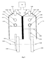
cylinder 112. However, this is exemplary only. Figure 5 shows a portion of anexemplary engine 110 with twocylinders - The
engine 110 includes components in association withcylinder 112A similar to those shown in Figure 2. Thus, theengine 110 includes acylinder head 114A, apiston 116A, a connectingrod 118A, acrank web 120A with an axis ofrotation 122A, anigniter 124A, acylinder wall 126A, atransfer port 131A, and anexhaust port 132A. Likewise, in association withcylinder 112B theengine 110 includes acylinder head 114B, apiston 116B, a connectingrod 118B, acrank web 120B with an axis ofrotation 122B, anigniter 124B, acylinder wall 126B, an atransfer port 131B, and anexhaust port 132B. - For simplicity, not all of the components elsewhere illustrated and described as being present in an engine in accordance with the principles of the present invention, i.e. a crank
case 113, are shown in Figure 5. - In a preferred embodiment, when an
engine 110 has two ormore cylinders 112, theignition changer 156 communicates with the cylinders in at least two groups, so as to ignite the groups independently. - In the arrangement shown in Figure 5,
pistons piston 116A is at bottom dead center, andpiston 116B is at top dead center. - In conventional engines, it is known to ignite all cylinders simultaneously, so that each cylinder is ignited twice during its cycle, and to accept any anomalous combustion or other difficulties that this may produce. Indeed, in some conventional engines the ignition itself is at least partially integrated, i.e. a single ignition coil may be used to operate spark plugs for all of the cylinders.
- However, in order to obtain the greatest advantage from the present invention, it is preferable to ignite the cylinders only at the appropriate ignition position. Thus, as illustrated in Figure 5, the
ignition changer 156 communicates separately with each of theigniters wires cylinders ignition changer 156 to activateigniters exhaust system 150, or is the normal operating ignition position). - Similarly, in
engines 110 having more than twocylinders 112, it may be desirable for theignition changer 156 to change the ignition position of thecylinders 112 in at least two independent groups, so that all of thecylinders 112 can be ignited only at the position desired. In certain embodiments, it may be desirable to ignite eachcylinder 112 independently, and thus it may be desirable that theignition changer 156 be adapted to change the ignition position of eachcylinder 112 independently. - However, this is exemplary only. For some embodiments, not all
cylinders 112 will be ignited independently from one another, and/or not allcylinders 112 will have their ignition positions altered independently. For example, if half of thecylinders 112 of an engine are arranged so that their ignition cycle is offset by 180 degrees from the ignition cycle of the other half of the cylinders 112 (i.e. in the manner thatcylinder 112A is offset fromcylinder 112B in Figure 5), then all of thecylinders 112 can be ignited only at the position desired by igniting thecylinders 112 in only two independent groups. Thus, for such an arrangement, theignition changer 156 might only change the ignition position of thecylinders 112 in two independent groups. - Although Figure 2 shows the ignition cycle of the
engine 110 with the ignition changed from the operating ignition position, and Figures 3 and 4show engine assemblies 101 adapted for so changing the ignition of theengine 110 therein, it is emphasized that theengine control system 100 is not limited only to ignition that is changed from the operating ignition position. Theengine control system 100 also may control theengine 110 so that ignition occurs in the normal operating ignition position, or in other ignition positions. - That is, embodiments of the
engine control system 100 maybe adapted to produce ignition of anengine 110 in both the operating ignition position and one or more changed ignition positions. Theengine control system 100 enables operation of theengine 110 in one or more changed ignition positions for warming theexhaust system 150, but does not preclude operation at other ignition positions. - For example, an exemplary embodiment of the
engine control system 100 may be suited for operating theengine 110 at a first or warming ignition position for warming theexhaust system 150, and also at a second or operating ignition position for normal operation of theengine 110. The engine could be operated initially at the warming ignition position until theexhaust system 150 reaches its tuned temperature, and then could be operated subsequently at the operating ignition position. - Furthermore, an
engine assembly 101 adapted to change its ignition position in accordance with the principles of the present invention is not precluded from otherwise changing its ignition position. For example, the operating ignition position of anengine 110 under the control of anengine control system 100 in accordance with the principles of the present invention may vary even when the ignition position is not being changed to warm theexhaust system 150, i.e. the operating ignition position may vary somewhat depending on engine speed or other conditions. - The above specification, examples and data provide a complete description of the manufacture and use of the composition of the invention. Since many embodiments of the invention can be made without departing from the spirit and scope of the invention, the invention resides in the claims hereinafter appended.
Claims (51)
- A method for improving engine performance, comprising:in an engine assembly comprising an engine with at least one cylinder and a piston disposed within said cylinder, and an exhaust system, said cylinder being in communication with said exhaust system,when a temperature of said exhaust system is lower than a target temperature of said exhaust system, igniting said cylinder at a warming ignition position, wherein in said warming ignition position fuel and air propagate from said cylinder to said exhaust system while undergoing combustion, whereby said temperature of said exhaust system increases towards said target temperature; andigniting said cylinder at an operating ignition position when said temperature of said exhaust system is at least equal to said target temperature, wherein a performance of said engine when said temperature of said exhaust system is at least equal to said target temperature is improved over a performance of said engine when said temperature of said exhaust system is less than said target temperature.
- The method according to claim 1, wherein:said engine is a two-cycle engine.
- The method according to claim 1, further comprising:cycling between said warming ignition position and said operating ignition position to maintain said temperature of said exhaust system at least equal to said target temperature.
- The method according to claim 1, wherein:said warming ignition position is retarded from said operating ignition position.
- The method according to claim 4, wherein:said warming ignition position is retarded from said operating ignition position by up to 5 degrees.
- The method according to claim 4, wherein:said warming ignition position is retarded from said operating ignition position by at least 5 degrees.
- The method according to claim 4, wherein:said warming ignition position is retarded from said operating ignition position by at least 10 degrees.
- The method according to claim 4, wherein:said warming ignition position is retarded from said operating ignition position by at least 15 degrees.
- The method according to claim 4, wherein:said warming ignition position is retarded from said operating ignition position by at least 20 degrees.
- The method according to claim 4, wherein:said warming ignition position is retarded from said operating ignition position by at least 25 degrees.
- The method according to claim 4, wherein:said warming ignition position is retarded from said operating ignition position by at least 30 degrees.
- The method according to claim 4, wherein:said warming ignition position is retarded from said operating ignition position by at least 35 degrees.
- The method according to claim 4, wherein:said warming ignition position is retarded from said operating ignition position by at least 40 degrees.
- The method according to claim 4, wherein:said warming ignition position is 10 to 20 degrees after top dead center.
- The method according to claim 1, further comprising:manually changing between said warming ignition position and said operating ignition position.
- The method according to claim 1, further comprising:measuring said temperature of said exhaust system.
- The method according to claim 16, further comprising:displaying an indication of said temperature of said exhaust system to a vehicle operator.
- The method according to claim 16, further comprising:comparing said exhaust temperature with at least one comparison value using a comparator; andautomatically changing between said warming ignition position and said operating ignition position in response to said comparison of said exhaust temperature with said comparison value.
- The method according to claim 1, wherein said engine comprises at least two cylinders, further comprising igniting at least two of said cylinders independently from one another.
- The method according to claim 1, wherein:a rate at which said engine generates at least one pollutant decreases as said temperature of said exhaust system increases towards said target temperature when said engine is ignited at said operating ignition position.
- The method according to claim 1, wherein:a fuel efficiency of said engine increases as said temperature of said exhaust system increases towards said target temperature when said engine is ignited at said operating ignition position.
- The method according to claim 1, wherein:a peak power output of said engine increases as said temperature of said exhaust system increases towards said target temperature when said engine is ignited at said operating ignition position.
- A method of decreasing output of at least one pollutant from an engine, comprising:in an engine assembly comprising an engine with at least one cylinder and a piston disposed within said cylinder, and an exhaust system, said cylinder being in communication with said exhaust system,when a temperature of said exhaust system is lower than a target temperature of said exhaust system, igniting said cylinder at a warming ignition position, wherein in said warming ignition position fuel and air propagate from said cylinder to said exhaust system while undergoing combustion, whereby said temperature of said exhaust system increases towards said target temperature; andigniting said cylinder at an operating ignition position when said temperature of said exhaust system is at least equal to said target temperature, wherein an output of at least one pollutant when said temperature of said exhaust system is at least equal to said target temperature is less than an output of said at least one pollutant when said temperature of said exhaust system is less than said target temperature.
- A method of increasing fuel efficiency of an engine, comprising:in an engine assembly comprising an engine with at least one cylinder and a piston disposed within said cylinder, and an exhaust system, said cylinder being in communication with said exhaust system,when a temperature of said exhaust system is lower than a target temperature of said exhaust system, igniting said cylinder at a warming ignition position, wherein in said warming ignition position fuel and air propagate from said cylinder to said exhaust system while undergoing combustion, whereby said temperature of said exhaust system increases towards said target temperature; andigniting said cylinder at an operating ignition position when said temperature of said exhaust system is at least equal to said target temperature, wherein a fuel efficiency of said engine when said temperature of said exhaust system is at least equal to said target temperature is greater than a fuel efficiency of said engine when said temperature of said exhaust system is less than said target temperature.
- A method of increasing a power output of an engine, comprising:in an engine assembly comprising an engine with at least one cylinder and a piston disposed within said cylinder, and an exhaust system, said cylinder being in communication with said exhaust system,when a temperature of said exhaust system is lower than a target temperature of said exhaust system, igniting said cylinder at a warming ignition position, wherein in said warming ignition position fuel and air propagate from said cylinder to said exhaust system while undergoing combustion, whereby said temperature of said exhaust system increases towards said target temperature; andigniting said cylinder at an operating ignition position when said temperature of said exhaust system is at least equal to said target temperature, wherein a peak power output of said engine when said temperature of said exhaust system is at least equal to said target temperature is greater than a peak power output of said engine when said temperature of said exhaust system is less than said target temperature.
- An engine control system, comprising:an ignition changer for changing an ignition position of a piston in at least one cylinder of an engine to and from a warming ignition position, wherein in said warming ignition position fuel and air propagate from said cylinder to an exhaust system while undergoing combustion, whereby said temperature of said exhaust system increases, said ignition changer being in communication with an igniter for said engine; andan activator for activating said ignition changer, said activator being in communication with said ignition changer.
- The control system according to claim 26, wherein:said warming ignition position is retarded from an operating ignition position for said engine.
- The control system according to claim 27, wherein:said warming ignition position is retarded from said operating ignition position by up to 5 degrees.
- The control system according to claim 27, wherein:said warming ignition position is retarded from said operating ignition position by at least 5 degrees.
- The control system according to claim 27, wherein:said warming ignition position is retarded from said operating ignition position by at least 10 degrees.
- The control system according to claim 27, wherein:said warming ignition position is retarded from said operating ignition position by at least 15 degrees.
- The control system according to claim 27, wherein:said warming ignition position is retarded from said operating ignition position by at least 20 degrees.
- The control system according to claim 27, wherein:said warming ignition position is retarded from said operating ignition position by at least 25 degrees.
- The control system according to claim 27, wherein:said warming ignition position is retarded from said operating ignition position by at least 30 degrees.
- The control system according to claim 27, wherein:said warming ignition position is retarded from said operating ignition position by at least 35 degrees.
- The control system according to claim 27, wherein:said warming ignition position is retarded from said operating ignition position by at least 40 degrees.
- The control system according to claim 27, wherein:said warming ignition position is 10 to 20 degrees after top dead center.
- The control system according to claim 26, wherein:said activator is a manual activator.
- The control system according to claim 26, further comprising:an exhaust sensor for sensing a temperature of said exhaust system.
- The control system according to claim 39, further comprising:a display for displaying an indication of said temperature of said exhaust system.
- The control system according to claim 39, wherein:said activator is an automatic activator, comprising:a comparator for comparing said temperature of said exhaust system with at least one comparison value, said comparator being in communication with said exhaust sensing means; anda controller for automatically changing to and from said warming ignition position in response to said comparison of said exhaust temperature with said at least one comparison value, so as to automatically reach and maintain a target temperature for said exhaust system, said controller being in communication with said comparator and said ignition changer.
- The control system according to claim 26, wherein:said engine comprises at least two cylinders, each cylinder having a piston disposed therein, and said igniter is adapted to independently ignite at least two of said cylinders; andsaid ignition changer is adapted to change said ignition position of said pistons for said at least two independently ignited cylinders to and from said warming ignition position.
- The control system according to claim 26, wherein:a rate at which said engine generates at least one pollutant when said engine is ignited at an operating ignition position decreases as said temperature of said exhaust system increases towards a target temperature.
- The control system according to claim 26, wherein:a fuel efficiency of said engine when said engine is ignited at an operating ignition position increases as said temperature of said exhaust system increases towards a target temperature.
- The control system according to claim 26, wherein:a power output of said engine when said engine is ignited at an operating ignition position increases as said temperature of said exhaust system increases towards a target temperature.
- A method of operating an engine, comprising:in an engine assembly comprising an engine with at least one cylinder and a piston disposed within said cylinder, and an exhaust system, said cylinder being in communication with said exhaust system,igniting said cylinder at a warming ignition position of said piston, such that fuel and air propagate from said cylinder to said exhaust system while undergoing combustion, whereby a temperature of said exhaust system increases towards a target temperature;subsequently igniting said cylinder at an operating ignition position of said piston different from said warming ignition position.
- The method according to claim 46, wherein:said engine is a two-cycle engine.
- The method according to claim 46, wherein:said cylinder is ignited at said warming ignition position until said temperature of said exhaust system reaches said target temperature.
- The method according to claim 46, further comprising:cycling between said warming ignition position and said operating ignition position to maintain said temperature of said exhaust system at least equal to said target temperature.
- An engine assembly, comprising:an engine, said engine comprising at least one cylinder, a piston disposed within said cylinder, and an igniter for igniting fuel and air within said cylinder;an exhaust system in communication with said cylinder; andan engine control system, comprising:an ignition changer for changing an ignition position of said piston to and from a warming ignition position, such that in said warming ignition position fuel and air propagate from said cylinder to said exhaust system while undergoing combustion, whereby a temperature of said exhaust system increases, said ignition changer being in communication with said igniter; andan activator for activating said ignition changer, said activator being in communication with said ignition changer.
- The method according to claim 50, wherein:said engine is a two-cycle engine.
Applications Claiming Priority (2)
| Application Number | Priority Date | Filing Date | Title |
|---|---|---|---|
| US10/454,861 US6951203B2 (en) | 2003-06-05 | 2003-06-05 | Ignition timing control system |
| US454861 | 2003-06-05 |
Publications (2)
| Publication Number | Publication Date |
|---|---|
| EP1493920A2 true EP1493920A2 (en) | 2005-01-05 |
| EP1493920A3 EP1493920A3 (en) | 2005-04-27 |
Family
ID=33434905
Family Applications (1)
| Application Number | Title | Priority Date | Filing Date |
|---|---|---|---|
| EP04445068A Withdrawn EP1493920A3 (en) | 2003-06-05 | 2004-06-04 | Ignition timing control system |
Country Status (3)
| Country | Link |
|---|---|
| US (1) | US6951203B2 (en) |
| EP (1) | EP1493920A3 (en) |
| CA (1) | CA2469990A1 (en) |
Families Citing this family (6)
| Publication number | Priority date | Publication date | Assignee | Title |
|---|---|---|---|---|
| US8260535B2 (en) | 2007-09-28 | 2012-09-04 | Bombardier Recreational Products Inc. | Load sensor for a vehicle electronic stability system |
| US8647161B2 (en) * | 2009-01-15 | 2014-02-11 | Bombardier Recreational Products Inc. | Method of controlling a personal watercraft |
| CA2962247A1 (en) | 2014-09-23 | 2016-03-31 | Bombardier Recreational Products Inc. | Passenger seat for a vehicle |
| US11913390B2 (en) | 2019-08-30 | 2024-02-27 | Bombardier Recreational Products Inc. | Engine assembly and method for controlling an engine |
| US11905905B2 (en) | 2019-08-30 | 2024-02-20 | Bombardier Recreational Products Inc. | Engine assembly and method for controlling an engine |
| CN114233497B (en) * | 2021-12-14 | 2024-02-20 | 潍柴动力股份有限公司 | Engine control method, system and equipment |
Citations (4)
| Publication number | Priority date | Publication date | Assignee | Title |
|---|---|---|---|---|
| WO1994017293A1 (en) * | 1993-01-25 | 1994-08-04 | Orbital Engine Company (Australia) Pty. Limited | Method of operating an internal combustion engine |
| US5613360A (en) * | 1994-02-18 | 1997-03-25 | Toyota Jidosha Kabushiki Kaisha | Warming up control device for a catalytic converter for an internal combustion engine |
| US5749333A (en) * | 1995-09-08 | 1998-05-12 | Institute Francais Du Petrole | Two-stroke internal-combustion engine depollution process and associated applications |
| US20020152990A1 (en) * | 1999-12-01 | 2002-10-24 | Arctic Cat, Inc. | Two-cycle engine with exhaust temperature-controlled ignition timing |
Family Cites Families (2)
| Publication number | Priority date | Publication date | Assignee | Title |
|---|---|---|---|---|
| JPH03164549A (en) | 1989-11-22 | 1991-07-16 | Fuji Heavy Ind Ltd | Engine control device of two-cycle engine |
| US6237566B1 (en) | 1999-12-01 | 2001-05-29 | Arctic Cat Inc. | Two-cycle engine with exhaust temperature-controlled ignition timing |
-
2003
- 2003-06-05 US US10/454,861 patent/US6951203B2/en not_active Expired - Lifetime
-
2004
- 2004-06-03 CA CA002469990A patent/CA2469990A1/en not_active Abandoned
- 2004-06-04 EP EP04445068A patent/EP1493920A3/en not_active Withdrawn
Patent Citations (4)
| Publication number | Priority date | Publication date | Assignee | Title |
|---|---|---|---|---|
| WO1994017293A1 (en) * | 1993-01-25 | 1994-08-04 | Orbital Engine Company (Australia) Pty. Limited | Method of operating an internal combustion engine |
| US5613360A (en) * | 1994-02-18 | 1997-03-25 | Toyota Jidosha Kabushiki Kaisha | Warming up control device for a catalytic converter for an internal combustion engine |
| US5749333A (en) * | 1995-09-08 | 1998-05-12 | Institute Francais Du Petrole | Two-stroke internal-combustion engine depollution process and associated applications |
| US20020152990A1 (en) * | 1999-12-01 | 2002-10-24 | Arctic Cat, Inc. | Two-cycle engine with exhaust temperature-controlled ignition timing |
Non-Patent Citations (1)
| Title |
|---|
| ERIC GORR: "Basic two stroke tuning" WWW.NH-SCOOTERS.COM, 14 July 2002 (2002-07-14), pages 1-4, XP002315608 INTERNET * |
Also Published As
| Publication number | Publication date |
|---|---|
| US6951203B2 (en) | 2005-10-04 |
| US20040244774A1 (en) | 2004-12-09 |
| CA2469990A1 (en) | 2004-12-05 |
| EP1493920A3 (en) | 2005-04-27 |
Similar Documents
| Publication | Publication Date | Title |
|---|---|---|
| EP1582738B1 (en) | Engine starting system | |
| CN100378316C (en) | Direct fuel injection/spark ignition engine control device | |
| US5881552A (en) | Control system for internal combustion engines and control system for vehicles | |
| US5988137A (en) | Controller of in-cylinder injection spark ignition internal combustion engine | |
| EP1891314B1 (en) | Starting system and method of internal combustion engine | |
| JP5919697B2 (en) | Diesel engine start control device | |
| US5722363A (en) | Cylinder-injection type internal combustion engine and a fuel injection control apparatus therefor | |
| US20050109302A1 (en) | Engine starting system | |
| US6910454B2 (en) | Method of and device for operating a multi-cylinder combustion engine with variable compression ratio | |
| EP1989437A1 (en) | Starting system and method of internal combustion engine | |
| EP1698780A2 (en) | Starting method and system for internal combustion engine | |
| US4725955A (en) | Apparatus for controlling ignition timing in an internal combustion engine | |
| EP0831219A2 (en) | Method for controlling the operation of an internal combustion engine | |
| JP3672805B2 (en) | Pilot ignition gas engine starter | |
| JP4844537B2 (en) | Engine start control device | |
| US6951203B2 (en) | Ignition timing control system | |
| KR0144106B1 (en) | Throttle valve control apparatus for spark ignition two cycle engines | |
| JP4992757B2 (en) | Control method for internal combustion engine | |
| US5730103A (en) | Fuel supply control system for internal combustion engines | |
| JPH09100769A (en) | Ignition timing control method of internal combution engine | |
| JPH06200806A (en) | Air-fuel ratio control device of hydrogen engine | |
| EP1544456A2 (en) | Engine starting system | |
| JPH09310637A (en) | Throttle valve controlling device for infernal combustion engine | |
| JP4442303B2 (en) | Engine starter | |
| JPH08246907A (en) | Valve timing control device for internal combustion engine |
Legal Events
| Date | Code | Title | Description |
|---|---|---|---|
| PUAI | Public reference made under article 153(3) epc to a published international application that has entered the european phase |
Free format text: ORIGINAL CODE: 0009012 |
|
| AK | Designated contracting states |
Kind code of ref document: A2 Designated state(s): AT BE BG CH CY CZ DE DK EE ES FI FR GB GR HU IE IT LI LU MC NL PL PT RO SE SI SK TR |
|
| AX | Request for extension of the european patent |
Extension state: AL HR LT LV MK |
|
| PUAL | Search report despatched |
Free format text: ORIGINAL CODE: 0009013 |
|
| RIC1 | Information provided on ipc code assigned before grant |
Ipc: 7F 02B 61/02 B Ipc: 7F 02P 15/00 B Ipc: 7F 02P 5/02 B Ipc: 7F 02P 5/15 B Ipc: 7F 02P 5/155 B Ipc: 7F 02P 5/04 B Ipc: 7F 02D 37/02 A |
|
| AK | Designated contracting states |
Kind code of ref document: A3 Designated state(s): AT BE BG CH CY CZ DE DK EE ES FI FR GB GR HU IE IT LI LU MC NL PL PT RO SE SI SK TR |
|
| AX | Request for extension of the european patent |
Extension state: AL HR LT LV MK |
|
| 17P | Request for examination filed |
Effective date: 20051020 |
|
| AKX | Designation fees paid |
Designated state(s): FI SE |
|
| REG | Reference to a national code |
Ref country code: DE Ref legal event code: 8566 |
|
| 17Q | First examination report despatched |
Effective date: 20060117 |
|
| STAA | Information on the status of an ep patent application or granted ep patent |
Free format text: STATUS: THE APPLICATION IS DEEMED TO BE WITHDRAWN |
|
| 18D | Application deemed to be withdrawn |
Effective date: 20070322 |