EP1493919A2 - Starter for an internal combustion engine - Google Patents
Starter for an internal combustion engine Download PDFInfo
- Publication number
- EP1493919A2 EP1493919A2 EP04008838A EP04008838A EP1493919A2 EP 1493919 A2 EP1493919 A2 EP 1493919A2 EP 04008838 A EP04008838 A EP 04008838A EP 04008838 A EP04008838 A EP 04008838A EP 1493919 A2 EP1493919 A2 EP 1493919A2
- Authority
- EP
- European Patent Office
- Prior art keywords
- threaded sleeve
- starter
- pinion
- starter according
- shaft
- Prior art date
- Legal status (The legal status is an assumption and is not a legal conclusion. Google has not performed a legal analysis and makes no representation as to the accuracy of the status listed.)
- Withdrawn
Links
Images


Classifications
-
- F—MECHANICAL ENGINEERING; LIGHTING; HEATING; WEAPONS; BLASTING
- F02—COMBUSTION ENGINES; HOT-GAS OR COMBUSTION-PRODUCT ENGINE PLANTS
- F02N—STARTING OF COMBUSTION ENGINES; STARTING AIDS FOR SUCH ENGINES, NOT OTHERWISE PROVIDED FOR
- F02N15/00—Other power-operated starting apparatus; Component parts, details, or accessories, not provided for in, or of interest apart from groups F02N5/00 - F02N13/00
- F02N15/02—Gearing between starting-engines and started engines; Engagement or disengagement thereof
- F02N15/022—Gearing between starting-engines and started engines; Engagement or disengagement thereof the starter comprising an intermediate clutch
- F02N15/023—Gearing between starting-engines and started engines; Engagement or disengagement thereof the starter comprising an intermediate clutch of the overrunning type
-
- F—MECHANICAL ENGINEERING; LIGHTING; HEATING; WEAPONS; BLASTING
- F02—COMBUSTION ENGINES; HOT-GAS OR COMBUSTION-PRODUCT ENGINE PLANTS
- F02N—STARTING OF COMBUSTION ENGINES; STARTING AIDS FOR SUCH ENGINES, NOT OTHERWISE PROVIDED FOR
- F02N15/00—Other power-operated starting apparatus; Component parts, details, or accessories, not provided for in, or of interest apart from groups F02N5/00 - F02N13/00
- F02N15/02—Gearing between starting-engines and started engines; Engagement or disengagement thereof
- F02N15/04—Gearing between starting-engines and started engines; Engagement or disengagement thereof the gearing including disengaging toothed gears
- F02N15/06—Gearing between starting-engines and started engines; Engagement or disengagement thereof the gearing including disengaging toothed gears the toothed gears being moved by axial displacement
Definitions
- the invention relates to a starter for an internal combustion engine according to Preamble of claim 1.
- Such a Screwdriver starter has an electric starter motor, whose drive shaft with a displaceable in the direction of its longitudinal axis Output shaft is in operative connection.
- the drive shaft is at a remote end of the starter motor with a coarse thread provided on the rotatable and displaceable Mit supportiveschaft the output shaft is arranged.
- This entrainment of the Output shaft is over a freewheel with a pinion having Shank connected.
- the starter motor is the Output shaft with the Mitauerschaft, the freewheel and the pinion shaft so vorgespurt that the pinion into a gear wheel of the internal combustion engine meshes.
- This gear is normally locked connected to a crankshaft of the internal combustion engine and is typical formed as external teeth on a flywheel.
- Starter is known from DE 100 16 706 A1.
- This well-known starter motor has a pole tube, which when energized the motor performs a pivoting movement about the motor axis.
- a braking mechanism in Gear set With this Pivoting movement of the pole tube is a braking mechanism in Gear set, which has a braking torque on the driving force of the Output shaft exerts.
- This braking torque causes the Mit supportiveschaft over the coarse thread of the drive shaft of the engine is driven so that the pinion of the starter in the sprocket the internal combustion engine einspurt.
- a generic ertrieb starter for cranking a Internal combustion engine is known from WO 03/008798 A1.
- this known starter is a feed of an output shaft for Traces of a pinion in the ring gear of an internal combustion engine by means of a pole tube arranged on the stator of the starter motor causes, when energized the starter motor pivotal movement around the motor axle experiences.
- a starter for an internal combustion engine has a starter motor and a drivable by this Drive shaft and one in operative connection with the drive shaft, displaceable in the direction of its longitudinal axis output shaft on, which with a pinion shaft with a in a sprocket the Internal combustion engine engageable pinion is coupled.
- a feed the output shaft for meshing the pinion in the sprocket can in particular by means of a provided on the starter of the starter motor Elements take place when energizing the starter motor undergoes a pivoting movement about the motor axis.
- the driver unit at least out two radially in the direction of rotation coupled to each other and axially against each other consists of sliding elements.
- the driver unit Due to the two-part design of the driver unit, the be reduced to accelerating mass when starting. If the starter pinion due to its inertia and frictional forces between Sprocket and starter pinion faces is braked, Nevertheless, the Einspurfeder can be further biased. By The lower mass of the track unit may end up with the pinion Einspurfest very quickly at a tooth gap position in the Sprocket to be accelerated.
- the spring force can act in particular on a drive plate, coupled with a threaded sleeve and axially displaceable on this is.
- the threaded sleeve is preferably on the drive shaft stored and with this by means of a steep thread form-fitting coupled.
- the threaded sleeve and the driver by means of a positive connection in the direction of rotation with each other coupled.
- This positive connection can, for example, in the form an external toothing on the threaded sleeve and a corresponding thereto Internal teeth on the drive plate exist.
- the external teeth of the threaded sleeve and the internal teeth the drive plate can be used in particular as a degree gear teeth be formed, for example. As triangular gears or the like.
- the threaded sleeve can in an advantageous embodiment of a lighter material than steel, for example. Plastic or a composite material be made. In this way their can be accelerated Mass be reduced significantly.
- the pinion shaft via the threaded sleeve is indirectly supported, so that the pinion shaft a defined storage and thus has a perfect concentricity.
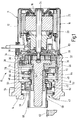
- the illustrated in Figure 1 as a longitudinal section starter 10 has a two-part housing, wherein a first housing part 12 a Starter motor 11 surrounds and a second housing part 14, the drive bearing (not shown) of the starter.
- the starter motor 11 includes in known manner a stator 16 and a rotatable therein mounted rotor 18.
- the stator 16 has a pole tube 20 and therein arranged, designed as permanent magnets stator poles 22.
- the pole tube 20 forms the magnetic return for the stator poles 22, which are arranged concentrically around the rotor 18 around.
- the rotor 18 has a motor shaft 24 which is provided with a laminated core rotatably connected. In not shown grooves of the laminated core one or more rotor windings are introduced.
- the emerging from the starter motor 11 motor shaft 24 is connected to a Transmission, preferably a planetary gear 26 coupled.
- the motor shaft 24 drives a sun gear 28, and the sun gear 28 meshes with planetary gears 30 and 32, which in turn roll off a ring gear 34.
- the ring gear 34 is connected to an intermediate bearing 36 connected.
- the planet gears 30 and 32 are from a Planet carrier 38 held.
- the intermediate storage 36 is stationary and rotatably disposed in the second housing part 14 of the starter 10.
- Of the Planet carrier 38 is rotationally fixed, e.g. integral with a drive shaft 40 connected.
- a threaded sleeve 42 is set on the drive shaft 40.
- the drive shaft 40 and the coaxial with this arranged threaded sleeve 42 are coupled via a coarse thread 44 with each other. That is, at one Inner lateral surface of the threaded sleeve 42 and at a portion an outer circumferential surface of the drive shaft 40 is one each Steep thread toothing applied.
- This the drive shaft 40th and the threaded sleeve 42 connecting coarse thread 44th represents a so-called Einspurgetriebe.
- the threaded sleeve 42nd has an outer toothing at a portion of its outer periphery 46, in which an internal toothing 48 of a drive plate 50 engages.
- the drive plate 50 goes into an outer ring 52 of a freewheel 54 via.
- the outer ring 52 of the freewheel 54 drives via not shown Clamping an inner ring 56, which with a pinion shaft 58th connected is.
- the pinion shaft 58 At his from the second housing part 14 of the starter 10 pointed end is the pinion shaft 58 with a pinion 60 provided with spur toothing.
- the pinion shaft 58 experiences upon rotation of the motor shaft 24 by the helical thread 44 running Einspurgetriebe between the drive shaft 40 and the output shaft 43 a feed, so that the pinion 60 in a sprocket 62 einspurt an internal combustion engine, not shown.
- Einspurvorgang and the Ausspurvorgang will be in the following described in more detail.
- the drive shaft 40 is within the threaded sleeve 42, drive plate 50 with freewheel 54 and pinion shaft 58 formed output shaft 43 rotatably mounted (not shown). Furthermore, it is the output shaft 43 preferably in the second housing part 14th via at least one bearing (not shown) about its longitudinal axis rotatably mounted.
- the pole tube 20 of the starter motor 11 is about the axis of rotation of the motor shaft 24 pivotable at a certain angle (about 10 ° to 30 °) stored.
- On the pole tube 20 are one or more - for example three arms 64 extending into the second housing part 14, in which the transmission is for driving the output shaft 43, extend into it.
- Each arm 64 of the pole tube 20 is through a Recess 66 on the outer circumference of the second housing part 14th rotatably arranged intermediate bearing 36 out. Every recess 66 on the intermediate bearing 36 or on a brush holder 83 has two Stops 68 and 70 on which the pivoting movement of the pole tube Limit 20 around the motor axis.
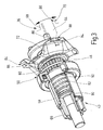
- a recess 66 on Intermediate bearing 36 with its two stops 68 and 70 and a guided therein arm 64 of the pole tube 20 shows the perspective Representation of a section of the starter 10 in the figure 3.
- the starter motor acts on the pole tube 20 due of prevailing between the rotor 18 and stator 16 electromagnetic Forces a torque, causing the pole tube 20 in a certain direction, e.g. clockwise around the motor axis is turned. It is a spring element not shown in the drawing provided, which this torque of the pole tube 20th counteracts.
- the spring element can eg. At the intermediate storage 36th be installed. The height of the torque acting on the pole tube 20 depends on the strength of the current flowing through the rotor winding Power off.
- a substantially radially projecting disc 72 mounted so that they are around the Axle of the threaded sleeve 42 of the output shaft is rotatable. Against one axial displacement against the feed direction of the threaded sleeve 42, the disc 72 is secured. This is done, for example, by means of an on the threaded sleeve 42 patch retaining ring 74, on which the disc 72 is present. The retaining ring 74 is by means of a locking ring 76th against an axial displacement against the feed direction of the Output shaft 43 secured.
- a Support ring 78 placed on the threaded sleeve 42, of a on the outer ring 52 of the freewheel 54 supporting spring 80 against the Disk 72 is pressed.
- This spring is due to its function when meshing the pinion 60 in the ring gear 62 below designated as Einspurfeder 80.
- a further spring 82 is inserted, which as the Einspurfeder 80 a pressure on the disc 72 and thus on the output shaft 43 against the feed direction of the output shaft 43 exercises.
- This second spring is hereinafter referred to as Ausspurfeder 82 indicates because they are out of the pinion 60 from the ring gear 62 supported.
- FIG. 2 illustrates in a semi-longitudinal section, the arrangement of central assembly for transmitting the rotational movement of the starter motor 11 on the pinion shaft 58 and the generation of the Traces of the pinion 60 in the ring gear 62 necessary feed movement.
- the coarse thread 44 of the drive shaft 40 via which a rotary and feed movement on the threaded sleeve 42 is transferable.
- the threaded sleeve 42 on its inner circumference with a coarse thread 44 of the drive shaft 40 corresponding coarse thread on.
- On the outer circumference is at the starter motor 11 facing Side of the threaded sleeve 42 an external toothing 46 is provided, with the corresponding internal teeth 48 of the drive plate 50 corresponds.
- threaded sleeve 42 and drive plate 50 independently from each other in the axial direction against each other be moved.
- FIG. 3 shows a perspective partial sectional view of the assembly corresponding to Figure 2, in particular, the rotation the disc 72 by means of engaging in second recesses 84 Arms 64 is illustrated.
- a slimmer end section each Arms 64 has chamfers, which by sliding on the stops 86 and 88 of each second recess 84 for a axial feed of the disc 72 can provide in Einspurides.
- the pinion shaft 58 with the thereto End-mounted pinion 60 in Einspurettivoten in Einspurides i. in the direction to the ring gear (not shown) of the internal combustion engine shifts.
- the Ausspureder 82 disposed within the pinion shaft 58 and is supported between a stop disc 90 at the axial end of the Pinion 60 and a radial support collar 92 of the threaded sleeve 42nd from.
- the spring force of the Ausspurfeder 82 is thus the spring force of Einspurfeder the 80 opposite and ensures a trace of the Pinion 60, as soon as the axial force component through the axially displaced Disc 72 is eliminated. This is the case when the starter motor 11 is no longer energized, the pole tube 20 in its initial position turns back and the arms 64 again in one of the arrow directions Swing back.
- the explained with reference to Figures 1 to 3 way to apply the axial feed force on the output shaft provides only one of several possible variants. This variant is thus not restrictive to understand.
- the axial force component can optionally also by means of a separately operable by the drive motor Actuator done, for example. By means of an electromagnet, the via suitable actuating arms causes a feed of the output shaft.
- FIG. 4 illustrates in particular the axial Displacement of the provided with the external teeth 46 threaded sleeve 42 in the axial direction in the with the internal teeth 48th provided drive plate 50.
- the teeth are shown in the Embodiment designed as a straight toothing.
- Figure 6 illustrates the design of the threaded sleeve 42, the at the the support collar 92 side facing away from the toothed outer circumference a recess 94 for receiving the locking ring 76 to the axial Fixing the retaining ring 74 and the disc 72 has.
- One to External teeth 46 directed stop surface 96 on the support collar 92nd at the same time forms an axial stop, the displaceability the threaded sleeve 42 is limited against the drive plate 50.
- the drive plate 50 can in particular be extruded from a metal become.
- the threaded sleeve 42 may, for example. Metal or consist of a suitable composite material.
- the disc 72 When energizing the starter motor 11, the disc 72 is in shifted axial direction, which also the pinion shaft 58 in the direction is moved to the ring gear 62.
- This axial movement of the pinion shaft 58 is determined by the inertia of the Einspurtechnik and a sliding of the threaded sleeve 42 via the coarse thread 44 due the rotational movement of the motor shaft 24 is supported. Support takes place at the beginning of the Einspurvorgangs only in weak Extent.
- the two-part driver according to the invention consisting of threaded sleeve 42 and drive plate 50 allows it now in an advantageous Way to further compress the lane of the 80, when a tooth-on-tooth position of the pinion 60 on the Toothed ring 62 prevents complete meshing first. Due to the friction between the end faces of the pinion 60 and the Sprocket 62, the rotational movement of the starter pinion 60 first braked.
- the already rotating starter motor 11 provides through the coarse thread for an axial displacement of the threaded sleeve 42 in a rectilinear Form fit axially within the drive plate 50, whereby at the same time the Einspurfeder 80 are biased further can. If a tooth gap is subsequently found, then the Einspurfeder 80 the starter pinion 60 in the ring gear 62 into it. Due to the additional frictional torque between the tooth flanks within the possible bolting path the entire pick-up unit by the rotating starter motor 11 via the coarse thread 44 screwed into the ring gear 62, even if already the maximum Displacement of the disc 72 and thus the threaded sleeve 42 against the drive plate 50 is reached.
- the division according to the invention of the Einspuriser allows a reduction in the acceleration of the starter motor 11 to be accelerated Mass, allowing the pinion 60 as possible when cranking quickly accelerated to the next tooth gap of the ring gear 62 is turned on and the internal combustion engine successfully can be.
- a sufficiently high biasing force of the Einspurfeder 80 and a small mass to be accelerated can by a Separation and axial displacement with simultaneous radial Positive connection of Einspuriser in a threaded sleeve and a drive plate be achieved.
- Rotational movement of the pole tube 20 can be used to at a Tooth-on-tooth position to further bias the Einspurfeder 80.
- the mass to be accelerated can be reduced.
- the each other sliding parts threaded sleeve 42 and drive plate 50th are in so-called. Free-launching starters inside the starter housing and are thus secured against ingress of dirt. If the starter motor 11 is already rotating, the starter pinion 60 but on Reason for its inertia and friction between sprocket and starter pinion faces is braked, can now the starter motor 11 via the coarse thread 44 of the drive shaft 40 and the threaded sleeve 42 move this axially further against the drive plate 50 and biasing the lashing spring 80 further therewith.
- the now lower Mass of the Einauge unit can at the end of the screw very accelerated quickly in toothed position in the ring gear 62 become.
- the driver can be very be built flat and in an advantageous manner, for example, in one operation be pressed together with the internal toothing 48.
- the subsequent machining effort for final shaping is relatively low.
- a broaching process can be omitted, since the drive plate 50 has no coarse thread more, because this was displaced into the threaded sleeve 42.
- the threaded sleeve 42 may depending on the strength requirements Steel, made of plastic or of a composite material become.
Abstract
Description
Die Erfindung betrifft einen Starter für eine Brennkraftmaschine gemäß Oberbegriff des Patentanspruchs 1.The invention relates to a starter for an internal combustion engine according to Preamble of claim 1.
Als elektrische Starter zum Andrehen von Brennkraftmaschinen werden oftmals sogenannte Schraubtrieb-Starter eingesetzt. Ein derartiger Schraubtrieb-Starter weist einen elektrischen Startermotor auf, dessen Antriebswelle mit einer in Richtung ihrer Längsachse verschiebbaren Abtriebswelle in Wirkverbindung steht. Die Antriebswelle ist an einem dem Startermotor entfernten Ende mit einem Steilgewinde versehen, auf dem dreh- und verschiebbar ein Mitnehmerschaft der Abtriebswelle angeordnet ist. Dieser Mitnehmerschaft der Abtriebswelle ist über einen Freilauf mit einem das Ritzel aufweisenden Schaft verbunden. Durch Einschalten des Startermotors wird die Abtriebswelle mit dem Mitnehmerschaft, dem Freilauf und dem Ritzelschaft so vorgespurt, dass das Ritzel in ein Zahnrad der Brennkraftmaschine einspurt. Dieses Zahnrad ist normalerweise drehfest mit einer Kurbelwelle der Brennkraftmaschine verbunden und ist typischerweise als Außenverzahnung an einer Schwungscheibe ausgebildet.As electric starter for cranking internal combustion engines often used so-called Schraubtrieb starter. Such a Screwdriver starter has an electric starter motor, whose drive shaft with a displaceable in the direction of its longitudinal axis Output shaft is in operative connection. The drive shaft is at a remote end of the starter motor with a coarse thread provided on the rotatable and displaceable Mitnehmerschaft the output shaft is arranged. This entrainment of the Output shaft is over a freewheel with a pinion having Shank connected. By switching on the starter motor is the Output shaft with the Mitnehmerschaft, the freewheel and the pinion shaft so vorgespurt that the pinion into a gear wheel of the internal combustion engine meshes. This gear is normally locked connected to a crankshaft of the internal combustion engine and is typical formed as external teeth on a flywheel.
Ein nach dem sogenannten Brems-Schraubtrieb-Prinzip arbeitender Starter ist aus der DE 100 16 706 A1 bekannt. Dieser bekannte Startermotor weist ein Polrohr auf, das bei einer Bestromung des Motors eine Schwenkbewegung um die Motorachse durchführt. Mit dieser Schwenkbewegung des Polrohrs wird ein Bremsmechanismus in Gang gesetzt, der ein Bremsmoment auf den Mitnehmerschaft der Abtriebswelle ausübt. Dieses Bremsmoment bewirkt, dass der Mitnehmerschaft über das Steilgewinde von der Antriebswelle des Motors vorgetrieben wird, so dass das Ritzel des Starters in den Zahnkranz der Brennkraftmaschine einspurt.A working according to the so-called brake screwdriving principle Starter is known from DE 100 16 706 A1. This well-known starter motor has a pole tube, which when energized the motor performs a pivoting movement about the motor axis. With this Pivoting movement of the pole tube is a braking mechanism in Gear set, which has a braking torque on the driving force of the Output shaft exerts. This braking torque causes the Mitnehmerschaft over the coarse thread of the drive shaft of the engine is driven so that the pinion of the starter in the sprocket the internal combustion engine einspurt.
Ein gattungsgemäßer Schraubtrieb-Starter zum Andrehen einer Brennkraftmaschine ist aus der WO 03/008798 A1 bekannt. Bei diesem bekannten Starter wird ein Vorschub einer Abtriebswelle zum Einspuren eines Ritzels in den Zahnkranz einer Brennkraftmaschine mittels eines am Stator des Startermotors angeordneten Polrohrs bewirkt, das bei einer Bestromung des Startermotors eine Schwenkbewegung um die Motorachse erfährt. Dabei sind Einrichtungen vorgesehen, welche die Schwenkbewegung des Polrohrs direkt in eine auf die Abtriebswelle wirkende Axialbewegung umsetzen.A generic Schraubtrieb starter for cranking a Internal combustion engine is known from WO 03/008798 A1. In this known starter is a feed of an output shaft for Traces of a pinion in the ring gear of an internal combustion engine by means of a pole tube arranged on the stator of the starter motor causes, when energized the starter motor pivotal movement around the motor axle experiences. There are facilities provided which the pivoting movement of the pole tube directly into a Convert axial movement acting on the output shaft.
Ein Starter für eine Brennkraftmaschine gemäß vorliegender Erfindung weist einen Startermotor sowie eine von diesem antreibbare Antriebswelle und eine mit der Antriebswelle in Wirkverbindung stehende, in Richtung ihrer Längsachse verschiebbare Abtriebswelle auf, welche mit einer Ritzelwelle mit einem in einen Zahnkranz der Brennkraftmaschine einspurbaren Ritzel gekoppelt ist. Ein Vorschub der Abtriebswelle zum Einspuren des Ritzels in den Zahnkranz kann insbesondere mittels eines am Starter des Startermotors vorgesehenen Elements erfolgen, das bei einer Bestromung des Startermotors eine Schwenkbewegung um die Motorachse erfährt. Diese Schwenkbewegung ist mittels einer auf der Antriebswelle gelagerten, um diese drehbare und axial in Vorschubrichtung gegen eine Federkraft abgestützte Scheibe in eine auf die Ritzelwelle wirkende Axialbewegung umsetzbar. A starter for an internal combustion engine according to the present invention has a starter motor and a drivable by this Drive shaft and one in operative connection with the drive shaft, displaceable in the direction of its longitudinal axis output shaft on, which with a pinion shaft with a in a sprocket the Internal combustion engine engageable pinion is coupled. A feed the output shaft for meshing the pinion in the sprocket can in particular by means of a provided on the starter of the starter motor Elements take place when energizing the starter motor undergoes a pivoting movement about the motor axis. These Pivoting movement is by means of a mounted on the drive shaft, around this rotatable and axially in the feed direction against a spring force supported disc in a force acting on the pinion shaft axial movement implemented.
Alternativ hierzu gibt es jedoch auch andere Möglichkeiten zum Aufbringen der axialen Vorschubkraft auf die Abtriebswelle. Erfindungsgemäß ist vorgesehen, dass die Mitnehmereinheit zumindest aus zwei radial in Drehrichtung miteinander gekoppelten und axial gegeneinander verschiebbaren Elementen besteht.Alternatively, however, there are other ways to apply the axial feed force on the output shaft. According to the invention is provided that the driver unit at least out two radially in the direction of rotation coupled to each other and axially against each other consists of sliding elements.
Durch die zweiteilige Ausgestaltung der Mitnehmereinheit kann die beim Starten zu beschleunigende Masse reduziert werden. Wenn das Starterritzel aufgrund seiner Trägheit und Reibungskräften zwischen Zahnkranz- und Starterritzelstirnflächen abgebremst wird, kann dennoch die Einspurfeder weiter vorgespannt werden. Durch die geringere Masse der Einspureinheit kann das Ritzel am Ende der Einspurbewegung sehr schnell bei einer Zahnlückenstellung in den Zahnkranz beschleunigt werden.Due to the two-part design of the driver unit, the be reduced to accelerating mass when starting. If the starter pinion due to its inertia and frictional forces between Sprocket and starter pinion faces is braked, Nevertheless, the Einspurfeder can be further biased. By The lower mass of the track unit may end up with the pinion Einspurbewegung very quickly at a tooth gap position in the Sprocket to be accelerated.
Die Federkraft kann insbesondere auf eine Mitnehmerscheibe wirken, die mit einer Gewindehülse gekoppelt und auf dieser axial verschiebbar ist. Die Gewindehülse ist vorzugsweise auf der Antriebswelle gelagert und mit dieser mittels eines Steilgewindes formschlüssig gekoppelt. Vorzugsweise sind die Gewindehülse und die Mitnehmer mittels einer Formschlussverbindung in Drehrichtung miteinander gekoppelt. Diese Formschlussverbindung kann bspw. in Form einer Außenverzahnung an der Gewindehülse und einer damit korrespondierenden Innenverzahnung an der Mitnehmerscheibe bestehen.The spring force can act in particular on a drive plate, coupled with a threaded sleeve and axially displaceable on this is. The threaded sleeve is preferably on the drive shaft stored and with this by means of a steep thread form-fitting coupled. Preferably, the threaded sleeve and the driver by means of a positive connection in the direction of rotation with each other coupled. This positive connection can, for example, in the form an external toothing on the threaded sleeve and a corresponding thereto Internal teeth on the drive plate exist.
Die Außenverzahnung der Gewindehülse und die Innenverzahnung der Mitnehmerscheibe können insbesondere als Gradverzahnungen ausgebildet sein, bspw. als Dreiecksverzahnungen oder dgl.The external teeth of the threaded sleeve and the internal teeth the drive plate can be used in particular as a degree gear teeth be formed, for example. As triangular gears or the like.
Die Gewindehülse kann in vorteilhafter Ausgestaltung aus einem leichteren Werkstoff als Stahl bspw. aus Kunststoff bzw. einem Verbundwerkstoff gefertigt sein. Auf diese Weise kann ihre zu beschleunigende Masse deutlich reduziert werden.The threaded sleeve can in an advantageous embodiment of a lighter material than steel, for example. Plastic or a composite material be made. In this way their can be accelerated Mass be reduced significantly.
Vorzugsweise ist die Ritzelwelle über die Gewindehülse mittelbar abgestützt, so dass die Ritzelwelle eine definierte Lagerung und damit einen einwandfreien Rundlauf aufweist.Preferably, the pinion shaft via the threaded sleeve is indirectly supported, so that the pinion shaft a defined storage and thus has a perfect concentricity.
Weitere vorteilhafte Ausgestaltungen der Erfindung ergeben sich aus den übrigen, in den abhängigen Ansprüchen genannten Merkmalen.Further advantageous embodiments of the invention will become apparent the rest, mentioned in the dependent claims features.
Die Erfindung wird nachfolgend in bevorzugten Ausführungsbeispielen anhand der zugehörigen Zeichnungen näher erläutert. Dabei zeigt:
- Figur 1
- einen schematischen Längsschnitt eines erfindungsgemäßen Starters in einer ersten Variante,
- Figur 2
- einen schematischen Halbschnitt eines Teils des Starters gemäß Figur 1,
- Figur 3
- einen perspektivischen Teilschnitt des Starters in einer modifizierten Variante,
- Figur 4
- eine Mitnehmerscheibe sowie eine damit koppelbare Gewindehülse des Starters,
- Figur 5
- die Mitnehmerscheibe gemäß Figur 4 in einer gedrehten Ansicht und
- Figur 6
- die Gewindehülse gemäß Figur 4 in vergrößerter Perspektivdarstellung.
- FIG. 1
- 3 shows a schematic longitudinal section of a starter according to the invention in a first variant,
- FIG. 2
- 1 is a schematic half section of a part of the starter according to FIG. 1,
- FIG. 3
- a perspective partial section of the starter in a modified variant,
- FIG. 4
- a drive plate and a thus coupled threaded sleeve of the starter,
- FIG. 5
- the drive plate according to Figure 4 in a rotated view and
- FIG. 6
- the threaded sleeve according to Figure 4 in an enlarged perspective view.
Der in Figur 1 als Längsschnitt dargestellte Starter 10 weist ein
zweiteiliges Gehäuse auf, wobei ein erstes Gehäuseteil 12 einen
Startermotor 11 umgibt und ein zweites Gehäuseteil 14 das Antriebslager
(nicht dargestellt) des Starters aufnimmt. Der Startermotor 11
umfasst in bekannter Weise einen Stator 16 und einen darin drehbar
gelagerten Rotor 18. Der Stator 16 weist ein Polrohr 20 und darin
angeordnete, als Permanentmagnete ausgeführte Statorpole 22 auf.
Das Polrohr 20 bildet den magnetischen Rückschluss für die Statorpole
22, die konzentrisch um den Rotor 18 herum angeordnet sind.
Der Rotor 18 weist eine Motorwelle 24 auf, die mit einem Blechpaket
drehfest verbunden ist. In nicht dargestellten Nuten des Blechpakets
sind ein oder mehrere Rotorwicklungen eingebracht.The illustrated in Figure 1 as a
Die aus dem Startermotor 11 austretende Motorwelle 24 ist mit einem
Getriebe, vorzugsweise einem Planetengetriebe 26 gekoppelt.
Die Motorwelle 24 treibt dabei ein Sonnenrad 28 an, und das Sonnenrad
28 kämmt mit Planetenrädern 30 und 32, die wiederum in
einem Hohlrad 34 abwälzen. Das Hohlrad 34 ist mit einem Zwischenlager
36 verbunden. Die Planetenräder 30 und 32 werden von einem
Planetenträger 38 gehalten. Das Zwischenlager 36 ist ortsfest und
drehfest im zweiten Gehäuseteil 14 des Starters 10 angeordnet. Der
Planetenträger 38 ist drehfest, z.B. einstückig mit einer Antriebswelle
40 verbunden.The emerging from the
Auf die Antriebswelle 40 ist eine Gewindehülse 42 gesetzt. Die Antriebswelle
40 und die koaxial zu dieser angeordnete Gewindehülse
42 sind über ein Steilgewinde 44 miteinander gekoppelt. D.h., an einer
Innenmantelfläche der Gewindehülse 42 sowie an einem Abschnitt
einer Außenmantelfläche der Antriebswelle 40 ist jeweils eine
Steilgewindeverzahnung aufgebracht. Dieses die Antriebswelle 40
und die Gewindehülse 42 miteinander verbindende Steilgewinde 44
stellt ein sogenanntes Einspurgetriebe dar. Die Gewindehülse 42
weist an einem Abschnitt ihres äußeren Umfangs eine Außenverzahnung
46 auf, in die eine Innenverzahnung 48 einer Mitnehmerscheibe
50 eingreift. Die Mitnehmerscheibe 50 geht in einen Außenring
52 eines Freilaufs 54 über.On the
Der Außenring 52 des Freilaufs 54 treibt über nicht dargestellte
Klemmkörper einen Innenring 56 an, der mit einem Ritzelschaft 58
verbunden ist. An seinem aus dem zweiten Gehäuseteil 14 des Starters
10 herausweisenden Ende ist der Ritzelschaft 58 mit einem Ritzel
60 mit Geradverzahnung versehen. Der Ritzelschaft 58 erfährt
bei Drehen der Motorwelle 24 durch das als Steilgewinde 44 ausgeführte
Einspurgetriebe zwischen der Antriebswelle 40 und der Abtriebswelle
43 einen Vorschub, so dass das Ritzel 60 in einen Zahnkranz
62 einer nicht dargestellten Brennkraftmaschine einspurt. Der
Einspurvorgang und der Ausspurvorgang werden im Folgenden noch
detaillierter beschrieben.The
Die Antriebswelle 40 ist innerhalb der aus Gewindehülse 42, Mitnehmerscheibe
50 mit Freilauf 54 und Ritzelschaft 58 gebildeten Abtriebswelle
43 drehbar gelagert (nicht dargestellt). Des weiteren ist
die Abtriebswelle 43 vorzugsweise in dem zweiten Gehäuseteil 14
über wenigstens ein Lager (nicht dargestellt) um seine Längsachse
drehbar gelagert.The
Das Polrohr 20 des Startermotors 11 ist um die Drehachse der Motorwelle
24 um einen gewissen Winkel (ca. 10° bis 30°) schwenkbar
gelagert. An dem Polrohr 20 befinden sich ein oder mehrere - beispielsweise
drei - Arme 64, die sich in den zweiten Gehäuseteil 14,
in dem sich das Getriebe für den Antrieb der Abtriebswelle 43 befindet,
hinein erstrecken. Jeder Arm 64 des Polrohrs 20 ist durch eine
Aussparung 66 am Außenumfang des im zweiten Gehäuseteil 14
drehfest angeordneten Zwischenlagers 36 geführt. Jede Aussparung
66 am Zwischenlager 36 oder an einem Bürstenhalter 83 weist zwei
Anschläge 68 und 70 auf, welche die Schwenkbewegung des Polrohrs
20 um die Motorachse begrenzen. Eine Aussparung 66 am
Zwischenlager 36 mit ihren beiden Anschlägen 68 und 70 und einem
darin geführten Arm 64 des Polrohrs 20 zeigt die perspektivische
Darstellung eines Ausschnitts des Starters 10 in der Figur 3.The
Sobald der Startermotor bestromt wird, wirkt auf das Polrohr 20 aufgrund
von zwischen Rotor 18 und Stator 16 herrschenden elektromagnetischen
Kräften ein Drehmoment, wodurch das Polrohr 20 in
eine bestimmte Richtung, z.B. im Uhrzeigersinn um die Motorachse
gedreht wird. Es ist ein in der Zeichnung nicht dargestelltes Federelement
vorgesehen, welches diesem Drehmoment des Polrohrs 20
entgegenwirkt. Das Federelement kann bspw. am Zwischenlager 36
eingebaut sein. Die Höhe des auf das Polrohr 20 wirkenden Drehmoments
hängt von der Stärke des durch die Rotorwicklung fließenden
Stromes ab.As soon as the starter motor is energized, acts on the
Auf der Gewindehülse 42 der Abtriebswelle 43 ist eine im Wesentlichen
radial abstehende Scheibe 72 so gelagert, dass sie um die
Achse der Gewindehülse 42 der Abtriebswelle drehbar ist. Gegen ein
axiales Verschieben gegen die Vorschubrichtung der Gewindehülse
42 ist die Scheibe 72 gesichert. Dies erfolgt bspw. mittels eines auf
der Gewindehülse 42 aufgesetzten Halterings 74, an dem die Scheibe
72 anliegt. Der Haltering 74 ist mittels eines Sicherungsrings 76
gegen eine axiale Verschiebung entgegen die Vorschubrichtung der
Abtriebswelle 43 gesichert.On the threaded
Bei einer Verdrehung des Polrohrs 20 wird auch die Scheibe 72 verdreht
und gleichzeitig in axialer Richtung verschoben, wie dies anhand
der Figur 3 noch näher erläutert wird.With a rotation of the
Auf der den Freilauf 54 zugewandten Seite der Scheibe 72 ist ein
Stützring 78 auf die Gewindehülse 42 aufgesetzt, der von einer sich
am Außenring 52 des Freilaufs 54 abstützenden Feder 80 gegen die
Scheibe 72 gedrückt wird. Diese Feder wird wegen ihrer Funktion
beim Einspuren des Ritzels 60 in den Zahnkranz 62 im Folgenden
als Einspurfeder 80 bezeichnet. Zwischen der Scheibe 72 und dem
zweiten Gehäuseteil 14 ist eine weitere Feder 82 eingesetzt, welche
wie die Einspurfeder 80 einen Druck auf die Scheibe 72 und damit
auf die Abtriebswelle 43 entgegen der Vorschubrichtung der Abtriebswelle
43 ausübt. Diese zweite Feder wird nachfolgend als Ausspurfeder
82 bezeichnet, weil sie das Ausspuren des Ritzels 60 aus
dem Zahnkranz 62 unterstützt. Die zuvor erwähnten Einspur- bzw.
Ausspurkräfte können auch mit anderen Federelementen, die an anderen
Stellen im Starter 10 angeordnet sind als in den Figuren dargestellt,
aufgebracht werden. Bspw. kann die Ausspurfeder 82 auch
zwischen dem Ritzelschaft 58 der axial verschiebbaren Abtriebswelle
43 und dem ritzelseitigen Ende der axial fixierten Antriebswelle 40
eingesetzt sein, wie dies bei der alternativen Variante entsprechend
den Figuren 2 und 3 gezeigt ist.On the
Figur 2 verdeutlicht in einem Halblängsschnitt die Anordnung der
zentralen Baugruppe zur Übertragung der Drehbewegung des Startermotors
11 auf den Ritzelschaft 58 sowie die Erzeugung der zum
Einspuren des Ritzels 60 in den Zahnkranz 62 notwendigen Vorschubbewegung.
Deutlich erkennbar ist hier insbesondere das Steilgewinde
44 der Antriebswelle 40, über das eine Dreh- und Vorschubbewegung
auf die Gewindehülse 42 übertragbar ist. Hierzu
weist die Gewindehülse 42 an ihrem Innenumfang ein mit dem Steilgewinde
44 der Antriebswelle 40 korrespondierendes Steilgewinde
auf. Am Außenumfang ist an der dem Startermotor 11 zugewandten
Seite der Gewindehülse 42 eine Außenverzahnung 46 vorgesehen,
die mit der entsprechenden Innenverzahnung 48 der Mitnehmerscheibe
50 korrespondiert. Somit können Gewindehülse 42 und Mitnehmerscheibe
50 unabhängig voneinander in axialer Richtung gegeneinander
verschoben werden.Figure 2 illustrates in a semi-longitudinal section, the arrangement of
central assembly for transmitting the rotational movement of the
Die Verzahnungen 46, 48 sorgen jedoch jederzeit für eine formschlüssige
Drehverbindung zur Übertragung des notwendigen Drehmoments
auf die Abtriebswelle 43 und den Ritzelschaft 58. Weiterhin
ist der im Außenring 52 der Mitnehmerscheibe 50 angeordnete Freilauf
54 erkennbar, der für eine Drehmomentübertragung in nur einer
Drehrichtung sorgt und den Ritzelschaft 58 in der entgegengesetzten
Drehrichtung frei drehen lässt. Hierdurch kann sichergestellt werden,
dass eine bereits laufende Brennkraftmaschine nicht zu einer Beschädigung
des Starters 10 führen kann, sondern dass der Ritzelschaft
58 bei noch im Zahnkranz 62 eingespurtem Ritzel 60 frei drehen
kann. In der gezeigten Darstellung der Figur 2 ist auch die axiale
Kraftübertragung von der Scheibe 72 über die Einspurfeder 80 auf
die Mitnehmerscheibe 50 verdeutlicht.However, the
Figur 3 zeigt eine perspektivische Teilschnittdarstellung der Baugruppe
entsprechend Figur 2, bei der insbesondere die Verdrehung
der Scheibe 72 mit Hilfe des in zweite Aussparungen 84 eingreifenden
Arme 64 verdeutlicht ist. Ein schlankerer Endabschnitt jedes
Arms 64 weist Abschrägungen auf, die durch Gleitbewegungen an
den Anschlägen 86 und 88 jeder zweiten Aussparung 84 für einen
axialen Vorschub der Scheibe 72 in Einspurrichtung sorgen können.
Bei einem axialen Vorschub der Scheibe 72 wird über die Einspurfeder
80 eine axiale Kraft auf die Mitnehmerscheibe 50 ausgeübt, die
ihrerseits über den Freilauf 54 den Ritzelschaft 58 mit dem daran
endseitig angebrachten Ritzel 60 in Einspurrichtung, d.h. in Richtung
zum Zahnkranz (nicht dargestellt) der Brennkraftmaschine verschiebt.FIG. 3 shows a perspective partial sectional view of the assembly
corresponding to Figure 2, in particular, the rotation
the
Bei der in der Figur 3 gezeigten Variante der Einspureinrichtung ist
die Ausspurfeder 82 innerhalb des Ritzelschafts 58 angeordnet und
stützt sich zwischen einer Anschlagscheibe 90 am axialen Ende des
Ritzels 60 und einem radialen Stützbund 92 der Gewindehülse 42
ab. Die Federkraft der Ausspurfeder 82 ist somit der Federkraft der
Einspurfeder 80 entgegengesetzt und sorgt für ein Ausspuren des
Ritzels 60, sobald die axiale Kraftkomponente durch die axial verschobene
Scheibe 72 entfällt. Dies ist dann der Fall, wenn der Startermotor
11 nicht mehr bestromt ist, das Polrohr 20 in seine Ausgangsstellung
zurück dreht und die Arme 64 wieder in eine der Pfeilrichtungen
zurückschwenken.In the variant of the insertion device shown in FIG
the
Die anhand der Figuren 1 bis 3 erläuterte Möglichkeit zum Aufbringen der axialen Vorschubkraft auf die Abtriebswelle stellt nur eine von mehreren möglichen Varianten dar. Diese Variante ist somit nicht einschränkend zu verstehen. Die axiale Kraftkomponente kann wahlweise auch mittels eines vom Antriebsmotor getrennt betreibbaren Aktuators erfolgen, bspw. mittels eines Elektromagneten, der über geeignete Stellarme einen Vorschub der Abtriebswelle bewirkt.The explained with reference to Figures 1 to 3 way to apply the axial feed force on the output shaft provides only one of several possible variants. This variant is thus not restrictive to understand. The axial force component can optionally also by means of a separately operable by the drive motor Actuator done, for example. By means of an electromagnet, the via suitable actuating arms causes a feed of the output shaft.
Anhand der Figuren 4 bis 6 wird eine beispielhafte Ausgestaltung der
Gewindehülse 42 sowie der damit im Eingriff stehenden Mitnehmerscheibe
50 verdeutlicht. Figur 4 verdeutlicht insbesondere die axiale
Verschiebbarkeit der mit der Außenverzahnung 46 versehenen Gewindehülse
42 in axialer Richtung in der mit der Innenverzahnung 48
versehenen Mitnehmerscheibe 50. Die Verzahnung ist im gezeigten
Ausführungsbeispiel als Geradverzahnung ausgebildet.Reference to the figures 4 to 6, an exemplary embodiment of
Threaded
Anhand der Figur 5 wird die Gestaltung des Außenrings 52 der Mitnehmerscheibe
50 zur Aufnahme von Freilaufklinken oder -walzen
(nicht dargestellt) des Freilaufs verdeutlicht.With reference to Figure 5, the design of the
Figur 6 verdeutlicht die Gestaltung der Gewindehülse 42, die an der
dem Stützbund 92 abgewandten Seite am verzahnten Außenumfang
einen Einstich 94 zur Aufnahme des Sicherungsrings 76 zur axialen
Fixierung des Halterings 74 sowie der Scheibe 72 aufweist. Eine zur
Außenverzahnung 46 gerichtete Anschlagfläche 96 am Stützbund 92
bildet gleichzeitig einen axialen Anschlag, der die Verschiebbarkeit
der Gewindehülse 42 gegen die Mitnehmerscheibe 50 begrenzt. Figure 6 illustrates the design of the threaded
Die Mitnehmerscheibe 50 kann insbesondere aus einem Metall fließgepresst
werden. Die Gewindehülse 42 kann bspw. aus Metall oder
aus einem geeigneten Verbundwerkstoff bestehen.The
Bei einer Bestromung des Startermotors 11 wird die Scheibe 72 in
axialer Richtung verschoben, womit auch der Ritzelschaft 58 in Richtung
zum Zahnkranz 62 verschoben wird. Diese axiale Bewegung
des Ritzelschafts 58 wird durch die Trägheit der Einspureinheit und
ein Schieben der Gewindehülse 42 über das Steilgewinde 44 aufgrund
der Drehbewegung der Motorwelle 24 unterstützt. Die Unterstützung
erfolgt zu Beginn des Einspurvorgangs nur in schwachem
Ausmaß.When energizing the
Während des Vorspurens kann es passieren, dass die Zähne des
Ritzels 60 nicht in die Zahnflanken des Zahnkranzes einspuren, sondern
dass sich die Zahnköpfe berühren und es durch Reibungskräfte
zunächst nicht zu einem Einspuren kommt. Hierdurch wird ein
Gleichgewichtszustand erreicht zwischen dem wirksamen Polrohrmoment
und der diesem entgegen wirkenden Moment aufgrund der
Federkraft der Einspurfeder 80. Bei kleineren Startern 10, wie sie
insbesondere bei kleineren Brennkraftmaschinen eingesetzt werden,
kann das Polrohrmoment unter Umständen zu schwach sein, um die
Einspurfeder 80 weiter zu komprimieren und die Einspureinheit (Abtriebswelle
43) mit voller Vorspannkraft der Einspurfeder 80 gegen
die Zahnflanken des Zahnkranzes 62 zu drücken und das Ritzel 60
bei einer Zahnlückenstellung mit entsprechender Beschleunigung in
die Verzahnung des Zahnkranzes 62 zu schieben.During toe-in it can happen that the teeth of the
Der erfindungsgemäße zweigeteilte Mitnehmer, bestehend aus Gewindehülse
42 und Mitnehmerscheibe 50 ermöglicht es nun in vorteilhafter
Weise, die Einspurfeder 80 auch dann weiter zu komprimieren,
wenn eine Zahn-auf-Zahn-Stellung des Ritzels 60 auf dem
Zahnkranz 62 ein vollständiges Einspuren zunächst verhindert.
Durch die Reibung zwischen den Stirnflächen des Ritzels 60 und des
Zahnkranzes 62 wird die Drehbewegung des Starterritzels 60 zunächst
abgebremst.The two-part driver according to the invention, consisting of threaded
Der bereits drehende Startermotor 11 sorgt durch das Steilgewinde
für eine axiale Verschiebung der Gewindehülse 42 in einem geradlinigen
Formschluss axial innerhalb der Mitnehmerscheibe 50, wodurch
gleichzeitig die Einspurfeder 80 weiter vorgespannt werden
kann. Wird anschließend eine Zahnlücke gefunden, so schiebt die
Einspurfeder 80 das Starterritzel 60 in den Zahnkranz 62 hinein.
Durch das zusätzliche Reibmoment zwischen den Zahnflanken wird
innerhalb des möglichen Verschraubungswegs die gesamte Einspureinheit
durch den drehenden Startermotor 11 über das Steilgewinde
44 in den Zahnkranz 62 geschraubt, auch wenn bereits der maximale
Verschiebeweg der Scheibe 72 und somit der Gewindehülse 42 gegen
die Mitnehmerscheibe 50 erreicht ist.The already rotating
Am Ende des Schraubwegs entspannt sich die Einspurfeder 80 und
die gesamte Einspureinheit wird vollständig bis zum Anschlag in die
Zahnlücke des Zahnkranzes 62 gedrückt. Durch das aufgrund des
Bremsmoments der Brennkraftmaschine gebremste Starterritzel 60
und die unter der Mitnehmerscheibe 50 hindurch schiebende Gewindehülse
42 wird über das Steilgewinde 44 ein Rückwärtsdrehen des
Ritzelschafts 58 ermöglicht, was ebenfalls dazu führen kann, dass
eine ungünstige Zahn-auf-Zahn-Stellung aufgehoben werden kann,
um einen erfolgreichen Einspurvorgang zu ermöglichen.At the end of the Schraubwegs relaxed the
Die erfindungsgemäße Zweiteilung der Einspureinheit ermöglicht
eine Reduzierung der beim Andrehen des Startermotors 11 zu beschleunigende
Masse, so dass das Ritzel 60 beim Andrehen möglichst
schnell in die nächste Zahnlücke des Zahnkranzes 62 beschleunigt
wird und die Brennkraftmaschine erfolgreich angedreht
werden kann. Eine ausreichend hohe Vorspannkraft der Einspurfeder
80 und eine geringe zu beschleunigende Masse kann durch eine
Trennung und axiale Verschiebbarkeit bei gleichzeitigem radialem
Formschluss der Einspureinheit in eine Gewindehülse und eine Mitnehmerscheibe
erreicht werden. Zudem kann mit dieser konstruktiven
Ausgestaltung die beim Bestromen des Startermotors 11 eingeleitete
Drehbewegung des Polrohrs 20 genutzt werden, um bei einer
Zahn-auf-Zahn-Stellung die Einspurfeder 80 weiter vor zu spannen.The division according to the invention of the Einspureinheit allows
a reduction in the acceleration of the
Durch die erfindungsgemäße Auftrennung der Einspureinheit kann
die zu beschleunigende Masse reduziert werden. Die zueinander
verschiebbaren Teile Gewindehülse 42 und Mitnehmerscheibe 50
liegen bei sog. frei ausstoßenden Startern im Inneren des Startergehäuses
und sind somit gegen eindringenden Schmutz gesichert.
Wenn der Startermotor 11 bereits dreht, das Starterritzel 60 aber auf
Grund seiner Trägheit und Reibung zwischen Zahnkranz- und Starterritzelstirnflächen
gebremst wird, kann nun der Startermotor 11 über
das Steilgewinde 44 der Antriebswelle 40 und der Gewindehülse
42 diese axial weiter gegen die Mitnehmerscheibe 50 verschieben
und die Einspurfeder 80 damit weiter vorspannen. Die nun geringere
Masse der Einspureinheit kann am Ende des Schraubwegs sehr
schnell bei Zahnlückenstellung in den Zahnkranz 62 beschleunigt
werden.By the separation of the inching unit according to the invention can
the mass to be accelerated can be reduced. The each other
sliding parts threaded
Durch den Entfall eines Mitnehmerschafts kann der Mitnehmer sehr
flach gebaut werden und in vorteilhafter Weise bspw. in einem Arbeitsgang
mitsamt der Innenverzahnung 48 fließgepresst werden.
Der anschließende Zerspanungsaufwand zur endgültigen Formgebung
ist relativ gering. Ein Räumvorgang kann entfallen, da die Mitnehmerscheibe
50 kein Steilgewinde mehr aufweist, denn dieses
wurde in die Gewindehülse 42 verlagert.By eliminating a Mitnehmerschafts the driver can be very
be built flat and in an advantageous manner, for example, in one operation
be pressed together with the
Die Gewindehülse 42 kann je nach Festigkeitsanforderungen aus
Stahl, aus Kunststoff oder aus einem Verbundwerkstoff gefertigt
werden.The threaded
Claims (12)
Applications Claiming Priority (2)
| Application Number | Priority Date | Filing Date | Title |
|---|---|---|---|
| DE2003129585 DE10329585A1 (en) | 2003-06-30 | 2003-06-30 | Starter for an internal combustion engine |
| DE10329585 | 2003-06-30 |
Publications (2)
| Publication Number | Publication Date |
|---|---|
| EP1493919A2 true EP1493919A2 (en) | 2005-01-05 |
| EP1493919A3 EP1493919A3 (en) | 2006-09-20 |
Family
ID=33426806
Family Applications (1)
| Application Number | Title | Priority Date | Filing Date |
|---|---|---|---|
| EP04008838A Withdrawn EP1493919A3 (en) | 2003-06-30 | 2004-04-14 | Starter for an internal combustion engine |
Country Status (2)
| Country | Link |
|---|---|
| EP (1) | EP1493919A3 (en) |
| DE (1) | DE10329585A1 (en) |
Citations (2)
| Publication number | Priority date | Publication date | Assignee | Title |
|---|---|---|---|---|
| DE10016706A1 (en) | 2000-04-05 | 2001-10-11 | Bosch Gmbh Robert | Starting device |
| WO2003008798A1 (en) | 2001-07-19 | 2003-01-30 | Robert Bosch Gmbh | Starter |
Family Cites Families (2)
| Publication number | Priority date | Publication date | Assignee | Title |
|---|---|---|---|---|
| US2907215A (en) * | 1958-06-25 | 1959-10-06 | Leece Neville Co | Engine cranking apparatus |
| JPH0697027B2 (en) * | 1988-10-27 | 1994-11-30 | 株式会社日立製作所 | Starter pinion clutch device |
-
2003
- 2003-06-30 DE DE2003129585 patent/DE10329585A1/en not_active Withdrawn
-
2004
- 2004-04-14 EP EP04008838A patent/EP1493919A3/en not_active Withdrawn
Patent Citations (2)
| Publication number | Priority date | Publication date | Assignee | Title |
|---|---|---|---|---|
| DE10016706A1 (en) | 2000-04-05 | 2001-10-11 | Bosch Gmbh Robert | Starting device |
| WO2003008798A1 (en) | 2001-07-19 | 2003-01-30 | Robert Bosch Gmbh | Starter |
Also Published As
| Publication number | Publication date |
|---|---|
| DE10329585A1 (en) | 2005-01-27 |
| EP1493919A3 (en) | 2006-09-20 |
Similar Documents
| Publication | Publication Date | Title |
|---|---|---|
| DE102007046953A1 (en) | Ball screw drive for a motor vehicle brake and motor vehicle brake | |
| DE10016706A1 (en) | Starting device | |
| EP2345569B1 (en) | Screw gearing for the steering of a motor vehicle | |
| WO2010069645A1 (en) | Method and device for start-stop systems of internal combustion engines in motor vehicles | |
| DE102007026078B4 (en) | System of starting device and internal combustion engine, starting device and internal combustion engine | |
| DE102010056068A1 (en) | Planetary wheel for planetary gear or planetary differential drive of stepped planetary gear, comprises wheel hub, particularly with internal gears and toothed ring with external teeth | |
| EP0716242B1 (en) | Electric motor drive of a friction coupling | |
| EP1412636B1 (en) | Starter | |
| EP2668393B1 (en) | Starting device having an overload safety mechanism | |
| EP0636819A1 (en) | Shift mechanism for multi ratio gearbox | |
| DE102019107644A1 (en) | E-axis actuator with bearing of the pinion on the housing and an electric motor actuated axle drive | |
| WO2007009787A1 (en) | Actuator for units comprising a planetary gear | |
| WO2020182399A1 (en) | Differential gearbox | |
| DE102006041660B4 (en) | Adjusting device for the linear adjustment of an actuator | |
| DE102006042511B4 (en) | Compact locking device | |
| WO2017021042A1 (en) | Continuously variable transmission and vehicle comprising a cvt | |
| DE102012212140B4 (en) | Braking device for a directly electromechanically actuated planetary gear arrangement of a seat adjustment mechanism and method for operating a braking device | |
| EP2519736A2 (en) | Starter for an internal combustion engine | |
| EP1493919A2 (en) | Starter for an internal combustion engine | |
| WO1982002419A1 (en) | Starter for combustion engine | |
| DE3541228A1 (en) | ELECTRIC STARTER WITH TWO DRIVE MOTORS | |
| DE102010018210A1 (en) | Device for adjusting the angular position of a shaft | |
| DE60011865T2 (en) | MOTOR VEHICLE STARTER WITH FRICTION DRIVE | |
| DE102011088662A1 (en) | Switch device for electromechanical gear box, has spindle device and regulating unit that are integrated as single component which is inserted in gear housing portion provided with core housing element | |
| DE10329580A1 (en) | Insertion device for starters |
Legal Events
| Date | Code | Title | Description |
|---|---|---|---|
| PUAI | Public reference made under article 153(3) epc to a published international application that has entered the european phase |
Free format text: ORIGINAL CODE: 0009012 |
|
| AK | Designated contracting states |
Kind code of ref document: A2 Designated state(s): AT BE BG CH CY CZ DE DK EE ES FI FR GB GR HU IE IT LI LU MC NL PL PT RO SE SI SK TR |
|
| AX | Request for extension of the european patent |
Extension state: AL HR LT LV MK |
|
| PUAL | Search report despatched |
Free format text: ORIGINAL CODE: 0009013 |
|
| AK | Designated contracting states |
Kind code of ref document: A3 Designated state(s): AT BE BG CH CY CZ DE DK EE ES FI FR GB GR HU IE IT LI LU MC NL PL PT RO SE SI SK TR |
|
| AX | Request for extension of the european patent |
Extension state: AL HR LT LV MK |
|
| AKX | Designation fees paid | ||
| STAA | Information on the status of an ep patent application or granted ep patent |
Free format text: STATUS: THE APPLICATION IS DEEMED TO BE WITHDRAWN |
|
| 18D | Application deemed to be withdrawn |
Effective date: 20070321 |
|
| REG | Reference to a national code |
Ref country code: DE Ref legal event code: 8566 |