EP1493237B1 - Leistungsregelung in mobilkommunikationssystemen - Google Patents
Leistungsregelung in mobilkommunikationssystemen Download PDFInfo
- Publication number
- EP1493237B1 EP1493237B1 EP03710592A EP03710592A EP1493237B1 EP 1493237 B1 EP1493237 B1 EP 1493237B1 EP 03710592 A EP03710592 A EP 03710592A EP 03710592 A EP03710592 A EP 03710592A EP 1493237 B1 EP1493237 B1 EP 1493237B1
- Authority
- EP
- European Patent Office
- Prior art keywords
- base station
- power
- mobile station
- downlink
- bts1
- Prior art date
- Legal status (The legal status is an assumption and is not a legal conclusion. Google has not performed a legal analysis and makes no representation as to the accuracy of the status listed.)
- Expired - Lifetime
Links
- 238000010295 mobile communication Methods 0.000 title description 4
- 238000004891 communication Methods 0.000 claims abstract description 28
- 230000003044 adaptive effect Effects 0.000 claims description 26
- 238000000034 method Methods 0.000 claims description 18
- 101001090865 Homo sapiens 26S proteasome regulatory subunit 7 Proteins 0.000 claims 1
- 101000828889 Homo sapiens tRNA modification GTPase GTPBP3, mitochondrial Proteins 0.000 claims 1
- 102100023793 tRNA modification GTPase GTPBP3, mitochondrial Human genes 0.000 claims 1
- 101150080339 BTS1 gene Proteins 0.000 description 31
- 230000006978 adaptation Effects 0.000 description 21
- 238000005259 measurement Methods 0.000 description 20
- 230000005540 biological transmission Effects 0.000 description 9
- 230000003247 decreasing effect Effects 0.000 description 5
- 230000006870 function Effects 0.000 description 5
- 230000008901 benefit Effects 0.000 description 4
- 230000008859 change Effects 0.000 description 4
- 230000009471 action Effects 0.000 description 3
- 230000001413 cellular effect Effects 0.000 description 3
- 238000010586 diagram Methods 0.000 description 3
- 238000005562 fading Methods 0.000 description 3
- 101000786631 Homo sapiens Protein SYS1 homolog Proteins 0.000 description 2
- 102100025575 Protein SYS1 homolog Human genes 0.000 description 2
- 230000000593 degrading effect Effects 0.000 description 2
- 238000001914 filtration Methods 0.000 description 2
- 238000013507 mapping Methods 0.000 description 2
- 238000000638 solvent extraction Methods 0.000 description 2
- 230000015556 catabolic process Effects 0.000 description 1
- 230000010267 cellular communication Effects 0.000 description 1
- 230000001186 cumulative effect Effects 0.000 description 1
- 238000006731 degradation reaction Methods 0.000 description 1
- 238000009499 grossing Methods 0.000 description 1
- 230000007246 mechanism Effects 0.000 description 1
- 230000000644 propagated effect Effects 0.000 description 1
- 238000013139 quantization Methods 0.000 description 1
- 230000004044 response Effects 0.000 description 1
- 239000002699 waste material Substances 0.000 description 1
Images


Classifications
-
- H—ELECTRICITY
- H04—ELECTRIC COMMUNICATION TECHNIQUE
- H04W—WIRELESS COMMUNICATION NETWORKS
- H04W52/00—Power management, e.g. Transmission Power Control [TPC] or power classes
- H04W52/04—Transmission power control [TPC]
- H04W52/30—Transmission power control [TPC] using constraints in the total amount of available transmission power
- H04W52/34—TPC management, i.e. sharing limited amount of power among users or channels or data types, e.g. cell loading
- H04W52/343—TPC management, i.e. sharing limited amount of power among users or channels or data types, e.g. cell loading taking into account loading or congestion level
-
- G—PHYSICS
- G10—MUSICAL INSTRUMENTS; ACOUSTICS
- G10L—SPEECH ANALYSIS TECHNIQUES OR SPEECH SYNTHESIS; SPEECH RECOGNITION; SPEECH OR VOICE PROCESSING TECHNIQUES; SPEECH OR AUDIO CODING OR DECODING
- G10L19/00—Speech or audio signals analysis-synthesis techniques for redundancy reduction, e.g. in vocoders; Coding or decoding of speech or audio signals, using source filter models or psychoacoustic analysis
-
- H—ELECTRICITY
- H04—ELECTRIC COMMUNICATION TECHNIQUE
- H04W—WIRELESS COMMUNICATION NETWORKS
- H04W28/00—Network traffic management; Network resource management
- H04W28/02—Traffic management, e.g. flow control or congestion control
- H04W28/06—Optimizing the usage of the radio link, e.g. header compression, information sizing, discarding information
-
- H—ELECTRICITY
- H04—ELECTRIC COMMUNICATION TECHNIQUE
- H04W—WIRELESS COMMUNICATION NETWORKS
- H04W52/00—Power management, e.g. Transmission Power Control [TPC] or power classes
- H04W52/04—Transmission power control [TPC]
- H04W52/18—TPC being performed according to specific parameters
- H04W52/24—TPC being performed according to specific parameters using SIR [Signal to Interference Ratio] or other wireless path parameters
-
- H—ELECTRICITY
- H04—ELECTRIC COMMUNICATION TECHNIQUE
- H04W—WIRELESS COMMUNICATION NETWORKS
- H04W52/00—Power management, e.g. Transmission Power Control [TPC] or power classes
- H04W52/04—Transmission power control [TPC]
- H04W52/18—TPC being performed according to specific parameters
- H04W52/26—TPC being performed according to specific parameters using transmission rate or quality of service QoS [Quality of Service]
Definitions
- the present invention generally concerns methods and arrangements relating to power control in a radio communication system. Specifically, the present invention relates to power control in a mobile to mobile AMR coded connection. The invention also includes radio communication networks and radio communication systems implementing said methods.
- a capacity limit is reached when adding more users which would imply that sufficient quality cannot be guaranteed to the users in the system.
- capacity is determined by interference originating from transmissions from other users. To obtain maximum capacity in such a scenario, it is vital not to transmit more power than necessary, since all transmissions power add to the interference level in the system.
- power control An important tool to limit unnecessarily high transmission levels is power control.
- the transmitter uses no more transmit power than is necessary to ensure that the receiver experiences adequate quality.
- power control is a measure of ensuring that despite varying radio channel conditions the quality of the transmission channel can be maintained such that it does not fall below certain levels.
- the transmit power must be continuously updated to compensate for the varying radio conditions that the mobile station experiences. More specifically, the power control should adapt to four time-varying phenomena:
- the receiver In virtually all power control algorithms, it is required that the receiver measures some entity, upon quantity which a power control decision can be made.
- the two most common examples are carrier-to-interference (C/I) ratio and the received power. Although the received power is easier to estimate, C/I based power control in general provides much better performance.
- the receiver then either signals the measured quantity to the transmitter, which adjusts the output power accordingly.
- the receiver may request or order the transmitter to adjust its output power.
- Power control commands can be either absolute or relative. With absolute power control commands, the transmitter is requested to adjust its output power to a specific level. With relative power control commands, the transmitter is requested to either increase or decrease its output power with some specific interval, relative to its current output power. Most often, both the uplink and downlink transmit powers are controlled by the network. The mobile station must obey commands for the uplink traffic. On the other hand, for systems where the mobile station transmits downlink power control commands, the network may choose to ignore them.
- the new Adaptive Multi-Rate (AMR) speech coding system for GSM overcomes the described problem by being adaptive both with respect to the source bit rate, by adapting the speech coder bit rate, and also with respect to the gross or channel bit rate by adapting between the full rate and half rate traffic channel.
- AMR code mode with the highest source bit rate, and thus the highest speech quality under error-free conditions is mode 3
- modes 2 and 1 have lower source bit rates and correspondingly lower quality under error-free conditions.
- US-A-5 345 598 relates to measurements of mobile signal strength received at the base station that are used to determine the portion of power that should be transmitted by the base station to a particular mobile.
- Each of a plurality of mobiles measure the relative strength of the base station signal specifically intended for that mobile. The relative strength is compared to either the total base station signal power or to a cumulative ranking of the power of signals intended for other mobiles. That comparison is used to determine whether the mobile should increase or decrease its power.
- US-A-5 982 766 relates to a power control system in a TDMA radio communication system has traffic channels which are associated with a set of speech/channel encoding modes. Each mode has a different mix of speech encoder bit rate and data protection bit rate but the same total available gross bit rate.
- the transmitter includes a power control unit that replaces a mode allocated to a channel by another mode having either a higher or a lower data protection bit rate and either a lower or a higher speech encoder bit rate if the sound to be encoded requires either a lower or a higher speech encoding bit rate.
- the power control unit also controls a power adjustment unit that either reduces or increases the output power of the transmitter to a lower or a higher level such that an estimated decoded speech quality measure at the receiver is substantially constant.
- the problem dealt with by the present invention is capacity loss in a radio communication system, due to that in a mobile to mobile call with one good and one bad radio link, the good radio link is forced by the poor link to use a more robust AMR mode and thereby using excessive power.
- the present invention solves said problem, according to one aspect of the invention, by a method and system wherein either the uplink power or the downlink power is adjusted to a power level lower than an optimal power level for the connection with the highest associated C/I ratio.
- either the uplink power or the downlink power is adjusted to a power level lower than an optimal power level for the connection with the highest AMR coded mode request.
- One object of the invention is to reduce the interference level in a radio communication system and thus to increase capacity.
- Yet another object of the invention is to provide higher capacity in such a radio communication system with simple means, i. e. no added equipment or new functions.
- Still another object of the invention is to decrease battery drain in mobile stations and thus to extend talktime.
- An advantage afforded by the invention is reduced interference level in a radio communication system and thus an increased capacity.
- Yet another advantage of the invention is higher capacity in a radio communication system with simple means, i.e. no added equipment or new functions.
- Still another advantage of the invention is to decrease battery drain in mobile stations and thus to extend talktime.
- Adapting the source coding rate is called codec mode adaptation and allows adapting the degree of error protection.
- this mechanism varies the partitioning between source bit rate and the redundancy added for channel error protection.
- the Adaptive Multi-Rate (AMR) speech coding system for European Global System for Mobile Communications (GSM) consists of a number of codec modes with different source bit rates. For each of these codec modes, there exist corresponding channel codecs, which perform the mapping between the source bits and the fixed number of transmitted gross bits.
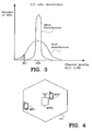
- FIG. 1 displays a principle sketch of speech quality as a function of the channel quality for an example AMR codec with 3 modes. In this example, mode 3 has the highest source bit rate and thus the highest speech quality under error-free conditions. Modes 2 and 1 have lower source bit rates and correspondingly lower quality under error-free conditions.
- codec mode 3 is sensitive to channel errors and breaks down in channel conditions for which mode 2 and, particularly, mode 1 still exhibit robust operation.
- Codec mode 1 is the most robust mode and can operate under channel conditions where the other modes have already broken down.
- TAB. 1 Mode Bit rate [kb/s] AMR475 4.75 AMR515 5.15 AMR59 5.9 AMR67 6.7 AMR74 7.4 AMR795 7.95 AMR102 10.2 AMR122 12.2
- AMR codec mode adaptation The principle operation of AMR codec mode adaptation is as follows. Incoming speech is source and channel encoded, see the Speech Encoder block SPE in FIG. 5 , applying the currently selected codec and channel modes. The resulting payload gross bits are transmitted over the air interface together with adaptation data from codec mode adaptation.
- Codec mode adaptation data consists either of link measurement data, i.e. any data reflecting the estimated channel quality/capacity or of a codec mode request MR1,MR2 informing the sending side, first mobile station MS1, about the codec mode it should select.
- the receiving side, second mobile station MS2 detects the codec mode used and applies it for channel and source decoding of the received speech payload data in Speech Decoder block SPD.
- the received link measurement data or codec mode request is used for choosing the codec mode for the outgoing second link UL2.
- the receiving side, second mobile station MS2 performs measurements on the incoming second link DL2, which leads to link measurement data or a codec mode request MR2 for that link.
- Link measurement data is generated by a link measurement device second Link Adaptation block LA2 in the receiving side, second mobile station MS2. It is indicative of the measured quality of the incoming link. This data can - after suitable quantization - be directly transmitted to the sending side, first mobile station MS1, or it can first be fed into an adapter device, second Link Adaptation block LA2.
- the adapter generates a codec mode request, second AMR mode code request MR2, or a command in response to the measurement data, which is an indication of the codec mode to be used by the sending side, first mobile station MS1. If this adapter, second Link Adaptation block LA2, is located on the receiving side, second mobile station MS2, the corresponding codec mode request/command, second AMR mode request MR2 is sent to the sending side, first mobile station MS1, instead of the original measurement data. However, if the adapter, first Link Adaptation block LA1, is located at the sending side, first mobile station MS1, the measurement data has to be transmitted to that side.
- coders such as e.g. audio, video or speech coders with the same/similar characteristics as the AMR speech coder may be used in the future.
- first base station BTS1 and second base station BTS2 are in communication with a base station controller BSC1.
- base station controller BSC1 As a person skilled in the art appreciates, first MS1 and second MS2 mobile station can be in communication with the same base station, the parts of uplink and downlink communication is then physically separated in the one base station, this is not shown in FIG 3 , or separated by using different timeslots or channel frequencies.
- first base station BTS1 and second base station BTS2 are two transcoder units, first transcoder unit TRAU1 and second transcoder unit TRAU2. In a tandem free connection en- and decoding is not needed whereby the transcoding units are bypassed.
- a binding codec mode request is usually referred to as "codec mode command” whereas if this is merely the indication of the preferred mode and the sending side has the authority to override it, it is referred to as “codec mode request” MR.
- codec mode request MR
- AMR coded mode requests MRs are generated by the codec mode adaptation device based on an estimate of the channel quality. This operation is a mapping of the measurement to the AMR coded mode request MR. This may involve the comparison of the measurement values with certain thresholds. The measurements can be any channel quality estimate. Usually, as it is specified in GSM 05.09, MRs are generated by comparing a filtered carrier-to-interference (C/I) ratio measurement value with some thresholds.
- C/I carrier-to-interference
- Filtering of measurement values is usually done with a filter having memory since instantaneous measurements taken from only one time-division multiple-access (TDMA) burst or one frame usually are too strongly fluctuating.
- the purpose of the filtering is to generate a measurement value which deviates less from the expectation of the true value than the instantaneous measurements.
- Typical filters are linear smoothing and prediction filters having a length of 500 ms. Examples for such filters are given in 'GSM 05.09: Link Adaptation'.
- the AMR speech coding standard comprises of 8 different modes but for efficiency reasons only 4 out of the 8 modes are allowed at call setup. Thus, if the MRs are transmitted using a block code, the code could comprise 4 different code words which would allow to directly signal any of the modes.
- the first base station BTS1 measures the quality of the first uplink UL1. Based on this measurement the first base station BTS1 sends a command to the first mobile station MS1 to select the appropriate coder mode.
- the system is symmetrical i.e. the second mobile station MS2 normally controls the second downlink DL2 mode MR2 but there is a possibility for the second base station BTS2 to override the second mode requested MR2 by the second mobile station MS2. This feature can be used in tandem free connection and can also be used to compensate for poor mobile station implementations.
- tandem free in the context of this invention does include both the case where the network transcoder is in the speech path (normally referred to as tandem free operation) and the case with no network transcoder (normally referred to as transcoder free operation).
- the second mobile station MS2 is closer to the base station BTS1, and accordingly having a better link than the first mobile station MS1 being further away from the base station BTS1.
- first uplink UL1 in series with second downlink DL2
- second uplink UL2 in series with first downlink DL1 in FIG. 5 .
- the example of first mobile station MS1 and second mobile station MS2 in FIG. 4 is illustrated by the block diagram in FIG. 5 .
- the quality of the first uplink UL1 from a first mobile station MS1 to a first base station BTS1 is monitored by the first link adaptation LA1 in first base station BTS1 and the quality of the downlink from second base station BTS2 to second mobile station MS2 is monitored by the second link adaptation LA2 in second mobile station MS2.
- second downlink DL2 is having very good radio conditions (high carrier-to-interference C/I ratio) and therefore the link adaptation requests e.g. will be the high rate mode, AMR102, see TAB. 1, from the other end. If this had been a mobile to landline call this request would have been granted by second base station BTS2. In a mobile to mobile call the request has to be passed on to first base station BTS1.
- the radio link conditions on first uplink UL1 is poor and the first link adaptation LA1 in first base station BTS1 requests e.g. the robust mode AMR515.
- the optimal mode to use is the AMR515.
- first base station BTS1 after first link adaptation LA1 that combines (see block CCM, Combined Code Mode) the mode requests MR1,MR2 for the two links, first uplink UL1 and second downlink DL2, and selects the lower of the two which is passed on to first mobile station MS1. From a speech quality point of view this is the optimal choice.
- This may not be obvious but the alternative to introduce two stages of speech coding is always degrading the speech quality more. For example, AMR515 in a single encoding is always better than AMR515 in tandem with AMR102.
- the power control In the GSM system there is a function called power control.
- the purpose of the power control is to increase the transmitting power for the users that have a poor carrier-to-interference C/I ratio and decrease it for the users that have a too good C/I.
- the speech quality is too low and need to be improved and in exemplary latter case for second mobile station MS2 it is a waste of resources to have a C/I ratio above the level which gives acceptable speech quality.
- an optimal C/I ratio 210 can be obtained, this optimal C/I ratio 210 is normally just before the AMR coded mode curve is straightening, see point 212 for AMR515 in FIG. 2 .
- the C/I ratio point 230 illustrate the point 232 where an optimal C/I ratio is obtained for the higher AMR coded mode AMR102.
- the curve starts straightening, and between that C/I point 220,222 and a C/I point 230,223, the speech quality 221 is at the same level.
- a first example is the situation of suddenly degrading radio channels. Assume first that the C/I ratio on first uplink UL1 gets worse than required for the codec mode presently used by first mobile station MS1. In this case first base station BTS1 would sense the degraded channel condition and send the request for a more robust mode to first mobile station MS1. The adaptation action would comprise the short effective control loop: BTS1 - DL1 - MS1 - UL1.
- a second example is the case that the C/I on second downlink DL2 gets worse than required for the codec mode presently used.
- second mobile station MS2 would sense the degraded channel condition and request a more robust mode.
- This request is sent via second uplink UL2 to second base station BTS2 from where it is propagated through air to first base station BTS1.
- First base station BTS1 sends this request further to first mobile station MS1 provided that it is lower than required for first uplink UL1.
- the adaptation action would comprise the big effective control loop: MS2 - UL2 - BTS2 - BTS1 - DL1 - MS1 - UL1 - BTS1 - BTS2 - DL2.
- the first base station controller BSC1 can be an over all control unit.
- the problem with the situation described in the first and second example in section above is not so much loss in speech quality.
- the worst of the two radio links acts as a bottleneck and sets the limit for the achievable speech quality; this can not be solved.
- the problem in this case is that the good radio link uses excessive power. This can be translated to a capacity loss in the system.
- the power control algorithm can adjust (e.g. from C/I ratio at 230 to C/I ratio at 210) the power to avoid excessive C/I ratio 230 on the good link.
- the capacity gain will depend on the number of mobile to mobile calls in the system and also on the C/I distribution.
- the good link if the good link requesting the AMR coded mode AMR102 with the optimal C/I ratio 230, and bad link requesting the AMR coded mode AMR515 with optimal C/I ratio 210, the good link can lower its optimal C/I ratio 230 to C/I ratio 220 without loosing in speech quality for the combined lower AMR coded mode AMR515.
- the target C/I ratio for the power control is set to a level that gives the desired speech quality, see FIG. 2 .
- one of the AMR modes is the optimal, normally one of the highest rate modes.
- one of the mobiles e.g. second mobile station MS2 with a good link, second downlink DL2, may be forced by the poor link, first uplink UL1, to use a more robust AMR mode AMR515.
- second downlink DL2 in this case will be of no use since it is above the C/I 230 ratio for which the quality of the more robust mode AMR515 is improved, it can be lowered from point 223 to point 222 without decreasing the speech quality 221 as can be seen in FIG. 2 .
- a sensor in e.g. the downlink power control DL PC in second base station BTS2 compares the second codec mode request MR2 from second mobile station MS2 with the presently applied codec mode MR1" (MR1bis) on second downlink DL2.
- the second downlink power 511 is adjusted accordingly by a power command 530.
- the second codec mode request MR2 is passed on to first base station BTS1.
- the second codec mode requested MR2, passed on to first base station BTS1 is compared with first codec mode requested MR1 and the first uplink power 510 is adjusted accordingly by a power command 520.
- the downlink power 511 is decreased for that connection to a power level lower than the optimal power level for the connection with the highest associated C/I ratio.
- the second downlink DL2 connection is associated with the highest C/I ratio.
- the uplink power 510 is decreased for that connection to a power level lower than the optimal power level for the connection with the highest associated C/I ratio.
- the first uplink UL1 connection is associated with the highest C/I ratio.
- the incoming signals to uplink power control UL PC can e.g. be first MR1 and second MR2 requested modes, but can also be MR1 and the applied combined codec mode in block CCM in FIG. 5 .
- the transmit power 510 is decreased for that connection. This action leads to a lower C/I (C/I at 230 compared to C/I at 220 in FIG. 2 ) on the first uplink UL1 but this will not decrease the speech quality 221.
- the decreased power will on the other hand reduce interference in the system. It is expected that the proposed decrease of the transmission power will lead to significant system capacity savings.
- the flowchart 600 of FIG. 6 illustrates a first exemplary embodiment of the invention according to which a power control is modified to incorporate either the uplink or the downlink lower power control level for the connection with the highest C/I ratio.
- a radio communication system SYS1 comprising of first base station BTS1 and second base station BTS2 and first mobile station MS1 and second mobile station MS2.
- the first mobile station MS1 communicates in an uplink UL1 connection with an uplink power 510 with the first base station BTS1.
- the second base station BTS2 communicates in a downlink DL2 connection with a downlink power 511 with the second mobile station MS2.
- the first base station BTS1 requests a first AMR coded mode MR1 which is associated with a first C/I ratio 210,230.
- the second mobile station MS2 requests a second AMR coded mode MR2 which is associated with a second C/I ratio 210,230.
- Either the uplink power 510 or the downlink power 511 is adjusted to a power level lower than an optimal power level for the connection UL1,DL2 with the highest associated C/I 230 ratio.
- the power 510, 511 is adjusted to a power level corresponding to an optimal power level for the connection with the lowest associated C/I ratio 210.
- the power level can go below what is an optimal level 212 for the corresponding AMR coded mode e.g. AMR515 if that gives a speech quality which is appropriate for both mobile stations MS1,MS2.
- the uplink power 510 from the first mobile station MS1 is controlled by a command 520 from the first base station BTS1 in step 607, and the downlink power 511 in step 608 from the second mobile station MS2 is controlled by a command 530 from the second base station BTS2.
- one base station unit may be used or the power level can be adjusted from a base station controller BSC1.
- the flowchart 700 of FIG. 7 illustrates a second exemplary embodiment of the invention according to which a power control is modified to incorporate either the uplink or downlink lower power control level for the connection with the highest AMR coded mode request AMR102.
- a radio communication system SYS1 comprising of first base station BTS1 and second base station BTS2 and first mobile station MS1 and second mobile station MS2.
- the first mobile station MS1 communicates in an uplink UL1 connection with an uplink power 510 with the first base station BTS1.
- the second base station BTS2 communicates in a downlink DL2 connection with a downlink power 511 with the second mobile station MS2.
- the first base station BTS1 requests a first AMR coded mode MR1.
- the second mobile station MS2 requests a second AMR coded mode MR2.
- Either the uplink power 510 or the downlink power 511 is adjusted to a power level lower than an optimal power level for the connection UL1,DL2 with the highest AMR coded mode request MR1,MR2,AMR102.
- the power 510,511 is adjusted to a power level corresponding to an optimal power level for the connection with the lowest AMR coded mode request MR1,MR2,AMR515.
- the power level can go below what is an optimal level 212 for the corresponding AMR coded mode e.g. AMR515 if that gives a speech quality which is appropriate for both mobile stations MS1,MS2.
- the uplink power 510 from the first mobile station MS1 is controlled by a command 520 from the first base station BTS1 in step 707, and the downlink power 511 in step 708 from the second mobile station MS2 is controlled by a command 530 from the second base station BTS2.
- a command 520 from the first base station BTS1 in step 707 and the downlink power 511 in step 708 from the second mobile station MS2 is controlled by a command 530 from the second base station BTS2.
- one base station unit may be used or the power level can be adjusted from a base station controller BSC1.
- the second base station BTS2 comprises e.g. in block Downlink Power Control DL PC means for adjusting the downlink power 511 to a power level lower than an optimal power level 232 for the connection with the highest associated C/I 230 ratio.
- the first base station BTS1 comprises in block Uplink Power Control UL PC means for sending an uplink power command 520 for adjusting the uplink power 510 to a power level lower than an optimal power level for the connection with the highest associated C/I 230 ratio.
- the second base station BTS2 comprises e.g. in block Downlink Power Control DL PC means for adjusting the downlink power 511 to a power level lower than an optimal power level 232 for the connection with the highest AMR coded mode request AMR102.
- the first base station BTS1 comprises e.g. in block Uplink Power Control UL PC means for sending an uplink power command 520 for adjusting the uplink power 510 to a power level lower than an optimal power level 232 for the connection with the highest AMR coded mode request.
- Uplink Power Control UL PC means for sending an uplink power command 520 for adjusting the uplink power 510 to a power level lower than an optimal power level 232 for the connection with the highest AMR coded mode request.
- DTX is a technique essentially turning off transmission during periods of speech inactivity.
- the purpose of DTX is to reduce the interference level in a radio network and thus to increase capacity.
- DTX helps to decrease battery drain in Mobile Stations and thus to extend talktime.
- DTX does not totally turn off transmission during speech inactivity.
- so-called Silence Descriptor frames (SID) conveying a description of the background noise characteristics are transmitted to the receiver enabling it to generate a comfort noise signal.
- SID frames are transmitted at a rate of once per 8 frames (160 ms) (see GSM 06.93).
- AMR SID frames do not only convey comfort noise parameters.
- they comprise coded mode adaptation data, which, apart from other data, are the MRs for the other link. These CMRs are encoded using a 16 bit block code (see GSM 05.03).
- application of the invention is in no way limited to only cellular radio communication networks conforming to the GSM specification.
- the AMR speech coder is also specified for Universal Mobile Telecommunications Service (UMTS) even though a link adaptation system similar to GSM is not specified.
- UMTS Universal Mobile Telecommunications Service
- the same basic principle is however applicable to UMTS regardless of how the AMR mode is selected on the two radio links in a UMTS mobile to mobile call.
- CDMA Code Division Multiple Access
Landscapes
- Engineering & Computer Science (AREA)
- Signal Processing (AREA)
- Computer Networks & Wireless Communication (AREA)
- Computational Linguistics (AREA)
- Health & Medical Sciences (AREA)
- Audiology, Speech & Language Pathology (AREA)
- Human Computer Interaction (AREA)
- Physics & Mathematics (AREA)
- Acoustics & Sound (AREA)
- Multimedia (AREA)
- Mobile Radio Communication Systems (AREA)
- Transmitters (AREA)
Claims (15)
- Verfahren zum Steuern von Sendeleistung in einem Funkkommunikationssystem (SYS1), eine erste Mobilstation (MS1) und eine zweite Mobilstation (MS2) umfassend;
eine erste Basisstation (BTS1) und eine zweite Basisstation (BTS2);
wobei die erste Mobilstation (MSS1) über eine Uplink(UL1)-Verbindung mit einer Uplinkleistung (510) mit der ersten Basisstation (BTS1) kommuniziert (601);
die zweite Basisstation (BTS2) über eine Downlink(DL2)-Verbindung mit einer Downlinkleistung (511) mit der zweiten Mobilstation (MS2) kommuniziert (602);
die erste Basisstation (BTS1) einen ersten adaptiven Mehrraten-Kodiermodus (MR1) anfordert (603), der mit einem ersten Träger-Störungs(C/I)-Verhältnis (210, 230) assoziiert ist;
die zweite Mobilstation (MS2) einen zweiten adaptiven Mehrraten-Kodiermodus (MR2) anfordert (604), der mit einem zweiten C/I-Verhältnis (210, 230) assoziiert ist;
dadurch gekennzeichnet, dass das Verfahren folgende Schritte umfasst:Anpassen (605) entweder der Uplinkleistung (510) oder der Downlinkleistung (511) an einen Leistungspegel, der unter einem optimalen Leistungspegel (232) liegt, der mit einem optimalen C/I-Verhältnis (230) assoziiert ist, das für den adaptiven Mehrraten-Kodiermodus erlangt werden kann, der für die Verbindung (UL1, DL2) mit dem höchsten assoziierten C/I-Verhältnis (230) benutzt wird. - Verfahren zum Steuern von Sendeleistung in einem Funkkommunikationssystem (SYS1), eine erste Mobilstation (MS 1) und eine zweite Mobilstation (MS2) umfassend;
eine erste Basisstation (BTS1) und eine zweite Basisstation (BTS2);
wobei die erste Mobilstation (MS1) über eine Uplink(UL1)-Verbindung mit einer Uplinkleistung (510) mit der ersten Basisstation (BTS1) kommuniziert (701);
die zweite Basisstation (BTS2) über eine Downlink(DL2)-Verbindung mit einer Downlinkleistung (511) mit der zweiten Mobilstation (MS2) kommuniziert (702);
die erste Basisstation (BTS1) einen ersten adaptiven Mehrraten-Kodiermodus (MR1) anfordert (703);
die zweite Mobilstation (MS2) einen zweiten adaptiven Mehrraten-Kodiermodus (MR2) anfordert (704);
dadurch gekennzeichnet, dass das Verfahren folgende Schritte umfasst:Anpassen (705) entweder der Uplinkleistung (510) oder der Downlinkleistung (511) an einen Leistungspegel, der unter einem optimalen Leistungspegel (232) liegt, der mit einem optimalen C/I-Verhältnis (230) assoziiert ist, das für den adaptiven Mehrraten-Kodiermodus erlangt werden kann, der für die Verbindung mit der höchsten adaptiven Mehrraten-Kodiermodus-Anforderung (AMR102) benutzt wird,worin der höchste adaptive Mehrratenmodus der Modus mit der höchsten Quellbitrate ist. - Verfahren nach Anspruch 1,
worin entweder die Uplinkleistung (510) oder die Downlinkleistung (511) an einen Leistungspegel angepasst (606) wird, der einem optimalen Leistungspegel (212) für die Verbindung mit dem niedrigsten assoziierten C/I-Verhältnis (210) entspricht. - Verfahren nach Anspruch 2,
worin entweder die Uplinkleistung (510) oder die Downlinkleistung (511) an einen Leistungspegel angepasst (706) wird, der einem optimalen Leistungspegel (212) entspricht, der mit einem optimalen C/I-Verhältnis (230) assoziiert ist, das für den adaptiven Mehrraten-Kodiermodus erlangt werden kann, der für die Verbindung mit der niedrigsten adaptiven Mehrraten-Kodiermodus-Anforderung (AMR515) benutzt wird, worin der niedrigste adaptive Mehrratenmodus der Modus mit der niedrigsten Quellbitrate ist. - Verfahren nach einem der Ansprüche 1-4,
worin das Anpassen (607, 707) der Uplinkleistung (510) durch Steuern der Uplinkleistung (520) von der ersten Mobilstation (MS1) durch einen Befehl (520) von der ersten Basisstation (BTS1) an die erste Mobilstation (MS1) ausgeführt wird. - Verfahren nach einem der Ansprüche 1-4,
worin das Anpassen (608, 708) der Downlinkleistung (511) durch Steuern der Downlinkleistung (530) von der zweiten Basisstation (BTS2) ausgeführt wird. - Verfahren nach einem der Ansprüche 1-6,
worin die erste Basisstation (BTS1) und die zweite Basisstation (BTS2) Bestandteile einer gemeinsamen Basisstationseinheit sind. - Verfahren nach einem der Ansprüche 1-4,
worin das Anpassen (607, 707) der Uplinkleistung (510) durch Steuern der Uplinkleistung (520) von der ersten Mobilstation (MS1) durch einen Befehl (520) von einem Basisstationscontroller (BSC1) an die erste Mobilstation (MS1) ausgeführt wird. - Verfahren nach einem der Ansprüche 1-4, worin das Anpassen (608, 708) der Downlinkleistung (511) durch Steuern der Downlinkleistung (530) von einem Basisstationscontroller (BSC1) ausgeführt wird.
- Funkkommunikationssystem (SYS1), umfassend:eine erste Mobilstation (MS1) und eine zweite Mobilstation (MS2);eine erste Basisstation (BTS1) und eine zweite Basisstation (BTS2);wobei die erste Mobilstation (MS1) über eine Uplink(UL1)-Verbindung mit einer Uplinkleistung (510) mit der ersten Basisstation (BTS1) kommuniziert;
die zweite Basisstation (BTS2) über eine Downlink(DL2)-Verbindung mit einer Downlinkleistung (511) mit der zweiten Mobilstation (MS2) kommuniziert;
die erste Basisstation (BTS1) einen ersten adaptiven Mehrraten-Kodiermodus (MR1) anfordert, der mit einem ersten C/I-Verhältnis (210, 230) assoziiert ist; die zweite Mobilstation (MS2) einen zweiten adaptiven Mehrraten-Kodiermodus (MR2) anfordert, der mit einem zweiten C/I-Verhältnis (210, 230) assoziiert ist;
dadurch gekennzeichnet, dass die zweite Basisstation (BTS2) umfasst:ein Mittel zum Anpassen (DL PC) der Downlinkleistung (511) auf einen Leistungspegel, der unter einem optimalen Leistungspegel (232) liegt, der mit einem optimalen C/I-Verhältnis (230) assoziiert ist, das für den adaptiven Mehrraten-Kodiermodus erlangt werden kann, der für die Verbindung mit dem höchsten assoziierten C/I-Verhältnis (230) benutzt wird; unddie erste Basisstation (BTS1) umfasst:ein Mittel zum Senden (UL PC) eines Uplinkleistungsbefehls (520) zum Anpassen (UL PC) der Uplinkleistung (510) an einen Leistungspegel, der mit einem optimalen C/I-Verhältnis (230) assoziiert ist, das für den adaptiven Mehrraten-Kodiermodus erlangt werden kann, der niedriger benutzt wird als ein optimaler Leistungspegel für die Verbindung mit dem höchsten assoziierten C/I-Verhältnis (230). - Funkkommunikationssystem (SYS1), eine erste Mobilstation (MS1) und eine zweite Mobilstation (MS2) umfassend; eine erste Basisstation (BTS1) und eine zweite Basisstation (BTS2); wobei die erste Mobilstation (MS1) über eine Uplink(UL1)-Verbindung mit einer Uplinkleistung (510) mit der ersten Basisstation (BTS1) kommuniziert; die zweite Basisstation (BTS2) über eine Downlink(DL2)-Verbindung mit einer Downlinkleistung (511) mit der zweiten Mobilstation (MS2) kommuniziert; die erste Basisstation (BTS1) einen ersten adaptiven Mehrraten-Kodiermodus (MR1) anfordert;
die zweite Mobilstation (MS2) einen zweiten adaptiven Mehrraten-Kodiermodus (MR2) anfordert; dadurch gekennzeichnet, dass die erste Basisstation (BTS1) umfasst: ein Mittel zum Senden (UL PC) eines Uplinkleistungsbefehls (520) zum Anpassen der Uplinkleistung (510) an einen Leistungspegel, der unter einem optimalen Leistungspegel (232) liegt, der mit einem optimalen C/I-Verhältnis (230) assoziiert ist, das für den adaptiven Mehrraten-Kodiermodus erlangt werden kann, der für die Verbindung mit der höchsten adaptiven Mehrraten-Kodiermodus-Anforderung (AMR102) benutzt wird; und dadurch, dass die zweite Basisstation (BTS2) umfasst:ein Mittel zum Senden (DL PC) des Downlinkleistungsbefehls (530) an einen Leistungspegel, der unter einem optimalen Leistungspegel (232) liegt, der mit einem optimalen C/I-Verhältnis (230) assoziiert ist, das für den adaptiven Mehrraten-Kodiermodus erhalten werden kann, der für die Verbindung mit der höchsten adaptiven Mehrraten-Kodiermodus-Anforderung (AMR102) benutzt wird, worin der höchste adaptive Mehrratenmodus der Modus mit der höchsten Quellbitrate ist. - Funkkommunikationssystem nach Anspruch 10 und 11,
worin die erste Mobilstation (MS1) einen Empfänger zum Empfangen eines Uplinkleistungsbefehls (520) von der ersten Basisstation (BTS1) umfasst. - Funkkommunikationssystem nach den Ansprüchen 10 und 11,
worin das Mittel zum Anpassen (UL PC, DL PC) in der ersten (BTS1) oder zweiten Basisstation (BTS2) oder in einem Basisstationscontroller (BSC1) im Funkkommunikationssystem (SYS1) angeordnet ist. - Funkkommunikationssystem nach den Ansprüchen 10 und 11,
worin das Mittel zum Senden (UL PC, DL PC) eines Downlink- (530) oder Uplinkleistungsbefehls (520) zum Anpassen (UL PC, DL PC) der Downlink- (511) oder Uplinkleistung (510) in der ersten Basisstation (BTS1) oder der zweiten Basisstation (BTS2) oder in einem Basisstationscontroller (BSC1) im Funkkommunikationssystem (SYS1) angeordnet ist. - Funkkommunikationssystem nach einem der Ansprüche 10-11,
worin die erste Basisstation (BTS1) und die zweite Basisstation (BTS2) Bestandteile einer gemeinsamen Basisstationseinheit sind.
Applications Claiming Priority (3)
| Application Number | Priority Date | Filing Date | Title |
|---|---|---|---|
| WOPCT/SE02/00692 | 2002-04-03 | ||
| PCT/SE2002/000692 WO2003084090A1 (en) | 2002-04-03 | 2002-04-03 | Power control in mobile communication system |
| PCT/SE2003/000534 WO2003084091A1 (en) | 2002-04-03 | 2003-04-02 | Power control in mobile communication systems |
Publications (2)
| Publication Number | Publication Date |
|---|---|
| EP1493237A1 EP1493237A1 (de) | 2005-01-05 |
| EP1493237B1 true EP1493237B1 (de) | 2009-06-17 |
Family
ID=28673181
Family Applications (1)
| Application Number | Title | Priority Date | Filing Date |
|---|---|---|---|
| EP03710592A Expired - Lifetime EP1493237B1 (de) | 2002-04-03 | 2003-04-02 | Leistungsregelung in mobilkommunikationssystemen |
Country Status (6)
| Country | Link |
|---|---|
| US (1) | US7328038B2 (de) |
| EP (1) | EP1493237B1 (de) |
| AT (1) | ATE434295T1 (de) |
| AU (2) | AU2002249746A1 (de) |
| DE (1) | DE60328006D1 (de) |
| WO (2) | WO2003084090A1 (de) |
Families Citing this family (14)
| Publication number | Priority date | Publication date | Assignee | Title |
|---|---|---|---|---|
| DE10337445B3 (de) * | 2003-08-14 | 2005-06-30 | Siemens Ag | Verfahren zum Betrieb eines Funkkommunikationssystems, Empfangsstation sowie Sendestation für ein Funkkommunkationssystem |
| WO2005034381A1 (en) * | 2003-10-09 | 2005-04-14 | Telefonaktiebolaget Lm Ericsson (Publ) | Power control relating to a radio communication system |
| US20050277425A1 (en) * | 2004-06-15 | 2005-12-15 | Kari Niemela | Method of controlling data transmission, radio system, controller, and base station |
| KR101055730B1 (ko) * | 2004-08-11 | 2011-08-11 | 엘지전자 주식회사 | 상향링크 전송 전력 스케줄링 방법 |
| US7639727B1 (en) * | 2004-10-05 | 2009-12-29 | Cingular Wireless Ii, L.L.C. | System and method for selecting wireless signal bandwidth based on signal strength measurements provided by wireless receivers |
| US7890072B2 (en) * | 2006-09-27 | 2011-02-15 | Silicon Laboratories, Inc. | Wireless communication apparatus for estimating(C/I) ratio using a variable bandwidth filter |
| KR101471563B1 (ko) * | 2008-07-10 | 2014-12-11 | 삼성전자주식회사 | 인지무선 통신시스템에서 프레임간 자원공유를 위한 방법및 장치 |
| US8275406B2 (en) * | 2009-04-30 | 2012-09-25 | Telefonaktiebolaget L M Ericsson (Publ) | Integrated power control and link adaptation |
| US8260610B2 (en) * | 2009-10-07 | 2012-09-04 | Nokia Corporation | VAMOS—DARP receiver switching for mobile receivers |
| US8554259B2 (en) * | 2009-12-14 | 2013-10-08 | Apple Inc. | Method and apparatus to improve the robustness of a wireless communication link |
| US8898060B2 (en) * | 2010-03-02 | 2014-11-25 | Telefonaktiebolaget L M Ericsson (Publ) | Source code adaption based on communication link quality and source coding delay |
| US9042930B1 (en) * | 2010-09-13 | 2015-05-26 | Sprint Spectrum L.P. | Method and system for reducing forward link transmission power |
| WO2013061113A1 (en) * | 2011-10-25 | 2013-05-02 | Nokia Corporation | A method and apparatus for audio coding using context dependent information |
| US10091735B2 (en) * | 2012-12-13 | 2018-10-02 | Futurewei Technologies, Inc. | Systems and methods for power control in wireless networks |
Family Cites Families (14)
| Publication number | Priority date | Publication date | Assignee | Title |
|---|---|---|---|---|
| US5345598A (en) | 1992-04-10 | 1994-09-06 | Ericsson-Ge Mobile Communications Holding, Inc. | Duplex power control system in a communication network |
| FR2718906B1 (fr) * | 1994-04-13 | 1996-05-24 | Alcatel Mobile Comm France | Procédé d'adaptation de l'interface air, dans un système de radiocommunication avec des mobiles, station de base, station mobile et mode de transmission correspondants. |
| SE9601606D0 (sv) * | 1996-04-26 | 1996-04-26 | Ericsson Telefon Ab L M | Sätt vid radiotelekommunikationssystem |
| US5909469A (en) * | 1997-08-29 | 1999-06-01 | Telefonaktoebolaget Lm Ericsson | Link adaptation method for links using modulation schemes that have different symbol rates |
| US6529730B1 (en) * | 1998-05-15 | 2003-03-04 | Conexant Systems, Inc | System and method for adaptive multi-rate (AMR) vocoder rate adaption |
| FI108202B (fi) * | 1998-12-22 | 2001-11-30 | Nokia Networks Oy | Signalointimenetelmä ja tietoliikennejärjestelmä |
| ES2213587T3 (es) * | 1999-07-05 | 2004-09-01 | Nokia Corporation | Procedimiento para seleccion del metodo de codificacion. |
| DE19931236C2 (de) * | 1999-07-07 | 2002-05-29 | Siemens Ag | Verfahren zur Zuweisung von Übertragungskapazität zu Verbindungen in einem Funk-Kommunikationssystem |
| US6385462B1 (en) | 2000-05-26 | 2002-05-07 | Motorola, Inc. | Method and system for criterion based adaptive power allocation in a communication system with selective determination of modulation and coding |
| SE517030C2 (sv) * | 2000-06-06 | 2002-04-02 | Ericsson Telefon Ab L M | Metod och anordning för val av modulerings- och kodningsregler i ett radiokommunikationssystem |
| US6697642B1 (en) * | 2000-07-19 | 2004-02-24 | Texas Instruments Incorporated | Wireless communications apparatus |
| US20020114284A1 (en) * | 2001-02-02 | 2002-08-22 | Fredric Kronestedt | Method and system for receiver-characterized power setting in a cellular communication system |
| JP3543959B2 (ja) * | 2001-02-16 | 2004-07-21 | 日本電気株式会社 | 基地局 |
| CN1167296C (zh) * | 2001-09-28 | 2004-09-15 | 华为技术有限公司 | 在通信系统中控制传输速率的方法和装置 |
-
2002
- 2002-04-03 AU AU2002249746A patent/AU2002249746A1/en not_active Abandoned
- 2002-04-03 WO PCT/SE2002/000692 patent/WO2003084090A1/en not_active Ceased
-
2003
- 2003-04-02 AT AT03710592T patent/ATE434295T1/de not_active IP Right Cessation
- 2003-04-02 DE DE60328006T patent/DE60328006D1/de not_active Expired - Lifetime
- 2003-04-02 WO PCT/SE2003/000534 patent/WO2003084091A1/en not_active Ceased
- 2003-04-02 AU AU2003214762A patent/AU2003214762A1/en not_active Abandoned
- 2003-04-02 US US10/509,825 patent/US7328038B2/en not_active Expired - Fee Related
- 2003-04-02 EP EP03710592A patent/EP1493237B1/de not_active Expired - Lifetime
Also Published As
| Publication number | Publication date |
|---|---|
| US20050136959A1 (en) | 2005-06-23 |
| AU2003214762A1 (en) | 2003-10-13 |
| WO2003084091A1 (en) | 2003-10-09 |
| ATE434295T1 (de) | 2009-07-15 |
| WO2003084090A1 (en) | 2003-10-09 |
| EP1493237A1 (de) | 2005-01-05 |
| AU2002249746A1 (en) | 2003-10-13 |
| US7328038B2 (en) | 2008-02-05 |
| DE60328006D1 (de) | 2009-07-30 |
Similar Documents
| Publication | Publication Date | Title |
|---|---|---|
| US6535723B1 (en) | Method of power control for a wireless communication system having multiple information rates | |
| US6173162B1 (en) | Multiple code channel power control in a radio communication system | |
| AU761352B2 (en) | Adaptive cell-level modulation and channel coding | |
| US6085108A (en) | Modified downlink power control during macrodiversity | |
| EP1493237B1 (de) | Leistungsregelung in mobilkommunikationssystemen | |
| US6717931B2 (en) | Adaptive spreading factor based on power control | |
| JP2002519937A (ja) | 通信システム容量を制御する方法および装置 | |
| CA2272353A1 (en) | Method and apparatus for adjusting thresholds and measurements of received signals by anticipating power control commands yet to be executed | |
| KR100800514B1 (ko) | 이동 통신 시스템, 무선 기지국 제어 장치 및 그 송수신전력 제어 방법 | |
| WO2000014908A1 (en) | Method for controlling power of communication system | |
| CN1098016C (zh) | 数字移动通信系统中设置业务等级 | |
| US20060209803A1 (en) | Output power weighting | |
| US20060293075A1 (en) | Method to improve outer loop power control | |
| KR100317263B1 (ko) | 다중 채널 구조를 갖는 단말에 대한 외부 루프 전력 제어 방법 | |
| EP1269677B1 (de) | Schätzung der kommunikationsqualität | |
| WO2005034381A1 (en) | Power control relating to a radio communication system | |
| KR20050055166A (ko) | 이동통신 시스템에서 데이터 전송률 제어 장치 및 방법 | |
| JP2004531961A (ja) | 移動体無線システムの各サービスに特有のビットレート適応パラメータを設定する方法 | |
| JP2002535872A5 (de) |
Legal Events
| Date | Code | Title | Description |
|---|---|---|---|
| PUAI | Public reference made under article 153(3) epc to a published international application that has entered the european phase |
Free format text: ORIGINAL CODE: 0009012 |
|
| 17P | Request for examination filed |
Effective date: 20041103 |
|
| AK | Designated contracting states |
Kind code of ref document: A1 Designated state(s): AT BE BG CH CY CZ DE DK EE ES FI FR GB GR HU IE IT LI LU MC NL PT RO SE SI SK TR |
|
| AX | Request for extension of the european patent |
Extension state: AL LT LV MK |
|
| 17Q | First examination report despatched |
Effective date: 20061201 |
|
| GRAP | Despatch of communication of intention to grant a patent |
Free format text: ORIGINAL CODE: EPIDOSNIGR1 |
|
| GRAS | Grant fee paid |
Free format text: ORIGINAL CODE: EPIDOSNIGR3 |
|
| GRAA | (expected) grant |
Free format text: ORIGINAL CODE: 0009210 |
|
| AK | Designated contracting states |
Kind code of ref document: B1 Designated state(s): AT BE BG CH CY CZ DE DK EE ES FI FR GB GR HU IE IT LI LU MC NL PT RO SE SI SK TR |
|
| REG | Reference to a national code |
Ref country code: GB Ref legal event code: FG4D |
|
| REG | Reference to a national code |
Ref country code: CH Ref legal event code: EP |
|
| REG | Reference to a national code |
Ref country code: IE Ref legal event code: FG4D |
|
| REF | Corresponds to: |
Ref document number: 60328006 Country of ref document: DE Date of ref document: 20090730 Kind code of ref document: P |
|
| PG25 | Lapsed in a contracting state [announced via postgrant information from national office to epo] |
Ref country code: AT Free format text: LAPSE BECAUSE OF FAILURE TO SUBMIT A TRANSLATION OF THE DESCRIPTION OR TO PAY THE FEE WITHIN THE PRESCRIBED TIME-LIMIT Effective date: 20090617 Ref country code: FI Free format text: LAPSE BECAUSE OF FAILURE TO SUBMIT A TRANSLATION OF THE DESCRIPTION OR TO PAY THE FEE WITHIN THE PRESCRIBED TIME-LIMIT Effective date: 20090617 |
|
| PG25 | Lapsed in a contracting state [announced via postgrant information from national office to epo] |
Ref country code: SI Free format text: LAPSE BECAUSE OF FAILURE TO SUBMIT A TRANSLATION OF THE DESCRIPTION OR TO PAY THE FEE WITHIN THE PRESCRIBED TIME-LIMIT Effective date: 20090617 Ref country code: SE Free format text: LAPSE BECAUSE OF FAILURE TO SUBMIT A TRANSLATION OF THE DESCRIPTION OR TO PAY THE FEE WITHIN THE PRESCRIBED TIME-LIMIT Effective date: 20090917 |
|
| NLV1 | Nl: lapsed or annulled due to failure to fulfill the requirements of art. 29p and 29m of the patents act | ||
| PG25 | Lapsed in a contracting state [announced via postgrant information from national office to epo] |
Ref country code: RO Free format text: LAPSE BECAUSE OF FAILURE TO SUBMIT A TRANSLATION OF THE DESCRIPTION OR TO PAY THE FEE WITHIN THE PRESCRIBED TIME-LIMIT Effective date: 20090617 Ref country code: CZ Free format text: LAPSE BECAUSE OF FAILURE TO SUBMIT A TRANSLATION OF THE DESCRIPTION OR TO PAY THE FEE WITHIN THE PRESCRIBED TIME-LIMIT Effective date: 20090617 Ref country code: EE Free format text: LAPSE BECAUSE OF FAILURE TO SUBMIT A TRANSLATION OF THE DESCRIPTION OR TO PAY THE FEE WITHIN THE PRESCRIBED TIME-LIMIT Effective date: 20090617 Ref country code: ES Free format text: LAPSE BECAUSE OF FAILURE TO SUBMIT A TRANSLATION OF THE DESCRIPTION OR TO PAY THE FEE WITHIN THE PRESCRIBED TIME-LIMIT Effective date: 20090928 |
|
| PG25 | Lapsed in a contracting state [announced via postgrant information from national office to epo] |
Ref country code: BE Free format text: LAPSE BECAUSE OF FAILURE TO SUBMIT A TRANSLATION OF THE DESCRIPTION OR TO PAY THE FEE WITHIN THE PRESCRIBED TIME-LIMIT Effective date: 20090617 Ref country code: SK Free format text: LAPSE BECAUSE OF FAILURE TO SUBMIT A TRANSLATION OF THE DESCRIPTION OR TO PAY THE FEE WITHIN THE PRESCRIBED TIME-LIMIT Effective date: 20090617 Ref country code: NL Free format text: LAPSE BECAUSE OF FAILURE TO SUBMIT A TRANSLATION OF THE DESCRIPTION OR TO PAY THE FEE WITHIN THE PRESCRIBED TIME-LIMIT Effective date: 20090617 |
|
| PG25 | Lapsed in a contracting state [announced via postgrant information from national office to epo] |
Ref country code: PT Free format text: LAPSE BECAUSE OF FAILURE TO SUBMIT A TRANSLATION OF THE DESCRIPTION OR TO PAY THE FEE WITHIN THE PRESCRIBED TIME-LIMIT Effective date: 20091017 Ref country code: BG Free format text: LAPSE BECAUSE OF FAILURE TO SUBMIT A TRANSLATION OF THE DESCRIPTION OR TO PAY THE FEE WITHIN THE PRESCRIBED TIME-LIMIT Effective date: 20090917 |
|
| PLBE | No opposition filed within time limit |
Free format text: ORIGINAL CODE: 0009261 |
|
| STAA | Information on the status of an ep patent application or granted ep patent |
Free format text: STATUS: NO OPPOSITION FILED WITHIN TIME LIMIT |
|
| PG25 | Lapsed in a contracting state [announced via postgrant information from national office to epo] |
Ref country code: DK Free format text: LAPSE BECAUSE OF FAILURE TO SUBMIT A TRANSLATION OF THE DESCRIPTION OR TO PAY THE FEE WITHIN THE PRESCRIBED TIME-LIMIT Effective date: 20090617 |
|
| 26N | No opposition filed |
Effective date: 20100318 |
|
| PG25 | Lapsed in a contracting state [announced via postgrant information from national office to epo] |
Ref country code: GR Free format text: LAPSE BECAUSE OF FAILURE TO SUBMIT A TRANSLATION OF THE DESCRIPTION OR TO PAY THE FEE WITHIN THE PRESCRIBED TIME-LIMIT Effective date: 20090918 |
|
| PG25 | Lapsed in a contracting state [announced via postgrant information from national office to epo] |
Ref country code: MC Free format text: LAPSE BECAUSE OF NON-PAYMENT OF DUE FEES Effective date: 20100430 |
|
| REG | Reference to a national code |
Ref country code: CH Ref legal event code: PL |
|
| GBPC | Gb: european patent ceased through non-payment of renewal fee |
Effective date: 20100402 |
|
| REG | Reference to a national code |
Ref country code: FR Ref legal event code: ST Effective date: 20101230 |
|
| PG25 | Lapsed in a contracting state [announced via postgrant information from national office to epo] |
Ref country code: IE Free format text: LAPSE BECAUSE OF NON-PAYMENT OF DUE FEES Effective date: 20100402 |
|
| PG25 | Lapsed in a contracting state [announced via postgrant information from national office to epo] |
Ref country code: CH Free format text: LAPSE BECAUSE OF NON-PAYMENT OF DUE FEES Effective date: 20100430 Ref country code: LI Free format text: LAPSE BECAUSE OF NON-PAYMENT OF DUE FEES Effective date: 20100430 |
|
| PG25 | Lapsed in a contracting state [announced via postgrant information from national office to epo] |
Ref country code: GB Free format text: LAPSE BECAUSE OF NON-PAYMENT OF DUE FEES Effective date: 20100402 Ref country code: IT Free format text: LAPSE BECAUSE OF FAILURE TO SUBMIT A TRANSLATION OF THE DESCRIPTION OR TO PAY THE FEE WITHIN THE PRESCRIBED TIME-LIMIT Effective date: 20090617 |
|
| PG25 | Lapsed in a contracting state [announced via postgrant information from national office to epo] |
Ref country code: FR Free format text: LAPSE BECAUSE OF NON-PAYMENT OF DUE FEES Effective date: 20100430 |
|
| PG25 | Lapsed in a contracting state [announced via postgrant information from national office to epo] |
Ref country code: CY Free format text: LAPSE BECAUSE OF FAILURE TO SUBMIT A TRANSLATION OF THE DESCRIPTION OR TO PAY THE FEE WITHIN THE PRESCRIBED TIME-LIMIT Effective date: 20090617 |
|
| PG25 | Lapsed in a contracting state [announced via postgrant information from national office to epo] |
Ref country code: LU Free format text: LAPSE BECAUSE OF NON-PAYMENT OF DUE FEES Effective date: 20100402 Ref country code: HU Free format text: LAPSE BECAUSE OF FAILURE TO SUBMIT A TRANSLATION OF THE DESCRIPTION OR TO PAY THE FEE WITHIN THE PRESCRIBED TIME-LIMIT Effective date: 20091218 |
|
| PG25 | Lapsed in a contracting state [announced via postgrant information from national office to epo] |
Ref country code: TR Free format text: LAPSE BECAUSE OF FAILURE TO SUBMIT A TRANSLATION OF THE DESCRIPTION OR TO PAY THE FEE WITHIN THE PRESCRIBED TIME-LIMIT Effective date: 20090617 |
|
| REG | Reference to a national code |
Ref country code: DE Ref legal event code: R082 Ref document number: 60328006 Country of ref document: DE Representative=s name: HOFFMANN - EITLE, DE Effective date: 20140430 Ref country code: DE Ref legal event code: R081 Ref document number: 60328006 Country of ref document: DE Owner name: OPTIS WIRELESS TECHNOLOGY, LLC, PLANO, US Free format text: FORMER OWNER: TELEFONAKTIEBOLAGET LM ERICSSON (PUBL), STOCKHOLM, SE Effective date: 20140618 Ref country code: DE Ref legal event code: R082 Ref document number: 60328006 Country of ref document: DE Representative=s name: HOFFMANN - EITLE, DE Effective date: 20140618 Ref country code: DE Ref legal event code: R082 Ref document number: 60328006 Country of ref document: DE Representative=s name: GRUENECKER, KINKELDEY, STOCKMAIR & SCHWANHAEUS, DE Effective date: 20140430 Ref country code: DE Ref legal event code: R082 Ref document number: 60328006 Country of ref document: DE Representative=s name: GRUENECKER, KINKELDEY, STOCKMAIR & SCHWANHAEUS, DE Effective date: 20140618 Ref country code: DE Ref legal event code: R082 Ref document number: 60328006 Country of ref document: DE Representative=s name: GRUENECKER PATENT- UND RECHTSANWAELTE PARTG MB, DE Effective date: 20140618 Ref country code: DE Ref legal event code: R082 Ref document number: 60328006 Country of ref document: DE Representative=s name: GRUENECKER PATENT- UND RECHTSANWAELTE PARTG MB, DE Effective date: 20140430 |
|
| REG | Reference to a national code |
Ref country code: DE Ref legal event code: R082 Ref document number: 60328006 Country of ref document: DE Representative=s name: GRUENECKER, KINKELDEY, STOCKMAIR & SCHWANHAEUS, DE Ref country code: DE Ref legal event code: R082 Ref document number: 60328006 Country of ref document: DE Representative=s name: GRUENECKER PATENT- UND RECHTSANWAELTE PARTG MB, DE |
|
| PGFP | Annual fee paid to national office [announced via postgrant information from national office to epo] |
Ref country code: DE Payment date: 20170321 Year of fee payment: 15 |
|
| REG | Reference to a national code |
Ref country code: DE Ref legal event code: R119 Ref document number: 60328006 Country of ref document: DE |
|
| PG25 | Lapsed in a contracting state [announced via postgrant information from national office to epo] |
Ref country code: DE Free format text: LAPSE BECAUSE OF NON-PAYMENT OF DUE FEES Effective date: 20181101 |