EP1492397B1 - Heat exchanger - Google Patents
Heat exchanger Download PDFInfo
- Publication number
- EP1492397B1 EP1492397B1 EP04011900A EP04011900A EP1492397B1 EP 1492397 B1 EP1492397 B1 EP 1492397B1 EP 04011900 A EP04011900 A EP 04011900A EP 04011900 A EP04011900 A EP 04011900A EP 1492397 B1 EP1492397 B1 EP 1492397B1
- Authority
- EP
- European Patent Office
- Prior art keywords
- heat exchanging
- conduits
- inlet
- plenums
- outlet
- Prior art date
- Legal status (The legal status is an assumption and is not a legal conclusion. Google has not performed a legal analysis and makes no representation as to the accuracy of the status listed.)
- Expired - Lifetime
Links
- 239000012530 fluid Substances 0.000 claims description 28
- 238000004891 communication Methods 0.000 claims description 6
- WYTGDNHDOZPMIW-RCBQFDQVSA-N alstonine Natural products C1=CC2=C3C=CC=CC3=NC2=C2N1C[C@H]1[C@H](C)OC=C(C(=O)OC)[C@H]1C2 WYTGDNHDOZPMIW-RCBQFDQVSA-N 0.000 claims description 3
- 238000003491 array Methods 0.000 claims description 3
- 238000002955 isolation Methods 0.000 claims description 2
- 238000001816 cooling Methods 0.000 description 4
- 239000012809 cooling fluid Substances 0.000 description 4
- 238000010586 diagram Methods 0.000 description 3
- 238000005219 brazing Methods 0.000 description 2
- 239000000463 material Substances 0.000 description 2
- 238000000034 method Methods 0.000 description 2
- 229910052782 aluminium Inorganic materials 0.000 description 1
- XAGFODPZIPBFFR-UHFFFAOYSA-N aluminium Chemical compound [Al] XAGFODPZIPBFFR-UHFFFAOYSA-N 0.000 description 1
- 238000009792 diffusion process Methods 0.000 description 1
- 230000004941 influx Effects 0.000 description 1
- 229910052751 metal Inorganic materials 0.000 description 1
- 239000002184 metal Substances 0.000 description 1
- 238000012986 modification Methods 0.000 description 1
- 230000004048 modification Effects 0.000 description 1
- 238000010792 warming Methods 0.000 description 1
Images


Classifications
-
- H—ELECTRICITY
- H05—ELECTRIC TECHNIQUES NOT OTHERWISE PROVIDED FOR
- H05K—PRINTED CIRCUITS; CASINGS OR CONSTRUCTIONAL DETAILS OF ELECTRIC APPARATUS; MANUFACTURE OF ASSEMBLAGES OF ELECTRICAL COMPONENTS
- H05K7/00—Constructional details common to different types of electric apparatus
- H05K7/20—Modifications to facilitate cooling, ventilating, or heating
- H05K7/20218—Modifications to facilitate cooling, ventilating, or heating using a liquid coolant without phase change in electronic enclosures
- H05K7/20254—Cold plates transferring heat from heat source to coolant
-
- F—MECHANICAL ENGINEERING; LIGHTING; HEATING; WEAPONS; BLASTING
- F28—HEAT EXCHANGE IN GENERAL
- F28F—DETAILS OF HEAT-EXCHANGE AND HEAT-TRANSFER APPARATUS, OF GENERAL APPLICATION
- F28F3/00—Plate-like or laminated elements; Assemblies of plate-like or laminated elements
- F28F3/08—Elements constructed for building-up into stacks, e.g. capable of being taken apart for cleaning
- F28F3/086—Elements constructed for building-up into stacks, e.g. capable of being taken apart for cleaning having one or more openings therein forming tubular heat-exchange passages
-
- F—MECHANICAL ENGINEERING; LIGHTING; HEATING; WEAPONS; BLASTING
- F28—HEAT EXCHANGE IN GENERAL
- F28F—DETAILS OF HEAT-EXCHANGE AND HEAT-TRANSFER APPARATUS, OF GENERAL APPLICATION
- F28F3/00—Plate-like or laminated elements; Assemblies of plate-like or laminated elements
- F28F3/12—Elements constructed in the shape of a hollow panel, e.g. with channels
Definitions
- the subject disclosure is directed generally to heat exchangers, and more particularly to a heat exchanger that can be employed to cool electronics systems such as avionics systems.
- Typical heat exchangers used in the avionics industry use low density stamped or machined finstock (pins or pin fins) in the range of 12-30 fins per inch (fpi). These heat exchangers provide poor thermal heat transfer characteristics, yielding unit thermal conductances (UTC) on the order of 0.5 - 2.0 W/sq.-in°C.
- DE 202 08 106 U1 discloses a cooling device, wherein the part to be cooled is arranged at the upper side of a cooled plate, which lower side is cooled by a cooling fluid that is guided via a distributing element along the cooled plate.
- the fluid inlet and the fluid outlet of the distributing element are arranged orthogonally to the cooled plate.
- the distributing element is divided up into cells, wherein each cell has an individual cooling inlet and a cooling outlet arranged orthogonally to the cooled plate.
- a heat exchanger apparatus comprises a two-dimensional array of heat exchanging conduits, wherein each conduit includes an inlet and an outlet, and a manifold for providing heat exchanging fluid to the inputs of the heat exchanging conduits and for receiving heat exchanging fluid from the outputs of the heat exchanging conduits.
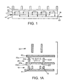
- FIG. 1 is a schematic block diagram of an embodiment of a heat exchanger apparatus.
- FIG. 1A is a diagrammatic exploded cross-sectional view of the heat exchanger of FIG. 1 , illustrating embodiments of the manifold layer, the core structure, the faceplate and the grid.
- FIG. 2 is a schematic plan view of an embodiment of a manifold network of the heat exchanger of FIG. 1 .
- FIG. 3 is a schematic sectional view of an embodiment of a core structure of the heat exchanger apparatus of FIG. 1 .
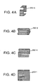
- FIGS. 4A-4D illustrate several alternate embodiments of the finstock conduits of the core structure.
- FIG. 1 is a schematic block diagram of an embodiment of a heat exchanger system that includes a manifold network 10 with an array of plenums arranged in a parallel distribution network which supply fluid for the heat exchanger.
- the heat exchanger includes a core structure 20 that can comprise finstock for example, and a faceplate 40 which seals the assembly.
- the faceplate 40 side of the assembly receives heat from such sources of heat as electronic components.
- the heat sources may be mounted on the faceplate, or in a component supporting "eggcrate" or grid 30 that is thermally coupled to the core structure 20 by the faceplate layer.
- the manifold network 10 distributes a heat exchanger input stream 41 ( FIG. 1 ) of heat exchanger fluid into a plurality of core element conduits 25 ( FIG. 3 ) of the core structure 20.
- the heat exchanger fluid flows from manifold inlet plenums or channels 11 ( FIG. 2 ) through the core element conduits 25 and returns to outlet plenums or channels 13 ( FIG. 2 ) of the manifold network 10 which combines fluid received from the various core elements into a heat exchanger fluid output stream 43 ( FIG. 1 ).
- Each core element conduit can provide for a multiple pass flow of the fluid flowing therein.
- the component support grid 30 can include a plurality of component receiving pockets, and the grid 30 and/or faceplate 40 supports the electronic components or modules that are to be cooled.
- FIG. 1A is a diagrammatic exploded cross-sectional view of the heat exchanger of FIG. 1 , illustrating embodiments of the manifold layer 10, the core structure 20, the faceplate 40 and the grid 30.
- the layer 20 can include a machined layer 20a having numerous cavities 20b. Within each cavity is a high density stamped or machined finstock 20c. Inlet and outlet openings 20d and 20f are located at each end of the finstock, and correspond to locations of the inlet and outlet plenums 11 and 13 of the manifold network 10.
- FIG. 2 is a schematic plan view of an embodiment of a manifold network 10, as viewed at the interface with the core structure 20.
- the manifold network includes an inlet supply plenum 16, and a plurality of inlet channels or plenums 11 having an inlet end 11-1 in fluid communication with the inlet supply plenum 16, that provide heat exchanger fluid to the core structure 20, and a distal end 11-2 which is closed, preventing fluid flow through the distal end.
- the manifold network further includes an outlet or return supply plenum 18 in fluid communication with an outlet end 13-1 of each of a plurality of outlet channels or plenums 13 that receive heat exchanger fluid from the core structure 20.
- the outlet channels 13 have a closed distal end 13-2.
- the input plenums 11 and output plenums 13 can be generally parallel and alternating in an inter-digitated manner, for example.
- the manifold network can also include a plurality of lightening pockets 15 disposed between the inlet and outlet plenums 11, 13 of the manifold network which also serve as thermal isolation pockets. These pockets are relieved areas which reduce the unwanted warming of the inlet fluid in the inlet plenums, thus further ensuring an even mounting temperature.
- the manifold structure can be machined or stamped from a suitable metal or other material.
- heat exchange fluid will be pumped into the heat exchanger inlet plenum 16 through an inlet port 17 ( FIG. 1 ), and the heated fluid from the outlet plenum 18 flows out of the heat exchanger through an outlet port 19 ( FIG. 1 ). Fluid thus flows into the inlet ends of the inlet plenums 11, into the core element conduits of the core structure 20, and then into the outlet plenums 13 and into the outlet return plenum 19.
- FIG. 3 is a schematic diagram of an embodiment of a core structure 20 that comprises a plurality of core element conduits 25, which can comprise finstock (e.g., stamped aluminum) attached to a facesheet, arranged for example in a two-dimensional array.
- Each core element conduit 25 includes an inlet 21 and an outlet 23.
- Each of the inlets 21 is in fluid communication with a corresponding inlet channel 11 of the manifold network, through a hole or opening machined or formed in the top wall of the inlet channel 11 and the structure 20.
- the openings could also be incorporated into the finstock.
- each of the outlets 23 is in fluid communication with a corresponding outlet channel 13 of the manifold network, through a hole or opening formed in the top wall of the outlet channel 13.
- a core element conduit 25 can share an outlet to an outlet plenum 13 with an adjacent core conduit element on one side thereof and/or an inlet from an inlet plenum 11 with an adjacent core conduit element on the other side thereof. Sharing of inlet and outlets in this manner is shown in FIG. 3 , wherein the inlet channels 11 and outlet channels 13 of the manifold structure are shown in phantom.
- the inlets 21 and the outlets 23 can be on the same side of the 2-dimensional array which can be generally planar, for example.
- each core element conduit 25 can be a multi-pass, serpentine-shaped or S-shaped core element conduit formed of a plurality of finstock legs 25a that are serially, fluidically interconnected by turning plenums 25b.
- the finstock legs 25a of the core element conduits 25 have a fin density of at least 50 core elements per inch (fpi).
- the core element conduits 25 can be arranged in linear arrays each formed of a plurality of interconnected core elements 25.
- each linear array can comprise a plurality of interconnected serpentine-shaped or S-shaped core element conduits, each sharing an inlet and/or an outlet with an adjacent core element.
- the core element conduits can be formed of stamped or machined finstock attached to a face sheet 20a ( FIG. 1A ), for example by brazing.
- the core element conduits can be fabricated of one pass finstock 250-1 ( FIG. 4D ), wherein a single leg connects the inlet and outlets for the conduit, or two pass finstock 250-2 ( FIG. 4B ).
- a serpentine three pass core element 250-3 can have relatively wide spacing between the legs, as illustrated in FIG. 4A , or a narrower spacing between the legs, as shown as 250-4 in FIG. 4C .
- the particular configuration of the core element conduits can be designed to meet particular pressure drop, flow balance and heat transfer requirements for a particular application.
- the manifold network thickness and dimensions of the inlet and outlet plenum channels can be chosen such the pressure drop in the manifold layer is much less than the pressure drop in the core structure 20. This provides an even flow distribution over a large range of heat exchanger flow rates. Also, the manifold 10 can be large enough in cross-section to provide proper flow distribution without necessarily using orifices for flow balancing.
- An exemplary embodiment of a heat exchanger provides a high performance and uniform surface temperature heat sink.
- the exemplary embodiment includes a high-density stamped or machined finstock layer mounted above a parallel-flow manifold network.
- Individual fin core elements are located beneath high heat density electrical components mounted on the faceplate layer or eggcrate structure.
- the fin densities are greater than 50 fpi.
- the manifold network is routed between and/or below the fin core elements and thermally isolated to prevent excessive heat influx into the input cooling fluid.
- Cooling fluid enters and leaves the finstock layer of the structure 20 via machined openings 21, 23 ( FIG. 1A ) between the manifold layer and finstock layer.
- the actual openings can be incorporated into the finstock layer itself.
- the fluid flow is split in half, entering two conduits 25 from each inlet hole formed between the manifold layer and finstock layer. Each half of the fluid then goes into a path of high density stamped or machined fin, having a density in excess of 50 fpi in this embodiment.
- the fin density was 86 fpi, with fins 0.060 inch high and fin material which was 0.005 inch thick.
- the fin core elements are serpentine to increase the pressure drop to further ensure proper flow distribution of the entire heat exchanger.
- a top layer 40 a facesheet, can be employed to seal the assembly.
- the facesheet is applied to the assembly side where heat would be inputted from such sources as electronic components attached to the grid 30.
- the entire assembly may be assembled using a process such as brazing. Other assembly processes can alternatively be employed, e.g. diffusion bonding.
- Alternate configurations can be designed in accordance with aspects of the invention, and using a general principle of a parallel distribution system to numerous locations with high density finstock.
- the manifold layer may be incorporated into the finstock layer to reduce the thickness of the assembly.
Landscapes
- Engineering & Computer Science (AREA)
- Physics & Mathematics (AREA)
- Thermal Sciences (AREA)
- Mechanical Engineering (AREA)
- General Engineering & Computer Science (AREA)
- Microelectronics & Electronic Packaging (AREA)
- Heat-Exchange Devices With Radiators And Conduit Assemblies (AREA)
- Cooling Or The Like Of Electrical Apparatus (AREA)
Description
- The subject disclosure is directed generally to heat exchangers, and more particularly to a heat exchanger that can be employed to cool electronics systems such as avionics systems.
- Avionics systems are becoming more complex and providing appropriate cooling can be difficult. Typical heat exchangers used in the avionics industry use low density stamped or machined finstock (pins or pin fins) in the range of 12-30 fins per inch (fpi). These heat exchangers provide poor thermal heat transfer characteristics, yielding unit thermal conductances (UTC) on the order of 0.5 - 2.0 W/sq.-in°C.
-
DE 202 08 106 U1 discloses a cooling device, wherein the part to be cooled is arranged at the upper side of a cooled plate, which lower side is cooled by a cooling fluid that is guided via a distributing element along the cooled plate. The fluid inlet and the fluid outlet of the distributing element are arranged orthogonally to the cooled plate. In particular, the distributing element is divided up into cells, wherein each cell has an individual cooling inlet and a cooling outlet arranged orthogonally to the cooled plate. - A heat exchanger apparatus comprises a two-dimensional array of heat exchanging conduits, wherein each conduit includes an inlet and an outlet, and a manifold for providing heat exchanging fluid to the inputs of the heat exchanging conduits and for receiving heat exchanging fluid from the outputs of the heat exchanging conduits.
- Features and advantages of the disclosure will readily be appreciated by persons skilled in the art from the following detailed description when read in conjunction with the drawing wherein:
-
FIG. 1 is a schematic block diagram of an embodiment of a heat exchanger apparatus. -
FIG. 1A is a diagrammatic exploded cross-sectional view of the heat exchanger ofFIG. 1 , illustrating embodiments of the manifold layer, the core structure, the faceplate and the grid. -
FIG. 2 is a schematic plan view of an embodiment of a manifold network of the heat exchanger ofFIG. 1 . -
FIG. 3 is a schematic sectional view of an embodiment of a core structure of the heat exchanger apparatus ofFIG. 1 . -
FIGS. 4A-4D illustrate several alternate embodiments of the finstock conduits of the core structure. -
FIG. 1 is a schematic block diagram of an embodiment of a heat exchanger system that includes amanifold network 10 with an array of plenums arranged in a parallel distribution network which supply fluid for the heat exchanger. The heat exchanger includes acore structure 20 that can comprise finstock for example, and afaceplate 40 which seals the assembly. Thefaceplate 40 side of the assembly receives heat from such sources of heat as electronic components. The heat sources may be mounted on the faceplate, or in a component supporting "eggcrate" orgrid 30 that is thermally coupled to thecore structure 20 by the faceplate layer. - The
manifold network 10 distributes a heat exchanger input stream 41 (FIG. 1 ) of heat exchanger fluid into a plurality of core element conduits 25 (FIG. 3 ) of thecore structure 20. The heat exchanger fluid flows from manifold inlet plenums or channels 11 (FIG. 2 ) through thecore element conduits 25 and returns to outlet plenums or channels 13 (FIG. 2 ) of themanifold network 10 which combines fluid received from the various core elements into a heat exchanger fluid output stream 43 (FIG. 1 ). Each core element conduit can provide for a multiple pass flow of the fluid flowing therein. In this exemplary embodiment, thecomponent support grid 30 can include a plurality of component receiving pockets, and thegrid 30 and/or faceplate 40 supports the electronic components or modules that are to be cooled. -
FIG. 1A is a diagrammatic exploded cross-sectional view of the heat exchanger ofFIG. 1 , illustrating embodiments of themanifold layer 10, thecore structure 20, thefaceplate 40 and thegrid 30. Thelayer 20 can include amachined layer 20a havingnumerous cavities 20b. Within each cavity is a high density stamped or machined finstock 20c. Inlet andoutlet openings outlet plenums manifold network 10. -
FIG. 2 is a schematic plan view of an embodiment of amanifold network 10, as viewed at the interface with thecore structure 20. The manifold network includes aninlet supply plenum 16, and a plurality of inlet channels orplenums 11 having an inlet end 11-1 in fluid communication with theinlet supply plenum 16, that provide heat exchanger fluid to thecore structure 20, and a distal end 11-2 which is closed, preventing fluid flow through the distal end. The manifold network further includes an outlet orreturn supply plenum 18 in fluid communication with an outlet end 13-1 of each of a plurality of outlet channels orplenums 13 that receive heat exchanger fluid from thecore structure 20. Theoutlet channels 13 have a closed distal end 13-2. Theinput plenums 11 andoutput plenums 13 can be generally parallel and alternating in an inter-digitated manner, for example. - The manifold network can also include a plurality of
lightening pockets 15 disposed between the inlet andoutlet plenums - The manifold structure can be machined or stamped from a suitable metal or other material. In an exemplary application heat exchange fluid will be pumped into the heat
exchanger inlet plenum 16 through an inlet port 17 (FIG. 1 ), and the heated fluid from theoutlet plenum 18 flows out of the heat exchanger through an outlet port 19 (FIG. 1 ). Fluid thus flows into the inlet ends of theinlet plenums 11, into the core element conduits of thecore structure 20, and then into theoutlet plenums 13 and into theoutlet return plenum 19. -
FIG. 3 is a schematic diagram of an embodiment of acore structure 20 that comprises a plurality ofcore element conduits 25, which can comprise finstock (e.g., stamped aluminum) attached to a facesheet, arranged for example in a two-dimensional array. Eachcore element conduit 25 includes aninlet 21 and anoutlet 23. Each of theinlets 21 is in fluid communication with acorresponding inlet channel 11 of the manifold network, through a hole or opening machined or formed in the top wall of theinlet channel 11 and thestructure 20. The openings could also be incorporated into the finstock. Similarly, each of theoutlets 23 is in fluid communication with acorresponding outlet channel 13 of the manifold network, through a hole or opening formed in the top wall of theoutlet channel 13. - A
core element conduit 25 can share an outlet to anoutlet plenum 13 with an adjacent core conduit element on one side thereof and/or an inlet from aninlet plenum 11 with an adjacent core conduit element on the other side thereof. Sharing of inlet and outlets in this manner is shown inFIG. 3 , wherein theinlet channels 11 andoutlet channels 13 of the manifold structure are shown in phantom. Theinlets 21 and theoutlets 23 can be on the same side of the 2-dimensional array which can be generally planar, for example. - In an exemplary embodiment, each
core element conduit 25 can be a multi-pass, serpentine-shaped or S-shaped core element conduit formed of a plurality offinstock legs 25a that are serially, fluidically interconnected by turningplenums 25b. By way of illustrative example, thefinstock legs 25a of thecore element conduits 25 have a fin density of at least 50 core elements per inch (fpi). Thecore element conduits 25 can be arranged in linear arrays each formed of a plurality of interconnectedcore elements 25. For example, each linear array can comprise a plurality of interconnected serpentine-shaped or S-shaped core element conduits, each sharing an inlet and/or an outlet with an adjacent core element. The core element conduits can be formed of stamped or machined finstock attached to aface sheet 20a (FIG. 1A ), for example by brazing. Alternatively, the core element conduits can be fabricated of one pass finstock 250-1 (FIG. 4D ), wherein a single leg connects the inlet and outlets for the conduit, or two pass finstock 250-2 (FIG. 4B ). A serpentine three pass core element 250-3 can have relatively wide spacing between the legs, as illustrated inFIG. 4A , or a narrower spacing between the legs, as shown as 250-4 inFIG. 4C . The particular configuration of the core element conduits can be designed to meet particular pressure drop, flow balance and heat transfer requirements for a particular application. - The manifold network thickness and dimensions of the inlet and outlet plenum channels can be chosen such the pressure drop in the manifold layer is much less than the pressure drop in the
core structure 20. This provides an even flow distribution over a large range of heat exchanger flow rates. Also, the manifold 10 can be large enough in cross-section to provide proper flow distribution without necessarily using orifices for flow balancing. - An exemplary embodiment of a heat exchanger provides a high performance and uniform surface temperature heat sink. The exemplary embodiment includes a high-density stamped or machined finstock layer mounted above a parallel-flow manifold network. Individual fin core elements are located beneath high heat density electrical components mounted on the faceplate layer or eggcrate structure. In the exemplary embodiment, the fin densities are greater than 50 fpi. The manifold network is routed between and/or below the fin core elements and thermally isolated to prevent excessive heat influx into the input cooling fluid.
- Cooling fluid enters and leaves the finstock layer of the
structure 20 via machinedopenings 21, 23 (FIG. 1A ) between the manifold layer and finstock layer. The actual openings can be incorporated into the finstock layer itself. As the cooling fluid enters the finstock layer, in an exemplary embodiment, the fluid flow is split in half, entering twoconduits 25 from each inlet hole formed between the manifold layer and finstock layer. Each half of the fluid then goes into a path of high density stamped or machined fin, having a density in excess of 50 fpi in this embodiment. In one exemplary structure, the fin density was 86 fpi, with fins 0.060 inch high and fin material which was 0.005 inch thick. In an exemplary embodiment, the fin core elements are serpentine to increase the pressure drop to further ensure proper flow distribution of the entire heat exchanger. Atop layer 40, a facesheet, can be employed to seal the assembly. The facesheet is applied to the assembly side where heat would be inputted from such sources as electronic components attached to thegrid 30. The entire assembly may be assembled using a process such as brazing. Other assembly processes can alternatively be employed, e.g. diffusion bonding. - Alternate configurations can be designed in accordance with aspects of the invention, and using a general principle of a parallel distribution system to numerous locations with high density finstock. The manifold layer may be incorporated into the finstock layer to reduce the thickness of the assembly.
- Although the foregoing has been a description and illustration of specific embodiments of the invention, various modifications and changes thereto can be made by persons skilled in the art without departing from the scope and spirit of the invention as defined by the following claims.
Claims (15)
- Heat exchanger apparatus comprising:a two-dimensional array (20) of heat exchanging conduits (25);each conduit having an inlet (21) and an outlet (23);a manifold (10) including a plurality of inlet plenums (11) for providing heat exchanging fluid to the inputs of the heat exchanging conduits, and a plurality of outlet plenums (13) for receiving heat exchanging fluid from the outputs of the heat exchanging conduits, and wherein the inlet plenums (11) and outlet plenums (13) are in fluid communication only through said heat exchanging conduits (25),characterized in that the array (20) is a generally planar finstock layer comprising an array of heat exchanging finstock conduits (25).
- Apparatus according to claim 1, wherein each of the heat exchanging conduits (25) is non-linear.
- Apparatus according to claim 1 or 2, wherein each of the heat exchanging conduits is serpentine.
- Apparatus according to any of claims 1 to 3, wherein each of the heat exchanging conduits includes a plurality of interconnected substantially parallel legs.
- Apparatus according to any preceding claim, wherein the heat exchanging conduits (25) are arranged in linear arrays of heat exchanging conduits.
- Apparatus according to any preceding claim, wherein adjacent heat exchanging conduits (25) share a common outlet (23) to one of said outlet plenums (13).
- Apparatus according to any preceding claim, wherein adjacent heat exchanging conduits (25) share a common inlet (21) to one of said inlet plenums (11).
- Apparatus according to any preceding claim, wherein the heat exchanging conduits (25) are arranged in rows and columns.
- Apparatus according to any preceding claim, wherein each of the heat exchanging conduits (25) comprises a multi-pass finstock element (20c).
- Apparatus according to any preceding claim, wherein the plurality of the heat exchanging conduits (25) includes linear arrays of multi-pass finstock elements (20c).
- Apparatus according to any preceding claim, wherein the heat exchanging conduits (25) comprise finstock elements (20c) of at least about 50 fins per inch.
- Apparatus according to any preceding claim, wherein the inlet plenums (11) and outlet plenums (13) are generally parallel and alternating channels arranged in an inter-digitated arrangement.
- Apparatus according any preceding claim, further comprising a plurality of thermal isolation pockets (15) disposed between the inlet plenums (11) and outlet plenums (13).
- Apparatus according to any preceding claim, wherein the inlet plenums (11) each have an inlet end (11-1) in fluid communication with a supply of heat exchanger fluid, and a closed distal end (11-2).
- Apparatus according to any preceding claim, further comprising a faceplate layer (40), said array (20) of heat exchanging conduits (25) sandwiched between said manifold (10) and said faceplate layer (40).
Applications Claiming Priority (2)
| Application Number | Priority Date | Filing Date | Title |
|---|---|---|---|
| US10/601,385 US7032651B2 (en) | 2003-06-23 | 2003-06-23 | Heat exchanger |
| US601385 | 2003-06-23 |
Publications (3)
| Publication Number | Publication Date |
|---|---|
| EP1492397A2 EP1492397A2 (en) | 2004-12-29 |
| EP1492397A3 EP1492397A3 (en) | 2007-10-03 |
| EP1492397B1 true EP1492397B1 (en) | 2010-12-15 |
Family
ID=33418590
Family Applications (1)
| Application Number | Title | Priority Date | Filing Date |
|---|---|---|---|
| EP04011900A Expired - Lifetime EP1492397B1 (en) | 2003-06-23 | 2004-05-19 | Heat exchanger |
Country Status (3)
| Country | Link |
|---|---|
| US (1) | US7032651B2 (en) |
| EP (1) | EP1492397B1 (en) |
| DE (1) | DE602004030515D1 (en) |
Families Citing this family (31)
| Publication number | Priority date | Publication date | Assignee | Title |
|---|---|---|---|---|
| WO2005088222A1 (en) * | 2004-03-11 | 2005-09-22 | Danfoss Silicon Power Gmbh | A fluid cooling system |
| US20060096738A1 (en) * | 2004-11-05 | 2006-05-11 | Aavid Thermalloy, Llc | Liquid cold plate heat exchanger |
| US7353859B2 (en) * | 2004-11-24 | 2008-04-08 | General Electric Company | Heat sink with microchannel cooling for power devices |
| US7327024B2 (en) * | 2004-11-24 | 2008-02-05 | General Electric Company | Power module, and phase leg assembly |
| US7301770B2 (en) * | 2004-12-10 | 2007-11-27 | International Business Machines Corporation | Cooling apparatus, cooled electronic module, and methods of fabrication thereof employing thermally conductive, wire-bonded pin fins |
| US7201217B2 (en) * | 2005-05-24 | 2007-04-10 | Raytheon Company | Cold plate assembly |
| US7331378B2 (en) * | 2006-01-17 | 2008-02-19 | Delphi Technologies, Inc. | Microchannel heat sink |
| DE102006018709B3 (en) * | 2006-04-20 | 2007-10-11 | Nft Nanofiltertechnik Gmbh | Heat exchanger for cooling electronic component, has two stages arranged consecutively, where each stage has heat exchanging channel and guiding channels that are in flow connection with heat exchanging channels of next stages |
| US7757752B2 (en) * | 2006-05-12 | 2010-07-20 | Seiko Epson Corporation | Heat exchanger, light source apparatus, and projector |
| DE102007022517B4 (en) * | 2007-05-14 | 2010-06-02 | Continental Automotive Gmbh | Heat exchanger for cooling an electronic module |
| US8746330B2 (en) | 2007-08-09 | 2014-06-10 | Coolit Systems Inc. | Fluid heat exchanger configured to provide a split flow |
| US9453691B2 (en) | 2007-08-09 | 2016-09-27 | Coolit Systems, Inc. | Fluid heat exchange systems |
| WO2009034641A1 (en) * | 2007-09-14 | 2009-03-19 | Advantest Corporation | Water jacket |
| US8302671B2 (en) * | 2008-04-29 | 2012-11-06 | Raytheon Company | Scaleable parallel flow micro-channel heat exchanger and method for manufacturing same |
| US8474516B2 (en) * | 2008-08-08 | 2013-07-02 | Mikros Manufacturing, Inc. | Heat exchanger having winding micro-channels |
| US20110226448A1 (en) * | 2008-08-08 | 2011-09-22 | Mikros Manufacturing, Inc. | Heat exchanger having winding channels |
| US8537059B2 (en) * | 2009-11-20 | 2013-09-17 | Raytheon Company | Cooling system for panel array antenna |
| DE102010040582A1 (en) | 2010-09-10 | 2012-03-15 | Continental Automotive Gmbh | Housing for electronic circuit utilized for controlling e.g. occupant protection systems of motor car, has integrated coolant passages formed as cavities in base plates and/or slabs by injection molding method |
| US8783066B2 (en) * | 2011-05-27 | 2014-07-22 | Corning Incorporated | Glass molding system and related apparatus and method |
| WO2014141162A1 (en) | 2013-03-15 | 2014-09-18 | Coolit Systems, Inc. | Sensors, multiplexed communication techniques, and related systems |
| US10365667B2 (en) | 2011-08-11 | 2019-07-30 | Coolit Systems, Inc. | Flow-path controllers and related systems |
| US8717243B2 (en) | 2012-01-11 | 2014-05-06 | Raytheon Company | Low profile cavity backed long slot array antenna with integrated circulators |
| US10415597B2 (en) | 2014-10-27 | 2019-09-17 | Coolit Systems, Inc. | Fluid heat exchange systems |
| US11452243B2 (en) | 2017-10-12 | 2022-09-20 | Coolit Systems, Inc. | Cooling system, controllers and methods |
| DE102018126802B4 (en) * | 2018-10-26 | 2020-08-20 | Rogers Germany Gmbh | Cooling device for a first electronic module and at least one second electronic module, supply device for such a cooling device and method for cooling a first electronic module and at least one second electronic module |
| US11662037B2 (en) | 2019-01-18 | 2023-05-30 | Coolit Systems, Inc. | Fluid flow control valve for fluid flow systems, and methods |
| US11473860B2 (en) | 2019-04-25 | 2022-10-18 | Coolit Systems, Inc. | Cooling module with leak detector and related systems |
| US11395443B2 (en) | 2020-05-11 | 2022-07-19 | Coolit Systems, Inc. | Liquid pumping units, and related systems and methods |
| US11725886B2 (en) | 2021-05-20 | 2023-08-15 | Coolit Systems, Inc. | Modular fluid heat exchange systems |
| US20230011648A1 (en) * | 2021-07-09 | 2023-01-12 | Hamilton Sundstrand Corporation | Monolithic redundant loop cold plate core utilizing adjacent thermal features |
| US12200914B2 (en) | 2022-01-24 | 2025-01-14 | Coolit Systems, Inc. | Smart components, systems and methods for transferring heat |
Family Cites Families (12)
| Publication number | Priority date | Publication date | Assignee | Title |
|---|---|---|---|---|
| US3481393A (en) * | 1968-01-15 | 1969-12-02 | Ibm | Modular cooling system |
| US4072188A (en) * | 1975-07-02 | 1978-02-07 | Honeywell Information Systems Inc. | Fluid cooling systems for electronic systems |
| US4791983A (en) * | 1987-10-13 | 1988-12-20 | Unisys Corporation | Self-aligning liquid-cooling assembly |
| US5166863A (en) * | 1991-07-15 | 1992-11-24 | Amdahl Corporation | Liquid-cooled assembly of heat-generating devices and method for assembling and disassembling |
| US5601141A (en) * | 1992-10-13 | 1997-02-11 | Intelligent Automation Systems, Inc. | High throughput thermal cycler |
| US5811062A (en) * | 1994-07-29 | 1998-09-22 | Battelle Memorial Institute | Microcomponent chemical process sheet architecture |
| DE19911205A1 (en) * | 1999-03-13 | 2000-09-14 | Behr Gmbh & Co | Electronic components cooling device for integration with heat exchanger in motor vehicle, uses rubber layer to compensate for unevennesses of fins or plastic box, and avoids soldering of cooling fins |
| JP2002098454A (en) * | 2000-07-21 | 2002-04-05 | Mitsubishi Materials Corp | Liquid-cooled heat sink and method of manufacturing the same |
| US6462949B1 (en) * | 2000-08-07 | 2002-10-08 | Thermotek, Inc. | Electronic enclosure cooling system |
| US6578626B1 (en) * | 2000-11-21 | 2003-06-17 | Thermal Corp. | Liquid cooled heat exchanger with enhanced flow |
| JP2003051689A (en) * | 2001-08-06 | 2003-02-21 | Toshiba Corp | Heating element cooling unit |
| DE20208106U1 (en) | 2002-05-24 | 2002-10-10 | Danfoss Silicon Power GmbH, 24837 Schleswig | Cooling device for semiconductors with multiple cooling cells |
-
2003
- 2003-06-23 US US10/601,385 patent/US7032651B2/en not_active Expired - Lifetime
-
2004
- 2004-05-19 DE DE602004030515T patent/DE602004030515D1/en not_active Expired - Lifetime
- 2004-05-19 EP EP04011900A patent/EP1492397B1/en not_active Expired - Lifetime
Also Published As
| Publication number | Publication date |
|---|---|
| EP1492397A2 (en) | 2004-12-29 |
| DE602004030515D1 (en) | 2011-01-27 |
| EP1492397A3 (en) | 2007-10-03 |
| US7032651B2 (en) | 2006-04-25 |
| US20040256092A1 (en) | 2004-12-23 |
Similar Documents
| Publication | Publication Date | Title |
|---|---|---|
| EP1492397B1 (en) | Heat exchanger | |
| US5960861A (en) | Cold plate design for thermal management of phase array-radar systems | |
| US7339788B2 (en) | Cooling unit and flow distributing element for use in such unit | |
| EP0151546B1 (en) | Printed circuit board assembly having a liquid-cooling module system | |
| US5088005A (en) | Cold plate for cooling electronics | |
| EP0445309A1 (en) | Fluid heat exchanger for an electronic component | |
| EP1804014B1 (en) | Flow distributing unit and cooling unit | |
| US7201217B2 (en) | Cold plate assembly | |
| US5016090A (en) | Cross-hatch flow distribution and applications thereof | |
| EP1753073B1 (en) | Compliant, internally cooled antenna apparatus and method | |
| US4962444A (en) | Cold chassis for cooling electronic circuit components on an electronic board | |
| CA1247749A (en) | Thermal connector for printed circuit card equipped with electronic components | |
| EP1683404B1 (en) | Flow distributing unit and cooling unit having bypass flow | |
| JPS63138799A (en) | Cooling circuit module | |
| CN113573542B (en) | Compute node tray cooling | |
| EP0410631A2 (en) | Article comprising a stacked array of electronic subassemblies | |
| KR20040050910A (en) | High heat flux single-phase heat exchanger | |
| EP3675615B1 (en) | Flexible cold plate with fluid distribution mechanism | |
| CN112086416B (en) | Micro-channel radiator split-flow integrated cooling device | |
| EP3564992B1 (en) | Fluid-based cooling device for cooling at least two distinct first heat-generating elements of a heat source assembly | |
| GB2226708A (en) | Cooling electronic circuit boards | |
| CN216563103U (en) | Heat radiation assembly, radiator, semiconductor module and vehicle | |
| CN212874481U (en) | Micro-channel radiator shunting integrated cooling device | |
| US6405792B1 (en) | Compact fluid to fluid heat exchanger | |
| CN221447156U (en) | Relieved tooth liquid cooling plate, liquid cooling heat dissipation group, liquid cooling heat dissipation device and liquid cooling heat dissipation server |
Legal Events
| Date | Code | Title | Description |
|---|---|---|---|
| PUAI | Public reference made under article 153(3) epc to a published international application that has entered the european phase |
Free format text: ORIGINAL CODE: 0009012 |
|
| AK | Designated contracting states |
Kind code of ref document: A2 Designated state(s): AT BE BG CH CY CZ DE DK EE ES FI FR GB GR HU IE IT LI LU MC NL PL PT RO SE SI SK TR |
|
| AX | Request for extension of the european patent |
Extension state: AL HR LT LV MK |
|
| PUAL | Search report despatched |
Free format text: ORIGINAL CODE: 0009013 |
|
| AK | Designated contracting states |
Kind code of ref document: A3 Designated state(s): AT BE BG CH CY CZ DE DK EE ES FI FR GB GR HU IE IT LI LU MC NL PL PT RO SE SI SK TR |
|
| AX | Request for extension of the european patent |
Extension state: AL HR LT LV MK |
|
| 17P | Request for examination filed |
Effective date: 20080213 |
|
| AKX | Designation fees paid |
Designated state(s): DE FR GB SE |
|
| 17Q | First examination report despatched |
Effective date: 20100105 |
|
| GRAP | Despatch of communication of intention to grant a patent |
Free format text: ORIGINAL CODE: EPIDOSNIGR1 |
|
| GRAS | Grant fee paid |
Free format text: ORIGINAL CODE: EPIDOSNIGR3 |
|
| GRAA | (expected) grant |
Free format text: ORIGINAL CODE: 0009210 |
|
| AK | Designated contracting states |
Kind code of ref document: B1 Designated state(s): DE FR GB SE |
|
| REG | Reference to a national code |
Ref country code: GB Ref legal event code: FG4D |
|
| REF | Corresponds to: |
Ref document number: 602004030515 Country of ref document: DE Date of ref document: 20110127 Kind code of ref document: P |
|
| REG | Reference to a national code |
Ref country code: SE Ref legal event code: TRGR |
|
| PLBE | No opposition filed within time limit |
Free format text: ORIGINAL CODE: 0009261 |
|
| STAA | Information on the status of an ep patent application or granted ep patent |
Free format text: STATUS: NO OPPOSITION FILED WITHIN TIME LIMIT |
|
| 26N | No opposition filed |
Effective date: 20110916 |
|
| REG | Reference to a national code |
Ref country code: DE Ref legal event code: R097 Ref document number: 602004030515 Country of ref document: DE Effective date: 20110916 |
|
| REG | Reference to a national code |
Ref country code: FR Ref legal event code: PLFP Year of fee payment: 13 |
|
| REG | Reference to a national code |
Ref country code: FR Ref legal event code: PLFP Year of fee payment: 14 |
|
| REG | Reference to a national code |
Ref country code: FR Ref legal event code: PLFP Year of fee payment: 15 |
|
| PGFP | Annual fee paid to national office [announced via postgrant information from national office to epo] |
Ref country code: FR Payment date: 20230420 Year of fee payment: 20 Ref country code: DE Payment date: 20230419 Year of fee payment: 20 |
|
| P01 | Opt-out of the competence of the unified patent court (upc) registered |
Effective date: 20230630 |
|
| PGFP | Annual fee paid to national office [announced via postgrant information from national office to epo] |
Ref country code: SE Payment date: 20230419 Year of fee payment: 20 |
|
| PGFP | Annual fee paid to national office [announced via postgrant information from national office to epo] |
Ref country code: GB Payment date: 20230420 Year of fee payment: 20 |
|
| REG | Reference to a national code |
Ref country code: DE Ref legal event code: R071 Ref document number: 602004030515 Country of ref document: DE |
|
| REG | Reference to a national code |
Ref country code: GB Ref legal event code: PE20 Expiry date: 20240518 |
|
| REG | Reference to a national code |
Ref country code: SE Ref legal event code: EUG |
|
| PG25 | Lapsed in a contracting state [announced via postgrant information from national office to epo] |
Ref country code: GB Free format text: LAPSE BECAUSE OF EXPIRATION OF PROTECTION Effective date: 20240518 |
|
| PG25 | Lapsed in a contracting state [announced via postgrant information from national office to epo] |
Ref country code: GB Free format text: LAPSE BECAUSE OF EXPIRATION OF PROTECTION Effective date: 20240518 |