EP1492394A2 - Laser-produced plasma EUV light source with pre-pulse enhancement - Google Patents
Laser-produced plasma EUV light source with pre-pulse enhancement Download PDFInfo
- Publication number
- EP1492394A2 EP1492394A2 EP20030026665 EP03026665A EP1492394A2 EP 1492394 A2 EP1492394 A2 EP 1492394A2 EP 20030026665 EP20030026665 EP 20030026665 EP 03026665 A EP03026665 A EP 03026665A EP 1492394 A2 EP1492394 A2 EP 1492394A2
- Authority
- EP
- European Patent Office
- Prior art keywords
- pulse
- laser
- main
- main pulse
- euv radiation
- Prior art date
- Legal status (The legal status is an assumption and is not a legal conclusion. Google has not performed a legal analysis and makes no representation as to the accuracy of the status listed.)
- Granted
Links
- 230000036278 prepulse Effects 0.000 title claims abstract description 70
- 230000005855 radiation Effects 0.000 claims abstract description 65
- 239000013077 target material Substances 0.000 claims description 30
- 239000007788 liquid Substances 0.000 claims description 10
- 238000010521 absorption reaction Methods 0.000 abstract description 6
- 230000004907 flux Effects 0.000 abstract description 4
- 230000003111 delayed effect Effects 0.000 abstract description 3
- 210000002381 plasma Anatomy 0.000 description 17
- 238000000034 method Methods 0.000 description 12
- 238000006243 chemical reaction Methods 0.000 description 9
- 230000008569 process Effects 0.000 description 8
- 238000000206 photolithography Methods 0.000 description 7
- 239000007789 gas Substances 0.000 description 6
- 150000002500 ions Chemical class 0.000 description 5
- 230000003287 optical effect Effects 0.000 description 4
- 230000007423 decrease Effects 0.000 description 3
- 238000004519 manufacturing process Methods 0.000 description 3
- 229910052724 xenon Inorganic materials 0.000 description 3
- FHNFHKCVQCLJFQ-UHFFFAOYSA-N xenon atom Chemical compound [Xe] FHNFHKCVQCLJFQ-UHFFFAOYSA-N 0.000 description 3
- XKRFYHLGVUSROY-UHFFFAOYSA-N Argon Chemical compound [Ar] XKRFYHLGVUSROY-UHFFFAOYSA-N 0.000 description 2
- 230000008901 benefit Effects 0.000 description 2
- 230000009467 reduction Effects 0.000 description 2
- 238000000926 separation method Methods 0.000 description 2
- 230000018199 S phase Effects 0.000 description 1
- 238000013019 agitation Methods 0.000 description 1
- 229910052786 argon Inorganic materials 0.000 description 1
- 239000006227 byproduct Substances 0.000 description 1
- 230000008859 change Effects 0.000 description 1
- 239000011248 coating agent Substances 0.000 description 1
- 238000000576 coating method Methods 0.000 description 1
- 238000009833 condensation Methods 0.000 description 1
- 230000005494 condensation Effects 0.000 description 1
- 230000003247 decreasing effect Effects 0.000 description 1
- 230000001934 delay Effects 0.000 description 1
- 239000012530 fluid Substances 0.000 description 1
- 239000012634 fragment Substances 0.000 description 1
- 238000010438 heat treatment Methods 0.000 description 1
- 230000000977 initiatory effect Effects 0.000 description 1
- 238000003780 insertion Methods 0.000 description 1
- 230000037431 insertion Effects 0.000 description 1
- 229910052743 krypton Inorganic materials 0.000 description 1
- DNNSSWSSYDEUBZ-UHFFFAOYSA-N krypton atom Chemical compound [Kr] DNNSSWSSYDEUBZ-UHFFFAOYSA-N 0.000 description 1
- 239000007791 liquid phase Substances 0.000 description 1
- 238000004377 microelectronic Methods 0.000 description 1
- 238000012986 modification Methods 0.000 description 1
- 230000004048 modification Effects 0.000 description 1
- 238000000059 patterning Methods 0.000 description 1
- 238000010587 phase diagram Methods 0.000 description 1
- 229920002120 photoresistant polymer Polymers 0.000 description 1
- 230000002028 premature Effects 0.000 description 1
- 230000001902 propagating effect Effects 0.000 description 1
- 239000007787 solid Substances 0.000 description 1
- 239000000758 substrate Substances 0.000 description 1
- 230000003442 weekly effect Effects 0.000 description 1
Images

Classifications
-
- H—ELECTRICITY
- H05—ELECTRIC TECHNIQUES NOT OTHERWISE PROVIDED FOR
- H05G—X-RAY TECHNIQUE
- H05G2/00—Apparatus or processes specially adapted for producing X-rays, not involving X-ray tubes, e.g. involving generation of a plasma
- H05G2/001—Production of X-ray radiation generated from plasma
- H05G2/008—Production of X-ray radiation generated from plasma involving an energy-carrying beam in the process of plasma generation
- H05G2/0082—Production of X-ray radiation generated from plasma involving an energy-carrying beam in the process of plasma generation the energy-carrying beam being a laser beam
- H05G2/0088—Production of X-ray radiation generated from plasma involving an energy-carrying beam in the process of plasma generation the energy-carrying beam being a laser beam for preconditioning the plasma generating material
-
- H—ELECTRICITY
- H05—ELECTRIC TECHNIQUES NOT OTHERWISE PROVIDED FOR
- H05G—X-RAY TECHNIQUE
- H05G2/00—Apparatus or processes specially adapted for producing X-rays, not involving X-ray tubes, e.g. involving generation of a plasma
- H05G2/001—Production of X-ray radiation generated from plasma
- H05G2/008—Production of X-ray radiation generated from plasma involving an energy-carrying beam in the process of plasma generation
- H05G2/0082—Production of X-ray radiation generated from plasma involving an energy-carrying beam in the process of plasma generation the energy-carrying beam being a laser beam
- H05G2/0084—Control of the laser beam
Definitions
- This invention relates generally to an extreme ultraviolet (EUV) radiation source and, more particularly, to a laser-plasma EUV radiation source that employs a low energy laser pre-pulse immediately preceding a high energy laser main pulse to improve the conversion of laser power to EUV radiation.
- EUV extreme ultraviolet
- Microelectronic integrated circuits are typically patterned on a substrate by a photolithography process, well known to those skilled in the art, where the circuit elements are defined by a light beam propagating through a mask.
- a photolithography process well known to those skilled in the art, where the circuit elements are defined by a light beam propagating through a mask.
- the circuit elements become smaller and more closely spaced together.
- the resolution of the photolithography process increases as the wavelength of the light source decreases to allow smaller integrated circuit elements to be defined.
- the current trend for photolithography light sources is to develop a system that generates light in the extreme ultraviolet (EUV) or soft X-ray wavelengths (13-14 nm).
- EUV extreme ultraviolet
- soft X-ray wavelengths 13-14 nm
- EUV radiation sources are known in the art to generate EUV radiation.
- One of the most popular EUV radiation sources is a laser-plasma, gas condensation source that uses a gas, typically xenon, as a laser plasma target material.
- gases such as argon and krypton, and combinations of gases, are also known for the laser target material.
- the gas is typically cryogenically cooled to a liquid state, and then forced through an orifice or other nozzle opening into a vacuum process chamber as a continuous liquid stream or filament.
- the liquid target material rapidly freezes in the vacuum environment to become a frozen target stream.
- Cryogenically cooled target materials which are gases at room temperature, are desirable because they do not condense on the source optics, and because they produce minimal by-products that have to be evacuated from the process chamber.
- the nozzle is agitated so that the target material emitted from the nozzle forms a stream of liquid droplets having a certain diameter (30-100 ⁇ m) and a predetermined droplet spacing.
- the target stream is irradiated by high-power laser beam pulses, typically from an Nd:YAG laser, that heat the target material to produce a high temperature plasma which emits the EUV radiation.
- the pulse frequency of the laser is application specific and depends on a variety of factors.
- the laser beam pulses must have a certain intensity at the target area in order to provide enough heat to generate the plasma. Typical pulse durations are 5-30 ns, and a typical pulse intensity is in the range of 5 x 10 10 - 5 x 10 12 W/cm 2 .
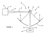
- FIG. 1 is a plan view of an EUV radiation source 10 of the type discussed above including a nozzle 12 having a target material storage chamber 14 that stores a suitable target material, such as xenon, under pressure.
- a heat exchanger or condenser is provided in the chamber 14 that cryogenically cools the target material to a liquid state.
- the liquid target material is forced through a narrowed throat portion or capillary tube 16 of the nozzle 12 to be emitted under pressure as a filament or stream 18 into a vacuum process chamber 26 towards a target area 20.
- the liquid target material will quickly freeze in the vacuum environment to form a solid filament of the target material as it propagates towards the target area 20.
- the vacuum environment in combination with the vapor pressure of the target material will cause the frozen target material to eventually break up into frozen target fragments, depending on the distance that the stream 18 travels and other factors.
- a laser beam 22 from a laser source 24 is directed towards the target area 20 in the process chamber 26 to vaporize the target material filament.
- the heat from the laser beam 22 causes the target material to generate a plasma 30 that radiates EUV radiation 32.
- the EUV radiation 32 is collected by collector optics 34 and is directed to the circuit (not shown) being patterned, or other system using the EUV radiation 32.
- the collector optics 34 can have any shape suitable for the purposes of collecting and directing the radiation 32, such as an elliptical shape. In this design, the laser beam 22 propagates through an opening 36 in the collector optics 34, as shown. Other designs can employ other configurations.
- the throat portion 16 can be vibrated by a suitable device, such as a piezoelectric vibrator, to cause the liquid target material being emitted therefrom to form a stream of droplets.
- a suitable device such as a piezoelectric vibrator
- the frequency of the agitation and the stream velocity determines the size and spacing of the droplets.
- the laser beam 22 may be pulsed to impinge every droplet, or every certain number of droplets.
- Conversion efficiency is a measure of the laser beam energy that is converted into recoverable EUV radiation, i.e., watts of EUV radiation divided by watts of laser power.
- the target stream vapor pressure must be minimized because gaseous target material surrounding the stream tends to absorb the EUV radiation.
- liquid cryogen delivery systems operating near the gas-liquid phase saturation line of the target fluid's phase diagram are typically unable to project a stream of target material significant distances before instabilities in the stream cause it to break up or cause droplets to be formed.
- the distance between the nozzle and the target area must be maximized to keep nozzle heating and condensable source debris to a minimum.
- the pre-pulse is used to improve the absorption of the main pulse.
- the laser pre-pulse forms a weak plasma, but does not have a high enough intensity to generate the wavelength of light of interest.
- the known plasma generating systems using pre-pulses have employed suitable optics that allow the pre-pulse and the main pulse to propagate along the same axis as they impinge the target material.
- Laser produced plasma generation techniques that employ pre-pulses have been shown to increase laser absorption and plasma size, both contributing to enhanced radiation efficiency.
- pre-pulse techniques have not been successfully employed in laser-produced plasma sources that generate EUV radiation.
- an EUV radiation source employs a low energy laser pre-pulse immediately preceding a high energy laser main pulse.
- the pre-pulse generates a weak plasma in the target area that reduces target density and improves laser absorption of the main laser pulse to increase EUV radiation emissions.
- the pre-pulse intensity is not great enough to produce efficient EUV radiation emissions.
- High energy ion flux is reduced by collisions in the localized target vapor cloud generated by the pre-pulse, and thus is less likely to damage source collection optics.
- the low energy pre-pulse arrives at the target area 20-200 ns before the main pulse to provide the maximum EUV radiation generation.
- the EUV radiation intensity can be controlled by decreasing the time period between the pre-pulse and the main pulse.
- the pre-pulse and the main pulse are independent laser beams, separately focused on the target, having an angular separation ⁇ . The angle ⁇ may vary from 0 to 180° to optimize the conversion of the laser energy to EUV radiation emissions.
- the pre-pulse and the main pulse may originate from the same laser source.
- the pre-pulse is split from the main pulse by a suitable beam splitter having the proper beam intensity ratio, and the main pulse is delayed to arrive at the target area after the pre-pulse.
- Figure 1 is a plan view of an EUV radiation source
- Figure 2 is a plan view of an EUV radiation source, employing a laser pre-pulse and a laser main pulse, where the laser pulses are generated by separate laser sources, according to an embodiment of the present invention.
- Figure 3 is a plan view of an EUV radiation source employing a laser pre-pulse and a laser main pulse, where the laser pulses are generated by the same laser source, according to another embodiment of the present invention.
- FIG. 2 is a plan view of an EUV radiation source 50, according to an embodiment of the present invention.
- the EUV radiation source 50 employs a laser pre-pulse beam 52 and a laser main pulse beam 54 that are directed towards a target area 56.
- the durations of the pre-pulse beam 52 and the main pulse beam 54 are within the range of 5 - 30 ns. However, this is by way of a non-limiting example in that any pulse duration suitable for the purposes described herein can be employed.
- a stream 60 of a target material, such as xenon is directed towards the target area 56 from a suitable device 58 to be vaporized and generate the EUV radiation.
- the target stream 60 can be a frozen target filament having a diameter of 20-100 ⁇ m, or any other target suitable for EUV radiation generation, such as a target sheet, target droplets, multiple filaments, etc.
- the pre-pulse beam 52 is generated by a laser source 62, such as an Nd:YAG laser, and is focused by a lens 64 onto the target area 56.
- the main pulse beam 54 is generated by a laser source 68 and focused by a lens 70 onto the target area 56.
- the pre-pulse beam 52 generates a weak plasma 72 in the target area 56 that improves laser absorption of the main pulse beam 54 to increase EUV radiation emissions.
- the pre-pulse beam 52 creates a weakly ionized plasma in the target area 56 that expands from the laser beam focus to provide a preconditioned target that more efficiently absorbs the main pulse 54. It is believed that the pre-pulse beam 52 reduces the density and pressure at the target area 56 so that the main pulse beam 54 is less likely to be reflected from the dense target material, and more likely to be absorbed within the target material to produce the EUV radiation.
- the intensity of the pre-pulse beam 52 at the target area 56 is not great enough to produce efficient EUV radiation emissions.
- Improved absorption of the main beam 54 leads to higher conversion of beam energy to EUV radiation. It has been shown that using the pre-pulse beam 52 increases the energy of the EUV radiation 20% - 30% over those sources that do not employ pre-pulses. Thus, the same amount of EUV radiation can be obtained with smaller laser beam energies, or more EUV radiation can be obtained from the same laser beam energy.
- the laser power of the combined pre-pulse beam 52 and the main beam 54 is not greater, or not significantly greater, than the power of the single laser beam pulses used in the prior art sources.
- the pre-pulse beam 52 is directed at the target area 56 relative to the main pulse beam 54 by an angle ⁇ .
- the angle ⁇ can be any angle between 0 and 180° that would optimize the conversion of the main beam pulse 54 to the EUV radiation.
- the angle ⁇ may be optimized for different applications, such as beam intensities, target materials, etc.
- the intensity of the pre-pulse beam 52 will be about 10% of the intensity of the main pulse beam 54.
- mirrors and the like can be provided to direct the pre-pulse beam 52 and the main pulse beam 54 along the same axis when they impinge the target area 56.
- the pre-pulse beam 52 and the main pulse beam 54 may be linearly polarized in different directions by a suitable polarizer and/or wave plate.
- the pre-pulse beam 52 has an energy of about 40 mJ and a duration of 10 ns
- the main pulse beam 54 has an energy of 700 mJ and a duration of 10 ns
- the angle ⁇ is 30°.
- the prepulse beam 52 has an energy of 10-40 mJ
- the main pulse beam has an energy of 0.1 - 1 J
- the angle ⁇ is 90°.
- the laser sources 62 and 68 are electrically coupled to a controller 74 that provides pulse initiation and timing for the beams 52 and 54.
- the controller 74 can be any controller, microprocessor, etc. suitable for the purposes described herein.
- the pre-pulse beam 52 arrives at the target area 56 just before the main pulse beam 54 to provide the benefits of increased EUV radiation conversion.
- this time delay is 20-200 ns. However, this is by way of a non-limiting example in that other delays and time differences may be suitable for other applications.
- the controller 74 fires the laser 62 first, and then fires the laser 68 the necessary time thereafter.
- the beam 54 is bent by folding optics 76 to provide the desired separation angle ⁇ between the beams 52 and 54.
- the path length from the laser 62 to the target area 56 is the same as the path length from the laser 68 to the target area 56, and the controller 74 provides the timing control. Alternately, the path length from the laser 62 to the target area 56 can be shorter than the path length from the laser 68 to the target area 56 to provide the timing differential.
- the high energy ion flux from the plasma 72 is reduced by collisions in the localized target vapor cloud generated by the pre-pulse beam 52. It is believed that the reduction in high energy ion flux is caused by the less violent reaction with the target material provided by the weekly ionized plasma. This causes a reduction of the yield of highly energetic ions from the plasma 72. These ions, with energies in the small keV range, typically damage sensitive surfaces of the EUV optical components, resulting in loss of reflectance.
- FIG 3 is a plan view of a portion of an EUV radiation source 80, similar to the radiation source 50, where like elements are represented by like reference numerals.
- the radiation source 80 also employs the pre-pulse beam 52 and the main pulse beam 54 separated by the angle ⁇ .
- the laser sources 62 and 68 have been replaced by a single laser source 82 that generates a single laser pulse beam 84.
- the beam 84 is split by a beam splitter 86 that provides the pre-pulse beam 52 and the main pulse beam 54.
- the beam splitter 86 is a well known device that can be designed to select the output intensities of the two beams 52 and 54 to provide the desired beam energies.
- An example of a suitable beam splitter would be a coated mirror, where the coating provides the proper intensity ratio.
- the main pulse beam 54 is delayed by an optical delay device 88 so that it arrives at the target area 56 at the proper time after the pre-pulse beam 52.
- the optical delay device 88 can be any delay device suitable for the purposes described herein, and will generally be a mirror or series of mirrors that provide a longer path length for the main pulse beam 54 than the path length of the pre-pulse beam 52.
- the path length of the main pulse beam 54 is about 20 feet longer than the path length of the pre-pulse beam 52 to provide the proper delay.
- the delay between the beam pulses should be in the range of 20-200 ns.
- the time delay between the pre-pulse beam 52 and the main pulse beam 54 is shorter than 160 ns, then the intensity of the EUV radiation beam will be less than the EUV output intensity in proportion thereto. For example, an 80 ns time delay between the beams 52 and 54 gives about a 20% decrease in the intensity of the EUV radiation output, and a 40 ns delay between the beams 52 and 54 gives about a 30% decrease in the EUV radiation intensity for the same output energy per pulse.
- the EUV pulse energy can be tuned within a range of about 60-100% of the maximum radiation output by varying the prepulse laser beam timing, but keeping a constant laser output energy for the pre-pulse beams 52 and the main pulse beam 54.
- the timing provided by the controller 74 can precisely control the radiation beam output intensity. Accordingly, the amount of EUV radiation intensity delivered to the photolithograph process can be controlled. This greatly relaxes the requirements on pulse-to-pulse stability, and is likely to improve the manufacturing yield in chip production.
Landscapes
- Physics & Mathematics (AREA)
- Optics & Photonics (AREA)
- Engineering & Computer Science (AREA)
- Plasma & Fusion (AREA)
- X-Ray Techniques (AREA)
- Exposure And Positioning Against Photoresist Photosensitive Materials (AREA)
- Plasma Technology (AREA)
- Exposure Of Semiconductors, Excluding Electron Or Ion Beam Exposure (AREA)
Abstract

Description
- This invention relates generally to an extreme ultraviolet (EUV) radiation source and, more particularly, to a laser-plasma EUV radiation source that employs a low energy laser pre-pulse immediately preceding a high energy laser main pulse to improve the conversion of laser power to EUV radiation.
- Microelectronic integrated circuits are typically patterned on a substrate by a photolithography process, well known to those skilled in the art, where the circuit elements are defined by a light beam propagating through a mask. As the state of the art of the photolithography process and integrated circuit architecture becomes more developed, the circuit elements become smaller and more closely spaced together. As the circuit elements become smaller, it is necessary to employ photolithography light sources that generate light beams having shorter wavelengths. In other words, the resolution of the photolithography process increases as the wavelength of the light source decreases to allow smaller integrated circuit elements to be defined. The current trend for photolithography light sources is to develop a system that generates light in the extreme ultraviolet (EUV) or soft X-ray wavelengths (13-14 nm).
- Various devices are known in the art to generate EUV radiation. One of the most popular EUV radiation sources is a laser-plasma, gas condensation source that uses a gas, typically xenon, as a laser plasma target material. Other gases, such as argon and krypton, and combinations of gases, are also known for the laser target material. In the known EUV radiation sources based on laser produced plasmas (LPP), the gas is typically cryogenically cooled to a liquid state, and then forced through an orifice or other nozzle opening into a vacuum process chamber as a continuous liquid stream or filament. The liquid target material rapidly freezes in the vacuum environment to become a frozen target stream. Cryogenically cooled target materials, which are gases at room temperature, are desirable because they do not condense on the source optics, and because they produce minimal by-products that have to be evacuated from the process chamber. In some designs, the nozzle is agitated so that the target material emitted from the nozzle forms a stream of liquid droplets having a certain diameter (30-100 µm) and a predetermined droplet spacing.
- The target stream is irradiated by high-power laser beam pulses, typically from an Nd:YAG laser, that heat the target material to produce a high temperature plasma which emits the EUV radiation. The pulse frequency of the laser is application specific and depends on a variety of factors. The laser beam pulses must have a certain intensity at the target area in order to provide enough heat to generate the plasma. Typical pulse durations are 5-30 ns, and a typical pulse intensity is in the range of 5 x 10¹⁰ - 5 x 10¹² W/cm2.
- Figure 1 is a plan view of an
EUV radiation source 10 of the type discussed above including anozzle 12 having a targetmaterial storage chamber 14 that stores a suitable target material, such as xenon, under pressure. A heat exchanger or condenser is provided in thechamber 14 that cryogenically cools the target material to a liquid state. The liquid target material is forced through a narrowed throat portion orcapillary tube 16 of thenozzle 12 to be emitted under pressure as a filament or stream 18 into avacuum process chamber 26 towards atarget area 20. The liquid target material will quickly freeze in the vacuum environment to form a solid filament of the target material as it propagates towards thetarget area 20. The vacuum environment in combination with the vapor pressure of the target material will cause the frozen target material to eventually break up into frozen target fragments, depending on the distance that thestream 18 travels and other factors. - A
laser beam 22 from alaser source 24 is directed towards thetarget area 20 in theprocess chamber 26 to vaporize the target material filament. The heat from thelaser beam 22 causes the target material to generate aplasma 30 that radiatesEUV radiation 32. The EUVradiation 32 is collected bycollector optics 34 and is directed to the circuit (not shown) being patterned, or other system using theEUV radiation 32. Thecollector optics 34 can have any shape suitable for the purposes of collecting and directing theradiation 32, such as an elliptical shape. In this design, thelaser beam 22 propagates through anopening 36 in thecollector optics 34, as shown. Other designs can employ other configurations. - In an alternate design, the
throat portion 16 can be vibrated by a suitable device, such as a piezoelectric vibrator, to cause the liquid target material being emitted therefrom to form a stream of droplets. The frequency of the agitation and the stream velocity determines the size and spacing of the droplets. If thetarget stream 18 is a series of droplets, thelaser beam 22 may be pulsed to impinge every droplet, or every certain number of droplets. - It is desirable that an EUV radiation source has a good conversion efficiency. Conversion efficiency is a measure of the laser beam energy that is converted into recoverable EUV radiation, i.e., watts of EUV radiation divided by watts of laser power. In order to achieve a good conversion efficiency, the target stream vapor pressure must be minimized because gaseous target material surrounding the stream tends to absorb the EUV radiation. Further, liquid cryogen delivery systems operating near the gas-liquid phase saturation line of the target fluid's phase diagram are typically unable to project a stream of target material significant distances before instabilities in the stream cause it to break up or cause droplets to be formed. Moreover, the distance between the nozzle and the target area must be maximized to keep nozzle heating and condensable source debris to a minimum.
- It is known in the laser-produced plasma art to employ a low energy laser pre-pulse that is incident on the target material prior to a high energy laser main pulse, where the main pulse heats the target material and generates the wavelength of light of interest. The pre-pulse is used to improve the absorption of the main pulse. The laser pre-pulse forms a weak plasma, but does not have a high enough intensity to generate the wavelength of light of interest. The known plasma generating systems using pre-pulses have employed suitable optics that allow the pre-pulse and the main pulse to propagate along the same axis as they impinge the target material. Laser produced plasma generation techniques that employ pre-pulses have been shown to increase laser absorption and plasma size, both contributing to enhanced radiation efficiency. However, pre-pulse techniques have not been successfully employed in laser-produced plasma sources that generate EUV radiation.
- In accordance with the teachings of the present invention, an EUV radiation source is disclosed that employs a low energy laser pre-pulse immediately preceding a high energy laser main pulse. The pre-pulse generates a weak plasma in the target area that reduces target density and improves laser absorption of the main laser pulse to increase EUV radiation emissions. The pre-pulse intensity is not great enough to produce efficient EUV radiation emissions. High energy ion flux is reduced by collisions in the localized target vapor cloud generated by the pre-pulse, and thus is less likely to damage source collection optics.
- In one embodiment, the low energy pre-pulse arrives at the target area 20-200 ns before the main pulse to provide the maximum EUV radiation generation. The EUV radiation intensity can be controlled by decreasing the time period between the pre-pulse and the main pulse. Also, in one embodiment, the pre-pulse and the main pulse are independent laser beams, separately focused on the target, having an angular separation θ. The angle θ may vary from 0 to 180° to optimize the conversion of the laser energy to EUV radiation emissions. In one embodiment, the pre-pulse and the main pulse may originate from the same laser source. The pre-pulse is split from the main pulse by a suitable beam splitter having the proper beam intensity ratio, and the main pulse is delayed to arrive at the target area after the pre-pulse.
- Additional advantages and features of the present invention will become apparent from the following description and appended claims, taken in conjunction with the accompanying drawings.
- Figure 1 is a plan view of an EUV radiation source;
- Figure 2 is a plan view of an EUV radiation source, employing a laser pre-pulse and a laser main pulse, where the laser pulses are generated by separate laser sources, according to an embodiment of the present invention; and
- Figure 3 is a plan view of an EUV radiation source employing a laser pre-pulse and a laser main pulse, where the laser pulses are generated by the same laser source, according to another embodiment of the present invention.
- The following discussion of the embodiments of the present invention directed to an EUV radiation source employing a laser pre-pulse and a laser main pulse is merely exemplary in nature, and is in no way intended to limit the invention or its application or uses. For example, the pre-pulse technique of the invention may be applicable to other radiation source for generating other wavelengths of light other than EUV.
- Figure 2 is a plan view of an
EUV radiation source 50, according to an embodiment of the present invention. As will be discussed in detail below, theEUV radiation source 50 employs alaser pre-pulse beam 52 and a lasermain pulse beam 54 that are directed towards atarget area 56. In one embodiment, the durations of thepre-pulse beam 52 and themain pulse beam 54 are within the range of 5 - 30 ns. However, this is by way of a non-limiting example in that any pulse duration suitable for the purposes described herein can be employed. As discussed above, astream 60 of a target material, such as xenon, is directed towards thetarget area 56 from asuitable device 58 to be vaporized and generate the EUV radiation. Thetarget stream 60 can be a frozen target filament having a diameter of 20-100 µm, or any other target suitable for EUV radiation generation, such as a target sheet, target droplets, multiple filaments, etc. Thepre-pulse beam 52 is generated by alaser source 62, such as an Nd:YAG laser, and is focused by alens 64 onto thetarget area 56. Likewise, themain pulse beam 54 is generated by alaser source 68 and focused by alens 70 onto thetarget area 56. - The
pre-pulse beam 52 generates aweak plasma 72 in thetarget area 56 that improves laser absorption of themain pulse beam 54 to increase EUV radiation emissions. In other words, thepre-pulse beam 52 creates a weakly ionized plasma in thetarget area 56 that expands from the laser beam focus to provide a preconditioned target that more efficiently absorbs themain pulse 54. It is believed that thepre-pulse beam 52 reduces the density and pressure at thetarget area 56 so that themain pulse beam 54 is less likely to be reflected from the dense target material, and more likely to be absorbed within the target material to produce the EUV radiation. The intensity of thepre-pulse beam 52 at thetarget area 56 is not great enough to produce efficient EUV radiation emissions. - Improved absorption of the
main beam 54 leads to higher conversion of beam energy to EUV radiation. It has been shown that using thepre-pulse beam 52 increases the energy of theEUV radiation 20% - 30% over those sources that do not employ pre-pulses. Thus, the same amount of EUV radiation can be obtained with smaller laser beam energies, or more EUV radiation can be obtained from the same laser beam energy. The laser power of the combinedpre-pulse beam 52 and themain beam 54 is not greater, or not significantly greater, than the power of the single laser beam pulses used in the prior art sources. - In this embodiment, the
pre-pulse beam 52 is directed at thetarget area 56 relative to themain pulse beam 54 by an angle θ. The angle θ can be any angle between 0 and 180° that would optimize the conversion of themain beam pulse 54 to the EUV radiation. The angle θ may be optimized for different applications, such as beam intensities, target materials, etc. Typically, the intensity of thepre-pulse beam 52 will be about 10% of the intensity of themain pulse beam 54. Also, mirrors and the like can be provided to direct thepre-pulse beam 52 and themain pulse beam 54 along the same axis when they impinge thetarget area 56. In this embodiment, thepre-pulse beam 52 and themain pulse beam 54 may be linearly polarized in different directions by a suitable polarizer and/or wave plate. In one embodiment, thepre-pulse beam 52 has an energy of about 40 mJ and a duration of 10 ns, themain pulse beam 54 has an energy of 700 mJ and a duration of 10 ns, and the angle θ is 30°. In another embodiment, theprepulse beam 52 has an energy of 10-40 mJ, the main pulse beam has an energy of 0.1 - 1 J, and the angle θ is 90°. - The laser sources 62 and 68 are electrically coupled to a
controller 74 that provides pulse initiation and timing for thebeams controller 74 can be any controller, microprocessor, etc. suitable for the purposes described herein. As discussed herein, thepre-pulse beam 52 arrives at thetarget area 56 just before themain pulse beam 54 to provide the benefits of increased EUV radiation conversion. In one embodiment, this time delay is 20-200 ns. However, this is by way of a non-limiting example in that other delays and time differences may be suitable for other applications. To provide the time delay between thebeams controller 74 fires thelaser 62 first, and then fires thelaser 68 the necessary time thereafter. - In this embodiment, the
beam 54 is bent by foldingoptics 76 to provide the desired separation angle θ between thebeams laser 62 to thetarget area 56 is the same as the path length from thelaser 68 to thetarget area 56, and thecontroller 74 provides the timing control. Alternately, the path length from thelaser 62 to thetarget area 56 can be shorter than the path length from thelaser 68 to thetarget area 56 to provide the timing differential. - Further, it has been shown that the high energy ion flux from the
plasma 72 is reduced by collisions in the localized target vapor cloud generated by thepre-pulse beam 52. It is believed that the reduction in high energy ion flux is caused by the less violent reaction with the target material provided by the weekly ionized plasma. This causes a reduction of the yield of highly energetic ions from theplasma 72. These ions, with energies in the small keV range, typically damage sensitive surfaces of the EUV optical components, resulting in loss of reflectance. - Figure 3 is a plan view of a portion of an
EUV radiation source 80, similar to theradiation source 50, where like elements are represented by like reference numerals. Theradiation source 80 also employs thepre-pulse beam 52 and themain pulse beam 54 separated by the angle θ. In this embodiment, thelaser sources single laser source 82 that generates a singlelaser pulse beam 84. Thebeam 84 is split by abeam splitter 86 that provides thepre-pulse beam 52 and themain pulse beam 54. Thebeam splitter 86 is a well known device that can be designed to select the output intensities of the twobeams - To provide the proper timings, the
main pulse beam 54 is delayed by anoptical delay device 88 so that it arrives at thetarget area 56 at the proper time after thepre-pulse beam 52. Theoptical delay device 88 can be any delay device suitable for the purposes described herein, and will generally be a mirror or series of mirrors that provide a longer path length for themain pulse beam 54 than the path length of thepre-pulse beam 52. In one embodiment, the path length of themain pulse beam 54 is about 20 feet longer than the path length of thepre-pulse beam 52 to provide the proper delay. - As is known in the art, it is sometimes necessary to vary the intensity of the light beam used in photolithography for patterning integrated circuits to precisely control the light dose delivered to the photoresists and masks. For those photolithography systems that employ EUV radiation as the light, it is difficult to vary the EUV radiation output by varying the laser pulse energy that generates the radiation because the laser thermal and optical components are optimized for a specific pulse energy. Deviations from the source design parameters can lead to premature failure of the laser components. Also, methods such as varying the energy input to the laser or insertion of a variable attenuator in the laser beam path to change the EUV radiation intensity are difficult to achieve at the high pulse rates required for volume chip manufacturing. Typically, there is only about 100 microseconds between laser pulses. Therefore, it is desirable to vary the EUV radiation output without varying the drive laser pulse energy.
- As discussed above, to achieve a maximum EUV radiation output from the
pre-pulse beam 52 and themain pulse beam 54, the delay between the beam pulses should be in the range of 20-200 ns. However, if the time delay between thepre-pulse beam 52 and themain pulse beam 54 is shorter than 160 ns, then the intensity of the EUV radiation beam will be less than the EUV output intensity in proportion thereto. For example, an 80 ns time delay between thebeams beams pre-pulse beams 52 and themain pulse beam 54. The timing provided by thecontroller 74 can precisely control the radiation beam output intensity. Accordingly, the amount of EUV radiation intensity delivered to the photolithograph process can be controlled. This greatly relaxes the requirements on pulse-to-pulse stability, and is likely to improve the manufacturing yield in chip production. - The foregoing discussion discloses and describes merely exemplary embodiments of the present invention. One skilled in the art will readily recognize from such discussion and from the accompanying drawings and claims that various changes, modifications and variations can be made therein without departing from the spirit and scope of the invention as defined in the following claims.
Claims (12)
- An extreme (EUV) radiation source for generating EUV radiation, said source comprising:a device for generating at least one stream of a target material, said target material being directed towards a target area; anda system for generating a main pulse laser beam and a pre-pulse laser beam, wherein the main pulse beam and the pre-pulse beam are timed so that the pre-pulse beam arrives at the target area before the main pulse beam, and wherein the pre-pulse beam generates a weakly ionized plasma at the target area and the main pulse beam generates the EUV radiation.
- The source according to claim 1 wherein the system includes a first laser source for generating the main pulse laser beam and a second laser source for generating the pre-pulse beam.
- The source according to claim 1 wherein the system further includes a controller, said controller providing the timing between the main pulse beam and the pre-pulse beam.
- The source according to claim 3 wherein the controller controls the timing between the pre-pulse beam and the main pulse beam to control the intensity of the EUV radiation generated by the source.
- The source according to claim 4 wherein the controller sets the timing between the pre-pulse beam and the main pulse beam to be less than 160 ns to provide a predetermined percentage of the maximum intensity of the EUV radiation.
- The source according to claim 1 wherein the system includes a single laser source for generating laser pulses and a beam splitter for splitting the laser pulses into the main pulse laser beam and the pre-pulse laser beam, said system further including a delay device for delaying the main pulse laser beam relative to the pre-pulse laser beam.
- The source according to claim 1 wherein the main pulse beam and the pre-pulse beam are separated by an angle in the range of 0° - 180° at the target area.
- The source according to claim 7 wherein the angle is about 30°.
- The source according to claim 7 wherein the angle is about 90.
- The source according to claim 1 wherein the pre-pulse beam arrives at the target area in the range of 20-200 ns before the main pulse beam.
- The source according to claim 1 wherein the pre-pulse beam has an energy of about 10 - 40 mJ and the main pulse beam has an energy of about 0.1 to 1 J.
- The source according to claim 1 wherein the at least one stream of the target material is selected from the group consisting of a frozen stream, a liquid stream, multiple streams and target droplets.
Applications Claiming Priority (2)
| Application Number | Priority Date | Filing Date | Title |
|---|---|---|---|
| US10/606,854 US6973164B2 (en) | 2003-06-26 | 2003-06-26 | Laser-produced plasma EUV light source with pre-pulse enhancement |
| US606854 | 2003-06-26 |
Publications (3)
| Publication Number | Publication Date |
|---|---|
| EP1492394A2 true EP1492394A2 (en) | 2004-12-29 |
| EP1492394A3 EP1492394A3 (en) | 2009-12-09 |
| EP1492394B1 EP1492394B1 (en) | 2013-01-02 |
Family
ID=33418701
Family Applications (1)
| Application Number | Title | Priority Date | Filing Date |
|---|---|---|---|
| EP03026665A Expired - Lifetime EP1492394B1 (en) | 2003-06-26 | 2003-11-19 | Laser-produced plasma EUV light source with pre-pulse enhancement |
Country Status (3)
| Country | Link |
|---|---|
| US (1) | US6973164B2 (en) |
| EP (1) | EP1492394B1 (en) |
| JP (1) | JP4712308B2 (en) |
Cited By (9)
| Publication number | Priority date | Publication date | Assignee | Title |
|---|---|---|---|---|
| DE102005014433B3 (en) * | 2005-03-24 | 2006-10-05 | Xtreme Technologies Gmbh | Method and device for the efficient generation of short-wave radiation based on a laser-generated plasma |
| WO2008088488A1 (en) | 2006-12-22 | 2008-07-24 | Cymer, Inc. | Laser produced plasma euv light source |
| US8253123B2 (en) | 2008-12-16 | 2012-08-28 | Koninklijke Philips Electronics N.V. | Method and device for generating EUV radiation or soft X-rays with enhanced efficiency |
| WO2013029906A1 (en) * | 2011-09-02 | 2013-03-07 | Asml Netherlands B.V. | Radiation source |
| WO2013186052A1 (en) * | 2012-06-12 | 2013-12-19 | Trumpf Laser- Und Systemtechnik Gmbh | Euv excitation light source with a laser beam source and a beam guiding device for manipulating the laser beam |
| EP2488002B1 (en) * | 2005-06-29 | 2016-05-04 | ASML Netherlands B.V. | Lpp euv light source drive laser system |
| CN110232982A (en) * | 2013-03-14 | 2019-09-13 | Asml荷兰有限公司 | Target for EUV light source |
| WO2020178244A1 (en) * | 2019-03-07 | 2020-09-10 | Asml Netherlands B.V. | Laser system for source material conditioning in an euv light source |
| WO2025261700A3 (en) * | 2024-06-20 | 2026-03-12 | TRUMPF Lasersystems for Semiconductor Manufacturing SE | Arrangement, installation and method for generating euv radiation or for conducting nuclear fusion, and production method for producing microchips or semiconductor intermediate products for producing microchips |
Families Citing this family (71)
| Publication number | Priority date | Publication date | Assignee | Title |
|---|---|---|---|---|
| US7372056B2 (en) | 2005-06-29 | 2008-05-13 | Cymer, Inc. | LPP EUV plasma source material target delivery system |
| US20060255298A1 (en) * | 2005-02-25 | 2006-11-16 | Cymer, Inc. | Laser produced plasma EUV light source with pre-pulse |
| US7916388B2 (en) * | 2007-12-20 | 2011-03-29 | Cymer, Inc. | Drive laser for EUV light source |
| GB0111204D0 (en) * | 2001-05-08 | 2001-06-27 | Mertek Ltd | High flux,high energy photon source |
| JP2004327213A (en) * | 2003-04-24 | 2004-11-18 | Komatsu Ltd | Debris collection device in EUV light generator |
| FR2871622B1 (en) * | 2004-06-14 | 2008-09-12 | Commissariat Energie Atomique | ULTRAVIOLET LIGHT GENERATING DEVICE AND APPLICATION TO A RADIATION LITHOGRAPHIC SOURCE IN THE EXTREME ULTRAVIOLET |
| US7308007B2 (en) * | 2004-12-23 | 2007-12-11 | Colorado State University Research Foundation | Increased laser output energy and average power at wavelengths below 35 nm |
| WO2006075535A1 (en) * | 2005-01-12 | 2006-07-20 | Nikon Corporation | Laser plasma euv light source, target member, production method for target member, target supplying method, and euv exposure system |
| JP4807560B2 (en) * | 2005-11-04 | 2011-11-02 | 国立大学法人 宮崎大学 | Extreme ultraviolet light generation method and extreme ultraviolet light generation apparatus |
| JP5156192B2 (en) * | 2006-01-24 | 2013-03-06 | ギガフォトン株式会社 | Extreme ultraviolet light source device |
| US7989786B2 (en) * | 2006-03-31 | 2011-08-02 | Energetiq Technology, Inc. | Laser-driven light source |
| US7435982B2 (en) * | 2006-03-31 | 2008-10-14 | Energetiq Technology, Inc. | Laser-driven light source |
| US8536549B2 (en) * | 2006-04-12 | 2013-09-17 | The Regents Of The University Of California | Light source employing laser-produced plasma |
| JP4937643B2 (en) * | 2006-05-29 | 2012-05-23 | 株式会社小松製作所 | Extreme ultraviolet light source device |
| US20110122387A1 (en) * | 2008-05-13 | 2011-05-26 | The Regents Of The University Of California | System and method for light source employing laser-produced plasma |
| KR20100003321A (en) * | 2008-06-24 | 2010-01-08 | 삼성전자주식회사 | Light emitting element, light emitting device comprising the same, and fabricating method of the light emitting element and the light emitting device |
| JP5454881B2 (en) * | 2008-08-29 | 2014-03-26 | ギガフォトン株式会社 | Extreme ultraviolet light source device and method for generating extreme ultraviolet light |
| JP4623192B2 (en) * | 2008-09-29 | 2011-02-02 | ウシオ電機株式会社 | Extreme ultraviolet light source device and extreme ultraviolet light generation method |
| JP5368764B2 (en) * | 2008-10-16 | 2013-12-18 | ギガフォトン株式会社 | Extreme ultraviolet light source device and method of generating extreme ultraviolet light |
| EP2182412A1 (en) * | 2008-11-04 | 2010-05-05 | ASML Netherlands B.V. | Radiation source and lithographic apparatus |
| JP5580032B2 (en) * | 2008-12-26 | 2014-08-27 | ギガフォトン株式会社 | Extreme ultraviolet light source device |
| JP5142217B2 (en) * | 2008-12-27 | 2013-02-13 | ウシオ電機株式会社 | Exposure equipment |
| JP2010205577A (en) * | 2009-03-04 | 2010-09-16 | Ushio Inc | Method of lighting light source device |
| NL2004837A (en) * | 2009-07-09 | 2011-01-10 | Asml Netherlands Bv | Radiation system and lithographic apparatus. |
| JP5612579B2 (en) * | 2009-07-29 | 2014-10-22 | ギガフォトン株式会社 | Extreme ultraviolet light source device, control method of extreme ultraviolet light source device, and recording medium recording the program |
| EP2534672B1 (en) | 2010-02-09 | 2016-06-01 | Energetiq Technology Inc. | Laser-driven light source |
| JP6101741B2 (en) * | 2010-03-29 | 2017-03-22 | ギガフォトン株式会社 | Extreme ultraviolet light generation apparatus and method |
| JP5765759B2 (en) | 2010-03-29 | 2015-08-19 | ギガフォトン株式会社 | Extreme ultraviolet light generation apparatus and method |
| KR101135537B1 (en) * | 2010-07-16 | 2012-04-13 | 삼성모바일디스플레이주식회사 | Laser irradiation apparatus |
| JP2012199512A (en) * | 2011-03-10 | 2012-10-18 | Gigaphoton Inc | Extreme ultraviolet light generation apparatus and extreme ultraviolet light generation method |
| DE102011113681A1 (en) | 2011-09-20 | 2013-03-21 | Heraeus Noblelight Gmbh | Lamp unit for generation of optical radiation, has discharge chamber containing filling gas, ignition source for generating plasma zone within discharge chamber and laser for providing energy to plasma zone by laser beam |
| US9632419B2 (en) * | 2011-09-22 | 2017-04-25 | Asml Netherlands B.V. | Radiation source |
| NL2009372A (en) * | 2011-09-28 | 2013-04-02 | Asml Netherlands Bv | Methods to control euv exposure dose and euv lithographic methods and apparatus using such methods. |
| TWI596384B (en) * | 2012-01-18 | 2017-08-21 | Asml荷蘭公司 | Light source collector element, lithography device and component manufacturing method |
| KR101331493B1 (en) | 2012-05-30 | 2013-11-20 | 한국원자력연구원 | Preparing method for double-layer target with a narrow vacuum gap for the laser induced particle acceleration and double-layer target prepared by the same method |
| WO2014120985A1 (en) * | 2013-01-30 | 2014-08-07 | Kla-Tencor Corporation | Euv light source using cryogenic droplet targets in mask inspection |
| US8872143B2 (en) | 2013-03-14 | 2014-10-28 | Asml Netherlands B.V. | Target for laser produced plasma extreme ultraviolet light source |
| JP6241062B2 (en) | 2013-04-30 | 2017-12-06 | ウシオ電機株式会社 | Extreme ultraviolet light source device |
| IL234727B (en) | 2013-09-20 | 2020-09-30 | Asml Netherlands Bv | Laser-operated light source in an optical system corrected for aberrations and method of designing the optical system |
| IL234729B (en) | 2013-09-20 | 2021-02-28 | Asml Netherlands Bv | Laser-operated light source and method including mode scrambler |
| US9338870B2 (en) * | 2013-12-30 | 2016-05-10 | Asml Netherlands B.V. | Extreme ultraviolet light source |
| US9232623B2 (en) | 2014-01-22 | 2016-01-05 | Asml Netherlands B.V. | Extreme ultraviolet light source |
| US20150262808A1 (en) * | 2014-03-17 | 2015-09-17 | Weifeng Wang | Light Source Driven by Laser |
| JP5962699B2 (en) * | 2014-04-15 | 2016-08-03 | ウシオ電機株式会社 | Energy beam alignment apparatus and alignment method |
| US10186416B2 (en) | 2014-05-15 | 2019-01-22 | Excelitas Technologies Corp. | Apparatus and a method for operating a variable pressure sealed beam lamp |
| US9741553B2 (en) | 2014-05-15 | 2017-08-22 | Excelitas Technologies Corp. | Elliptical and dual parabolic laser driven sealed beam lamps |
| US9748086B2 (en) | 2014-05-15 | 2017-08-29 | Excelitas Technologies Corp. | Laser driven sealed beam lamp |
| US9357625B2 (en) | 2014-07-07 | 2016-05-31 | Asml Netherlands B.V. | Extreme ultraviolet light source |
| JP6434984B2 (en) * | 2014-10-24 | 2018-12-05 | ギガフォトン株式会社 | Extreme ultraviolet light generation system and method for generating extreme ultraviolet light |
| NL2016136A (en) | 2015-02-19 | 2016-09-30 | Asml Netherlands Bv | Radiation Source. |
| US10008378B2 (en) | 2015-05-14 | 2018-06-26 | Excelitas Technologies Corp. | Laser driven sealed beam lamp with improved stability |
| US9576785B2 (en) | 2015-05-14 | 2017-02-21 | Excelitas Technologies Corp. | Electrodeless single CW laser driven xenon lamp |
| US10057973B2 (en) | 2015-05-14 | 2018-08-21 | Excelitas Technologies Corp. | Electrodeless single low power CW laser driven plasma lamp |
| US9538628B1 (en) | 2015-06-11 | 2017-01-03 | Taiwan Semiconductor Manufacturing Co., Ltd. | Method for EUV power improvement with fuel droplet trajectory stabilization |
| US9826615B2 (en) * | 2015-09-22 | 2017-11-21 | Taiwan Semiconductor Manufacturing Co., Ltd. | EUV collector with orientation to avoid contamination |
| US9918375B2 (en) * | 2015-11-16 | 2018-03-13 | Kla-Tencor Corporation | Plasma based light source having a target material coated on a cylindrically-symmetric element |
| US9865447B2 (en) | 2016-03-28 | 2018-01-09 | Kla-Tencor Corporation | High brightness laser-sustained plasma broadband source |
| US20170311429A1 (en) | 2016-04-25 | 2017-10-26 | Asml Netherlands B.V. | Reducing the effect of plasma on an object in an extreme ultraviolet light source |
| US9832852B1 (en) | 2016-11-04 | 2017-11-28 | Asml Netherlands B.V. | EUV LPP source with dose control and laser stabilization using variable width laser pulses |
| CN110692283B (en) * | 2017-05-30 | 2023-09-19 | Asml荷兰有限公司 | radiation source |
| US10109473B1 (en) | 2018-01-26 | 2018-10-23 | Excelitas Technologies Corp. | Mechanically sealed tube for laser sustained plasma lamp and production method for same |
| US10714327B2 (en) * | 2018-03-19 | 2020-07-14 | Kla-Tencor Corporation | System and method for pumping laser sustained plasma and enhancing selected wavelengths of output illumination |
| CN120669483A (en) * | 2019-04-04 | 2025-09-19 | Asml荷兰有限公司 | Radiation system |
| US11650508B2 (en) * | 2020-06-12 | 2023-05-16 | Taiwan Semiconductor Manufacturing Co., Ltd. | Plasma position control for extreme ultraviolet lithography light sources |
| JP7359123B2 (en) | 2020-10-12 | 2023-10-11 | ウシオ電機株式会社 | How to protect extreme ultraviolet light source equipment and receiving plate members |
| US11587781B2 (en) | 2021-05-24 | 2023-02-21 | Hamamatsu Photonics K.K. | Laser-driven light source with electrodeless ignition |
| US12165856B2 (en) | 2022-02-21 | 2024-12-10 | Hamamatsu Photonics K.K. | Inductively coupled plasma light source |
| US12144072B2 (en) | 2022-03-29 | 2024-11-12 | Hamamatsu Photonics K.K. | All-optical laser-driven light source with electrodeless ignition |
| US12156322B2 (en) | 2022-12-08 | 2024-11-26 | Hamamatsu Photonics K.K. | Inductively coupled plasma light source with switched power supply |
| US12578076B2 (en) | 2023-06-05 | 2026-03-17 | Hamamatsu Photonics K.K. | Dual-output laser-driven light source |
| JP2026005509A (en) * | 2024-06-27 | 2026-01-16 | レーザーテック株式会社 | Control device, light source device, control method and program |
Citations (2)
| Publication number | Priority date | Publication date | Assignee | Title |
|---|---|---|---|---|
| US6339634B1 (en) | 1998-10-01 | 2002-01-15 | Nikon Corporation | Soft x-ray light source device |
| DE10149654A1 (en) | 2001-10-08 | 2003-04-10 | Univ Schiller Jena | Synchronizing target time sequence and laser stimulation pulses incident on them for plasma emission stimulation involves controling target and/or pulse generation with target sensor signal |
Family Cites Families (9)
| Publication number | Priority date | Publication date | Assignee | Title |
|---|---|---|---|---|
| US4399539A (en) * | 1982-09-09 | 1983-08-16 | Bell Telephone Laboratories, Incorporated | Auto-ionization pumped anti-Stokes Raman laser |
| US4704718A (en) * | 1985-11-01 | 1987-11-03 | Princeton University | Apparatus and method for generating soft X-ray lasing action in a confined plasma column through the use of a picosecond laser |
| JPH08213192A (en) * | 1995-02-02 | 1996-08-20 | Nippon Telegr & Teleph Corp <Ntt> | X-ray generator and method of generating the same |
| JPH10221499A (en) * | 1997-02-07 | 1998-08-21 | Hitachi Ltd | Laser plasma X-ray source, semiconductor exposure apparatus and semiconductor exposure method using the same |
| WO1999063790A1 (en) * | 1998-05-29 | 1999-12-09 | Nikon Corporation | Laser-excited plasma light source, exposure apparatus and its manufacturing method, and device manufacturing method |
| JP2000111699A (en) * | 1998-10-01 | 2000-04-21 | Nikon Corp | Soft X-ray light source device |
| JP2000299197A (en) * | 1999-04-13 | 2000-10-24 | Agency Of Ind Science & Technol | X-ray generator |
| US6831963B2 (en) * | 2000-10-20 | 2004-12-14 | University Of Central Florida | EUV, XUV, and X-Ray wavelength sources created from laser plasma produced from liquid metal solutions |
| JP2002289397A (en) * | 2001-03-23 | 2002-10-04 | Takayasu Mochizuki | Laser plasma generating method and system thereof |
-
2003
- 2003-06-26 US US10/606,854 patent/US6973164B2/en not_active Expired - Fee Related
- 2003-11-19 EP EP03026665A patent/EP1492394B1/en not_active Expired - Lifetime
-
2004
- 2004-03-29 JP JP2004094892A patent/JP4712308B2/en not_active Expired - Fee Related
Patent Citations (2)
| Publication number | Priority date | Publication date | Assignee | Title |
|---|---|---|---|---|
| US6339634B1 (en) | 1998-10-01 | 2002-01-15 | Nikon Corporation | Soft x-ray light source device |
| DE10149654A1 (en) | 2001-10-08 | 2003-04-10 | Univ Schiller Jena | Synchronizing target time sequence and laser stimulation pulses incident on them for plasma emission stimulation involves controling target and/or pulse generation with target sensor signal |
Cited By (21)
| Publication number | Priority date | Publication date | Assignee | Title |
|---|---|---|---|---|
| DE102005014433B3 (en) * | 2005-03-24 | 2006-10-05 | Xtreme Technologies Gmbh | Method and device for the efficient generation of short-wave radiation based on a laser-generated plasma |
| EP2488002B1 (en) * | 2005-06-29 | 2016-05-04 | ASML Netherlands B.V. | Lpp euv light source drive laser system |
| WO2008088488A1 (en) | 2006-12-22 | 2008-07-24 | Cymer, Inc. | Laser produced plasma euv light source |
| EP2095693A4 (en) * | 2006-12-22 | 2010-11-03 | Cymer Inc | EUV PLASMA LIGHT SOURCE PRODUCED BY LASER |
| US7928416B2 (en) | 2006-12-22 | 2011-04-19 | Cymer, Inc. | Laser produced plasma EUV light source |
| US9713239B2 (en) | 2006-12-22 | 2017-07-18 | Asml Netherlands B.V. | Laser produced plasma EUV light source |
| US8704200B2 (en) | 2006-12-22 | 2014-04-22 | Cymer, Llc | Laser produced plasma EUV light source |
| TWI472266B (en) * | 2008-12-16 | 2015-02-01 | 皇家飛利浦有限公司 | Apparatus and method for generating extreme ultraviolet (EUV) radiation or soft X-ray with enhanced efficiency |
| US8253123B2 (en) | 2008-12-16 | 2012-08-28 | Koninklijke Philips Electronics N.V. | Method and device for generating EUV radiation or soft X-rays with enhanced efficiency |
| WO2013029906A1 (en) * | 2011-09-02 | 2013-03-07 | Asml Netherlands B.V. | Radiation source |
| CN103782662A (en) * | 2011-09-02 | 2014-05-07 | Asml荷兰有限公司 | Radiation source |
| US9366967B2 (en) | 2011-09-02 | 2016-06-14 | Asml Netherlands B.V. | Radiation source |
| CN104472019A (en) * | 2012-06-12 | 2015-03-25 | 通快激光与系统工程有限公司 | EUV excitation light source with laser beam source and beam guidance device for steering the laser beam |
| US9129717B2 (en) | 2012-06-12 | 2015-09-08 | Trumpf Lasersystems For Semiconductor Manufacturing Gmbh | EUV excitation light source with a laser beam source and a beam guide device for manipulating the laser beam |
| CN104472019B (en) * | 2012-06-12 | 2017-02-22 | 通快激光系统半导体制造有限公司 | EUV excitation light source with laser beam source and beam guidance device for steering the laser beam |
| WO2013186052A1 (en) * | 2012-06-12 | 2013-12-19 | Trumpf Laser- Und Systemtechnik Gmbh | Euv excitation light source with a laser beam source and a beam guiding device for manipulating the laser beam |
| CN110232982A (en) * | 2013-03-14 | 2019-09-13 | Asml荷兰有限公司 | Target for EUV light source |
| CN110232982B (en) * | 2013-03-14 | 2023-10-17 | Asml荷兰有限公司 | Targets for extreme ultraviolet light sources |
| WO2020178244A1 (en) * | 2019-03-07 | 2020-09-10 | Asml Netherlands B.V. | Laser system for source material conditioning in an euv light source |
| US12369244B2 (en) | 2019-03-07 | 2025-07-22 | Asml Netherlands B.V. | Laser system for source material conditioning in an EUV light source |
| WO2025261700A3 (en) * | 2024-06-20 | 2026-03-12 | TRUMPF Lasersystems for Semiconductor Manufacturing SE | Arrangement, installation and method for generating euv radiation or for conducting nuclear fusion, and production method for producing microchips or semiconductor intermediate products for producing microchips |
Also Published As
| Publication number | Publication date |
|---|---|
| US20040264512A1 (en) | 2004-12-30 |
| US6973164B2 (en) | 2005-12-06 |
| EP1492394A3 (en) | 2009-12-09 |
| EP1492394B1 (en) | 2013-01-02 |
| JP2005017274A (en) | 2005-01-20 |
| JP4712308B2 (en) | 2011-06-29 |
Similar Documents
| Publication | Publication Date | Title |
|---|---|---|
| US6973164B2 (en) | Laser-produced plasma EUV light source with pre-pulse enhancement | |
| JP7016840B2 (en) | Extreme ultraviolet light source | |
| TWI787648B (en) | Method and system for generating extreme ultraviolet (euv) light and related euv light source | |
| US7075713B2 (en) | High efficiency collector for laser plasma EUV source | |
| JP4874409B2 (en) | Laser plasma extreme ultraviolet radiation source | |
| US9232624B2 (en) | Target for laser produced plasma extreme ultraviolet light source | |
| JP6408578B2 (en) | Extreme ultraviolet light source | |
| US20060255298A1 (en) | Laser produced plasma EUV light source with pre-pulse | |
| US20040129896A1 (en) | Method and device for generating extreme ultravilolet radiation in particular for lithography | |
| EP1255163B1 (en) | High output extreme ultraviolet source | |
| WO2018030122A1 (en) | Extreme ultraviolet light generation method | |
| US6933515B2 (en) | Laser-produced plasma EUV light source with isolated plasma | |
| TWI345931B (en) | Laser produced plasma euv light source with pre-pulse | |
| US6744851B2 (en) | Linear filament array sheet for EUV production |
Legal Events
| Date | Code | Title | Description |
|---|---|---|---|
| PUAI | Public reference made under article 153(3) epc to a published international application that has entered the european phase |
Free format text: ORIGINAL CODE: 0009012 |
|
| AK | Designated contracting states |
Kind code of ref document: A2 Designated state(s): AT BE BG CH CY CZ DE DK EE ES FI FR GB GR HU IE IT LI LU MC NL PT RO SE SI SK TR |
|
| AX | Request for extension of the european patent |
Extension state: AL LT LV MK |
|
| RAP1 | Party data changed (applicant data changed or rights of an application transferred) |
Owner name: UNIVERSITY OF CENTRAL FLORIDA RESEARCH FOUNDATION |
|
| RAP1 | Party data changed (applicant data changed or rights of an application transferred) |
Owner name: UNIVERSITY OF CENTRAL FLORIDA RESEARCH FOUNDATION, |
|
| RAP1 | Party data changed (applicant data changed or rights of an application transferred) |
Owner name: UNIVERSITY OF CENTRAL FLORIDA FOUNDATION, INC. |
|
| PUAL | Search report despatched |
Free format text: ORIGINAL CODE: 0009013 |
|
| AK | Designated contracting states |
Kind code of ref document: A3 Designated state(s): AT BE BG CH CY CZ DE DK EE ES FI FR GB GR HU IE IT LI LU MC NL PT RO SE SI SK TR |
|
| AX | Request for extension of the european patent |
Extension state: AL LT LV MK |
|
| 17P | Request for examination filed |
Effective date: 20100505 |
|
| 17Q | First examination report despatched |
Effective date: 20100601 |
|
| AKX | Designation fees paid |
Designated state(s): DE FR GB SE |
|
| GRAP | Despatch of communication of intention to grant a patent |
Free format text: ORIGINAL CODE: EPIDOSNIGR1 |
|
| GRAJ | Information related to disapproval of communication of intention to grant by the applicant or resumption of examination proceedings by the epo deleted |
Free format text: ORIGINAL CODE: EPIDOSDIGR1 |
|
| GRAS | Grant fee paid |
Free format text: ORIGINAL CODE: EPIDOSNIGR3 |
|
| GRAP | Despatch of communication of intention to grant a patent |
Free format text: ORIGINAL CODE: EPIDOSNIGR1 |
|
| GRAA | (expected) grant |
Free format text: ORIGINAL CODE: 0009210 |
|
| AK | Designated contracting states |
Kind code of ref document: B1 Designated state(s): DE FR GB SE |
|
| REG | Reference to a national code |
Ref country code: GB Ref legal event code: FG4D |
|
| REG | Reference to a national code |
Ref country code: DE Ref legal event code: R096 Ref document number: 60342996 Country of ref document: DE Effective date: 20130314 |
|
| REG | Reference to a national code |
Ref country code: SE Ref legal event code: TRGR |
|
| PLBE | No opposition filed within time limit |
Free format text: ORIGINAL CODE: 0009261 |
|
| STAA | Information on the status of an ep patent application or granted ep patent |
Free format text: STATUS: NO OPPOSITION FILED WITHIN TIME LIMIT |
|
| 26N | No opposition filed |
Effective date: 20131003 |
|
| REG | Reference to a national code |
Ref country code: DE Ref legal event code: R097 Ref document number: 60342996 Country of ref document: DE Effective date: 20131003 |
|
| PGFP | Annual fee paid to national office [announced via postgrant information from national office to epo] |
Ref country code: GB Payment date: 20131127 Year of fee payment: 11 Ref country code: SE Payment date: 20131127 Year of fee payment: 11 Ref country code: FR Payment date: 20131118 Year of fee payment: 11 Ref country code: DE Payment date: 20131127 Year of fee payment: 11 |
|
| REG | Reference to a national code |
Ref country code: DE Ref legal event code: R119 Ref document number: 60342996 Country of ref document: DE |
|
| REG | Reference to a national code |
Ref country code: SE Ref legal event code: EUG |
|
| GBPC | Gb: european patent ceased through non-payment of renewal fee |
Effective date: 20141119 |
|
| PG25 | Lapsed in a contracting state [announced via postgrant information from national office to epo] |
Ref country code: SE Free format text: LAPSE BECAUSE OF NON-PAYMENT OF DUE FEES Effective date: 20141120 |
|
| REG | Reference to a national code |
Ref country code: FR Ref legal event code: ST Effective date: 20150731 |
|
| PG25 | Lapsed in a contracting state [announced via postgrant information from national office to epo] |
Ref country code: GB Free format text: LAPSE BECAUSE OF NON-PAYMENT OF DUE FEES Effective date: 20141119 Ref country code: DE Free format text: LAPSE BECAUSE OF NON-PAYMENT OF DUE FEES Effective date: 20150602 |
|
| PG25 | Lapsed in a contracting state [announced via postgrant information from national office to epo] |
Ref country code: FR Free format text: LAPSE BECAUSE OF NON-PAYMENT OF DUE FEES Effective date: 20141201 |