EP1492383A1 - Process for producing a hearing device and hearing device - Google Patents
Process for producing a hearing device and hearing device Download PDFInfo
- Publication number
- EP1492383A1 EP1492383A1 EP04020809A EP04020809A EP1492383A1 EP 1492383 A1 EP1492383 A1 EP 1492383A1 EP 04020809 A EP04020809 A EP 04020809A EP 04020809 A EP04020809 A EP 04020809A EP 1492383 A1 EP1492383 A1 EP 1492383A1
- Authority
- EP
- European Patent Office
- Prior art keywords
- housing
- hearing aid
- injection molding
- parts
- hearing device
- Prior art date
- Legal status (The legal status is an assumption and is not a legal conclusion. Google has not performed a legal analysis and makes no representation as to the accuracy of the status listed.)
- Granted
Links
Images
Classifications
-
- H—ELECTRICITY
- H04—ELECTRIC COMMUNICATION TECHNIQUE
- H04R—LOUDSPEAKERS, MICROPHONES, GRAMOPHONE PICK-UPS OR LIKE ACOUSTIC ELECTROMECHANICAL TRANSDUCERS; DEAF-AID SETS; PUBLIC ADDRESS SYSTEMS
- H04R25/00—Deaf-aid sets, i.e. electro-acoustic or electro-mechanical hearing aids; Electric tinnitus maskers providing an auditory perception
- H04R25/65—Housing parts, e.g. shells, tips or moulds, or their manufacture
- H04R25/658—Manufacture of housing parts
-
- B—PERFORMING OPERATIONS; TRANSPORTING
- B29—WORKING OF PLASTICS; WORKING OF SUBSTANCES IN A PLASTIC STATE IN GENERAL
- B29C—SHAPING OR JOINING OF PLASTICS; SHAPING OF MATERIAL IN A PLASTIC STATE, NOT OTHERWISE PROVIDED FOR; AFTER-TREATMENT OF THE SHAPED PRODUCTS, e.g. REPAIRING
- B29C45/00—Injection moulding, i.e. forcing the required volume of moulding material through a nozzle into a closed mould; Apparatus therefor
- B29C45/16—Making multilayered or multicoloured articles
- B29C45/1676—Making multilayered or multicoloured articles using a soft material and a rigid material, e.g. making articles with a sealing part
-
- H—ELECTRICITY
- H04—ELECTRIC COMMUNICATION TECHNIQUE
- H04R—LOUDSPEAKERS, MICROPHONES, GRAMOPHONE PICK-UPS OR LIKE ACOUSTIC ELECTROMECHANICAL TRANSDUCERS; DEAF-AID SETS; PUBLIC ADDRESS SYSTEMS
- H04R25/00—Deaf-aid sets, i.e. electro-acoustic or electro-mechanical hearing aids; Electric tinnitus maskers providing an auditory perception
- H04R25/65—Housing parts, e.g. shells, tips or moulds, or their manufacture
-
- B—PERFORMING OPERATIONS; TRANSPORTING
- B29—WORKING OF PLASTICS; WORKING OF SUBSTANCES IN A PLASTIC STATE IN GENERAL
- B29C—SHAPING OR JOINING OF PLASTICS; SHAPING OF MATERIAL IN A PLASTIC STATE, NOT OTHERWISE PROVIDED FOR; AFTER-TREATMENT OF THE SHAPED PRODUCTS, e.g. REPAIRING
- B29C45/00—Injection moulding, i.e. forcing the required volume of moulding material through a nozzle into a closed mould; Apparatus therefor
- B29C45/16—Making multilayered or multicoloured articles
- B29C45/1671—Making multilayered or multicoloured articles with an insert
- B29C2045/1673—Making multilayered or multicoloured articles with an insert injecting the first layer, then feeding the insert, then injecting the second layer
-
- B—PERFORMING OPERATIONS; TRANSPORTING
- B29—WORKING OF PLASTICS; WORKING OF SUBSTANCES IN A PLASTIC STATE IN GENERAL
- B29L—INDEXING SCHEME ASSOCIATED WITH SUBCLASS B29C, RELATING TO PARTICULAR ARTICLES
- B29L2031/00—Other particular articles
- B29L2031/26—Sealing devices, e.g. packaging for pistons or pipe joints
- B29L2031/265—Packings, Gaskets
-
- B—PERFORMING OPERATIONS; TRANSPORTING
- B29—WORKING OF PLASTICS; WORKING OF SUBSTANCES IN A PLASTIC STATE IN GENERAL
- B29L—INDEXING SCHEME ASSOCIATED WITH SUBCLASS B29C, RELATING TO PARTICULAR ARTICLES
- B29L2031/00—Other particular articles
- B29L2031/56—Stoppers or lids for bottles, jars, or the like, e.g. closures
- B29L2031/565—Stoppers or lids for bottles, jars, or the like, e.g. closures for containers
Definitions
- the present invention relates to a method according to the preamble of claim 1 and a hearing aid according to that of claim 9.
- a part of a first material component is made and at least partially overmolded with a second, different material component, which is built on the first part of the second of different material. It is possible to use all sprayable thermoplastic materials, in particular also for the overmoulding method, but also specifically non-connectable further materials.
- the hearing aid housing used, so for example, a shell of a clam shell housing, so it can with the two- or multi-component injection molding further impact parts, in particular seals , eg for tightly uniting with the second housing shell and / or impact-absorbing recesses for installing, delicate device component and / or other active hearing aid components, such as acoustic conductors are grown directly.
- At least one intended seal is basically constructed on the inventive method of preferred embodiment in connection with the two-component or multi-component injection molding technique, together with a further part directly adjacent to the seal, for example and preferably a housing part or a through the housing projecting control element or another hearing aid part, which is to be sealed for each particular accurate.
- the acoustic conductor on the output side of the electrical-mechanical transducer, which acoustic conductor is usually designed as a plastic tube, using the mentioned injection molding method, be it directly together with a housing section. or is this, for example with an elastic form-fitting sealing inserting into a housing receptacle mounting part.
- an acoustic conductor on the input side of the acoustic-electric hearing device converter in the aforementioned injection molding technology, for example, again together with a section of the hearing device housing or with a specifically designed, for example, sealing , elastic mounting part.
- recordings for hearing aid components or parts are made in the mentioned injection molding process, either together with housing lots and / or together with other, directly adjacent to them components.
- predetermined surface areas are produced on the outside of the housing together with the housing - but of other material - in the mentioned injection molding, for example, for design reasons and / or to feel the keys on the housing arranged control organs alone with the fingers to facilitate.
- a hearing aid according to the invention is distinguished by the characteristic of claim 9, preferred embodiments according to claims 10 to 16.
- the embodiments given in the introduction to the description open up a large number of possibilities by combining processing in a two- or multi-component injection molding process, in particular by overmolding, two or more of the components to be provided to save space and to assemble together as an integral part. Nevertheless, with reference to some schematic examples, preferred modes of use of the mentioned Injection molding can be explained. On the actual technology of two- or multi-component injection molding is not discussed, because this is, as mentioned, from the general components, especially from the plastic molding and injection molding technology well known.
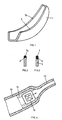
- Fig. 1 the shell 1 of a hearing aid housing, such as an outer ear hearing aid, is shown schematically and in perspective. Along its end faces 3, it is to be assembled with further housing parts in such a way that its interior space is tightly sealed along these end faces 3. Conventionally, this is achieved in that according to Figure 3 in the region of the end faces 3 positioning and Garrungsvorlochept, as shown, for example, grooves are incorporated into the wall of the housing part 1, in which again, manually, a seal 7 is mounted.
- a seal 7a is now sprayed directly onto the aforementioned housing shell 1 or the end face 3, by means of two-component overmoulding injection molding.
- the material of the actual housing part wall satisfies the requirements to be imposed on the housing with respect to stability, etc., while the material of the overmolding sprayed secondary component satisfies the requirements to be imposed on the seal 7a.
- the sealing portion 7a can be dimensioned exactly as it meets the sealing requirements, as well as the wall of the housing section 1 only on criteria that are to be placed on the housing, dimensioned and shaped.
- FIG. 4 shows schematically how, for example, on a hearing aid housing 10 on the one hand, according to the invention, an acoustic conductor 13 is grown, for example on the output side of a mounted in the hearing aid, electro-mechanical transducer or, in Analogy, on the input side of a hearing aid provided on the acoustic-electrical transducer (not shown).
- an elastic, resilient receiving block 15 can be integrated in the housing 10 for the converter unit 12.
- Housing 10 and acoustic conductor 13 and / or housing 10 and receiving block 15 or all three, housing 10, receiving block 15 and acoustic conductor 13 are manufactured as a part in a two- or three-component injection molding.
- a material is selected as the material of the housing 10 or the wall in the usual manner, which satisfies the requirements to be placed on the housing, as a material for the acoustic conductor 13, for example, a material which, for example, for the outer ear device, biocompatible is, and it is selected as the material for the receiving block 15, a material that meets the shock and shock absorption and mounting of the transducer 12 in this respect requirements to be made. It is also readily possible, for example, to choose the material of the block 15 electrically conductive, for example, the transducer 12 should be electrically shielded.
- a first part for example, in turn, a wall of a housing part 10 shown, with a passage opening 17, through which an operating member 19, as a switch, a control element 25 of the hearing device, penetrates.
- an operating member 19 as a switch
- a control element 25 of the hearing device penetrates.
- elastic optionally sealing parts 21 are molded, and optionally also a receptacle 23 for resilient, rich fixation of the unit 25 an optimally space-saving installation of the unit 25 allows.
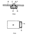
- a receptacle 32 for the corresponding positioning and holding a other aggregates 34 is grown with the aforementioned two- or multi-component injection molding, which in turn allows an optimally small-sized assembly with high packing density.
- a seal 7a which only has to satisfy the sealing requirements can be made substantially smaller and thinner if integrally formed on the part 1 than if It must be separately prepared as a seal 7 and then, for example manually, must be mounted on the corresponding end faces of the part 1, this by gluing, plugging or the like.
- the precision with which the sealing part 7a directly to the end face 3 forming wall of the part can be grown, with the same dimensioning by assembling separate parts is hardly possible or only with great effort.
Landscapes
- Engineering & Computer Science (AREA)
- Manufacturing & Machinery (AREA)
- Health & Medical Sciences (AREA)
- General Health & Medical Sciences (AREA)
- Neurosurgery (AREA)
- Otolaryngology (AREA)
- Physics & Mathematics (AREA)
- Acoustics & Sound (AREA)
- Signal Processing (AREA)
- Mechanical Engineering (AREA)
- Injection Moulding Of Plastics Or The Like (AREA)
- Moulds For Moulding Plastics Or The Like (AREA)
- Casings For Electric Apparatus (AREA)
- Sealing Material Composition (AREA)
Abstract
Description
Die vorliegende Erfindung betrifft ein Verfahren nach dem Oberbegriff von Anspruch 1 sowie ein Hörgerät nach demjenigen von Anspruch 9.The present invention relates to a method according to the preamble of claim 1 and a hearing aid according to that of claim 9.
Zwei- oder Mehrkomponenten-Spritzgiessverfahren sind aus der Kunststoff-Verarbeitungstechnik bekannt. Es kann beispielsweise verwiesen werden auf Ch. Jaroschek "Das Mehrkomponenten-Spritzgiessverfahren" Swiss Plastics 19 (1997) Nr. 12 oder auf U. Stenglin "Hart/Weich-Verbindungen und anwendungsbezogene Modifizierbarkeit von TPE-S (SEBS/SEPS)", Swiss Plastics 20 (1998) Nr. 3. Darin sind die Vorteile von Zwei- oder Mehrkomponenten-Spritzgiessverfahren erläutert, nämlich bezüglich Werkzeugkosten, Personalkosten, Maschinenkosten und Materialkosten. Die erwähnten Verfahren werden grundsätzlich in Sandwich-Spritzgiessverfahren und in Overmoulding-Verfahren kategorisiert. Im vorliegenden Fall interessiert, wenn auch nicht ausschliesslich so doch primär, das erwähnte Overmoulding-Verfahren. Dabei wird ein Teil aus einer ersten Materialkomponente gefertigt und mindestens abschnittsweise mit einer zweiten, unterschiedlichen Materialkomponente überspritzt, womit an den ersten Teil der Zweite aus unterschiedlichem Material, aufgebaut wird. Es lassen sich alle spritzfähigen Thermoplast-Werkstoffe, insbesondere auch für das Overmoulding-Verfahren, einsetzen, aber auch ganz gezielt nicht verbindbare weitere Materialien.Two- or multi-component injection molding processes are known from the plastics processing technology. For example, reference may be made to Ch. Jaroschek "The Multi-component Injection Molding Process" Swiss Plastics 19 (1997) No. 12 or to U. Stenglin "Hard / Soft Compounds and Application Modifiability of TPE-S (SEBS / SEPS)", Swiss Plastics 20 (1998) No. 3. It explains the advantages of two- or multi-component injection molding processes, namely tooling costs, labor costs, machine costs and material costs. The mentioned methods are basically categorized in sandwich injection molding and in overmoulding processes. In the present case, although not exclusively so primarily, the mentioned overmoulding process is of interest. In this case, a part of a first material component is made and at least partially overmolded with a second, different material component, which is built on the first part of the second of different material. It is possible to use all sprayable thermoplastic materials, in particular also for the overmoulding method, but also specifically non-connectable further materials.
Selbstverständlich sind auch bei der Hörgeräte-Produktion die oben erwähnten Kosten wichtige Produktionsfaktoren. Hinzu kommt aber bei der Hörgeräte-Fertigung grundsätzlich das Platzproblem, indem es ein permanentes Bedürfnis der erwähnten Branche ist, möglichst platzsparend zu bauen.Of course, the above-mentioned costs are also important production factors in hearing aid production. In addition, however, there is basically the space problem in hearing aid production in that it is a permanent need of the mentioned industry to build as space-saving as possible.
Es ist Aufgabe der vorliegenden Erfindung, ein Fertigungsverfahren vorzuschlagen, und entsprechend ein daraus resultierendes Hörgerät, welches Verfahren eine signifikante Erhöhung der Baudichte, an Hörgeräten erlaubt.It is an object of the present invention to propose a manufacturing method, and accordingly a resulting hearing aid, which method allows a significant increase in the density of hearing aids.
Zu diesem Zweck wird am erwähnten Verfahren vorgeschlagen, mindestens zwei der am Hörgerät zu assemblierenden Teile in Zweioder Mehrkomponenten-Spritzgiesstechnik zu fertigen und gemeinsam zu assemblieren. Selbstverständlich ist der dabei sich gegebenenfalls einstellende Vorteil der Reduktion obgenannter Kosten hoch willkommen, wesentlicher ist aber, dass durch Einsatz des erwähnten Verfahrens das für die Hörgeräte-Bautechnik essentielle Kriterium, die Erhöhung der Komponentendichte pro cm3 zur Verfügung stehenden Platzes erreicht wird.For this purpose, it is proposed in the mentioned method to manufacture and assemble together at least two of the parts to be assembled on the hearing device in two-component or multi-component injection molding technology. Of course, the case, where appropriate, adjusting advantage of reducing obgenannter cost highly welcome, but essential is that the essential for hearing aid structural engineering criteria, increasing the component density per cm3 available space is achieved by using the aforementioned method.
Wird gemäss einer bevorzugten Ausführungsform des erfindungsgemässen Verfahrens, als einer der Teile, mindestens eine Partie des Hörgeräte-Gehäuses eingesetzt, also beispielsweise die eine Schale eines zweischaligen Gehäuses, so können daran mit dem Zwei- oder Mehrkomponenten-Spritzgiessverfahren weitere Wirkungs-Teile, insbesondere Dichtungen, z.B. zum dichten Vereinigen mit der zweiten Gehäuseschale und/oder schlagdämpfende Aufnehmungen für einzubauende, heikle Gerätekomponente und/oder weitere aktive Hörgeräte-Komponenten, wie akustische Leiter, direkt angebaut werden. Grundsätzlich ergibt sich dadurch die Möglichkeit, Verbindungselemente zwischen den erwähnten Teilen, die bei herkömmlicher Bauweise notwendig sind, wegzulassen bzw. solche Teile nur gerade so voluminös zu bauen als dies funktionsnotwenig ist ohne aber irgendwelche Verbindungspartien, wie Nuten und Stege, vorsehen zu müssen.If according to a preferred embodiment of the inventive method, as one of the parts, at least a portion of the hearing aid housing used, so for example, a shell of a clam shell housing, so it can with the two- or multi-component injection molding further impact parts, in particular seals , eg for tightly uniting with the second housing shell and / or impact-absorbing recesses for installing, delicate device component and / or other active hearing aid components, such as acoustic conductors are grown directly. Basically, this results in the possibility of eliminating fasteners between the mentioned parts, which are necessary in conventional construction, or to build such parts just as voluminous as this is not functional without having to provide any connecting parts, such as grooves and lands.
Wie erwähnt wird am erfindungsgemässen Verfahren bevorzugter Ausführungsform grundsätzlich mindestens eine vorgesehene Dichtung im Zusammenhang mit der Zwei- oder Mehrkomponentenspritztechnik aufgebaut, gemeinsam mit einem weiteren, an die Dichtung unmittelbar angrenzenden Teil, so beispielsweise und vorzugsweise einem Gehäuseteil oder einem durch das Gehäuse durchragenden Bedienungsorgan oder einem weiteren Hörgeräteteil, das für sich besonderes akkurat zu dichten ist.As mentioned above, at least one intended seal is basically constructed on the inventive method of preferred embodiment in connection with the two-component or multi-component injection molding technique, together with a further part directly adjacent to the seal, for example and preferably a housing part or a through the housing projecting control element or another hearing aid part, which is to be sealed for each particular accurate.
In einer weiteren bevorzugten Ausführungsform des Herstellungsverfahrens, insbesondere für Aussenohr-Hörgeräte, wird vorgeschlagen den akustischen Leiter ausgangsseitig des elektrisch-mechanischen Wandlers, welcher akustische Leiter üblicherweise als Kunststoffrohr ausgebildet ist, mit dem erwähnten Spritzgiessverfahren zu fertigen, sei dies gemeinsam direkt mit einer Gehäusepartie, oder sei dies z.B. mit einem elastischen formschlüssig dichtenden in eine Gehäuseaufnahme einzulegenden Montageteil.In a further preferred embodiment of the production method, in particular for outer-ear hearing aids, it is proposed to manufacture the acoustic conductor on the output side of the electrical-mechanical transducer, which acoustic conductor is usually designed as a plastic tube, using the mentioned injection molding method, be it directly together with a housing section. or is this, for example with an elastic form-fitting sealing inserting into a housing receptacle mounting part.
In einer weiteren bevorzugten Ausführungsform des erwähnten Verfahrens wird vorgeschlagen einen akustischen Leiter eingangsseitig des akustisch-elektrischen Hörgeräte-Wandlers, in der erwähnten Spritzgiesstechnik zu fertigen, sei dies, beispielsweise wiederum gemeinsam mit einer Partie des Hörgeräte-Gehäuses oder mit einem spezifisch ausgelegten, beispielsweise dichtenden, elastischen Montageteil. In weiteren Ausführungsformen des erfindungsgemässen Verfahrens, die selbstverständlich je einzeln oder in Kombination mit weiteren, bevorzugten Ausführungsformen einsetzbar sind, werden Aufnahmen für Hörgeräte-Komponenten bzw. -Teile im erwähnten Spritzgiessverfahren gefertigt, sei dies, gemeinsam mit Gehäuse-Partien und/oder gemeinsam mit weiteren, unmittelbar an sie angrenzenden Bauteilen.In a further preferred embodiment of the mentioned method, it is proposed to manufacture an acoustic conductor on the input side of the acoustic-electric hearing device converter in the aforementioned injection molding technology, for example, again together with a section of the hearing device housing or with a specifically designed, for example, sealing , elastic mounting part. In further embodiments of the inventive method, which are of course each used individually or in combination with other preferred embodiments, recordings for hearing aid components or parts are made in the mentioned injection molding process, either together with housing lots and / or together with other, directly adjacent to them components.
In einer weiteren, bevorzugten Ausführungsform werden auf der Aussenseite des Gehäuses vorgegebene Flächenbereiche gemeinsam mit dem Gehäuse - aber aus anderem Material - im erwähnten Spritzgiessverfahren gefertigt, z.B. aus Designgründen und/oder um das Ertasten am Gehäuse angeordneter Bedienungsorgane allein mit den Fingern, zu erleichtern.In a further preferred embodiment, predetermined surface areas are produced on the outside of the housing together with the housing - but of other material - in the mentioned injection molding, for example, for design reasons and / or to feel the keys on the housing arranged control organs alone with the fingers to facilitate.
Ein erfindungsgemässes Hörgerät zeichnet sich nach dem Kennzeichen von Anspruch 9 aus, bevorzugte Ausführungsformen nach den Ansprüchen 10 bis 16.A hearing aid according to the invention is distinguished by the characteristic of claim 9, preferred embodiments according to
Die Erfindung wird anschliessend beispielsweise anhand von Figuren erläutert. Es zeigen:
- Fig. 1 schematisch eine Partie eines Hörgeräte-Gehäuses in perspektivischer Darstellung mit erfindungsgemäss angebauter Dichtung.
- Fig. 2 ein Querschnitt durch einen Teil des Gehäuses nach Fig. 1 mit der erfindungsgemäss aufgebauten Dichtung.
- Fig. 3 einen Querschnitt durch die Gehäusewandung eines nach herkömmlichem Vorgehen aufgebauten Hörgerätes mit assemblierter Dichtung.
- Fig. 4 schematisch einen Querschnitt durch einen Teil eines Hörgeräte-Gehäuses mit erfindungsgemäss angebautem akustischem Leiter und/oder Aufnahme für ein Modul.
- Fig. 5 schematisch einen Querschnitt durch einen Gehäusewandungsabschnitt mit Bedienungseinheit und erfindungsgemäss aufgebauter Durchführung und Einheitshalterung.
- Fig. 6 schematisch und prinzipiell das erfindungsgemässe Verbinden zweier Hörgerät-Funktionseinheiten.
- 1 shows a schematic representation of a portion of a hearing aid housing in a perspective illustration with a seal constructed in accordance with the invention.
- 2 shows a cross section through part of the housing according to FIG. 1 with the seal constructed in accordance with the invention.
- 3 shows a cross section through the housing wall of a hearing aid constructed according to a conventional procedure with an assembled seal.
- Fig. 4 shows schematically a cross section through part of a hearing aid housing according to the invention mounted acoustic conductor and / or receptacle for a module.
- 5 schematically shows a cross section through a housing wall section with operating unit and constructed in accordance with implementation and unit holder.
- Fig. 6 schematically and in principle the inventive connecting two hearing aid functional units.
Bereits die im Rahmen der Beschreibungseinleitung gegebenen Ausführungen eröffnen dem Fachmann ohne weiteres, je nach zu konzipierendem Hörgerät bzw. dessen Aufbau eine grosse Zahl Möglichkeiten, durch vereintes Verarbeiten im Zwei- oder Mehrkomponenten-Spritzgiessverfahren, insbesondere auch durch Overmoulding, zwei oder mehr der vorzusehenden Bauteile platzsparend vereint zu fertigen, und dann gemeinsam als ein integraler Teil zu assemblieren. Trotzdem sollen nachfolgend anhand einiger schematischer Beispiele, bevorzugte Einsatzweisen des erwähnten Spritzgiessverfahrens erläutert werden. Auf die eigentliche Technik der Zwei- oder Mehrkomponenten-Spritzgiessverfahren wird nicht eingegangen, denn diese ist, wie erwähnt, aus dem generellen Komponentenbau, insbesondere aus der Kunststoffpress- und Spritzgiesstechnik hinlänglichst bekannt.Depending on the hearing aid to be designed or its structure, the embodiments given in the introduction to the description open up a large number of possibilities by combining processing in a two- or multi-component injection molding process, in particular by overmolding, two or more of the components to be provided to save space and to assemble together as an integral part. Nevertheless, with reference to some schematic examples, preferred modes of use of the mentioned Injection molding can be explained. On the actual technology of two- or multi-component injection molding is not discussed, because this is, as mentioned, from the general components, especially from the plastic molding and injection molding technology well known.
In Fig. 1 ist schematisch und perspektivisch die Schale 1 eines Hörgeräte-Gehäuses, beispielsweise eines Aussenohr-Hörgerätes, dargestellt. Entlang ihrer Stirnflächen 3 soll sie mit weiteren Gehäusepartien so assembliert werden, dass ihr Innenraum entlang dieser Stirnflächen 3 dicht verschlossen wird. Herkömmlicherweise wird dies dadurch gelöst, dass gemäss Figur 3 im Bereich der Stirnflächen 3 Positionierungs- und Halterungsvorkehrungen, wie dargestellt beispielsweise Nuten in die Wandung der Gehäusepartie 1 eingearbeitet werden, in welche nochmals, manuell, eine Dichtung 7 montiert wird.In Fig. 1, the shell 1 of a hearing aid housing, such as an outer ear hearing aid, is shown schematically and in perspective. Along its
Erfindungsgemäss wird nun an der erwähnten Gehäuseschale 1 bzw. der Stirnfläche 3 direkt, durch Zweikomponenten-Overmoulding-Spritzgiessverfahren eine Dichtung 7a aufgespritzt. Dabei genügt das Material der eigentlichen Gehäuseteilwandung den an das Gehäuse bezüglich Stabilität etc. zu stellenden Anforderungen, während das Material der im Overmoulding aufgespritzten Zweitkomponente den an die Dichtung 7a zu stellenden Anforderungen genügt. Die Dichtungspartie 7a kann dabei exakt so dimensioniert werden, wie es den Dichtungsanforderungen entspricht, ebenso kann die Wandung der Gehäusepartie 1 ausschliesslich auf Kriterien hin, die an das Gehäuse zu stellen sind, dimensioniert und geformt werden. Eine Ausbildung der Gehäusewand, welche zusätzlich der Assemblierung einer getrennten Dichtung 7, gemäss Fig. 3, genügt, entfällt.According to the invention, a
In Fig. 4 ist schematisch dargestellt, wie beispielsweise an einem Hörgeräte-Gehäuse 10 einerseits, erfindungsgemäss ein akustischer Leiter 13 angebaut wird, z.B. ausgangsseitig eines im Hörgerät montierten, elektro-mechanischen Wandlers oder, in Analogie, eingangsseitig eines am Hörgerät vorgesehenen akustisch-elektrischen Wandlers (nicht dargestellt). Zusätzlich kann für die Wandlereinheit 12 im Gehäuse 10 ein elastischer, federnder Aufnahmeblock 15 integriert sein. Gehäuse 10 und akustischer Leiter 13 und/oder Gehäuse 10 und Aufnahmeblock 15 oder alle drei, Gehäuse 10, Aufnahmeblock 15 und akustischer Leiter 13 werden als ein Teil in einem Zwei- oder Dreikomponenten-Spritzgiessverfahren gefertigt. Dabei wird als Material des Gehäuses 10 bzw. dessen Wandung in üblicher Art und Weise ein Material gewählt, das den an das Gehäuse zu stellenden Anforderungen genügt, als Material für den akustischen Leiter 13 z.B. ein Material, welches, wie beispielsweise für das Aussenohrgerät, biokompatibel ist, und es wird als Material für den Aufnahmeblock 15 ein Material gewählt, das bezüglich Schlag- und Schockdämpfung und Halterung des Wandlers 12 den diesbezüglich zu stellenden Anforderungen genügt. Es ist dabei auch ohne weiteres möglich, beispielsweise das Material des Blockes 15 elektrisch leitend zu wählen, soll beispielsweise der Wandler 12 elektrisch geschirmt werden.In Fig. 4 shows schematically how, for example, on a hearing aid housing 10 on the one hand, according to the invention, an
Wiederum schematisch ist in Fig. 5 ein erster Teil, beispielsweise wiederum eine Wandung einer Gehäusepartie 10 dargestellt, mit einer Durchführungsöffnung 17, durch welche ein Bedienungsorgan 19, wie ein Schalter ein Bedienungselement 25 des Hörgerätes, durchragt. Dadurch dass im Umrandungsbereich der Durchführungsöffnung 17 für das Bedienungsorgan 19, im Zwei- oder Mehrkomponenten-Spritzgiessverfahren, gemeinsam mit dem Gehäuseteil 10, elastische gegebenenfalls dichtende Partien 21 angespritzt werden, und gegebenenfalls zusätzlich auch eine Aufnahme 23 für federnde, satte Fixierung der Einheit 25 wird ein optimal platzsparender Einbau der Einheit 25 ermöglicht.Again schematically in Fig. 5, a first part, for example, in turn, a wall of a
In Fig. 6 ist dargestellt wie am Gehäuse 30 eines Aggregates 34, beispielsweise eines Elektronikmoduls des Hörgerätes eine Aufnahme 32 zur entsprechenden Positionierung und Halterung eines weiteren Aggregates 34 mit dem erwähnten Zwei- oder Mehrkomponenten-Spritzgiessverfahren angebaut wird, womit wiederum eine optimal kleinbauende Assemblierung mit hoher Packungsdichte ermöglicht wird.In Fig. 6 is shown as on the
Aufgrund des erfindungsgemässen Herstellungsverfahrens werden grosse Einsparungen beim Assemblieren erreicht: Es werden Assemblierungs-Schritte durch die integrale Zwei- oder Mehrteil-Herstellung eingespart. Weiter wird der gerade für Hörgeräte äusserst wichtige Vorteil erwirkt, dass funktionell unterschiedliche Teile, die nach Assemblierung ohnehin aneinander zu liegen kommen, gezielt mit den jeweils notwendigen Materialeigenschaften ausgelegt werden können, aber trotzdem als ein integraler Teil. Dadurch entfallen Bauvolumen konsumierende Massnahmen zur nachhaltigen Assemblierung dieser Teile. Nimmt man hierfür als Beispiel die in den Fig. 1 bis 3 dargestellte Ausführungsform so ist ersichtlich, dass eine Dichtung 7a die nur gerade den Dichtungsanforderungen genügen muss, wesentlich kleiner und dünner gefertigt werden kann, wenn sie am Teil 1 integral angeformt ist, als wenn sie separat als Dichtung 7 gefertigt und darnach, beispielsweise manuell, an die entsprechenden Stirnflächen des Teiles 1 montiert werden muss, sei dies durch Kleben, Stecken oder dgl. Die Präzision mit welcher die Dichtungspartie 7a unmittelbar an die die Stirnfläche 3 bildende Wand des Teiles 1 angebaut werden kann, ist mit gleicher Dimensionierung durch Assemblieren getrennter Teile kaum möglich oder nur mit hohem Aufwand.Due to the production method according to the invention, great savings are achieved during assembly: Assembly steps are saved by the integral two- or multi-part production. Furthermore, the extremely important advantage, especially for hearing aids, is that functionally different parts, which after assembly in any case come to rest against each other, can be designed specifically with the respectively required material properties, but nevertheless as an integral part. This eliminates building volume consuming measures for the sustainable assembly of these parts. Taking as an example the embodiment illustrated in FIGS. 1 to 3, it can be seen that a
Claims (7)
Priority Applications (6)
| Application Number | Priority Date | Filing Date | Title |
|---|---|---|---|
| DK00956012T DK1316239T3 (en) | 2000-09-07 | 2000-09-07 | Hearing aid and method for making the same |
| DK09165610.8T DK2106162T3 (en) | 2000-09-07 | 2000-09-07 | Method of manufacturing hearing aids and hearing aids |
| DE50015724T DE50015724D1 (en) | 2000-09-07 | 2000-09-07 | hearing Aid |
| EP09165610A EP2106162B1 (en) | 2000-09-07 | 2000-09-07 | Process for producing a hearing device and hearing device |
| EP10177486A EP2280561A1 (en) | 2000-09-07 | 2000-09-07 | Process for producing a hearing device and hearing device |
| EP04020809A EP1492383B1 (en) | 2000-09-07 | 2000-09-07 | Hearing device |
Applications Claiming Priority (3)
| Application Number | Priority Date | Filing Date | Title |
|---|---|---|---|
| EP00956012A EP1316239B1 (en) | 2000-09-07 | 2000-09-07 | Method of producing hearing aids and a hearing aid |
| PCT/CH2000/000480 WO2000074915A2 (en) | 2000-09-07 | 2000-09-07 | Method of producing hearing aids and a hearing aid |
| EP04020809A EP1492383B1 (en) | 2000-09-07 | 2000-09-07 | Hearing device |
Related Parent Applications (2)
| Application Number | Title | Priority Date | Filing Date |
|---|---|---|---|
| EP00956012.9 Division | 2000-09-07 | ||
| EP00956012A Division EP1316239B1 (en) | 2000-09-07 | 2000-09-07 | Method of producing hearing aids and a hearing aid |
Related Child Applications (1)
| Application Number | Title | Priority Date | Filing Date |
|---|---|---|---|
| EP09165610A Division EP2106162B1 (en) | 2000-09-07 | 2000-09-07 | Process for producing a hearing device and hearing device |
Publications (2)
| Publication Number | Publication Date |
|---|---|
| EP1492383A1 true EP1492383A1 (en) | 2004-12-29 |
| EP1492383B1 EP1492383B1 (en) | 2009-08-19 |
Family
ID=4358126
Family Applications (4)
| Application Number | Title | Priority Date | Filing Date |
|---|---|---|---|
| EP00956012A Revoked EP1316239B1 (en) | 2000-09-07 | 2000-09-07 | Method of producing hearing aids and a hearing aid |
| EP04020809A Expired - Lifetime EP1492383B1 (en) | 2000-09-07 | 2000-09-07 | Hearing device |
| EP09165610A Expired - Lifetime EP2106162B1 (en) | 2000-09-07 | 2000-09-07 | Process for producing a hearing device and hearing device |
| EP10177486A Withdrawn EP2280561A1 (en) | 2000-09-07 | 2000-09-07 | Process for producing a hearing device and hearing device |
Family Applications Before (1)
| Application Number | Title | Priority Date | Filing Date |
|---|---|---|---|
| EP00956012A Revoked EP1316239B1 (en) | 2000-09-07 | 2000-09-07 | Method of producing hearing aids and a hearing aid |
Family Applications After (2)
| Application Number | Title | Priority Date | Filing Date |
|---|---|---|---|
| EP09165610A Expired - Lifetime EP2106162B1 (en) | 2000-09-07 | 2000-09-07 | Process for producing a hearing device and hearing device |
| EP10177486A Withdrawn EP2280561A1 (en) | 2000-09-07 | 2000-09-07 | Process for producing a hearing device and hearing device |
Country Status (7)
| Country | Link |
|---|---|
| EP (4) | EP1316239B1 (en) |
| JP (1) | JP2004523135A (en) |
| AU (1) | AU2000268147A1 (en) |
| CA (1) | CA2422403C (en) |
| DE (2) | DE50015724D1 (en) |
| DK (3) | DK2106162T3 (en) |
| WO (1) | WO2000074915A2 (en) |
Cited By (1)
| Publication number | Priority date | Publication date | Assignee | Title |
|---|---|---|---|---|
| EP2007172A1 (en) * | 2007-06-20 | 2008-12-24 | Siemens Medical Instruments Pte. Ltd. | Sound emitting pipes with 2 component design |
Families Citing this family (5)
| Publication number | Priority date | Publication date | Assignee | Title |
|---|---|---|---|---|
| WO2005055653A2 (en) * | 2003-12-05 | 2005-06-16 | Oticon A/S | Communication device with structural part |
| EP1692918B1 (en) | 2003-12-05 | 2018-08-15 | Oticon A/S | Communication device with microphone |
| US9578429B2 (en) | 2006-11-09 | 2017-02-21 | Sonova Ag | Support mount for electronic components |
| DE102007061310A1 (en) * | 2007-12-19 | 2009-06-25 | Siemens Medical Instruments Pte. Ltd. | Electroacoustic miniature transducer with holding means for installation in a hearing aid |
| DE102008007553A1 (en) | 2008-02-05 | 2009-08-13 | Siemens Medical Instruments Pte. Ltd. | Hearing aid with acoustic damper |
Citations (2)
| Publication number | Priority date | Publication date | Assignee | Title |
|---|---|---|---|---|
| EP0821543A2 (en) * | 1996-07-24 | 1998-01-28 | Bernafon AG | Membrane as outer surface of a hearing aid which is individualised by moulding a body |
| EP0821542A2 (en) * | 1996-07-24 | 1998-01-28 | Bernafon AG | Hearing aid which is to be worn completely in the ear canal and which is individualised by moulding a body |
Family Cites Families (15)
| Publication number | Priority date | Publication date | Assignee | Title |
|---|---|---|---|---|
| JPS5746811A (en) * | 1980-06-07 | 1982-03-17 | Hashimoto Forming Co Ltd | Jointed two-colored molded article and manufacture thereof |
| US4617429A (en) * | 1985-02-04 | 1986-10-14 | Gaspare Bellafiore | Hearing aid |
| JP2884564B2 (en) * | 1987-10-30 | 1999-04-19 | ソニー株式会社 | Headphone device |
| JPH037723U (en) * | 1989-06-09 | 1991-01-24 | ||
| JPH02161673A (en) * | 1989-11-02 | 1990-06-21 | Hitachi Maxell Ltd | Manufacture of tape cartridge |
| JP2960544B2 (en) * | 1990-08-20 | 1999-10-06 | コマンディト セルスキャブ ヒンプ | Hearing aid and manufacturing method thereof |
| JP2676713B2 (en) * | 1991-10-23 | 1997-11-17 | リオン株式会社 | hearing aid |
| ATE205357T1 (en) * | 1993-06-11 | 2001-09-15 | Ascom Audiosys Ag | IN-EAR HEARING AID AND METHOD FOR PRODUCING THE SAME |
| JP2900120B2 (en) * | 1994-02-04 | 1999-06-02 | リオン株式会社 | Ear-hearing hearing aid |
| JP2869504B2 (en) * | 1994-02-04 | 1999-03-10 | リオン株式会社 | hearing aid |
| JPH08250866A (en) * | 1995-03-09 | 1996-09-27 | Kokusai Electric Co Ltd | Case structure for compact machine |
| JPH1052832A (en) * | 1996-08-09 | 1998-02-24 | Mitsubishi Electric Corp | Electronic equipment-housing case and its molding method |
| JPH1155796A (en) * | 1997-07-31 | 1999-02-26 | Rion Co Ltd | Manufacture of shell for hearing aid |
| JP3314149B2 (en) * | 1997-11-12 | 2002-08-12 | リオン株式会社 | Mounting structure of interior type earphone |
| US6167141A (en) * | 1998-04-30 | 2000-12-26 | Beltone Electronics Corporation | Multimaterial hearing aid housing |
-
2000
- 2000-09-07 EP EP00956012A patent/EP1316239B1/en not_active Revoked
- 2000-09-07 CA CA2422403A patent/CA2422403C/en not_active Expired - Fee Related
- 2000-09-07 EP EP04020809A patent/EP1492383B1/en not_active Expired - Lifetime
- 2000-09-07 DK DK09165610.8T patent/DK2106162T3/en active
- 2000-09-07 DE DE50015724T patent/DE50015724D1/en not_active Expired - Lifetime
- 2000-09-07 EP EP09165610A patent/EP2106162B1/en not_active Expired - Lifetime
- 2000-09-07 DE DE50007714T patent/DE50007714D1/en not_active Revoked
- 2000-09-07 DK DK00956012T patent/DK1316239T3/en active
- 2000-09-07 EP EP10177486A patent/EP2280561A1/en not_active Withdrawn
- 2000-09-07 AU AU2000268147A patent/AU2000268147A1/en not_active Abandoned
- 2000-09-07 WO PCT/CH2000/000480 patent/WO2000074915A2/en active IP Right Grant
- 2000-09-07 JP JP2001501429A patent/JP2004523135A/en active Pending
- 2000-09-07 DK DK04020809T patent/DK1492383T3/en active
Patent Citations (2)
| Publication number | Priority date | Publication date | Assignee | Title |
|---|---|---|---|---|
| EP0821543A2 (en) * | 1996-07-24 | 1998-01-28 | Bernafon AG | Membrane as outer surface of a hearing aid which is individualised by moulding a body |
| EP0821542A2 (en) * | 1996-07-24 | 1998-01-28 | Bernafon AG | Hearing aid which is to be worn completely in the ear canal and which is individualised by moulding a body |
Cited By (3)
| Publication number | Priority date | Publication date | Assignee | Title |
|---|---|---|---|---|
| EP2007172A1 (en) * | 2007-06-20 | 2008-12-24 | Siemens Medical Instruments Pte. Ltd. | Sound emitting pipes with 2 component design |
| DE102007028225A1 (en) * | 2007-06-20 | 2009-01-02 | Siemens Medical Instruments Pte. Ltd. | Sound output tube with 2-component structure |
| US8103031B2 (en) | 2007-06-20 | 2012-01-24 | Siemens Medical Instruments Pte. Ltd. | Hearing device sound emission tube with a 2-component design |
Also Published As
| Publication number | Publication date |
|---|---|
| AU2000268147A1 (en) | 2000-12-28 |
| JP2004523135A (en) | 2004-07-29 |
| EP2106162A1 (en) | 2009-09-30 |
| CA2422403A1 (en) | 2003-03-03 |
| EP2280561A1 (en) | 2011-02-02 |
| EP1492383B1 (en) | 2009-08-19 |
| WO2000074915A3 (en) | 2002-04-25 |
| EP1316239A2 (en) | 2003-06-04 |
| EP1316239B1 (en) | 2004-09-08 |
| WO2000074915A2 (en) | 2000-12-14 |
| DK1316239T3 (en) | 2004-12-06 |
| DK1492383T3 (en) | 2009-11-23 |
| CA2422403C (en) | 2011-01-25 |
| DK2106162T3 (en) | 2011-10-31 |
| DE50007714D1 (en) | 2004-10-14 |
| DE50015724D1 (en) | 2009-10-01 |
| EP2106162B1 (en) | 2011-07-20 |
Similar Documents
| Publication | Publication Date | Title |
|---|---|---|
| DE10158401B4 (en) | Moduldach for a motor vehicle and method for its assembly | |
| EP0840673B1 (en) | Securing component | |
| DE4437677C2 (en) | Process for the production of suction pipes and suction pipe made of plastic | |
| EP2027580B1 (en) | Ultrasound sensor, in particular, a motor vehicle ultrasound sensor | |
| DE102008016558A1 (en) | Assembly for motor vehicle, has bumper and ultrasonic sensor, where ultrasonic sensor has membrane which is connected with inner side of bumper | |
| DE102010028592B4 (en) | Grommet and method of making such a grommet | |
| EP2723470A1 (en) | Plate filter element | |
| EP2492565A1 (en) | Circuit lead through with a sequence of layers | |
| EP1675766A1 (en) | Composite part, especially cross member | |
| DE102008051545A1 (en) | Electronic device e.g. electronic parking brake, for motor vehicle, has flange provided as integral component of housing, and support forming connector with contact units, where outer contour of support is adapted to inner contour of flange | |
| WO2007051779A1 (en) | Pressure sensor housing and method for the production thereof | |
| EP2106162B1 (en) | Process for producing a hearing device and hearing device | |
| DE102004062331A1 (en) | Heat shield and method for its production | |
| DE102008003848A1 (en) | Plastic housing with integrated connector interface | |
| WO1998047690A1 (en) | Plastic hollow structure | |
| DE102005036910B4 (en) | Arrangement with a functional part housing and an attachable panel on a motor vehicle | |
| EP3344499A2 (en) | Seat belt arrangements for a motor vehicle and method for producing such seat belt arrangements | |
| EP2125432B1 (en) | Storage compartment for a motor vehicle and method for the production thereof | |
| DE102012023269A1 (en) | Exterior mirror assembly for a motor vehicle | |
| WO1995012890A1 (en) | Electromechanical component, especially relay, with sealed casing | |
| DE102016209962B4 (en) | Method for connecting two components | |
| DE102017206360B4 (en) | Housing for a pneumatic control unit and pneumatic control unit | |
| DE19942037C1 (en) | Automobile sunroof panel with integrated seal provided by elastic plastics core attached to outer edge of reinforcing frame fitting into hollow space provided by peripheral plastics frame | |
| DE102017004456A1 (en) | A seal assembly for a vehicle pillar and method of making such a seal assembly | |
| EP1133413B1 (en) | Control device for providing passenger protection in a vehicle and method for producing a control device of this type |
Legal Events
| Date | Code | Title | Description |
|---|---|---|---|
| PUAI | Public reference made under article 153(3) epc to a published international application that has entered the european phase |
Free format text: ORIGINAL CODE: 0009012 |
|
| 17P | Request for examination filed |
Effective date: 20041028 |
|
| AC | Divisional application: reference to earlier application |
Ref document number: 1316239 Country of ref document: EP Kind code of ref document: P |
|
| AK | Designated contracting states |
Kind code of ref document: A1 Designated state(s): CH DE DK FR GB IT LI |
|
| AKX | Designation fees paid |
Designated state(s): CH DE DK FR GB LI |
|
| RTI1 | Title (correction) |
Free format text: HEARING DEVICE |
|
| GRAP | Despatch of communication of intention to grant a patent |
Free format text: ORIGINAL CODE: EPIDOSNIGR1 |
|
| GRAS | Grant fee paid |
Free format text: ORIGINAL CODE: EPIDOSNIGR3 |
|
| GRAA | (expected) grant |
Free format text: ORIGINAL CODE: 0009210 |
|
| AC | Divisional application: reference to earlier application |
Ref document number: 1316239 Country of ref document: EP Kind code of ref document: P |
|
| AK | Designated contracting states |
Kind code of ref document: B1 Designated state(s): CH DE DK FR GB LI |
|
| REG | Reference to a national code |
Ref country code: GB Ref legal event code: FG4D Free format text: NOT ENGLISH |
|
| REG | Reference to a national code |
Ref country code: CH Ref legal event code: NV Representative=s name: TROESCH SCHEIDEGGER WERNER AG Ref country code: CH Ref legal event code: EP |
|
| REF | Corresponds to: |
Ref document number: 50015724 Country of ref document: DE Date of ref document: 20091001 Kind code of ref document: P |
|
| REG | Reference to a national code |
Ref country code: DK Ref legal event code: T3 |
|
| PLBE | No opposition filed within time limit |
Free format text: ORIGINAL CODE: 0009261 |
|
| STAA | Information on the status of an ep patent application or granted ep patent |
Free format text: STATUS: NO OPPOSITION FILED WITHIN TIME LIMIT |
|
| 26N | No opposition filed |
Effective date: 20100520 |
|
| PGFP | Annual fee paid to national office [announced via postgrant information from national office to epo] |
Ref country code: FR Payment date: 20110922 Year of fee payment: 12 |
|
| REG | Reference to a national code |
Ref country code: FR Ref legal event code: ST Effective date: 20130531 |
|
| PG25 | Lapsed in a contracting state [announced via postgrant information from national office to epo] |
Ref country code: FR Free format text: LAPSE BECAUSE OF NON-PAYMENT OF DUE FEES Effective date: 20121001 |
|
| PGFP | Annual fee paid to national office [announced via postgrant information from national office to epo] |
Ref country code: NO Payment date: 20180723 Year of fee payment: 4 |
|
| PGFP | Annual fee paid to national office [announced via postgrant information from national office to epo] |
Ref country code: CH Payment date: 20181002 Year of fee payment: 19 |
|
| REG | Reference to a national code |
Ref country code: DE Ref legal event code: R084 Ref document number: 50015724 Country of ref document: DE |
|
| PGFP | Annual fee paid to national office [announced via postgrant information from national office to epo] |
Ref country code: DK Payment date: 20190927 Year of fee payment: 20 |
|
| PGFP | Annual fee paid to national office [announced via postgrant information from national office to epo] |
Ref country code: DE Payment date: 20190927 Year of fee payment: 20 |
|
| REG | Reference to a national code |
Ref country code: CH Ref legal event code: PL |
|
| PG25 | Lapsed in a contracting state [announced via postgrant information from national office to epo] |
Ref country code: CH Free format text: LAPSE BECAUSE OF NON-PAYMENT OF DUE FEES Effective date: 20190930 Ref country code: LI Free format text: LAPSE BECAUSE OF NON-PAYMENT OF DUE FEES Effective date: 20190930 |
|
| GBPC | Gb: european patent ceased through non-payment of renewal fee |
Effective date: 20190907 |
|
| REG | Reference to a national code |
Ref country code: DE Ref legal event code: R071 Ref document number: 50015724 Country of ref document: DE |
|
| REG | Reference to a national code |
Ref country code: DK Ref legal event code: EUP Expiry date: 20200907 |
|
| PG25 | Lapsed in a contracting state [announced via postgrant information from national office to epo] |
Ref country code: GB Free format text: LAPSE BECAUSE OF NON-PAYMENT OF DUE FEES Effective date: 20190907 |