EP1492335A1 - Video signal processing apparatus - Google Patents
Video signal processing apparatus Download PDFInfo
- Publication number
- EP1492335A1 EP1492335A1 EP20040013885 EP04013885A EP1492335A1 EP 1492335 A1 EP1492335 A1 EP 1492335A1 EP 20040013885 EP20040013885 EP 20040013885 EP 04013885 A EP04013885 A EP 04013885A EP 1492335 A1 EP1492335 A1 EP 1492335A1
- Authority
- EP
- European Patent Office
- Prior art keywords
- video signal
- picture
- processing apparatus
- aspect ratio
- signal processing
- Prior art date
- Legal status (The legal status is an assumption and is not a legal conclusion. Google has not performed a legal analysis and makes no representation as to the accuracy of the status listed.)
- Granted
Links
- 238000001514 detection method Methods 0.000 claims abstract description 10
- 238000010586 diagram Methods 0.000 description 2
- 230000008033 biological extinction Effects 0.000 description 1
- 230000002265 prevention Effects 0.000 description 1
- 238000004513 sizing Methods 0.000 description 1
- 230000001360 synchronised effect Effects 0.000 description 1
Images
Classifications
-
- H—ELECTRICITY
- H04—ELECTRIC COMMUNICATION TECHNIQUE
- H04N—PICTORIAL COMMUNICATION, e.g. TELEVISION
- H04N7/00—Television systems
- H04N7/01—Conversion of standards, e.g. involving analogue television standards or digital television standards processed at pixel level
- H04N7/0117—Conversion of standards, e.g. involving analogue television standards or digital television standards processed at pixel level involving conversion of the spatial resolution of the incoming video signal
- H04N7/0122—Conversion of standards, e.g. involving analogue television standards or digital television standards processed at pixel level involving conversion of the spatial resolution of the incoming video signal the input and the output signals having different aspect ratios
-
- H—ELECTRICITY
- H04—ELECTRIC COMMUNICATION TECHNIQUE
- H04N—PICTORIAL COMMUNICATION, e.g. TELEVISION
- H04N7/00—Television systems
- H04N7/01—Conversion of standards, e.g. involving analogue television standards or digital television standards processed at pixel level
- H04N7/0125—Conversion of standards, e.g. involving analogue television standards or digital television standards processed at pixel level one of the standards being a high definition standard
Definitions
- the present invention relates to a video signal processing apparatus for converting an input video signal into a video signal having a picture size with an aspect ratio different from an aspect ratio of the video image thereof.
- SDTV standard definition television
- HDTV high definition television
- the broadcast station when carrying out a broadcast with an SDTV picture signal having the aspect ratio of 4 : 3, the broadcast station converts the signal into a picture signal having an aspect ratio of 16 : 9 and then sends it into the air. Consequently, when the converted picture signal is received by an HDTV television receiver, usually a picture having the aspect ratio of 4 : 3 is displayed in the center of the screen while black blanks are displayed on the left and right side thereof.
- a video signal processing apparatus of the present invention is a video signal processing apparatus for picture-processing a video signal which is representative of a picture having a main picture having a picture size of a first aspect ratio and at least one blank lying in a region of other than the main picture and which has a picture size of a second aspect ratio different from the first aspect ratio, the video signal processing apparatus comprising: means for detecting a blank of a picture represented by the video signal; means for generating an video signal representative of a processed picture based on an video signal corresponding to a part of the main picture, in accordance with a detection of the blank by the blank detecting means; and means for adding the video signal representative of the processed picture to an video signal representative of the main picture.
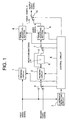
- Fig. 1 shows an video signal processing apparatus according to the present invention.
- the video signal processing apparatus is provided within a television receiver having a display screen in an aspect ratio of 16 : 9, e.g. a PDP (plasma display panel) television receiver.
- the video signal processing apparatus is arranged to input therein two video signals.
- the first video signal is an SDTV (standard definition television) video signal having an aspect ratio of 4 : 3, e.g. an NTSC-schemed video signal.
- the second video signal although not limited, is an SDTV video signal having an aspect ratio of 4 : 3 or an HDTV (high definition television) video signal having an aspect ratio of 6 : 9.
- the video signal processing apparatus has an output connected to an image input system of the television receiver.
- the video signal processing apparatus comprises resizing circuits 1, 2, a luminance detecting circuit 3, selector switches 4, 7, 10, a control circuit 5, a monochromatizing LPF 6 and timing adjusting sections 8, 9.
- the resizing circuit 1 is supplied with the first video signal.
- the resizing circuit 1 converts the first video signal so that the on-screen display based on the first video signal can be vertically enlarged.
- the first video signal is line-interpolated and converted into an video signal matched for the number of scanning lines of the television receiver. Meanwhile, vertical black stripes are caused to form blanks at both the left and right of the screen. Because the first video signal is in the number of scanning lines of 525, the first video signal is converted into an HDTV video signal having the number of scanning lines of 1080 or 720.
- the resizing circuit 1 has an output connected with a luminance detecting circuit 3, a selector switch 4 and a timing adjusting section 8.
- the luminance detecting circuit 3 detects a luminance level of the output video signal of the resizing circuit 1.
- the luminance detection signal representative of the detection result is supplied to a control circuit 5.
- the selector switch 4 is supplied with both an output video signal of the resizing circuit 1 and a second video signal.
- the selector switch 4 selectively supplies one of the first and second video signals to the resizing circuit 2, in response to an instruction of the control circuit 5.
- the resizing circuit 2 converts the video signal so that on-screen display based on the video signal supplied through the selector switch 4 can be enlarged to the left and right.
- the resizing circuit 2 decompresses the video signal equally in time to the left and right of the screen.
- the resizing circuit 2 is placed in a through state when an HDTV video signal is supplied as the second video signal.
- the resizing circuit 2 has an output connected with a monochromatizing LPF 6.
- the monochromatizing LPF 6 allows only the lower component of the video signal supplied from the sizing circuit 2 to pass, thereby monochromatizing the video signal.
- the monochromatizing LPF 7 is provided with a selector switch 7.
- the selector switch 7 has one input connected with an output of the monochromatizing LPF 6 and the other input connected with an output of the resizing circuit 2.
- the selector switch 7 selectively supplies one of an output video signal of the resizing circuit 2 and an output video signal of the monochromatizing LPF 6 to the timing adjusting section 9, in response to an instruction of the control circuit 5.
- the timing adjusting sections 8, 9 adjust the output timing of a supplied video signal, in response to an instruction of the control circuit 5.
- the timing adjusting sections 8, 9 have an output connected with a selector switch 10 for combining the video signal.
- the output of the selector switch 10 is provided as an output of the video signal processing apparatus.
- the selector switch 10 selectively outputs any one of output video signals of the timing adjusting sections 8, 9, in response to an instruction of the control circuit 5.
- the control circuit 5 issues various instructions in accordance with the luminance detection signal supplied from the luminance detecting circuit 3. Meanwhile, although not shown, the horizontal synchronizing signal in an output video signal of the resizing circuit 1 is supplied to the control circuit 5.
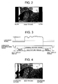
- the on-screen picture represented by an video signal output from the resizing circuit 1 is caused with black blanks at left and right of the screen for example, as shown in Fig. 2.
- the picture itself except for blanks has an aspect ratio of 4 : 3.
- the video signal having blanks output from the resizing circuit 1 has a luminance signal and a horizontal synchronizing signal, as shown in Fig. 3.
- the output video signal of the resizing circuit 1 is supplied to the timing adjusting section 8 and also to the luminance detecting circuit 3.
- the luminance detecting circuit 3 takes a luminance period when the output video signal of the resizing circuit 1 is greater than a threshold, to generate a luminance detection signal as shown in Fig. 3.
- the luminance detection signal is supplied to the control circuit 5.
- the control circuit 5 takes, as a first blank period, a period of after generating a horizontal synchronizing signal and before generating a luminance detection signal. Furthermore, it determines as a second blank period a period of after extinction of the luminance detection signal and before an occurrence of a horizontal synchronizing signal. Incidentally, actually each blank period has a non-display period relative to the horizontal synchronizing signal, as shown in Fig. 3.
- the resizing circuit 2 In the state that the output video signal of the resizing circuit 1 is supplied to the resizing circuit 2 through the selector switch 4, the resizing circuit 2 is instructed a luminance period of within an output video signal of the resizing circuit 1, i.e. real video period, by the control circuit 5. Accordingly, it converts the video signal in response to the instruction such that the real video part is enlarged to the left and right.
- the video signal converted by the resizing circuit 2 has an aspect ratio of 16 : 9, being on the real image free of a blank.
- the converted video signal is supplied to the monochrotizing LPF 6 where it turns into a monochromatic video signal removed of color component.
- the selector switch 7 supplies an output video signal of the resizing circuit 2 and a monochromatic video signal thereof.
- the selector switch 7 selects any one of the output video signal of the resizing circuit 2 and an output video signal of the monochrotizing LPF 6, in response to an instruction of the control circuit 5, and supplies the selected signal to the timing adjusting section 9.
- the control circuit 5 generates a timing adjusting command for the timing adjusting sections 8, 9 to take synchronization on the video signal with each other. Due to timing adjustment by the timing adjusting sections 8, 9, synchronous agreement is taken mutually between an video signal A having blanks and a video signal B inserted with a real image in each of the blanks that are to be supplied to the selector switch 10.
- the selector switch 10 in each blank period of the video signal A having blanks, selects and outputs the video signal B in response to an instruction from the control circuit 5. Meanwhile, out of the blank period, the video signal A is selected and output by the selector switch 10. Accordingly, as shown in Fig. 4, the video signal outputted from the selector switch 10 represents a picture based on the video signal B in a region corresponding to each of the left and right blanks on the screen of the display having an aspect ratio of 16 : 9. In the other region, represented is the main image based on the video signal A having an aspect ratio of 4 : 3.
- a monochromatic picture related to the main picture is arranged in the region corresponding to each of the left and right blanks on the screen.
- the arrangement may be by a defocused or enlarged picture related to the main picture represented by the output video signal of the resizing circuit 2.
- the present invention is applicable to the case that blanks are present at the upper and lower on the screen, the case that they exist at the upper and lower and left and right on the screen, or the case that a single blank is present at one side on the screen.
- the above embodiment explained the case that the video signal with a picture size having an aspect ratio of 4 : 3 is converted into an video signal with a picture size having an aspect ratio of 16 : 9 to thereby making an image on each of the blanks.
- image processing is similarly possible for the case to directly input a video signal with a picture size having an aspect ratio of 16 : 9 representing a main picture in a picture size having an aspect ratio of 4 : 3 and blanks in the other display region than the main picture.
Landscapes
- Engineering & Computer Science (AREA)
- Computer Graphics (AREA)
- Multimedia (AREA)
- Signal Processing (AREA)
- Television Systems (AREA)
- Transforming Electric Information Into Light Information (AREA)
- Studio Circuits (AREA)
Abstract
Description
- The present invention relates to a video signal processing apparatus for converting an input video signal into a video signal having a picture size with an aspect ratio different from an aspect ratio of the video image thereof.
- In the current television broadcast, implemented are SDTV (standard definition television) broadcast having an aspect ratio of 4 : 3 and HDTV (high definition television) broadcast having an aspect ratio of 16 : 9. In the HDTV broadcast, when carrying out a broadcast with an SDTV picture signal having the aspect ratio of 4 : 3, the broadcast station converts the signal into a picture signal having an aspect ratio of 16 : 9 and then sends it into the air. Consequently, when the converted picture signal is received by an HDTV television receiver, usually a picture having the aspect ratio of 4 : 3 is displayed in the center of the screen while black blanks are displayed on the left and right side thereof.
- In this manner, there is a problem that, when displaying a main picture having an aspect ratio different from that of the television receiver screen together with blanks, the picture being displayed is perceived unnatural and felt unsuitable by the viewer due to the presence of blanks.
- It is an object of the present invention to provide a video signal processing apparatus capable of converting a video signal having a main picture and blanks into a video signal lessened in unsuitableness of picture.
- A video signal processing apparatus of the present invention is a video signal processing apparatus for picture-processing a video signal which is representative of a picture having a main picture having a picture size of a first aspect ratio and at least one blank lying in a region of other than the main picture and which has a picture size of a second aspect ratio different from the first aspect ratio, the video signal processing apparatus comprising: means for detecting a blank of a picture represented by the video signal; means for generating an video signal representative of a processed picture based on an video signal corresponding to a part of the main picture, in accordance with a detection of the blank by the blank detecting means; and means for adding the video signal representative of the processed picture to an video signal representative of the main picture.
-
- Fig. 1 is a block diagram showing a video signal processing apparatus according to the present invention;
- Fig. 2 shows a picture with an aspect ratio of 16 : 9 having blanks in the left and right of the screen;
- Fig. 3 is a waveform diagram showing the operation of the apparatus of Fig. 1; and
- Fig. 4 shows a picture with an aspect ratio of 16 : 9 having processed pictures in the left and right of the screen.
- Now an embodiment of the present invention will be explained in detail while referring to the drawings.
- Fig. 1 shows an video signal processing apparatus according to the present invention. The video signal processing apparatus is provided within a television receiver having a display screen in an aspect ratio of 16 : 9, e.g. a PDP (plasma display panel) television receiver. The video signal processing apparatus is arranged to input therein two video signals. The first video signal is an SDTV (standard definition television) video signal having an aspect ratio of 4 : 3, e.g. an NTSC-schemed video signal. The second video signal, although not limited, is an SDTV video signal having an aspect ratio of 4 : 3 or an HDTV (high definition television) video signal having an aspect ratio of 6 : 9. The video signal processing apparatus has an output connected to an image input system of the television receiver.
- The video signal processing apparatus comprises resizing
circuits 1, 2, aluminance detecting circuit 3,selector switches control circuit 5, a monochromatizing LPF 6 and timing adjustingsections circuit 1 is supplied with the first video signal. The resizingcircuit 1 converts the first video signal so that the on-screen display based on the first video signal can be vertically enlarged. For example, the first video signal is line-interpolated and converted into an video signal matched for the number of scanning lines of the television receiver. Meanwhile, vertical black stripes are caused to form blanks at both the left and right of the screen. Because the first video signal is in the number of scanning lines of 525, the first video signal is converted into an HDTV video signal having the number of scanning lines of 1080 or 720. The resizingcircuit 1 has an output connected with aluminance detecting circuit 3, aselector switch 4 and atiming adjusting section 8. - The
luminance detecting circuit 3 detects a luminance level of the output video signal of the resizingcircuit 1. The luminance detection signal representative of the detection result is supplied to acontrol circuit 5. - The
selector switch 4 is supplied with both an output video signal of the resizingcircuit 1 and a second video signal. The selector switch 4 selectively supplies one of the first and second video signals to the resizing circuit 2, in response to an instruction of thecontrol circuit 5. - The resizing circuit 2 converts the video signal so that on-screen display based on the video signal supplied through the
selector switch 4 can be enlarged to the left and right. The resizing circuit 2 decompresses the video signal equally in time to the left and right of the screen. The resizing circuit 2 is placed in a through state when an HDTV video signal is supplied as the second video signal. - The resizing circuit 2 has an output connected with a monochromatizing LPF 6. The monochromatizing LPF 6 allows only the lower component of the video signal supplied from the sizing circuit 2 to pass, thereby monochromatizing the video signal.
- The
monochromatizing LPF 7 is provided with aselector switch 7. Theselector switch 7 has one input connected with an output of the monochromatizing LPF 6 and the other input connected with an output of the resizing circuit 2. The selector switch 7 selectively supplies one of an output video signal of the resizing circuit 2 and an output video signal of the monochromatizing LPF 6 to thetiming adjusting section 9, in response to an instruction of thecontrol circuit 5. - The
timing adjusting sections control circuit 5. Thetiming adjusting sections selector switch 10 for combining the video signal. The output of theselector switch 10 is provided as an output of the video signal processing apparatus. The selector switch 10 selectively outputs any one of output video signals of thetiming adjusting sections control circuit 5. - The
control circuit 5 issues various instructions in accordance with the luminance detection signal supplied from theluminance detecting circuit 3. Meanwhile, although not shown, the horizontal synchronizing signal in an output video signal of the resizingcircuit 1 is supplied to thecontrol circuit 5. - In the video signal processing apparatus thus arranged, the on-screen picture represented by an video signal output from the resizing
circuit 1 is caused with black blanks at left and right of the screen for example, as shown in Fig. 2. The picture itself except for blanks has an aspect ratio of 4 : 3. - The video signal having blanks output from the resizing
circuit 1 has a luminance signal and a horizontal synchronizing signal, as shown in Fig. 3. The output video signal of the resizingcircuit 1 is supplied to thetiming adjusting section 8 and also to theluminance detecting circuit 3. - The
luminance detecting circuit 3 takes a luminance period when the output video signal of the resizingcircuit 1 is greater than a threshold, to generate a luminance detection signal as shown in Fig. 3. The luminance detection signal is supplied to thecontrol circuit 5. Thecontrol circuit 5 takes, as a first blank period, a period of after generating a horizontal synchronizing signal and before generating a luminance detection signal. Furthermore, it determines as a second blank period a period of after extinction of the luminance detection signal and before an occurrence of a horizontal synchronizing signal. Incidentally, actually each blank period has a non-display period relative to the horizontal synchronizing signal, as shown in Fig. 3. - In the state that the output video signal of the resizing
circuit 1 is supplied to the resizing circuit 2 through theselector switch 4, the resizing circuit 2 is instructed a luminance period of within an output video signal of the resizingcircuit 1, i.e. real video period, by thecontrol circuit 5. Accordingly, it converts the video signal in response to the instruction such that the real video part is enlarged to the left and right. The video signal converted by the resizing circuit 2 has an aspect ratio of 16 : 9, being on the real image free of a blank. The converted video signal is supplied to the monochrotizing LPF 6 where it turns into a monochromatic video signal removed of color component. - To the
selector switch 7, supplied are an output video signal of the resizing circuit 2 and a monochromatic video signal thereof. Theselector switch 7 selects any one of the output video signal of the resizing circuit 2 and an output video signal of the monochrotizing LPF 6, in response to an instruction of thecontrol circuit 5, and supplies the selected signal to thetiming adjusting section 9. Thecontrol circuit 5 generates a timing adjusting command for thetiming adjusting sections timing adjusting sections selector switch 10. - The
selector switch 10, in each blank period of the video signal A having blanks, selects and outputs the video signal B in response to an instruction from thecontrol circuit 5. Meanwhile, out of the blank period, the video signal A is selected and output by theselector switch 10. Accordingly, as shown in Fig. 4, the video signal outputted from theselector switch 10 represents a picture based on the video signal B in a region corresponding to each of the left and right blanks on the screen of the display having an aspect ratio of 16 : 9. In the other region, represented is the main image based on the video signal A having an aspect ratio of 4 : 3. - In the above embodiment, a monochromatic picture related to the main picture is arranged in the region corresponding to each of the left and right blanks on the screen. However, the arrangement may be by a defocused or enlarged picture related to the main picture represented by the output video signal of the resizing circuit 2.
- The above embodiment explained the case that the blanks of the video signal are present at left and right on the screen. However, without limited to that, the present invention is applicable to the case that blanks are present at the upper and lower on the screen, the case that they exist at the upper and lower and left and right on the screen, or the case that a single blank is present at one side on the screen.
- Further, the above embodiment explained the case that the video signal with a picture size having an aspect ratio of 4 : 3 is converted into an video signal with a picture size having an aspect ratio of 16 : 9 to thereby making an image on each of the blanks. However, image processing is similarly possible for the case to directly input a video signal with a picture size having an aspect ratio of 16 : 9 representing a main picture in a picture size having an aspect ratio of 4 : 3 and blanks in the other display region than the main picture.
- As described above, according to the present invention, since processed images based on the main picture are displayed in regions corresponding to blanks of a display picture, the viewer is allowed to view it as a picture integrated with the display picture. There is less unsuitableness as compared to the case with blanked display. Furthermore, image sticking prevention of the display-panel can be expected as compared to the case of blanked display.
Claims (4)
- A video signal processing apparatus for picture-processing a video signal which is representative of a picture having a main picture having a picture size of a first aspect ratio and at least one blank lying in a region of other than the main picture and which has a picture size of a second aspect ratio different from the first aspect ratio, the video signal processing apparatus comprising:means for detecting a blank of a picture represented by the video signal;means for generating an video signal representative of a processed picture based on an video signal corresponding to a part of the main picture, in accordance with a detection of the blank by the blank detecting means; andmeans for adding the video signal representative of the processed picture to an video signal representative of the main picture.
- An video signal processing apparatus according to claim 1, wherein the processed picture is a monochromatic picture.
- An video signal processing apparatus according to claim 1, wherein the processed picture is an enlarged picture.
- An video signal processing apparatus according to claim 1, wherein the processed picture is an unfocused picture.
Applications Claiming Priority (2)
| Application Number | Priority Date | Filing Date | Title |
|---|---|---|---|
| JP2003184241 | 2003-06-27 | ||
| JP2003184241A JP2005020512A (en) | 2003-06-27 | 2003-06-27 | Video signal processing apparatus |
Publications (2)
| Publication Number | Publication Date |
|---|---|
| EP1492335A1 true EP1492335A1 (en) | 2004-12-29 |
| EP1492335B1 EP1492335B1 (en) | 2006-12-13 |
Family
ID=33411130
Family Applications (1)
| Application Number | Title | Priority Date | Filing Date |
|---|---|---|---|
| EP04013885A Expired - Lifetime EP1492335B1 (en) | 2003-06-27 | 2004-06-14 | Video signal processing apparatus |
Country Status (4)
| Country | Link |
|---|---|
| US (1) | US20040263683A1 (en) |
| EP (1) | EP1492335B1 (en) |
| JP (1) | JP2005020512A (en) |
| DE (1) | DE602004003630T2 (en) |
Cited By (2)
| Publication number | Priority date | Publication date | Assignee | Title |
|---|---|---|---|---|
| WO2007113754A1 (en) * | 2006-03-31 | 2007-10-11 | Koninklijke Philips Electronics N.V. | Adaptive rendering of video content based on additional frames of content |
| EP3330953A4 (en) * | 2015-07-31 | 2018-07-11 | Samsung Electronics Co., Ltd. | Display method and apparatus for electronic device |
Families Citing this family (5)
| Publication number | Priority date | Publication date | Assignee | Title |
|---|---|---|---|---|
| JP5263565B2 (en) * | 2006-10-12 | 2013-08-14 | ソニー株式会社 | Image processing apparatus, image processing method, and program |
| JP5024028B2 (en) * | 2007-12-21 | 2012-09-12 | フリュー株式会社 | Image conversion apparatus, image providing system, photographing / editing apparatus, image conversion method, image conversion program, and recording medium recording the program |
| JP5218687B2 (en) * | 2012-04-26 | 2013-06-26 | フリュー株式会社 | Image conversion apparatus, image providing system, photographing / editing apparatus, image conversion method, image conversion program, and recording medium recording the program |
| CN107395971B (en) * | 2017-07-31 | 2020-06-12 | 上海新眼光医疗器械股份有限公司 | Image acquisition method, image acquisition equipment and computer-readable storage medium |
| JP6591000B1 (en) * | 2018-06-20 | 2019-10-16 | ヤフー株式会社 | Image processing apparatus, image processing method, and image processing program |
Citations (2)
| Publication number | Priority date | Publication date | Assignee | Title |
|---|---|---|---|---|
| US5956092A (en) * | 1993-10-20 | 1999-09-21 | Victor Company Of Japan, Ltd. | Television receiver with adjustable frame size |
| US20030035482A1 (en) * | 2001-08-20 | 2003-02-20 | Klompenhouwer Michiel Adriaanszoon | Image size extension |
Family Cites Families (12)
| Publication number | Priority date | Publication date | Assignee | Title |
|---|---|---|---|---|
| US4730215A (en) * | 1986-05-30 | 1988-03-08 | Rca Corporation | Compatible wide screen television system with variable image compression/expansion |
| US5126844A (en) * | 1987-06-02 | 1992-06-30 | North American Philips Corporation | Decomposition and recombination of a wide-aspect ratio image |
| JPH0372796A (en) * | 1989-04-28 | 1991-03-27 | Matsushita Electric Ind Co Ltd | television signal processing equipment |
| EP0439605B1 (en) * | 1989-08-23 | 1997-03-26 | Thomson Consumer Electronics, Inc. | Convergence control system for multiple vertical formats |
| JP2533393B2 (en) * | 1990-02-16 | 1996-09-11 | シャープ株式会社 | NTSC-HD converter |
| US5032917A (en) * | 1990-03-12 | 1991-07-16 | Rca Licensing Corporation | Video signal blending apparatus |
| JPH03263987A (en) * | 1990-03-13 | 1991-11-25 | Toshiba Corp | Transmitter and receiver for additional signal multiplex television signal |
| JPH06189231A (en) * | 1992-12-16 | 1994-07-08 | Toshiba Corp | Liquid crystal display |
| JP3231142B2 (en) * | 1993-06-18 | 2001-11-19 | 株式会社日立製作所 | Video compression / expansion circuit and device |
| KR970008379B1 (en) * | 1993-09-08 | 1997-05-23 | Samsung Electronics Co Ltd | Method and apparatus for decreasing side blank of wide screen |
| US5847768A (en) * | 1996-04-26 | 1998-12-08 | Lg Electronics Inc. | Apparatus for converting screen aspect ratio |
| TW408242B (en) * | 1997-03-27 | 2000-10-11 | Toshiba Corp | Flat-panel display device and display method |
-
2003
- 2003-06-27 JP JP2003184241A patent/JP2005020512A/en active Pending
-
2004
- 2004-06-14 DE DE602004003630T patent/DE602004003630T2/en not_active Expired - Fee Related
- 2004-06-14 EP EP04013885A patent/EP1492335B1/en not_active Expired - Lifetime
- 2004-06-25 US US10/875,284 patent/US20040263683A1/en not_active Abandoned
Patent Citations (2)
| Publication number | Priority date | Publication date | Assignee | Title |
|---|---|---|---|---|
| US5956092A (en) * | 1993-10-20 | 1999-09-21 | Victor Company Of Japan, Ltd. | Television receiver with adjustable frame size |
| US20030035482A1 (en) * | 2001-08-20 | 2003-02-20 | Klompenhouwer Michiel Adriaanszoon | Image size extension |
Cited By (3)
| Publication number | Priority date | Publication date | Assignee | Title |
|---|---|---|---|---|
| WO2007113754A1 (en) * | 2006-03-31 | 2007-10-11 | Koninklijke Philips Electronics N.V. | Adaptive rendering of video content based on additional frames of content |
| RU2454023C2 (en) * | 2006-03-31 | 2012-06-20 | Конинклейке Филипс Электроникс Н.В. | Adaptive play of television content based on additional content frames |
| EP3330953A4 (en) * | 2015-07-31 | 2018-07-11 | Samsung Electronics Co., Ltd. | Display method and apparatus for electronic device |
Also Published As
| Publication number | Publication date |
|---|---|
| DE602004003630D1 (en) | 2007-01-25 |
| EP1492335B1 (en) | 2006-12-13 |
| JP2005020512A (en) | 2005-01-20 |
| DE602004003630T2 (en) | 2007-09-20 |
| US20040263683A1 (en) | 2004-12-30 |
Similar Documents
| Publication | Publication Date | Title |
|---|---|---|
| US7982810B2 (en) | Panel-type image display device and liquid crystal television | |
| EP1404130A1 (en) | Method and apparatus for processing a video signal mixed with an additional image signal | |
| US6798458B1 (en) | Image signal conversion equipment | |
| US20050117813A1 (en) | Image reproducing apparatus and image reproducing method | |
| KR20030046713A (en) | Image display device and operating method for thereof | |
| KR100699091B1 (en) | Display device and control method | |
| US5418576A (en) | Television receiver with perceived contrast reduction in a predetermined area of a picture where text is superimposed | |
| KR20060122589A (en) | Display device and control method | |
| EP1492335B1 (en) | Video signal processing apparatus | |
| US5539474A (en) | Method and apparatus for shifting a display position of a small-sized picture on a display screen of a television receiver | |
| JP2004194311A (en) | Video playback device and video playback method | |
| KR20060009597A (en) | Video signal synthesizing method, video signal synthesizing apparatus, display system, display apparatus and control method of display apparatus | |
| JPH077685A (en) | Television receiver | |
| KR20070014586A (en) | PiP display control method | |
| JP2001103518A (en) | Video signal creation device and video signal creation method | |
| KR20080011026A (en) | Image processing apparatus and image processing method | |
| JP2998156B2 (en) | Television receiver | |
| JPH04322577A (en) | Television receiver | |
| KR20020078338A (en) | Apparatus and method for synchronizing digital televison screen | |
| KR200162110Y1 (en) | On-screen cursor moving device according to serial communication protocol | |
| KR100767861B1 (en) | Input signal processing device and method in image display device | |
| JP3019032U (en) | TV with built-in teletext broadcasting decoder | |
| JP2006140627A (en) | Video signal processing device, television receiver | |
| KR20010063359A (en) | Display apparatus | |
| JPH06125482A (en) | Correction range designation circuit for black level correction circuit |
Legal Events
| Date | Code | Title | Description |
|---|---|---|---|
| PUAI | Public reference made under article 153(3) epc to a published international application that has entered the european phase |
Free format text: ORIGINAL CODE: 0009012 |
|
| AK | Designated contracting states |
Kind code of ref document: A1 Designated state(s): AT BE BG CH CY CZ DE DK EE ES FI FR GB GR HU IE IT LI LU MC NL PL PT RO SE SI SK TR |
|
| AX | Request for extension of the european patent |
Extension state: AL HR LT LV MK |
|
| 17P | Request for examination filed |
Effective date: 20050121 |
|
| 17Q | First examination report despatched |
Effective date: 20050218 |
|
| AKX | Designation fees paid |
Designated state(s): DE FR GB |
|
| GRAP | Despatch of communication of intention to grant a patent |
Free format text: ORIGINAL CODE: EPIDOSNIGR1 |
|
| GRAS | Grant fee paid |
Free format text: ORIGINAL CODE: EPIDOSNIGR3 |
|
| GRAA | (expected) grant |
Free format text: ORIGINAL CODE: 0009210 |
|
| AK | Designated contracting states |
Kind code of ref document: B1 Designated state(s): DE FR GB |
|
| REG | Reference to a national code |
Ref country code: GB Ref legal event code: FG4D |
|
| REF | Corresponds to: |
Ref document number: 602004003630 Country of ref document: DE Date of ref document: 20070125 Kind code of ref document: P |
|
| PGFP | Annual fee paid to national office [announced via postgrant information from national office to epo] |
Ref country code: DE Payment date: 20070706 Year of fee payment: 4 |
|
| ET | Fr: translation filed | ||
| PLBE | No opposition filed within time limit |
Free format text: ORIGINAL CODE: 0009261 |
|
| STAA | Information on the status of an ep patent application or granted ep patent |
Free format text: STATUS: NO OPPOSITION FILED WITHIN TIME LIMIT |
|
| 26N | No opposition filed |
Effective date: 20070914 |
|
| PGFP | Annual fee paid to national office [announced via postgrant information from national office to epo] |
Ref country code: FR Payment date: 20070619 Year of fee payment: 4 |
|
| GBPC | Gb: european patent ceased through non-payment of renewal fee |
Effective date: 20080614 |
|
| REG | Reference to a national code |
Ref country code: FR Ref legal event code: ST Effective date: 20090228 |
|
| PG25 | Lapsed in a contracting state [announced via postgrant information from national office to epo] |
Ref country code: DE Free format text: LAPSE BECAUSE OF NON-PAYMENT OF DUE FEES Effective date: 20090101 |
|
| PG25 | Lapsed in a contracting state [announced via postgrant information from national office to epo] |
Ref country code: GB Free format text: LAPSE BECAUSE OF NON-PAYMENT OF DUE FEES Effective date: 20080614 |
|
| PG25 | Lapsed in a contracting state [announced via postgrant information from national office to epo] |
Ref country code: FR Free format text: LAPSE BECAUSE OF NON-PAYMENT OF DUE FEES Effective date: 20080630 |