EP1492152A2 - Electron microscope - Google Patents
Electron microscope Download PDFInfo
- Publication number
- EP1492152A2 EP1492152A2 EP20040253856 EP04253856A EP1492152A2 EP 1492152 A2 EP1492152 A2 EP 1492152A2 EP 20040253856 EP20040253856 EP 20040253856 EP 04253856 A EP04253856 A EP 04253856A EP 1492152 A2 EP1492152 A2 EP 1492152A2
- Authority
- EP
- European Patent Office
- Prior art keywords
- specimen
- image
- electron microscope
- signal processing
- processing circuit
- Prior art date
- Legal status (The legal status is an assumption and is not a legal conclusion. Google has not performed a legal analysis and makes no representation as to the accuracy of the status listed.)
- Granted
Links
- 238000000034 method Methods 0.000 claims abstract description 27
- 238000003325 tomography Methods 0.000 claims abstract description 20
- 238000003917 TEM image Methods 0.000 claims description 31
- 238000010894 electron beam technology Methods 0.000 claims description 7
- 229910052704 radon Inorganic materials 0.000 claims description 6
- SYUHGPGVQRZVTB-UHFFFAOYSA-N radon atom Chemical compound [Rn] SYUHGPGVQRZVTB-UHFFFAOYSA-N 0.000 claims description 6
- 239000000284 extract Substances 0.000 claims description 5
- 230000000694 effects Effects 0.000 claims description 2
- 230000005540 biological transmission Effects 0.000 abstract description 51
- 238000001228 spectrum Methods 0.000 description 9
- 238000002247 constant time method Methods 0.000 description 7
- 238000001493 electron microscopy Methods 0.000 description 5
- 238000005520 cutting process Methods 0.000 description 3
- 238000009826 distribution Methods 0.000 description 2
- 238000000605 extraction Methods 0.000 description 2
- 238000010521 absorption reaction Methods 0.000 description 1
- 238000004458 analytical method Methods 0.000 description 1
- 230000001419 dependent effect Effects 0.000 description 1
- 238000005286 illumination Methods 0.000 description 1
- 238000004519 manufacturing process Methods 0.000 description 1
- 238000001000 micrograph Methods 0.000 description 1
- 238000012986 modification Methods 0.000 description 1
- 230000004048 modification Effects 0.000 description 1
- 238000012876 topography Methods 0.000 description 1
- 230000001131 transforming effect Effects 0.000 description 1
- 238000004627 transmission electron microscopy Methods 0.000 description 1
Images


Classifications
-
- H—ELECTRICITY
- H01—ELECTRIC ELEMENTS
- H01J—ELECTRIC DISCHARGE TUBES OR DISCHARGE LAMPS
- H01J37/00—Discharge tubes with provision for introducing objects or material to be exposed to the discharge, e.g. for the purpose of examination or processing thereof
- H01J37/02—Details
- H01J37/22—Optical, image processing or photographic arrangements associated with the tube
-
- H—ELECTRICITY
- H01—ELECTRIC ELEMENTS
- H01J—ELECTRIC DISCHARGE TUBES OR DISCHARGE LAMPS
- H01J37/00—Discharge tubes with provision for introducing objects or material to be exposed to the discharge, e.g. for the purpose of examination or processing thereof
- H01J37/26—Electron or ion microscopes; Electron or ion diffraction tubes
-
- H—ELECTRICITY
- H01—ELECTRIC ELEMENTS
- H01J—ELECTRIC DISCHARGE TUBES OR DISCHARGE LAMPS
- H01J2237/00—Discharge tubes exposing object to beam, e.g. for analysis treatment, etching, imaging
- H01J2237/22—Treatment of data
- H01J2237/226—Image reconstruction
-
- H—ELECTRICITY
- H01—ELECTRIC ELEMENTS
- H01J—ELECTRIC DISCHARGE TUBES OR DISCHARGE LAMPS
- H01J2237/00—Discharge tubes exposing object to beam, e.g. for analysis treatment, etching, imaging
- H01J2237/26—Electron or ion microscopes
- H01J2237/2611—Stereoscopic measurements and/or imaging
Definitions
- the present invention relates to a transmission electron microscope (TEM) capable of analyzing the three-dimensional structure of a specimen without sectioning it.
- TEM transmission electron microscope
- CT computerized tomography
- the present invention has been proposed. It would be desirable to provide an electron microscope capable of analyzing the three-dimensional structure of a specimen without sectioning it by making use of computerized tomography. It would also be desirable to provide an electron microscope permitting application of computerized tomography to general cases by solving the problems intrinsically occurring when computerized tomography is applied to the electron microscope, i.e., limitations on the tilt angle of the specimen stage and problems associated with identification of the axis of rotation and rotation and shift of the image.
- an electron microscope which addresses the above-described problems and acts to direct an electron beam at a specimen supported tiltably and to gain TEM images based on electrons transmitted through the specimen.
- the microscope is fitted with a signal processing circuit for implementing computerized tomography based on data about the gained TEM images of the specimen.
- the signal processing circuit selects and extracts the same field of view from a series of TEM images obtained by tiling the specimen by plural angles by two-dimensional correlation processing between each TEM image and a reference image. Thus, positional deviation of the specimen is corrected.
- a method of analyzing a three-dimensional structure using an electron microscope (1) fitted with a signal processing circuit (2) , the method comprising the steps of : directing an electron beam at a specimen (S) supported tiltably; gaining TEM images based on electrons transmitted through the specimen; implementing computerized tomography according to data about the gained TEM images of the specimen, wherein said signal processing circuit performs two-dimensional correlation processing between each of a series of TEM images obtained from the specimen tilted by plural angles and a reference image to thereby select and extract an identical field of view, whereby correcting positional deviation of the specimen.
- the method also comprises steps discernible from claims 2 to 6.
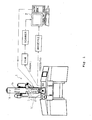
- Fig. 1 is a perspective view of an electron microscope according to one embodiment of the invention, showing its whole appearance.
- the electron microscope is a transmission electron microscope (TEM) and has an electron gun 1a emitting an electron beam, an illumination lens system 1b (condenser lens system) for directing the beam at a specimen S, a focusing lens system 1c for focusing a TEM image based on electrons transmitted through the specimen, and a TEM image detector 1d for detecting the focused TEM image.
- TEM transmission electron microscope
- the electron microscope 1 performs a three-dimensional reconstruction of the TEM image by CT (computerized tomography) .
- the microscope 1 is fitted with a signal processing circuit (computer) 2 for implementing a CT procedure based on the TEM image of the specimen gained by the TEM image detector 1d.
- the specimen is supported on a specimen stage 3 capable of being rotated and tilted.
- the stage 3 can be automatically moved under control of the signal processing circuit 2.
- the signal processing circuit 2 accepts necessary information while moving the specimen stage 3 in various kinds of processing (described later) and performs these kinds of processing automatically.
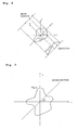
- Fig. 2 is a plan view illustrating the principle of computerized tomography (CT) applied to the electron microscope according to the present embodiment of the invention.
- CT computerized tomography
- the integral transform that makes f (x,y) correspond to p (r, ⁇ ) as mentioned previously is known as the Radon transform.
- the cross-sectional reconstruction from the projections is carried out by an inverse process of this transform, i.e., inverse Radon transform (back projection). This is hereinafter referred to as the back projection.
- Fig. 3 is a plan view showing the resulting state.
- a two-dimensional (2D) Fourier spectrum of cross sections of the specimen can be found by Fourier-transforming projections from all directions through the specimen and arraying the resulting spectra in a Fourier space.
- Cross-sectional images of the specimen can be obtained by inverse-Fourier transforming the 2D Fourier spectrum.
- a two-dimensional image (cross-sectional image) can be reconstructed from one-dimensional projections. Since a TEM image is a 2D projection, a three-dimensional image can be reconstructed simply by rotating the specimen along the axis of rotation.
- Fig. 4 is a perspective view illustrating the process for reconstructing a three-dimensional image. That is, a data array in a direction perpendicular to the axis of rotation is regarded as a 1D projection. A cross-sectional image is reconstructed from projections from various angles. A 3D image can be obtained by stacking 2D images obtained in this way along the axis of rotation.
- a series of transmission images is obtained by tilting the specimen in incremental angular steps.
- the same field of view is selected and extracted from the series of transmission images by two-dimensional correlation processing. In this way, the problem of positional deviation of the specimen is solved.
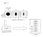
- Fig. 5 is a front elevation illustrating the process for selecting and extracting the same field of view from a series of transmission images by two-dimensional correlation processing, the series of transmission images being obtained by tilting a specimen in incremental angular steps.
- two-dimensional correlation processing is performed between each obtained transmission image and a reference image.
- Parts of the transmission images which have the same field of view as the reference image are extracted from the transmission images at different angles.
- Computerized tomography is done using the extracted images.
- the reference image is obtained by extracting an image of a part of field of view from the transmission image obtained when the specimen stage is at some tilt angle (e.g., 0°).
- the accuracy at which transmission images are extracted by two-dimensional correlation processing can be improved by removing the trend in the transmission images (i.e., by removing first-order component or bias component).
- the reliability that the identified maximum value is a true maximum value is low. In this case, the reliability of the alignment (extraction of image) is deteriorated severely.
- [Ave] is the average value of the correlation over the whole transmission image.
- cofEq. (9) or (10) described later is used, for example.
- c (i, j) ⁇ f ( x , y ) g ( x - i , y - j ) dx dy
- the degree of similarity is calculated in succession while translating the reference image within the image of interest. Because of the characteristics of the electronmicroscope, rotational movement is produced between the reference image and the image of interest.
- Eq. (9) is modified into Eq. (10) by adding a rotation through ⁇ within the xy plane with respect to a point within the image.
- This point within the image does not need to be the center of the image as long as it is a fixed point.
- c ( i , j , ⁇ ) ⁇ f ( x , y ) g ( x - i , y -j, ⁇ ) dx dy d ⁇
- an image of a field of view that will become a reference image is extracted from a transmission image when the specimen stage is at some tilt angle (e.g., 0°). Then, 2D correlation processing is performed between the reference image and a transmission image derived when the specimen stage is at a different tilt angle. A field of view producing a maximum amount of correlation is extracted. The extracted field of view is rotated or tilted in the direction of ⁇ within the transmission image. Each such a field of view is multiplied with the reference image, and the total sum is taken. An image closest to the reference image can be obtained by adopting the maximum value of those values. That is, the rotation (tilt) in the direction of ⁇ within the transmission image is corrected. This processing is carried out repetitively. In consequence, images of the same field of view can be accurately extracted regarding transmission images at all tilt angles.
- some tilt angle e.g., 0°
- 2D correlation processing is performed between the reference image and a transmission image derived when the specimen stage is at a different tilt angle.
- an image extracted from the transmission image obtained when the specimen stage is at some tilt angle is not used for transmission images at all tilt angles . Rather, an image of the same field of view extracted from a transmission image at a different tilt angle using some reference image is used as a new reference image for 2D correlation processing between the reference image and a transmission image at a further tilt angle.
- Fig. 6 is a front elevation showing one example of process of performing 2D correlation processing using successively new reference images.
- an image of the same field of view is extracted from a transmission image obtained when the tilt angle of the stage is 30°.
- an image of the same field of view is extracted from a transmission image obtained when the tilt angle of the stage is 60° . Consequently, it is possible to avoid the problem that the difference in tilt angle of specimen stage between the reference image and the image to be processed is too large to perform the processing.
- the amount of deviation between the center of range in which a 3D image is reconstructed and the mechanical axis of rotation is added during back projection. This offers latitude in selecting a field of view. Therefore, an accurate reconstructed image is obtained.
- the amount of deviation can be found probabilistically from successive projection images. For example, the amount of deviation is optimized such that a good reconstructed image is obtained.
- the aforementioned problem is circumvented by taking the practically achievable maximum tilt angles of ⁇ 60° as recommended conditions for obtaining transmission images and adj usting the operating conditions under which 3D images are observed.
- two-dimensional correlation processing is performed between each of a series of transmission images obtained by tilting the specimen by plural angles and a reference image to thereby select and extract the same field of view. Positional deviation of the specimen is corrected. Therefore, an accurate 3D image can be reconstructed.
- the effects of the trend of the contrast of each transmission image are removed before the aforementioned two-dimensional correlation processing is performed. Consequently, the accuracy at which the transmission images are extracted by the 2D correlation processing can be improved.
- a certain decision criterion is established about the maximum value of the correlation results of the 2D correlation processing. Values not satisfying the criterion are not used as the results of the 2D correlation processing. Hence, the reliability of the correlation results of the 2D correlation processing can be secured.
- an image of the same field of view is extracted from a transmission image at a different tilt angle by the use of a reference image.
- the extracted image is used as a new reference image. 2D correlation processing is performed between this new reference image and a transmission image at a still other tilt angle.
- the amount of deviation between the center of the range of reconstruction of a 3D image and the mechanical axis of rotation is added during inverse Radon transform. This offers latitude in selecting a field of view. Hence, an accurate reconstructed image
- the present invention makes it possible to analyze the three-dimensional structure of a specimen without sectioning it, by making use of computerized tomography. Furthermore, problems intrinsically occurring when computerized tomography is applied to electron microscopy, i.e., limitations on the tilt angle of the specimen stage and problems associated with identification of the axis of rotation and rotation and shift of the image, are solved. As a result, an electron microscope that can utilize the computerized tomography in general cases can be offered.
Landscapes
- Chemical & Material Sciences (AREA)
- Analytical Chemistry (AREA)
- Analysing Materials By The Use Of Radiation (AREA)
- Length-Measuring Devices Using Wave Or Particle Radiation (AREA)
Abstract
Description
- The present invention relates to a transmission electron microscope (TEM) capable of analyzing the three-dimensional structure of a specimen without sectioning it.
- In the past, analysis of the three-dimensional structure of a specimen in TEM (transmission electron microscopy), i.e., three-dimensional reconstruction, has been performed by cutting ultrathin sections from the specimen and stacking TEM images of the sections. This procedure is also known as successive sectioning.
- In this procedure, however, much labor is necessary to section a specimen. Furthermore, information about the height depends on the thickness of each section. Therefore, it has been difficult to obtain information providing a sufficient degree of quantitativeness and resolution because of thickness variations among the sections.
- In recent years, attempts to reconstruct TEM images in three dimensions by making use of computerized tomography (CT) have been proposed. The CT method is a procedure consisting of reconstructing the internal distribution within an object from the principles of Radon and inverse Radon transforms. Its applications using X-rays in the medical field are well known.
- If this CT method is applied to electron microscopy, a three-dimensional image containing information about the inside of a specimen can be reconstructed without sectioning it simply by obtaining TEM images in succession while varying the tilt angle of the specimen stage supporting the specimen. For example, Japanese Patent Laid-OpenNo. H4-337236 is known as a patent reference regarding an electron microscope for obtaining such three-dimensional images.
- Where the CT method is applied to electron microscopy as mentioned previously, however, there are some problems intrinsic to electron microscopy, i.e., limitations on the tilt angle of the specimen stage and problems associated with identification of the axis of rotation and rotation and shift of the image.
- For these reasons, the application of the CT method to electron microscopy has been limited to special cases.
- In view of the foregoing circumstances, the present invention has been proposed. It would be desirable to provide an electron microscope capable of analyzing the three-dimensional structure of a specimen without sectioning it by making use of computerized tomography. It would also be desirable to provide an electron microscope permitting application of computerized tomography to general cases by solving the problems intrinsically occurring when computerized tomography is applied to the electron microscope, i.e., limitations on the tilt angle of the specimen stage and problems associated with identification of the axis of rotation and rotation and shift of the image.
- According to a first aspect of the present invention, there is provided an electron microscope, which addresses the above-described problems and acts to direct an electron beam at a specimen supported tiltably and to gain TEM images based on electrons transmitted through the specimen. The microscope is fitted with a signal processing circuit for implementing computerized tomography based on data about the gained TEM images of the specimen. The signal processing circuit selects and extracts the same field of view from a series of TEM images obtained by tiling the specimen by plural angles by two-dimensional correlation processing between each TEM image and a reference image. Thus, positional deviation of the specimen is corrected.
- According to a second aspect of the present invention, there is provided a method of analyzing a three-dimensional structure, using an electron microscope (1) fitted with a signal processing circuit (2) , the method comprising the steps of : directing an electron beam at a specimen (S) supported tiltably; gaining TEM images based on electrons transmitted through the specimen; implementing computerized tomography according to data about the gained TEM images of the specimen, wherein said signal processing circuit performs two-dimensional correlation processing between each of a series of TEM images obtained from the specimen tilted by plural angles and a reference image to thereby select and extract an identical field of view, whereby correcting positional deviation of the specimen. Preferably, the method also comprises steps discernible from
claims 2 to 6. - Other preferred embodiments of the invention will appear in the course of the description thereof, which follows.
-
- Fig. 1 is a perspective view of an electron microscope according to one embodiment of the present invention, showing the appearance of the whole outer appearance.
- Fig. 2 is a plan view illustrating the principle of the CT method applied to the electronmicroscope according to one embodiment of the invention.
- Fig. 3 is a plan view showing a spectrum obtained by performing a two-dimensional Fourier transform of f (x,y) in the CT method and cutting the spectrum in the direction of θ.
- Fig. 4 is a perspective view illustrating the process of reconstruction of a three-dimensional image in the CT method.
- Fig. 5 is a front elevation illustrating the process of selecting and extracting the same field of view by two-dimensional correlation processing from a series of TEM images obtained by tilting a specimen in incremental angular steps in the electron microscope according to one embodiment of the invention.
- Fig. 6 is a front elevation showing one example of a process of performing two-dimensional correlation processing using successively new reference images.
- The preferred embodiments of the present invention are hereinafter described with reference to the accompanying drawings.
- Fig. 1 is a perspective view of an electron microscope according to one embodiment of the invention, showing its whole appearance.
- The electron microscope, generally indicated by reference numeral 1, according to the present embodiment of the invention is a transmission electron microscope (TEM) and has an
electron gun 1a emitting an electron beam, an illumination lens system 1b (condenser lens system) for directing the beam at a specimen S, a focusing lens system 1c for focusing a TEM image based on electrons transmitted through the specimen, and a TEM image detector 1d for detecting the focused TEM image. - The electron microscope 1 performs a three-dimensional reconstruction of the TEM image by CT (computerized tomography) . The microscope 1 is fitted with a signal processing circuit (computer) 2 for implementing a CT procedure based on the TEM image of the specimen gained by the TEM image detector 1d.
- In this electron microscope, the specimen is supported on a specimen stage 3 capable of being rotated and tilted. The stage 3 can be automatically moved under control of the
signal processing circuit 2. - The
signal processing circuit 2 accepts necessary information while moving the specimen stage 3 in various kinds of processing (described later) and performs these kinds of processing automatically. - Fig. 2 is a plan view illustrating the principle of computerized tomography (CT) applied to the electron microscope according to the present embodiment of the invention.
- In CT, X-rays or electron beam is first made to hit a specimen whose cross sections should be observed, and TEM images of the sections are obtained. This sequence of steps is known as proj ection. In this projection, the x-rays or electron beam is made to hit the specimen as shown in Fig. 2. The intensity of the beam transmitted through the specimen is measured. Let f (x, y) be the distribution of the absorption coefficient of one cross section for the beam. Let I i be the intensity of the illuminating beam. Let I 0 be the intensity of the beam transmitted through the specimen. Then, the following relation holds:


- We now introduce a coordinate system rotated through θ from the x-y coordinate system. The projection p (r, θ) in the θ-direction is defined by


- The integral transform that makes f (x,y) correspond to p (r, θ) as mentioned previously is known as the Radon transform. The cross-sectional reconstruction from the projections is carried out by an inverse process of this transform, i.e., inverse Radon transform (back projection). This is hereinafter referred to as the back projection.
- The f (x,y) can be easily found from the p (r, θ) by using a two-dimensional Fourier transform. From the definition, the two-dimensional Fourier transform of f (x,y) is given by


- It can be seen from Eq. (7) that a spectrum obtained by a Fourier transform of the θ-direction projection p (r, θ) with respect to r is equal to a cross section obtained by cutting a spectrum in the θ-direction, the latter spectrum being obtained by a two-dimensional transform of f(x, y).
- The spectrum obtained by the two-dimensional transform of f (x, y) has been cut in the θ-direction. Fig. 3 is a plan view showing the resulting state.
- Accordingly, a two-dimensional (2D) Fourier spectrum of cross sections of the specimen can be found by Fourier-transforming projections from all directions through the specimen and arraying the resulting spectra in a Fourier space. Cross-sectional images of the specimen can be obtained by inverse-Fourier transforming the 2D Fourier spectrum.
- In this way, a two-dimensional image (cross-sectional image) can be reconstructed from one-dimensional projections. Since a TEM image is a 2D projection, a three-dimensional image can be reconstructed simply by rotating the specimen along the axis of rotation.
- Fig. 4 is a perspective view illustrating the process for reconstructing a three-dimensional image. That is, a data array in a direction perpendicular to the axis of rotation is regarded as a 1D projection. A cross-sectional image is reconstructed from projections from various angles. A 3D image can be obtained by stacking 2D images obtained in this way along the axis of rotation.
- Where a 3D image is reconstructed by computerized topography as described above, strict positional alignment of the specimen is required. Especially, where observations are made at high magnifications, positioning dependent on mechanical accuracy does not suffice. Furthermore, where a transmission image is printed on film or paper without using a slow scan CCD (SSCCD) camera, it is necessary to obtain data from the image on the film by means of a scanner. When the film is set on the scanner, positional deviation occurs, shifting each TEM image greatly.
- In an electron microscope according to one embodiment of the invention, a series of transmission images is obtained by tilting the specimen in incremental angular steps. The same field of view is selected and extracted from the series of transmission images by two-dimensional correlation processing. In this way, the problem of positional deviation of the specimen is solved.
- Fig. 5 is a front elevation illustrating the process for selecting and extracting the same field of view from a series of transmission images by two-dimensional correlation processing, the series of transmission images being obtained by tilting a specimen in incremental angular steps.
- That is, in this electron microscope, two-dimensional correlation processing is performed between each obtained transmission image and a reference image. Parts of the transmission images which have the same field of view as the reference image are extracted from the transmission images at different angles. Computerized tomography is done using the extracted images. The reference image is obtained by extracting an image of a part of field of view from the transmission image obtained when the specimen stage is at some tilt angle (e.g., 0°).
- As a premise for conducting two-dimensional correlation processing, if the trend of the contrast of each transmission image is first removed, it is expected that the accuracy will be improved. Trend in each transmission image may occur according to the state of the specimen or the operating conditions such as tilt of the specimen stage. Furthermore, image concentration variations due to specimen thickness nonuniformity might be observed.
- If such a trend is present, the accuracy at which each transmission image is extracted by two-dimensional correlation processing that corresponds to positional alignment of the specimen may deteriorate or an image of an entirely different field of view might be extracted.
- Accordingly, the accuracy at which transmission images are extracted by two-dimensional correlation processing can be improved by removing the trend in the transmission images (i.e., by removing first-order component or bias component).
- The first-order component can be removed by the following procedure. First, a first-order plane [p (x,y)] is found by applying the least squares method to the image [f (x,y)]. Then, an image [f' (x,y) ] from which the first-order and bias components have been removed can be found using the following equation.

- For example, where the contrast of the transmission image is low and the same value is repetitively obtained from within the same transmission image, or where the maximum value obtained from the transmission image is extremely low, the reliability that the identified maximum value is a true maximum value is low. In this case, the reliability of the alignment (extraction of image) is deteriorated severely.
- Accordingly, in this electron microscope, a certain decision criterion is established about the maximum value of the results of correlation. A value that does not satisfy this criterion is not used as the results of the two-dimensional correlationprocessing. In this way, the reliability of positional alignment (image extraction) is secured.
- In particular, in this electron microscope, the maximum value [Max] of the results of correlation must satisfy the following relation:

- Furthermore, in this electron microscope, when 2D correlation processing is performed, rotation (tilt) (i.e., deviation in the θ-direction) within the transmission image should be taken into account, as well as translational shifts (deviations in the X- and Y-directions) of the transmission image.
- Usually, the degree of similarity c (i, j) used where an area similar to a reference image g (x - i, y - j) is found from an image f(x, y) of interest using 2D cross-correlation is given by

- In this case, the degree of similarity is calculated in succession while translating the reference image within the image of interest. Because of the characteristics of the electronmicroscope, rotational movement is produced between the reference image and the image of interest.
- Accordingly, Eq. (9) is modified into Eq. (10) by adding a rotation through θ within the xy plane with respect to a point within the image. This point within the image does not need to be the center of the image as long as it is a fixed point.

- That is, an image of a field of view that will become a reference image is extracted from a transmission image when the specimen stage is at some tilt angle (e.g., 0°). Then, 2D correlation processing is performed between the reference image and a transmission image derived when the specimen stage is at a different tilt angle. A field of view producing a maximum amount of correlation is extracted. The extracted field of view is rotated or tilted in the direction of θ within the transmission image. Each such a field of view is multiplied with the reference image, and the total sum is taken. An image closest to the reference image can be obtained by adopting the maximum value of those values. That is, the rotation (tilt) in the direction of θ within the transmission image is corrected. This processing is carried out repetitively. In consequence, images of the same field of view can be accurately extracted regarding transmission images at all tilt angles.
- In this electron microscope, with respect to the reference image for carrying out 2D correlation processing, an image extracted from the transmission image obtained when the specimen stage is at some tilt angle (e.g., 0°) is not used for transmission images at all tilt angles . Rather, an image of the same field of view extracted from a transmission image at a different tilt angle using some reference image is used as a new reference image for 2D correlation processing between the reference image and a transmission image at a further tilt angle.
- Fig. 6 is a front elevation showing one example of process of performing 2D correlation processing using successively new reference images.
- For example, as shown in Fig. 6, using a reference image extracted from a transmission image obtained when the tilt angle of the specimen stage is 0°, an image of the same field of view is extracted from a transmission image obtained when the tilt angle of the stage is 30°. In this way, using an image extracted from a transmission image obtained when the tilt angle of the stage is 30° as a new reference image, an image of the same field of view is extracted from a transmission image obtained when the tilt angle of the stage is 60° . Consequently, it is possible to avoid the problem that the difference in tilt angle of specimen stage between the reference image and the image to be processed is too large to perform the processing. Identification of Axis of Rotation
- Where a 3D image is reconstructed using computerized tomography, back projection is performed on the assumption that the axis of rotation and rotational angle were known when the transmission image was derived. Especially, information about the axis of rotation is important. The information about the axis of rotation cannot be obtained from the microscope image. A procedure in which the specimen is marked by some method has been proposed, but sufficient accuracy cannot be obtained. Hence, it cannot be said that this technique is a practical procedure.
- In the electron microscope according to one embodiment of the invention, the amount of deviation between the center of range in which a 3D image is reconstructed and the mechanical axis of rotation is added during back projection. This offers latitude in selecting a field of view. Therefore, an accurate reconstructed image is obtained. The amount of deviation can be found probabilistically from successive projection images. For example, the amount of deviation is optimized such that a good reconstructed image is obtained.
- In order to fully reconstruct a cross-sectional image of a specimen by the use of computerized tomography, projections (i.e., gaining of transmission images) from a range of ± 90° are necessary. Where limitations are placed on this angular range, information from directions along which no transmission images are obtained is missing and so reconstruction from a certain angular range is impossible to achieve.
- In actual specimen stages that support specimens, there are limitations on their tilt angle. Furthermore, at a large tilt angle, the apparent thickness of the specimen is increased except where the specimen is spherical or cubic. In this case, it is impossible to gain transmission images.
- In an attempt to solve this problem, a procedure in which a function is extrapolated and an estimative procedure using a probabilistic process have been proposed. However, there are problems including production of virtual images.
- In the electron microscope according to one embodiment of the present invention, the aforementioned problem is circumvented by taking the practically achievable maximum tilt angles of ± 60° as recommended conditions for obtaining transmission images and adj usting the operating conditions under which 3D images are observed.
- When projections are performed to gain transmission images, the specimen stage is controlled manually. At this time, mechanical error (backlash) and angular error due to error in reading the scale are produced.
- It is assumed that the projection angles are set in units of 1°. If the rotational angle of the specimen stage contains error much greater than 1°, it is possible to reconstruct 3D images. Number of Projections
- According to the principle of computerized tomography, a 2D Fourier space cannot be filled up unless projections are performed while varying the angle of the specimen continuously. In practice, however, such projections are impossible to perform.
- In practice, if 17 projections are performed at angular steps of 10°, for example, reconstruction of a 3D image is possible. Where limitations on the tilt angle of the specimen stage, the operating conditions of the projection process, and the shape of the specimen are taken into consideration, it is desired that more than about 20 projections be performed.
- As mentioned previously, in the electron microscope according to one embodiment of the present invention, two-dimensional correlation processing is performed between each of a series of transmission images obtained by tilting the specimen by plural angles and a reference image to thereby select and extract the same field of view. Positional deviation of the specimen is corrected. Therefore, an accurate 3D image can be reconstructed.
- Furthermore, in the electron microscope according to one embodiment of the invention, the effects of the trend of the contrast of each transmission image are removed before the aforementioned two-dimensional correlation processing is performed. Consequently, the accuracy at which the transmission images are extracted by the 2D correlation processing can be improved.
- Moreover, in the electron microscope according to one embodiment of the invention, a certain decision criterion is established about the maximum value of the correlation results of the 2D correlation processing. Values not satisfying the criterion are not used as the results of the 2D correlation processing. Hence, the reliability of the correlation results of the 2D correlation processing can be secured.
- In addition, in the electron microscope according to one embodiment of the invention, during the 2D correlation processing, translational shifts of the transmission images and rotations within the images are also corrected. As a result, an image closest to the reference image can be obtained.
- Further, in the electron microscope according to one embodiment of the invention, an image of the same field of view is extracted from a transmission image at a different tilt angle by the use of a reference image. The extracted image is used as a new reference image. 2D correlation processing is performed between this new reference image and a transmission image at a still other tilt angle. As a result, it is possible to circumvent the problem that the difference in tilt angle of stage between the reference image and the image to be processed is so large that the processing cannot be performed.
- Additionally, in the electron microscope according to one embodiment of the invention, the amount of deviation between the center of the range of reconstruction of a 3D image and the mechanical axis of rotation is added during inverse Radon transform. This offers latitude in selecting a field of view. Hence, an accurate reconstructed
- That is, the present invention makes it possible to analyze the three-dimensional structure of a specimen without sectioning it, by making use of computerized tomography. Furthermore, problems intrinsically occurring when computerized tomography is applied to electron microscopy, i.e., limitations on the tilt angle of the specimen stage and problems associated with identification of the axis of rotation and rotation and shift of the image, are solved. As a result, an electron microscope that can utilize the computerized tomography in general cases can be offered.
Claims (7)
- An electron microscope (1) for directing an electron beam at a specimen (S) supported tiltably and gaining TEM images based on electrons transmitted through the specimen, the microscope being fitted with a signal processing circuit (2) for implementing computerized tomography according to data about the gained TEM images of the specimen,
wherein said signal processing circuit performs two-dimensional correlation processing between each of a series of TEM images obtained from the specimen tilted by plural angles and a reference image to thereby select and extract an identical field of view, whereby correcting positional deviation of the specimen. - An electron microscope (1) as set forth in claim 1, wherein said signal processing circuit (2) removes effects of trend of the contrast of each TEM image before the two-dimensional correlation processing is performed.
- An electron microscope (1) as set forth in claim 1 or claim 2, wherein said signal processing circuit (2) has a certain decision criterion about a maximum value of correlation results of the two-dimensional correlation processing and does not use values not satisfying the criterion as the results of the two-dimensional correlation processing.
- An electron microscope (1) as set forth in any preceding claim, wherein said signal processing circuit (2) also corrects translational shifts of the TEM images and rotations within the TEM images when the two-dimensional correlation processing is performed.
- An electron microscope (1) as set forth in any preceding claim, wherein said signal processing circuit (2) performs two-dimensional correlation processing between a new reference image and a TEM image at a further tilt angle, the new reference image being an image of the same field of view extracted from a TEM image at a different tilt angle using the first-mentioned reference image.
- An electron microscope (1) as set forth in any preceding claim, wherein said signal processing circuit (2) adds an amount of deviation between a center of a range in which three-dimensional images are reconstructed and a mechanical center of axis when an inverse Radon transform is performed.
- A method of analyzing a three-dimensional structure, using an electron microscope (1) fitted with a signal processing circuit (2), the method comprising the steps of:directing an electron beam at a specimen (S) supported tiltably;gaining TEM images based on electrons transmitted through the specimen;implementing computerized tomography according to data about the gained TEM images of the specimen, wherein said signal processing circuit performs two-dimensional correlation processing between each of a series of TEM images obtained from the specimen tilted by plural angles and a reference image to thereby select and extract an identical field of view, whereby correcting positional deviation of the specimen.
Applications Claiming Priority (2)
| Application Number | Priority Date | Filing Date | Title |
|---|---|---|---|
| JP2003182739 | 2003-06-26 | ||
| JP2003182739A JP2005019218A (en) | 2003-06-26 | 2003-06-26 | Electron microscope equipment |
Publications (3)
| Publication Number | Publication Date |
|---|---|
| EP1492152A2 true EP1492152A2 (en) | 2004-12-29 |
| EP1492152A3 EP1492152A3 (en) | 2008-03-19 |
| EP1492152B1 EP1492152B1 (en) | 2015-09-02 |
Family
ID=33411103
Family Applications (1)
| Application Number | Title | Priority Date | Filing Date |
|---|---|---|---|
| EP04253856.1A Expired - Lifetime EP1492152B1 (en) | 2003-06-26 | 2004-06-28 | Electron microscope |
Country Status (3)
| Country | Link |
|---|---|
| US (1) | US7064326B2 (en) |
| EP (1) | EP1492152B1 (en) |
| JP (1) | JP2005019218A (en) |
Cited By (3)
| Publication number | Priority date | Publication date | Assignee | Title |
|---|---|---|---|---|
| EP2648206A4 (en) * | 2010-11-30 | 2018-03-14 | Hitachi High-Technologies Corporation | Electronic microscope, electronic-microscope image reconstruction system, and electronic-microscope image reconstruction method |
| CN109916928A (en) * | 2019-03-15 | 2019-06-21 | 浙江大学 | A method of judging that anisotropy nanocrystal preferred orientation assembles result |
| EP4167267A1 (en) * | 2021-10-13 | 2023-04-19 | Jeol Ltd. | Charged particle beam system and control method therefor |
Families Citing this family (14)
| Publication number | Priority date | Publication date | Assignee | Title |
|---|---|---|---|---|
| JP3813798B2 (en) * | 2000-07-13 | 2006-08-23 | 株式会社日立製作所 | electronic microscope |
| JP4822920B2 (en) * | 2006-04-27 | 2011-11-24 | 日本電子株式会社 | Three-dimensional image construction method and transmission electron microscope |
| JP4538472B2 (en) | 2007-03-15 | 2010-09-08 | 株式会社日立ハイテクノロジーズ | Image forming method and electron microscope |
| JP5309552B2 (en) * | 2007-12-21 | 2013-10-09 | 富士通株式会社 | Electron beam tomography method and electron beam tomography apparatus |
| MY153811A (en) * | 2008-05-23 | 2015-03-24 | Fei Co | Image data processing |
| JP4988662B2 (en) * | 2008-07-25 | 2012-08-01 | 株式会社日立ハイテクノロジーズ | Charged particle beam equipment |
| JP5339368B2 (en) * | 2009-09-18 | 2013-11-13 | 独立行政法人産業技術総合研究所 | 3D image construction image processing method in electron microscope |
| JP5670096B2 (en) * | 2009-11-17 | 2015-02-18 | 日本電子株式会社 | Method and apparatus for acquiring three-dimensional image of sample using tomography method |
| JP5492115B2 (en) * | 2011-02-10 | 2014-05-14 | 日本電子株式会社 | Preparation method of needle-like sample for electron microscope |
| USD708244S1 (en) * | 2012-11-30 | 2014-07-01 | Hitachi High-Technologies Corporation | Electron microscope |
| EP2916342A1 (en) * | 2014-03-05 | 2015-09-09 | Fei Company | Fabrication of a lamella for correlative atomic-resolution tomographic analyses |
| JP6272153B2 (en) * | 2014-06-10 | 2018-01-31 | 株式会社日立ハイテクノロジーズ | Charged particle beam apparatus, three-dimensional image reconstruction image processing system and method |
| JP6796609B2 (en) * | 2018-02-23 | 2020-12-09 | 日本電子株式会社 | Aberration measurement method and electron microscope |
| EP4206664A1 (en) * | 2021-12-30 | 2023-07-05 | FEI Company | Methods and systems for tomographic microscopy imaging |
Citations (1)
| Publication number | Priority date | Publication date | Assignee | Title |
|---|---|---|---|---|
| JPH04337236A (en) | 1991-05-15 | 1992-11-25 | Hitachi Ltd | Three-dimensional atomic arrangement observing device and method |
Family Cites Families (2)
| Publication number | Priority date | Publication date | Assignee | Title |
|---|---|---|---|---|
| US5866905A (en) * | 1991-05-15 | 1999-02-02 | Hitachi, Ltd. | Electron microscope |
| AU3267501A (en) * | 1999-11-02 | 2001-05-14 | Gary Greenberg | Tomographic microscope for high resolution imaging and method of analyzing specimens |
-
2003
- 2003-06-26 JP JP2003182739A patent/JP2005019218A/en active Pending
-
2004
- 2004-06-24 US US10/876,300 patent/US7064326B2/en not_active Expired - Fee Related
- 2004-06-28 EP EP04253856.1A patent/EP1492152B1/en not_active Expired - Lifetime
Patent Citations (2)
| Publication number | Priority date | Publication date | Assignee | Title |
|---|---|---|---|---|
| JPH04337236A (en) | 1991-05-15 | 1992-11-25 | Hitachi Ltd | Three-dimensional atomic arrangement observing device and method |
| EP0513776B1 (en) | 1991-05-15 | 1998-09-30 | Hitachi, Ltd. | Instrument and method for 3-dimensional atomic arrangement observation |
Cited By (3)
| Publication number | Priority date | Publication date | Assignee | Title |
|---|---|---|---|---|
| EP2648206A4 (en) * | 2010-11-30 | 2018-03-14 | Hitachi High-Technologies Corporation | Electronic microscope, electronic-microscope image reconstruction system, and electronic-microscope image reconstruction method |
| CN109916928A (en) * | 2019-03-15 | 2019-06-21 | 浙江大学 | A method of judging that anisotropy nanocrystal preferred orientation assembles result |
| EP4167267A1 (en) * | 2021-10-13 | 2023-04-19 | Jeol Ltd. | Charged particle beam system and control method therefor |
Also Published As
| Publication number | Publication date |
|---|---|
| EP1492152B1 (en) | 2015-09-02 |
| US20050029452A1 (en) | 2005-02-10 |
| US7064326B2 (en) | 2006-06-20 |
| JP2005019218A (en) | 2005-01-20 |
| EP1492152A3 (en) | 2008-03-19 |
Similar Documents
| Publication | Publication Date | Title |
|---|---|---|
| US7064326B2 (en) | Electron microscope | |
| US7260253B2 (en) | Method for correction of relative object-detector motion between successive views | |
| US5497007A (en) | Method for automatically establishing a wafer coordinate system | |
| US5278408A (en) | Instrument and method for 3-dimensional atomic arrangement observation | |
| EP2197017A2 (en) | Method for determining distortions in a particle-optical apparatus | |
| US20040264764A1 (en) | Apparatus and method for three-dimensional coordinate measurement | |
| EP0641020A2 (en) | Multiple-scan method for wafer particle analysis | |
| EP3779427A1 (en) | Imaging data processing unit and imaging data processing program | |
| EP2652537B1 (en) | Automated depiction of predetermined regions in series of sections | |
| Falco et al. | An Estimate of H 0 from Keck Spectroscopy of the Gravitational Lens System 0957+ 561 | |
| EP2648206B1 (en) | Transmission electron microscope for reconstructing a three-dimensional structure and transmission electron microscope image reconstruction method | |
| MX2007016046A (en) | System and method for re-locating an object in a sample on a slide with a microscope imaging device. | |
| US20100309304A1 (en) | Method and Device for the Reconstruction of the Shape of an Object from a Sequence of Sectional Images of Said Object | |
| JP7138066B2 (en) | A Method for Automatically Aligning a Scanning Transmission Electron Microscope for Precession Electron Diffraction Data Mapping | |
| US6777679B2 (en) | Method of observing a sample by a transmission electron microscope | |
| US7838834B2 (en) | Image forming method and electron microscope | |
| JP2006078251A (en) | Ring width or density measuring device and measuring method for wood or wooden cultural property | |
| Ito et al. | Super-resolution method for SEM images based on pixelwise weighted loss function | |
| Yuan et al. | Accurate post-mortem alignment for focused ion beam and scanning electron microscopy (FIB-SEM) tomography | |
| Hein et al. | Three‐dimensional reconstruction of fracture surfaces: Area matching algorithms for automatic parallax measurements | |
| US7049616B2 (en) | Methods, apparatus, and software for adjusting the focal spot of an electron beam | |
| US10748308B2 (en) | Three-dimensional image reconstruction method | |
| JP2000171421A (en) | Mapping analysis method | |
| TWI921915B (en) | Method for high-resolution low-distortion imaging using charged-particle scanning microscope, processor, system and program code | |
| Nakamura et al. | Automated specimen search in cryo-TEM observation with DIFF-defocus imaging |
Legal Events
| Date | Code | Title | Description |
|---|---|---|---|
| PUAI | Public reference made under article 153(3) epc to a published international application that has entered the european phase |
Free format text: ORIGINAL CODE: 0009012 |
|
| AK | Designated contracting states |
Kind code of ref document: A2 Designated state(s): AT BE BG CH CY CZ DE DK EE ES FI FR GB GR HU IE IT LI LU MC NL PL PT RO SE SI SK TR |
|
| AX | Request for extension of the european patent |
Extension state: AL HR LT LV MK |
|
| PUAL | Search report despatched |
Free format text: ORIGINAL CODE: 0009013 |
|
| AK | Designated contracting states |
Kind code of ref document: A3 Designated state(s): AT BE BG CH CY CZ DE DK EE ES FI FR GB GR HU IE IT LI LU MC NL PL PT RO SE SI SK TR |
|
| AX | Request for extension of the european patent |
Extension state: AL HR LT LV MK |
|
| 17P | Request for examination filed |
Effective date: 20080918 |
|
| AKX | Designation fees paid |
Designated state(s): DE NL |
|
| 17Q | First examination report despatched |
Effective date: 20110509 |
|
| GRAP | Despatch of communication of intention to grant a patent |
Free format text: ORIGINAL CODE: EPIDOSNIGR1 |
|
| INTG | Intention to grant announced |
Effective date: 20150316 |
|
| GRAS | Grant fee paid |
Free format text: ORIGINAL CODE: EPIDOSNIGR3 |
|
| GRAA | (expected) grant |
Free format text: ORIGINAL CODE: 0009210 |
|
| AK | Designated contracting states |
Kind code of ref document: B1 Designated state(s): DE NL |
|
| REG | Reference to a national code |
Ref country code: DE Ref legal event code: R096 Ref document number: 602004047797 Country of ref document: DE |
|
| REG | Reference to a national code |
Ref country code: NL Ref legal event code: FP |
|
| REG | Reference to a national code |
Ref country code: DE Ref legal event code: R097 Ref document number: 602004047797 Country of ref document: DE |
|
| PGFP | Annual fee paid to national office [announced via postgrant information from national office to epo] |
Ref country code: NL Payment date: 20160510 Year of fee payment: 13 |
|
| PLBE | No opposition filed within time limit |
Free format text: ORIGINAL CODE: 0009261 |
|
| STAA | Information on the status of an ep patent application or granted ep patent |
Free format text: STATUS: NO OPPOSITION FILED WITHIN TIME LIMIT |
|
| PGFP | Annual fee paid to national office [announced via postgrant information from national office to epo] |
Ref country code: DE Payment date: 20160622 Year of fee payment: 13 |
|
| 26N | No opposition filed |
Effective date: 20160603 |
|
| REG | Reference to a national code |
Ref country code: DE Ref legal event code: R119 Ref document number: 602004047797 Country of ref document: DE |
|
| REG | Reference to a national code |
Ref country code: NL Ref legal event code: MM Effective date: 20170701 |
|
| PG25 | Lapsed in a contracting state [announced via postgrant information from national office to epo] |
Ref country code: NL Free format text: LAPSE BECAUSE OF NON-PAYMENT OF DUE FEES Effective date: 20170701 |
|
| PG25 | Lapsed in a contracting state [announced via postgrant information from national office to epo] |
Ref country code: DE Free format text: LAPSE BECAUSE OF NON-PAYMENT OF DUE FEES Effective date: 20180103 |