EP1491819B1 - Brennersystem mit katalytischer Verbrennung und Fläschchen mit einem solchen System - Google Patents
Brennersystem mit katalytischer Verbrennung und Fläschchen mit einem solchen System Download PDFInfo
- Publication number
- EP1491819B1 EP1491819B1 EP04291189A EP04291189A EP1491819B1 EP 1491819 B1 EP1491819 B1 EP 1491819B1 EP 04291189 A EP04291189 A EP 04291189A EP 04291189 A EP04291189 A EP 04291189A EP 1491819 B1 EP1491819 B1 EP 1491819B1
- Authority
- EP
- European Patent Office
- Prior art keywords
- burner
- sleeve
- wick
- cavity
- catalytic combustion
- Prior art date
- Legal status (The legal status is an assumption and is not a legal conclusion. Google has not performed a legal analysis and makes no representation as to the accuracy of the status listed.)
- Expired - Lifetime
Links
- 238000007084 catalytic combustion reaction Methods 0.000 title claims abstract description 22
- 239000000203 mixture Substances 0.000 claims abstract description 49
- 239000011148 porous material Substances 0.000 claims abstract description 26
- 239000003054 catalyst Substances 0.000 claims description 19
- 230000002093 peripheral effect Effects 0.000 claims description 11
- 238000009834 vaporization Methods 0.000 claims description 5
- 229910052878 cordierite Inorganic materials 0.000 claims description 4
- JSKIRARMQDRGJZ-UHFFFAOYSA-N dimagnesium dioxido-bis[(1-oxido-3-oxo-2,4,6,8,9-pentaoxa-1,3-disila-5,7-dialuminabicyclo[3.3.1]nonan-7-yl)oxy]silane Chemical compound [Mg++].[Mg++].[O-][Si]([O-])(O[Al]1O[Al]2O[Si](=O)O[Si]([O-])(O1)O2)O[Al]1O[Al]2O[Si](=O)O[Si]([O-])(O1)O2 JSKIRARMQDRGJZ-UHFFFAOYSA-N 0.000 claims description 4
- 238000007789 sealing Methods 0.000 claims description 3
- 239000000446 fuel Substances 0.000 description 27
- 230000003197 catalytic effect Effects 0.000 description 14
- 239000000463 material Substances 0.000 description 10
- 238000002485 combustion reaction Methods 0.000 description 7
- 238000003763 carbonization Methods 0.000 description 5
- 238000009792 diffusion process Methods 0.000 description 5
- 238000011049 filling Methods 0.000 description 5
- 238000013508 migration Methods 0.000 description 4
- 230000005012 migration Effects 0.000 description 4
- KFZMGEQAYNKOFK-UHFFFAOYSA-N Isopropanol Chemical compound CC(C)O KFZMGEQAYNKOFK-UHFFFAOYSA-N 0.000 description 3
- 239000007788 liquid Substances 0.000 description 3
- 239000007921 spray Substances 0.000 description 3
- 230000008016 vaporization Effects 0.000 description 3
- 239000005995 Aluminium silicate Substances 0.000 description 2
- 229920000742 Cotton Polymers 0.000 description 2
- 235000012211 aluminium silicate Nutrition 0.000 description 2
- 239000012080 ambient air Substances 0.000 description 2
- 239000000919 ceramic Substances 0.000 description 2
- 230000000295 complement effect Effects 0.000 description 2
- 238000007598 dipping method Methods 0.000 description 2
- 229910052500 inorganic mineral Inorganic materials 0.000 description 2
- NLYAJNPCOHFWQQ-UHFFFAOYSA-N kaolin Chemical compound O.O.O=[Al]O[Si](=O)O[Si](=O)O[Al]=O NLYAJNPCOHFWQQ-UHFFFAOYSA-N 0.000 description 2
- 239000011707 mineral Substances 0.000 description 2
- LFQSCWFLJHTTHZ-UHFFFAOYSA-N Ethanol Chemical compound CCO LFQSCWFLJHTTHZ-UHFFFAOYSA-N 0.000 description 1
- 241000506680 Haemulon melanurum Species 0.000 description 1
- 239000004480 active ingredient Substances 0.000 description 1
- 230000032683 aging Effects 0.000 description 1
- 238000009954 braiding Methods 0.000 description 1
- 230000006378 damage Effects 0.000 description 1
- 238000004332 deodorization Methods 0.000 description 1
- 230000006866 deterioration Effects 0.000 description 1
- 230000000694 effects Effects 0.000 description 1
- 239000000835 fiber Substances 0.000 description 1
- 238000004519 manufacturing process Methods 0.000 description 1
- 239000002184 metal Substances 0.000 description 1
- 238000012986 modification Methods 0.000 description 1
- 230000004048 modification Effects 0.000 description 1
- 239000002245 particle Substances 0.000 description 1
- 239000002304 perfume Substances 0.000 description 1
- 230000000737 periodic effect Effects 0.000 description 1
- 238000000746 purification Methods 0.000 description 1
- 230000001105 regulatory effect Effects 0.000 description 1
- 238000002791 soaking Methods 0.000 description 1
- 239000007787 solid Substances 0.000 description 1
- 238000004659 sterilization and disinfection Methods 0.000 description 1
- 238000012549 training Methods 0.000 description 1
- 238000013022 venting Methods 0.000 description 1
Images

Classifications
-
- F—MECHANICAL ENGINEERING; LIGHTING; HEATING; WEAPONS; BLASTING
- F23—COMBUSTION APPARATUS; COMBUSTION PROCESSES
- F23D—BURNERS
- F23D3/00—Burners using capillary action
- F23D3/02—Wick burners
- F23D3/18—Details of wick burners
-
- A—HUMAN NECESSITIES
- A61—MEDICAL OR VETERINARY SCIENCE; HYGIENE
- A61L—METHODS OR APPARATUS FOR STERILISING MATERIALS OR OBJECTS IN GENERAL; DISINFECTION, STERILISATION OR DEODORISATION OF AIR; CHEMICAL ASPECTS OF BANDAGES, DRESSINGS, ABSORBENT PADS OR SURGICAL ARTICLES; MATERIALS FOR BANDAGES, DRESSINGS, ABSORBENT PADS OR SURGICAL ARTICLES
- A61L9/00—Disinfection, sterilisation or deodorisation of air
- A61L9/015—Disinfection, sterilisation or deodorisation of air using gaseous or vaporous substances, e.g. ozone
- A61L9/02—Disinfection, sterilisation or deodorisation of air using gaseous or vaporous substances, e.g. ozone using substances evaporated in the air by heating or combustion
- A61L9/03—Apparatus therefor
- A61L9/037—Apparatus therefor comprising a wick
-
- A—HUMAN NECESSITIES
- A01—AGRICULTURE; FORESTRY; ANIMAL HUSBANDRY; HUNTING; TRAPPING; FISHING
- A01M—CATCHING, TRAPPING OR SCARING OF ANIMALS; APPARATUS FOR THE DESTRUCTION OF NOXIOUS ANIMALS OR NOXIOUS PLANTS
- A01M1/00—Stationary means for catching or killing insects
- A01M1/20—Poisoning, narcotising, or burning insects
- A01M1/2022—Poisoning or narcotising insects by vaporising an insecticide
- A01M1/2061—Poisoning or narcotising insects by vaporising an insecticide using a heat source
- A01M1/2088—Poisoning or narcotising insects by vaporising an insecticide using a heat source using a burner or a flame as heat source
-
- F—MECHANICAL ENGINEERING; LIGHTING; HEATING; WEAPONS; BLASTING
- F23—COMBUSTION APPARATUS; COMBUSTION PROCESSES
- F23D—BURNERS
- F23D3/00—Burners using capillary action
- F23D3/02—Wick burners
- F23D3/18—Details of wick burners
- F23D3/24—Carriers for wicks
-
- F—MECHANICAL ENGINEERING; LIGHTING; HEATING; WEAPONS; BLASTING
- F23—COMBUSTION APPARATUS; COMBUSTION PROCESSES
- F23D—BURNERS
- F23D2900/00—Special features of, or arrangements for burners using fluid fuels or solid fuels suspended in a carrier gas
- F23D2900/03081—Catalytic wick burners
Definitions
- the present invention relates to a system for catalytic burner comprising a burner catalytic combustion and constituting a refinement catalytic combustion burners known to date. It also relates to a bottle equipped with such a system burner.
- the catalytic burners used in this day are made of porous material and include, at the level of their upper part, an area peripheral, for example annular, which supports a catalyst and a central area without catalyst forming spray area.
- This type of burner equipped with a wick is common way disposed on the neck of a bottle containing the combustible composition, the soaking wick in said fuel composition.
- the combustible composition brought by this wick penetrates by capillarity into the pores of matter porous burner.
- Part of this composition thus arrives in the peripheral zone supporting the catalyst and undergoes catalytic combustion that maintains this area device at a high temperature.
- This diffusion can also be altered, the where appropriate, following a possible carbonization of the wick that could produce particles that can clog some of the pores of the burner.
- composition fuel at the burner is too important and may have the effect of limiting the operation of the burner, or even to stop it.
- the wick which is commonly made of cotton, no longer allows to ensure dissemination, under conditions of satisfactory functioning of the composition fuel at the burner. Low consumptions are then observed.
- the wick is altered by carbonization. of the repeated use in such conditions may further accelerate the aging of the burner.
- the bottle is not filled enough or on the contrary that it either completely, that consumption in composition fuel varies significantly and this fact, the performances in quality of perfume, disinfection and destruction of molecules and that a deterioration of the burner may occur.
- the purpose of the present invention is therefore to remedy all the aforementioned drawbacks when the implementation of known burners and to propose a catalytic combustion burner system allowing a satisfactory and optimal use of a bottle equipped with such a burner system, regardless of filling level in the fuel composition of said bottle and, consequently, to ensure substantially regular and optimal operation of catalytic burner, without risk of carbonization of the wick, irrespective of the level of combustible composition inside the bottle.
- this system further comprises a sleeve made of a second porous material, said sleeve having a substantially axial cavity adapted to enclose a bit to bring the burner fuel composition, said sleeve being arranged in the extension of the lower part of the burner, way that the fuel composition can migrate pores from the top of the sleeve to the pores of the lower part of the burner.
- the capillarity of the sleeve adds the capillarity of the wick to suck up a quantity of combustible liquid larger than that which would sucked by the wick alone, when the amount of combustible liquid contained in the vial is low.
- the heat transmitted by the burner sleeve participates in the migration or training of the fuel composition through the wick to the catalytic burner.
- a second material is used porous having a preferably lower porosity to the porosity of the first porous material forming the burner.
- the radial capillarity and length of the wick is much greater than that of the muff.
- the burner is supplied with composition fuel, by capillarity from the wick as well than from the sleeve.
- Another advantage lies in the wider choice of type of wick used in such a burner system.
- the choice of the wick is determined according to several parameters that are the material of the wick, the number of threads which constitute it as well as its mode of braiding.
- composition intake fuel at the burner being ensured by means of the sleeve, the incidence of the wick, whether in terms structure, material or form, is less.
- the invention also relates to a bottle catalytic combustion, adapted to contain a composition fuel and receive at its neck a Catalytic burner system according to the invention, this system being adapted to receive a wick dipping in said fuel composition.
- the combustion burner system catalytic converter according to the invention ensures a necessarily correct positioning of the burner system in the neck of the bottle.
- the sleeve acts as a key and imposes the Correct and proper positioning of the burner system in the neck of the bottle.
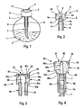
- FIGS. 1 to 5 are identified by identical reference numerals.
- FIG. 1 there is shown a bottle catalytic combustion 1 adapted to contain a combustible composition 2 and to receive, at its part superior, a combustion burner system catalytic converter 3 according to the invention.
- This bottle 1 can be of any shape and has a neck 4 adapted to receive the system of catalytic burner 3.
- the catalytic burner system 3 may be provided, at its lower part, with a support (no represented) allowing its introduction, either directly in the neck 4 of the bottle 1, in the central hole a base (not shown), the latter being adapted to be fixed at the neck 4 of the bottle 1.
- the fuel composition 2 is a liquid appropriate fuel, in accordance with the regulations force and adapted to catalytic combustion and vaporization.
- This combustible composition 2 may in particular be an alcohol, especially isopropyl alcohol, and may further comprise a scented material and / or active ingredient.
- This burner system 3 is formed of a burner catalytic combustion 5 and a sleeve 6, and is suitable to receive a wick 7 dipping in the composition fuel 2.
- the burner 5 has, at its lower part 5a, a cavity 8 substantially axial provided with the wick 7 for bringing to the burner 5 the fuel composition 2.
- the burner 5 has at its upper part 5b a peripheral zone 9, of annular shape, which supports a catalyst 10 and a central zone 11 without catalyst forming vaporization zone.
- This burner 5 is made in a first porous material suitable and resistant to temperatures of at least 400 ° C reached in the zone supporting the catalyst during operation of the burner.
- This material may especially be a material ceramic, and for example prepared from kaolin or of cordierite.
- the catalyst is for example a metal belonging to group VIII of the classification table periodic elements.
- the sleeve 6 of the combustion burner system catalytic converter 3 comprises a cavity 12 substantially axially adapted to grip the wick 7 (no shown in Figure 2) so that the combustible composition 2 can migrate pores from the upper portion 6a of the sleeve 6 to the pores of the lower part 5a of the burner 5.
- the sleeve 6 is arranged in the extension of the lower part 5a of the burner 5, so as to align substantially co-axially, on a part at less than its surface, the cavity 8 of the burner 5 with the cavity 12 of the sleeve 6.
- the sleeve 6 is made in one second porous material, which may especially be a material ceramic, for example prepared from kaolin or cordierite.
- the porosity of the second material porous is less than the porosity of the first porous material forming the burner 5.
- the first and second materials porous respectively of the burner 5 and the sleeve 6, are prepared from cordierite.
- the lower part 5a of the burner 5 and the part upper 6a of the sleeve 6 have shapes complementary to each other.
- parts 5a and 6a present a junction surface 13 planar.
- the burner 5 and the sleeve 6 are for example assembled by means of a porous seal adapted to ensure the migration of the fuel composition of the sleeve 6 to the burner 5.
- the burner 5 and the sleeve 6 constitute a single piece.
- the method of manufacturing the burner system is accordingly adapted to allow the realization, where appropriate, distinct porosities between the part of the system 3 corresponding to the burner 5 on the one hand and the part of the system 3 corresponding to the sleeve 6 else go.
- This burner system 30 comprises a burner catalytic combustion 35 and a sleeve 36 joined by nesting, preferably completed by sealing porous, at the bottom 35a of the burner 35 and the upper portion 36a of the sleeve 36.
- the cavity 42 of the sleeve 36 is located in the extension of the cavity 38 of the burner 35 and presents in the case shown in Figure 3 a section transverse lower than the cross section corresponding cavity 42 of the sleeve 36.
- the burner 35 has an annular groove 44 substantially axial extending from the surface 35c upper burner 35 and separating the zone peripheral 39 supporting the catalyst 10 of the zone central 41 without catalyst forming vaporization zone.
- the burner 35 further has a channel 45 for to vent the upper part 38a of the cavity 38 for receiving the wick.
- the channel 45 is formed substantially axially. However, nothing prohibits consideration of other provisions for this channel 45, especially the particular provision represented in FIG. 8 of WO 99/63267.
- FIG. 4 A third variant embodiment of a burner system according to the invention is shown in figure 4.
- the burner system 50 shown in FIG. 4 comprises a catalytic burner 55 and a sleeve 56.
- This sleeve 56 is arranged in the extension of the lower part 55a of the burner 55 and is in contact, at its upper part 56a, with the part lower 55a of the burner 55.
- This burner 55 has a frustoconical shape flared up.
- the upper part 55b of the burner 55 comprises a peripheral zone 59 carrying a catalyst 10 and surrounding a central area 61 without a catalyst, as well as that a cavity 58.
- This cavity 58 is connected to the atmosphere, level of its upper part 58a, through channel 65 located in the center of the central area 61.
- the cavity 62 of the sleeve 56 may have a cross section narrower than the section cross section of the cavity 58 of the burner 55.
- the cavity 62 of the sleeve 58 is here entirely filled by the wick 7 which does not penetrate into the cavity 58 of the burner 55.
- This particular frustoconical shape of the burner allows to increase the spray surface of the combustible composition and thus to ensure a better diffusion of this composition in the ambient air of a enclosure or room.
- the burner 55 may advantageously be provided with minus a shoulder 64 intended to delimit the part of the peripheral zone 59 which is intended to receive the catalyst 10.
- such a shoulder 64 cooperates with the sleeve 56 to allow an adjusted positioning of the burner system 50 according to the invention on the bottle 1 of Figure 1, at its neck 4.
- the wick 7 is any known wick, for example example a cotton wick.
- wick of mineral material such as a fiber wick mineral.
- the wick 7 is chosen so that its capillarity is much greater than the radial capillarity and longitudinal sleeve 6.
- the wick 7 is disposed in the bottle at catalytic combustion so as to soak in the fuel composition 2 and is maintained in the burner system 3, 30, 50, by its upper part 7a which is enclosed in the sleeve 6, 36, 56.
- the sleeve 6, 36, 56 covers at least 10%, generally between 10 and 40%, advantageously between 20 and 30%, and preferably of the order of 25% of the length of the wick 7.
- the size of the sleeve 6, 36, 56 depends on the time of the porosity of the second porous material forming the sleeve 6, 36, 56 and the degree of tightening of the wick 7 in said sleeve 6, 36, 56, in particular when the wick used is cotton.
- the wick 7 occupies the entire volume of the cavity 12, 42, 62 of the sleeve 6, 36, 56.
- said wick 7 also occupies all or part of the volume of the cavity 8, 38, 58 of the burner 5, 35, 55.
- the burner system 70 shown in FIG. comprises a catalytic combustion burner 75 and a sleeve 76 joined by sealing at the level of the part lower 75a of the burner 75 and the upper part 76a of the sleeve 76.
- the burner 75 has a peripheral zone supported 79 supporting a catalyst 10, this zone 79 surrounding a central zone 81 without catalyst.
- the burner 75 has a solid structure and presents no cavity at the level from its lower part 75a.
- This burner 75 is arranged on a support and / or base 71 fixed to the neck 4 of the bottle 1.
- the sleeve 76 occupies substantially the entire height of the bottle 1.
- the part lower 76b of the sleeve 76 is near the bottom 1a of the bottle 1.
- the sleeve 76 has a telescopic structure so that its length adapts to the different heights of the bottles on which the burner system 70 is intended to be used.
- combustion burner system catalytic converter 3, 30, 50, 70 namely the burner catalytic combustion 5, 35, 55, 75 and the sleeve 6, 36, 56, 76.
- the shape of the burner can be whatever, and should not be construed as only limited to cylindrical and frustoconical shapes represented.
Landscapes
- Life Sciences & Earth Sciences (AREA)
- Engineering & Computer Science (AREA)
- Pest Control & Pesticides (AREA)
- Health & Medical Sciences (AREA)
- General Health & Medical Sciences (AREA)
- Combustion & Propulsion (AREA)
- General Engineering & Computer Science (AREA)
- Mechanical Engineering (AREA)
- Chemical & Material Sciences (AREA)
- Public Health (AREA)
- Veterinary Medicine (AREA)
- Animal Behavior & Ethology (AREA)
- Epidemiology (AREA)
- Toxicology (AREA)
- Insects & Arthropods (AREA)
- Wood Science & Technology (AREA)
- Zoology (AREA)
- Environmental Sciences (AREA)
- Wick-Type Burners And Burners With Porous Materials (AREA)
- Gas Burners (AREA)
- Spray-Type Burners (AREA)
Claims (11)
- Brennersystem zur katalytischen Verbrennung, umfassend einen Brenner (5, 35, 55, 75) aus einem ersten porösen Material, der an seinem oberen Teil (5b, 35b, 55b, 75b) eine Umfangszone (9, 39, 59, 79), die einen Katalysator trägt (10), und eine Zentralzone (11, 41, 61, 81) ohne Katalysator, die eine Verdampfungszone bildet, aufweist, dadurch gekennzeichnet, dass dieses System (3, 30, 50, 70) ferner eine Hülse (6, 36, 56, 76) aus einem zweiten porösen Material umfasst, die einen im Wesentlichen axialen Hohlraum (12, 42, 62, 82) aufweist, der so ausgebildet ist, dass dieser einen Docht (7, 7a) einspannt, der dazu bestimmt ist, dem Brenner (5, 35, 55, 75) eine brennbare Zusammensetzung (2) zuzuführen, wobei die Hülse (6, 36, 56, 76) in der Verlängerung des unteren Teils (5a, 35a, 55a, 75a) des Brenners (5, 35, 55, 75) angeordnet ist, derart, dass die brennbare Zusammensetzung (2) aus den Poren des oberen Teils (6a, 36a, 56a, 76a) der Hülse (6, 36, 56, 76) in Richtung der Poren des unteren Teils (5a, 35a, 55a, 75a) des Brenners (5, 35, 55, 75) migrieren kann.
- System nach Anspruch 1, dadurch gekennzeichnet, dass die Porosität des zweiten porösen Materials der Hülse (6, 36, 56, 76) vorzugsweise geringer ist als die Porosität des ersten porösen Materials des Brenners (5, 35, 55, 75).
- System nach Anspruch 1 oder 2, dadurch gekennzeichnet, dass die Hülse (6, 36, 56, 76) wenigstens 10%, im Wesentlichen zwischen 10 und 40%, in vorteilhafter Weise zwischen 20 und 30% und vorzugsweise in der Größenordnung von 25% der Länge der Hülse (7, 7a) abdeckt.
- System nach einem der Ansprüche 1 bis 3, dadurch gekennzeichnet, dass der Brenner (5, 35, 55, 75) und die Hülse (6, 36, 56, 76) mit Hilfe einer porösen Einhüllung zusammen gebaut sind, die so ausgebildet ist, dass die Migration der brennbaren Zusammensetzung (2) der Hülse (6, 36, 56, 76) in Richtung des Brenners (5, 35, 55, 75) gewährleistet ist.
- System nach einem der Ansprüche 1 bis 3, dadurch gekennzeichnet, dass der Brenner (5, 35, 55, 75) und die Hülse (6, 36, 56, 76) ein einziges Stück bilden.
- System nach einem der Ansprüche 1 bis 5, dadurch gekennzeichnet, dass das erste und das zweite poröse Material aus Cordierit hergestellt sind.
- System nach einem der Ansprüche 1 bis 6, dadurch gekennzeichnet, dass der Brenner (35) eine im Wesentlichen axiale Ringkehle (44) aufweist, die sich bis zu der oberen Oberfläche (35c) des Brenners (35) erstreckt und die Umfangszone (39), welche den Katalysator (10) trägt, von der Zentralzone (41) ohne Katalysator, welche die Verdampfungszone bildet, trennt.
- System nach einem der Ansprüche 1 bis 7, dadurch gekennzeichnet, dass der Brenner (5, 35, 55) an seinem unteren Teil (5a, 35a, 55a) einen im Wesentlichen axialen Hohlraum (8, 38, 58) aufweist, der so ausgebildet ist, dass er den Docht (7, 7a) aufnehmen kann.
- System nach Anspruch 8, dadurch gekennzeichnet, dass der Brenner (35, 55) einen Kanal (45, 65) aufweist, um den oberen Teil (38a, 58a) des Hohlraums (38, 58), der den Docht (7, 7a) aufnimmt, mit der Atmosphäre zu verbinden.
- System nach Anspruch 7 oder 8, wobei das System (3, 30, 50) mit einem Docht (7, 7a) ausgestattet ist, dadurch gekennzeichnet, dass der Docht (7, 7a) in den im wesentlichen axialen Hohlraum (12, 42, 62) der Hülse (6, 36, 56) und gegebenenfalls ganz oder teilweise in dem im wesentlichen axialen Hohlraum (8, 38, 58) des Brenners (5, 35, 55) eingespannt ist.
- Kolben für eine katalytische Verbrennung, der so ausgebildet ist, dass dieser eine brennbare Zusammensetzung (2) aufnehmen kann und an seinem Hals (4) ein Brennersystem für eine katalytische Verbrennung (3, 30, 50, 70) aufnehmen kann, das so ausgebildet ist, dass dieses mit einem Docht (5) zusammen wirkt, der in die brennbare Zusammensetzung (2) eintaucht, dadurch gekennzeichnet, dass dieser mit einem Brennersystem (3, 30, 50, 70) gemäß einem der Ansprüche 1 bis 10 ausgestattet ist.
Applications Claiming Priority (2)
| Application Number | Priority Date | Filing Date | Title |
|---|---|---|---|
| FR0307767A FR2856776B1 (fr) | 2003-06-27 | 2003-06-27 | Systeme de bruleur a combustion catalytique et flacon equipe d'un tel systeme |
| FR0307767 | 2003-06-27 |
Publications (2)
| Publication Number | Publication Date |
|---|---|
| EP1491819A1 EP1491819A1 (de) | 2004-12-29 |
| EP1491819B1 true EP1491819B1 (de) | 2005-08-24 |
Family
ID=31985455
Family Applications (1)
| Application Number | Title | Priority Date | Filing Date |
|---|---|---|---|
| EP04291189A Expired - Lifetime EP1491819B1 (de) | 2003-06-27 | 2004-05-07 | Brennersystem mit katalytischer Verbrennung und Fläschchen mit einem solchen System |
Country Status (14)
| Country | Link |
|---|---|
| US (1) | US7137811B2 (de) |
| EP (1) | EP1491819B1 (de) |
| JP (1) | JP3814602B2 (de) |
| KR (1) | KR100569850B1 (de) |
| CN (1) | CN1273765C (de) |
| AT (1) | ATE302926T1 (de) |
| CA (1) | CA2469854C (de) |
| DE (2) | DE04291189T1 (de) |
| ES (1) | ES2238208T3 (de) |
| FR (1) | FR2856776B1 (de) |
| HK (1) | HK1056486A2 (de) |
| MY (1) | MY131844A (de) |
| SG (1) | SG120953A1 (de) |
| TW (1) | TWI229177B (de) |
Families Citing this family (11)
| Publication number | Priority date | Publication date | Assignee | Title |
|---|---|---|---|---|
| US20070202450A1 (en) * | 2006-02-08 | 2007-08-30 | The Board Of Regents, The University Of Texas System | Catalytic burner for combustion of liquid fuels |
| FR2905163B1 (fr) * | 2006-08-23 | 2008-10-17 | Prod Berger Soc Par Actions Si | Bruleur a combustion catalytique, dispositif de support pour bruleur, et ensemble bruleur-dispositif de bruleur avec events. |
| FR2905870B1 (fr) * | 2006-09-19 | 2012-03-09 | Europ Cosmetics | Diffuseur d'arome a combustion catalytique muni de recharge |
| CA2702099A1 (en) * | 2006-10-12 | 2008-04-17 | Stonewick, Inc. | Catalytic burner |
| US10041669B2 (en) * | 2006-10-12 | 2018-08-07 | Stonewick, Llc | Catalytic burner |
| FR2950257B1 (fr) | 2009-09-22 | 2012-01-20 | Prod Berger | Ensemble pour la diffusion d'une composition dans l'air |
| GB201321309D0 (en) * | 2013-12-03 | 2014-01-15 | Ashleigh & Burwood | A Catalytic fragrance burner assembly and a method of manufacture thereof |
| CN105570886A (zh) * | 2016-03-10 | 2016-05-11 | 桂林市淦隆环保科技有限公司 | 毛细陶瓷自吸式灯芯及火炉 |
| FR3061543B1 (fr) * | 2016-12-30 | 2019-08-23 | Produits Berger | Bruleur a combustion catalytique en materiau poreux a performances de fonctionnement optimisees et flacon equipe d'un tel bruleur |
| CN108844050A (zh) * | 2018-08-24 | 2018-11-20 | 无锡市疾病预防控制中心 | 一种灯芯及明火灯具 |
| FR3090420B1 (fr) * | 2018-12-21 | 2020-12-11 | Berger Produits | Procede de depot d’un catalyseur a la surface d’un bruleur a combustion catalytique |
Family Cites Families (14)
| Publication number | Priority date | Publication date | Assignee | Title |
|---|---|---|---|---|
| US2504584A (en) * | 1947-04-02 | 1950-04-18 | Pedro S Ramos | Composite wick |
| US3240256A (en) * | 1963-11-19 | 1966-03-15 | Canadian Patents Dev | Catalytic heater |
| JPS5543326A (en) * | 1978-09-21 | 1980-03-27 | Tokai:Kk | Plastic gas lighter |
| FR2483782A1 (fr) * | 1980-06-04 | 1981-12-11 | Auvray Philippe | Procede pour la diffusion atmospherique de produits actifs en phase gazeuse et dispositif pour la mise en oeuvre de ce procede |
| JPS5710610U (de) * | 1980-06-11 | 1982-01-20 | ||
| JPS5888510U (ja) * | 1981-12-10 | 1983-06-15 | シルバ−工業株式会社 | 燃焼器具用芯 |
| DE3436310A1 (de) * | 1984-10-03 | 1986-04-10 | Globol-Werk Gmbh, 8858 Neuburg | Verdampfervorrichtung fuer in feste traegermaterialien eingelagerte wirkstoffe, wie pyrethrum |
| FR2579465B1 (fr) * | 1985-03-27 | 1987-09-11 | Berger Sa Produits | Dispositif pour la diffusion atmospherique de produits actifs en phase gazeuse |
| FR2610390B1 (fr) * | 1987-01-29 | 1990-09-07 | Berger Sa Produits | Bruleur a combustion catalytique |
| US4781577A (en) * | 1987-03-26 | 1988-11-01 | Jeff Stewart | Fuel bottle with candle-like attachment |
| FR2680118B1 (fr) * | 1991-08-09 | 1995-02-10 | Senteurs Parfums Cie | Procede pour diffuser par catalyse un liquide combustible melange a un produit parfume, assainissant, deodorant, insecticide, expectoriant ou autre et diffuseur catalytique mettant en óoeuvre ce procede. |
| US6162046A (en) * | 1995-05-10 | 2000-12-19 | Allports Llc International | Liquid vaporization and pressurization apparatus and methods |
| FR2779509B1 (fr) * | 1998-06-04 | 2000-07-07 | Prod Berger | Bruleur a combustion catalytique en matiere poreuse et flacon equipe d'un tel bruleur |
| FR2818151B1 (fr) * | 2000-12-14 | 2004-04-02 | Prod Berger | Composition anti-bacterienne destinee a etre diffusee pour lutter contre les bacteries contenues dans l'air, procede de diffusion d'une telle composition |
-
2003
- 2003-06-27 FR FR0307767A patent/FR2856776B1/fr not_active Expired - Fee Related
- 2003-09-24 MY MYPI20033648A patent/MY131844A/en unknown
- 2003-09-26 TW TW092126704A patent/TWI229177B/zh not_active IP Right Cessation
- 2003-10-02 HK HK03107110A patent/HK1056486A2/xx not_active IP Right Cessation
- 2003-10-09 KR KR1020030070296A patent/KR100569850B1/ko not_active Expired - Fee Related
- 2003-10-10 CN CNB200310100651XA patent/CN1273765C/zh not_active Expired - Fee Related
- 2003-10-10 JP JP2003352050A patent/JP3814602B2/ja not_active Expired - Fee Related
- 2003-10-10 SG SG200305936A patent/SG120953A1/en unknown
-
2004
- 2004-05-07 ES ES04291189T patent/ES2238208T3/es not_active Expired - Lifetime
- 2004-05-07 DE DE04291189T patent/DE04291189T1/de active Pending
- 2004-05-07 AT AT04291189T patent/ATE302926T1/de active
- 2004-05-07 DE DE602004000062T patent/DE602004000062T2/de not_active Expired - Lifetime
- 2004-05-07 EP EP04291189A patent/EP1491819B1/de not_active Expired - Lifetime
- 2004-05-13 CA CA002469854A patent/CA2469854C/fr not_active Expired - Fee Related
- 2004-06-08 US US10/863,481 patent/US7137811B2/en not_active Expired - Lifetime
Also Published As
| Publication number | Publication date |
|---|---|
| TW200500573A (en) | 2005-01-01 |
| US20040265762A1 (en) | 2004-12-30 |
| DE602004000062T2 (de) | 2006-02-16 |
| FR2856776A1 (fr) | 2004-12-31 |
| HK1056486A2 (en) | 2004-01-30 |
| JP3814602B2 (ja) | 2006-08-30 |
| SG120953A1 (en) | 2006-04-26 |
| ATE302926T1 (de) | 2005-09-15 |
| US7137811B2 (en) | 2006-11-21 |
| EP1491819A1 (de) | 2004-12-29 |
| KR20050005707A (ko) | 2005-01-14 |
| CA2469854C (fr) | 2008-11-04 |
| CN1576692A (zh) | 2005-02-09 |
| KR100569850B1 (ko) | 2006-04-11 |
| CA2469854A1 (fr) | 2004-12-27 |
| ES2238208T1 (es) | 2005-09-01 |
| HK1072801A1 (en) | 2005-09-09 |
| ES2238208T3 (es) | 2006-03-16 |
| DE04291189T1 (de) | 2005-06-23 |
| FR2856776B1 (fr) | 2005-08-19 |
| JP2005016926A (ja) | 2005-01-20 |
| MY131844A (en) | 2007-09-28 |
| DE602004000062D1 (de) | 2005-09-29 |
| CN1273765C (zh) | 2006-09-06 |
| TWI229177B (en) | 2005-03-11 |
Similar Documents
| Publication | Publication Date | Title |
|---|---|---|
| EP1491819B1 (de) | Brennersystem mit katalytischer Verbrennung und Fläschchen mit einem solchen System | |
| CA2331353C (fr) | Bruleur poreux a combustion catalytique et flacon equipe d'un tel bruleur | |
| EP1491818B1 (de) | Brenner mit katalytischer Verbrennung in porösem Material und mit einem solchen Brenner ausgerüstete Flasche | |
| EP0516538B1 (de) | Flüssigkeitschreibgerät mit einem mikroporösen Pufferbehälter | |
| EP2558131A1 (de) | Duftstoff-umkehrzerstäuber | |
| FR2952040A1 (fr) | Dispositif de distribution de liquide sous forme de gouttes | |
| EP2905035A1 (de) | Vorrichtung zur Zerstäubung eines Duftstoffs mit einer Vielzahl von Öffnungen | |
| EP2054667B1 (de) | Zusammensetzung aus siliciumcarbid für einen katalytischen verbrenner aus porösem material | |
| EP2054666B1 (de) | Katalytischer brenner mit spezialspitze und mit einem solchen brenner ausgestattete flasche | |
| FR2680118A1 (fr) | Procede pour diffuser par catalyse un liquide combustible melange a un produit parfume, assainissant, deodorant, insecticide, expectoriant ou autre et diffuseur catalytique mettant en óoeuvre ce procede. | |
| EP3563086B1 (de) | Aus einem porösen material hergestellter, katalytischer verbrenner mit optimierter betriebsleistungen und mit solch einem verbrenner ausgestattete flasche | |
| EP0500663A1 (de) | Verdunstungseinrichtung für flüssigkeiten aus einer absorbierenden porösen substanz | |
| EP3899368B1 (de) | Verfahren zur abscheidung eines katalysators auf der oberfläche eines katalytischen verbrennungsbrenners | |
| EP3563087B1 (de) | Katalytischer verbrenner aus einem porösen material mit optimierter betriebsleistungen und mit solch einem brenner ausgestattete flasche | |
| EP1180073A1 (de) | Schreibspitze und verfahren zur behandlung eines länglichen elementes für die herstellung einer solchen schreibspitze | |
| FR3037510A1 (fr) | Distributeur a applicateur impregnable. | |
| BE1019337A5 (fr) | Buche de bois destinee a produire de la chaleur et de l'eclairage. | |
| WO2011036408A1 (fr) | Ensemble pour la diffusion d'une composition dans l'air | |
| FR3115699A1 (fr) | Dispositif et procédé pour diffuser une substance odorante dans l’air | |
| FR2732669A1 (fr) | Dispositif de regulation automatique de la pression a l'interieur d'un conteneur manipulable renfermant un liquide et conteneur equipe d'un tel dispositif | |
| FR2780137A1 (fr) | Torche et procede pour son obtention | |
| FR2798723A1 (fr) | Regulateur de combustion de bougies avec ou sans meche incorporee | |
| FR2759766A1 (fr) | Lampe a combustible liquide en forme de bougie |
Legal Events
| Date | Code | Title | Description |
|---|---|---|---|
| PUAI | Public reference made under article 153(3) epc to a published international application that has entered the european phase |
Free format text: ORIGINAL CODE: 0009012 |
|
| AK | Designated contracting states |
Kind code of ref document: A1 Designated state(s): AT BE BG CH CY CZ DE DK EE ES FI FR GB GR HU IE IT LI LU MC NL PL PT RO SE SI SK TR |
|
| AX | Request for extension of the european patent |
Extension state: AL HR LT LV MK |
|
| GRAP | Despatch of communication of intention to grant a patent |
Free format text: ORIGINAL CODE: EPIDOSNIGR1 |
|
| 17P | Request for examination filed |
Effective date: 20041216 |
|
| TCNL | Nl: translation of patent claims filed | ||
| GBC | Gb: translation of claims filed (gb section 78(7)/1977) | ||
| TCAT | At: translation of patent claims filed | ||
| GRAS | Grant fee paid |
Free format text: ORIGINAL CODE: EPIDOSNIGR3 |
|
| DET | De: translation of patent claims | ||
| GRAA | (expected) grant |
Free format text: ORIGINAL CODE: 0009210 |
|
| AK | Designated contracting states |
Kind code of ref document: B1 Designated state(s): AT BE BG CH CY CZ DE DK EE ES FI FR GB GR HU IE IT LI LU MC NL PL PT RO SE SI SK TR |
|
| PG25 | Lapsed in a contracting state [announced via postgrant information from national office to epo] |
Ref country code: PL Free format text: LAPSE BECAUSE OF FAILURE TO SUBMIT A TRANSLATION OF THE DESCRIPTION OR TO PAY THE FEE WITHIN THE PRESCRIBED TIME-LIMIT Effective date: 20050824 Ref country code: SK Free format text: LAPSE BECAUSE OF FAILURE TO SUBMIT A TRANSLATION OF THE DESCRIPTION OR TO PAY THE FEE WITHIN THE PRESCRIBED TIME-LIMIT Effective date: 20050824 Ref country code: FI Free format text: LAPSE BECAUSE OF FAILURE TO SUBMIT A TRANSLATION OF THE DESCRIPTION OR TO PAY THE FEE WITHIN THE PRESCRIBED TIME-LIMIT Effective date: 20050824 Ref country code: SI Free format text: LAPSE BECAUSE OF FAILURE TO SUBMIT A TRANSLATION OF THE DESCRIPTION OR TO PAY THE FEE WITHIN THE PRESCRIBED TIME-LIMIT Effective date: 20050824 Ref country code: RO Free format text: LAPSE BECAUSE OF FAILURE TO SUBMIT A TRANSLATION OF THE DESCRIPTION OR TO PAY THE FEE WITHIN THE PRESCRIBED TIME-LIMIT Effective date: 20050824 Ref country code: CZ Free format text: LAPSE BECAUSE OF FAILURE TO SUBMIT A TRANSLATION OF THE DESCRIPTION OR TO PAY THE FEE WITHIN THE PRESCRIBED TIME-LIMIT Effective date: 20050824 |
|
| REG | Reference to a national code |
Ref country code: GB Ref legal event code: FG4D Free format text: NOT ENGLISH |
|
| REG | Reference to a national code |
Ref country code: CH Ref legal event code: EP |
|
| GBT | Gb: translation of ep patent filed (gb section 77(6)(a)/1977) |
Effective date: 20050824 |
|
| AKX | Designation fees paid |
Designated state(s): AT BE BG CH CY CZ DE DK EE ES FI FR GB GR HU IE IT LI LU MC NL PL PT RO SE SI SK TR |
|
| REG | Reference to a national code |
Ref country code: IE Ref legal event code: FG4D Free format text: LANGUAGE OF EP DOCUMENT: FRENCH |
|
| REF | Corresponds to: |
Ref document number: 602004000062 Country of ref document: DE Date of ref document: 20050929 Kind code of ref document: P |
|
| REG | Reference to a national code |
Ref country code: CH Ref legal event code: NV Representative=s name: WILLIAM BLANC & CIE CONSEILS EN PROPRIETE INDUSTRI |
|
| PG25 | Lapsed in a contracting state [announced via postgrant information from national office to epo] |
Ref country code: SE Free format text: LAPSE BECAUSE OF FAILURE TO SUBMIT A TRANSLATION OF THE DESCRIPTION OR TO PAY THE FEE WITHIN THE PRESCRIBED TIME-LIMIT Effective date: 20051124 Ref country code: GR Free format text: LAPSE BECAUSE OF FAILURE TO SUBMIT A TRANSLATION OF THE DESCRIPTION OR TO PAY THE FEE WITHIN THE PRESCRIBED TIME-LIMIT Effective date: 20051124 Ref country code: BG Free format text: LAPSE BECAUSE OF FAILURE TO SUBMIT A TRANSLATION OF THE DESCRIPTION OR TO PAY THE FEE WITHIN THE PRESCRIBED TIME-LIMIT Effective date: 20051124 Ref country code: DK Free format text: LAPSE BECAUSE OF FAILURE TO SUBMIT A TRANSLATION OF THE DESCRIPTION OR TO PAY THE FEE WITHIN THE PRESCRIBED TIME-LIMIT Effective date: 20051124 |
|
| PG25 | Lapsed in a contracting state [announced via postgrant information from national office to epo] |
Ref country code: HU Free format text: LAPSE BECAUSE OF FAILURE TO SUBMIT A TRANSLATION OF THE DESCRIPTION OR TO PAY THE FEE WITHIN THE PRESCRIBED TIME-LIMIT Effective date: 20060225 |
|
| REG | Reference to a national code |
Ref country code: ES Ref legal event code: FG2A Ref document number: 2238208 Country of ref document: ES Kind code of ref document: T3 |
|
| PLBE | No opposition filed within time limit |
Free format text: ORIGINAL CODE: 0009261 |
|
| STAA | Information on the status of an ep patent application or granted ep patent |
Free format text: STATUS: NO OPPOSITION FILED WITHIN TIME LIMIT |
|
| 26N | No opposition filed |
Effective date: 20060526 |
|
| PG25 | Lapsed in a contracting state [announced via postgrant information from national office to epo] |
Ref country code: EE Free format text: LAPSE BECAUSE OF FAILURE TO SUBMIT A TRANSLATION OF THE DESCRIPTION OR TO PAY THE FEE WITHIN THE PRESCRIBED TIME-LIMIT Effective date: 20050824 |
|
| PG25 | Lapsed in a contracting state [announced via postgrant information from national office to epo] |
Ref country code: TR Free format text: LAPSE BECAUSE OF FAILURE TO SUBMIT A TRANSLATION OF THE DESCRIPTION OR TO PAY THE FEE WITHIN THE PRESCRIBED TIME-LIMIT Effective date: 20050824 |
|
| PG25 | Lapsed in a contracting state [announced via postgrant information from national office to epo] |
Ref country code: CY Free format text: LAPSE BECAUSE OF FAILURE TO SUBMIT A TRANSLATION OF THE DESCRIPTION OR TO PAY THE FEE WITHIN THE PRESCRIBED TIME-LIMIT Effective date: 20050824 |
|
| REG | Reference to a national code |
Ref country code: CH Ref legal event code: PFA Owner name: PRODUITS BERGER Free format text: PRODUITS BERGER#67, AVENUE VICTOR HUGO#75116 PARIS (FR) -TRANSFER TO- PRODUITS BERGER#67, AVENUE VICTOR HUGO#75116 PARIS (FR) |
|
| REG | Reference to a national code |
Ref country code: CH Ref legal event code: PCAR Free format text: NOVAGRAAF SWITZERLAND SA;CHEMIN DE L'ECHO 3;1213 ONEX (CH) |
|
| PGFP | Annual fee paid to national office [announced via postgrant information from national office to epo] |
Ref country code: LU Payment date: 20110531 Year of fee payment: 8 Ref country code: MC Payment date: 20110427 Year of fee payment: 8 |
|
| PGFP | Annual fee paid to national office [announced via postgrant information from national office to epo] |
Ref country code: CH Payment date: 20120514 Year of fee payment: 9 Ref country code: IE Payment date: 20120510 Year of fee payment: 9 Ref country code: NL Payment date: 20120515 Year of fee payment: 9 |
|
| PGFP | Annual fee paid to national office [announced via postgrant information from national office to epo] |
Ref country code: BE Payment date: 20120531 Year of fee payment: 9 |
|
| PG25 | Lapsed in a contracting state [announced via postgrant information from national office to epo] |
Ref country code: MC Free format text: LAPSE BECAUSE OF NON-PAYMENT OF DUE FEES Effective date: 20120531 |
|
| PGFP | Annual fee paid to national office [announced via postgrant information from national office to epo] |
Ref country code: ES Payment date: 20120607 Year of fee payment: 9 |
|
| PGFP | Annual fee paid to national office [announced via postgrant information from national office to epo] |
Ref country code: PT Payment date: 20120504 Year of fee payment: 9 |
|
| PGFP | Annual fee paid to national office [announced via postgrant information from national office to epo] |
Ref country code: AT Payment date: 20120426 Year of fee payment: 9 |
|
| REG | Reference to a national code |
Ref country code: PT Ref legal event code: MM4A Free format text: LAPSE DUE TO NON-PAYMENT OF FEES Effective date: 20131107 |
|
| BERE | Be: lapsed |
Owner name: *PRODUITS BERGER Effective date: 20130531 |
|
| REG | Reference to a national code |
Ref country code: NL Ref legal event code: V1 Effective date: 20131201 |
|
| REG | Reference to a national code |
Ref country code: CH Ref legal event code: PL |
|
| REG | Reference to a national code |
Ref country code: AT Ref legal event code: MM01 Ref document number: 302926 Country of ref document: AT Kind code of ref document: T Effective date: 20130531 |
|
| PG25 | Lapsed in a contracting state [announced via postgrant information from national office to epo] |
Ref country code: AT Free format text: LAPSE BECAUSE OF NON-PAYMENT OF DUE FEES Effective date: 20130531 Ref country code: LI Free format text: LAPSE BECAUSE OF NON-PAYMENT OF DUE FEES Effective date: 20130531 Ref country code: CH Free format text: LAPSE BECAUSE OF NON-PAYMENT OF DUE FEES Effective date: 20130531 Ref country code: PT Free format text: LAPSE BECAUSE OF NON-PAYMENT OF DUE FEES Effective date: 20131107 |
|
| REG | Reference to a national code |
Ref country code: IE Ref legal event code: MM4A |
|
| PG25 | Lapsed in a contracting state [announced via postgrant information from national office to epo] |
Ref country code: NL Free format text: LAPSE BECAUSE OF NON-PAYMENT OF DUE FEES Effective date: 20131201 Ref country code: BE Free format text: LAPSE BECAUSE OF NON-PAYMENT OF DUE FEES Effective date: 20130531 |
|
| PG25 | Lapsed in a contracting state [announced via postgrant information from national office to epo] |
Ref country code: IE Free format text: LAPSE BECAUSE OF NON-PAYMENT OF DUE FEES Effective date: 20130507 |
|
| PG25 | Lapsed in a contracting state [announced via postgrant information from national office to epo] |
Ref country code: LU Free format text: LAPSE BECAUSE OF NON-PAYMENT OF DUE FEES Effective date: 20120507 |
|
| REG | Reference to a national code |
Ref country code: ES Ref legal event code: FD2A Effective date: 20140610 |
|
| PG25 | Lapsed in a contracting state [announced via postgrant information from national office to epo] |
Ref country code: ES Free format text: LAPSE BECAUSE OF NON-PAYMENT OF DUE FEES Effective date: 20130508 |
|
| PG25 | Lapsed in a contracting state [announced via postgrant information from national office to epo] |
Ref country code: IT Free format text: LAPSE BECAUSE OF NON-PAYMENT OF DUE FEES Effective date: 20150507 |
|
| REG | Reference to a national code |
Ref country code: FR Ref legal event code: PLFP Year of fee payment: 13 |
|
| REG | Reference to a national code |
Ref country code: FR Ref legal event code: PLFP Year of fee payment: 14 |
|
| PG25 | Lapsed in a contracting state [announced via postgrant information from national office to epo] |
Ref country code: IT Free format text: LAPSE BECAUSE OF NON-PAYMENT OF DUE FEES Effective date: 20150507 |
|
| PGRI | Patent reinstated in contracting state [announced from national office to epo] |
Ref country code: IT Effective date: 20170616 |
|
| REG | Reference to a national code |
Ref country code: FR Ref legal event code: PLFP Year of fee payment: 15 |
|
| PGFP | Annual fee paid to national office [announced via postgrant information from national office to epo] |
Ref country code: DE Payment date: 20200528 Year of fee payment: 17 |
|
| PGFP | Annual fee paid to national office [announced via postgrant information from national office to epo] |
Ref country code: IT Payment date: 20200528 Year of fee payment: 17 Ref country code: GB Payment date: 20200528 Year of fee payment: 17 |
|
| PGFP | Annual fee paid to national office [announced via postgrant information from national office to epo] |
Ref country code: FR Payment date: 20210528 Year of fee payment: 18 |
|
| REG | Reference to a national code |
Ref country code: DE Ref legal event code: R119 Ref document number: 602004000062 Country of ref document: DE |
|
| GBPC | Gb: european patent ceased through non-payment of renewal fee |
Effective date: 20210507 |
|
| PG25 | Lapsed in a contracting state [announced via postgrant information from national office to epo] |
Ref country code: GB Free format text: LAPSE BECAUSE OF NON-PAYMENT OF DUE FEES Effective date: 20210507 Ref country code: DE Free format text: LAPSE BECAUSE OF NON-PAYMENT OF DUE FEES Effective date: 20211201 |
|
| PG25 | Lapsed in a contracting state [announced via postgrant information from national office to epo] |
Ref country code: FR Free format text: LAPSE BECAUSE OF NON-PAYMENT OF DUE FEES Effective date: 20220531 |
|
| PG25 | Lapsed in a contracting state [announced via postgrant information from national office to epo] |
Ref country code: IT Free format text: LAPSE BECAUSE OF NON-PAYMENT OF DUE FEES Effective date: 20210531 |