EP1491771A1 - Device for determining the actual position of an actuator - Google Patents
Device for determining the actual position of an actuator Download PDFInfo
- Publication number
- EP1491771A1 EP1491771A1 EP04103012A EP04103012A EP1491771A1 EP 1491771 A1 EP1491771 A1 EP 1491771A1 EP 04103012 A EP04103012 A EP 04103012A EP 04103012 A EP04103012 A EP 04103012A EP 1491771 A1 EP1491771 A1 EP 1491771A1
- Authority
- EP
- European Patent Office
- Prior art keywords
- drive
- drive member
- potentiometer
- permanent magnet
- current position
- Prior art date
- Legal status (The legal status is an assumption and is not a legal conclusion. Google has not performed a legal analysis and makes no representation as to the accuracy of the status listed.)
- Granted
Links
Images

Classifications
-
- G—PHYSICS
- G01—MEASURING; TESTING
- G01D—MEASURING NOT SPECIALLY ADAPTED FOR A SPECIFIC VARIABLE; ARRANGEMENTS FOR MEASURING TWO OR MORE VARIABLES NOT COVERED IN A SINGLE OTHER SUBCLASS; TARIFF METERING APPARATUS; MEASURING OR TESTING NOT OTHERWISE PROVIDED FOR
- G01D5/00—Mechanical means for transferring the output of a sensing member; Means for converting the output of a sensing member to another variable where the form or nature of the sensing member does not constrain the means for converting; Transducers not specially adapted for a specific variable
- G01D5/12—Mechanical means for transferring the output of a sensing member; Means for converting the output of a sensing member to another variable where the form or nature of the sensing member does not constrain the means for converting; Transducers not specially adapted for a specific variable using electric or magnetic means
- G01D5/14—Mechanical means for transferring the output of a sensing member; Means for converting the output of a sensing member to another variable where the form or nature of the sensing member does not constrain the means for converting; Transducers not specially adapted for a specific variable using electric or magnetic means influencing the magnitude of a current or voltage
- G01D5/16—Mechanical means for transferring the output of a sensing member; Means for converting the output of a sensing member to another variable where the form or nature of the sensing member does not constrain the means for converting; Transducers not specially adapted for a specific variable using electric or magnetic means influencing the magnitude of a current or voltage by varying resistance
- G01D5/165—Mechanical means for transferring the output of a sensing member; Means for converting the output of a sensing member to another variable where the form or nature of the sensing member does not constrain the means for converting; Transducers not specially adapted for a specific variable using electric or magnetic means influencing the magnitude of a current or voltage by varying resistance by relative movement of a point of contact or actuation and a resistive track
-
- F—MECHANICAL ENGINEERING; LIGHTING; HEATING; WEAPONS; BLASTING
- F15—FLUID-PRESSURE ACTUATORS; HYDRAULICS OR PNEUMATICS IN GENERAL
- F15B—SYSTEMS ACTING BY MEANS OF FLUIDS IN GENERAL; FLUID-PRESSURE ACTUATORS, e.g. SERVOMOTORS; DETAILS OF FLUID-PRESSURE SYSTEMS, NOT OTHERWISE PROVIDED FOR
- F15B15/00—Fluid-actuated devices for displacing a member from one position to another; Gearing associated therewith
- F15B15/20—Other details, e.g. assembly with regulating devices
- F15B15/28—Means for indicating the position, e.g. end of stroke
- F15B15/2815—Position sensing, i.e. means for continuous measurement of position, e.g. LVDT
- F15B15/2853—Position sensing, i.e. means for continuous measurement of position, e.g. LVDT using potentiometers
-
- F—MECHANICAL ENGINEERING; LIGHTING; HEATING; WEAPONS; BLASTING
- F15—FLUID-PRESSURE ACTUATORS; HYDRAULICS OR PNEUMATICS IN GENERAL
- F15B—SYSTEMS ACTING BY MEANS OF FLUIDS IN GENERAL; FLUID-PRESSURE ACTUATORS, e.g. SERVOMOTORS; DETAILS OF FLUID-PRESSURE SYSTEMS, NOT OTHERWISE PROVIDED FOR
- F15B15/00—Fluid-actuated devices for displacing a member from one position to another; Gearing associated therewith
- F15B15/20—Other details, e.g. assembly with regulating devices
- F15B15/28—Means for indicating the position, e.g. end of stroke
- F15B15/2815—Position sensing, i.e. means for continuous measurement of position, e.g. LVDT
- F15B15/2861—Position sensing, i.e. means for continuous measurement of position, e.g. LVDT using magnetic means
Definitions
- the current position of the drive member inside the cylinder tube can be read optically as a closed drive housing.
- the invention includes the technical teaching that the means for detecting the current position of the drive member comprise a potentiometer foil element arranged in the magnetic effective range of the permanent magnet of the drive member and along its travel path or angle of rotation, the contact electrode of which runs axially parallel to the drive member and via the magnetic force of the permanent magnet can be operated locally concentrated.
- a potentiometer film element which is suitable for use in the present invention, can be seen, for example, from DE 43 35 004 C2.
- the potentiometer foil element consists of a lower support on which a resistance path is applied.
- An upper support is provided, on which a contact electrode following the path of the resistance section is applied, which is separated from the resistance section by an insulating frame at the electrical insulation distance and can be brought into electrical connection with the resistance section by pressing on the upper support.
- Corresponding electrical connection poles are provided at the ends of the resistance path and on the contact electrode, so that the electrical resistance, which changes due to the pressing of the upper carrier, can be determined as the location of the pressing point via appropriate evaluation electronics.
- a fluid suitably enclosed in a container can also be used.
Abstract
Description
Die vorliegende Erfindung betrifft eine Einrichtung zur Ermittlung der aktuellen Stellung eines Antriebsgliedes entlang des Hubwegs oder Drehwinkels, insbesondere bei einem druckmittelbetriebenen Linear- bzw. Drehantrieb, das innerhalb eines Antriebsgehäuses durch Druckmittelbeaufschlagung bewegbar untergebracht ist, wobei das Antriebsglied einen Permanentmagneten zum magnetischen Zusammenwirken mit außerhalb oder am LK:The present invention relates to a device for determining the current position of a drive member along the stroke or angle of rotation, in particular in the case of a pressure-medium-operated linear or rotary drive, which is movably accommodated within a drive housing by the application of pressure medium, the drive element being a permanent magnet for magnetic interaction with outside or at the LK:
Antriebsgehäuse angeordneten Mitteln zur Detektion der aktuellen Stellung des Antriebsgliedes aufweist.Drive housing arranged means for detecting the current position of the drive member.
Das Einsatzgebiet der Erfindung erstreckt sich auf den Bereich der Automatisierungstechnik. Beispielsweise bei Pneumatikzylindem, als automatisierungstechnische Komponenten wird die aktuelle Stellung des Kolbens als Antriebsglied detektiert, um einer übergeordneten elektronischen Steuereinheit die Information darüber zu vermitteln, in welcher Ausfahrstellung sich die Kolbenstange des Pneumatikzylinders in Ergebnis einer Druckmittelbeaufschlagung befindet. Mit dieser steuerungstechnischen Information wird der Pneumatikzylinder innerhalb eines Automatisierungssystems koordiniert betrieben.The field of application of the invention extends to the field of automation technology. For example, in the case of pneumatic cylinders, as automation components, the current position of the piston as the drive element is detected in order to convey to a higher-level electronic control unit the information in which extended position the piston rod of the pneumatic cylinder is as a result of pressure medium being applied. With this control-related information, the pneumatic cylinder is operated in a coordinated manner within an automation system.
Aus der DE 38 03 268 A1 geht eine gattungsgemäße Einrichtung hervor. Diese besteht im wesentlichen aus einem pneumatischen oder hydraulischen Arbeitszylinder, dessen Zylinderrohr aus einem unmagnetischen Material hergestellt ist und dessen Kolben als Arbeitsglied einen in Achsrichtung der Kolbenstange polarisierten Permanentmagneten aufweist. An der Außenwand des Zylinderrohres ist im Bereich des Druckraums ein weiterer Permanentmagnet vorgesehen, der in einem Gehäuse untergebracht ist, in dem ein Läufer bewegbar ist. Der Läufer weist einen Permanentmagneten auf, der mit dem Permanentmagneten des Kolbens magnetisch gekoppelt ist. Aufgrund dieser magnetischen Kopplung wird die Bewegung des Kolbens synchron auf den Läufer übertragen, der die jeweilige Stellung des Kolbens mit Hilfe eines Zeigers an einem Messstab anzeigt. An der Stellung des Zeigers ist optisch die aktuelle Stellung des Antriebsgliedes innerhalb des Zylinderrohres als geschlossenes Antriebsgehäuses ablesbar. Gemäß einer weiteren Ausführungsform wird hier vorgeschlagen, den Zeiger mit einem Schleifer eines linearverstellbaren herkömmlichen Potentiometers zu koppeln, um ein die aktuelle Stellung des Kolbens repräsentierendes elektrisches Signal zu gewinnen, welches mit einer elektronischen Steuereinheit entsprechend auswertbar und weiterverarbeitbar ist.DE 38 03 268 A1 shows a generic device. This consists essentially of a pneumatic or hydraulic working cylinder, the cylinder tube of which is made of a non-magnetic material and the piston of which has a permanent magnet polarized in the axial direction of the piston rod as the working member. A further permanent magnet is provided on the outer wall of the cylinder tube in the area of the pressure chamber and is accommodated in a housing in which a rotor can be moved. The rotor has a permanent magnet which is magnetically coupled to the permanent magnet of the piston. Because of this magnetic coupling, the movement of the piston is transmitted synchronously to the rotor, which indicates the respective position of the piston with the aid of a pointer on a measuring rod. At the position of the pointer, the current position of the drive member inside the cylinder tube can be read optically as a closed drive housing. According to a further embodiment, it is proposed here to couple the pointer with a slider of a linearly adjustable conventional potentiometer in order to obtain an electrical signal representing the current position of the piston, which signal can be correspondingly evaluated and further processed with an electronic control unit.
Ein Nachteil dieser Lösung besteht jedoch darin, dass eine solche Kombination eines magnetischen Läufers mit einem herkömmlichen Linear-Potentiometer einen recht großen Bauraum erfordert. Weiterhin kann es im Verbindungsbereich zwischen dem magnetischen Läufer und dem Schleifer des Linear-Potentiometers zu mechanischen Verklemmungen und damit zum Ausfall dieses mechanischen Wegmesssystems kommen.A disadvantage of this solution, however, is that such a combination of a magnetic rotor with a conventional linear potentiometer requires a very large amount of space. Furthermore, mechanical jamming can occur in the connection area between the magnetic rotor and the slider of the linear potentiometer, and thus failure of this mechanical position measuring system.
Es ist daher die Aufgabe der vorliegenden Erfindung eine Einrichtung zur Ermittlung der aktuellen Stellung eines Antriebsgliedes entlang des Hubweges oder Drehwinkels zu schaffen, die mit einfachen technischen Mitteln bauraumsparend eine zuverlässige Wegmessung gewährleistet.It is therefore the object of the present invention to provide a device for determining the current position of a drive element along the stroke or angle of rotation, which ensures reliable displacement measurement with simple technical means in a space-saving manner.
Die Aufgabe wird ausgehend von einer Einrichtung gemäß dem Oberbegriff des Anspruchs 1 in Verbindung mit dessen kennzeichnenden Merkmalen gelöst. Die nachfolgenden abhängigen Ansprüche geben vorteilhafte Weiterbildungen der Erfindung wieder.The object is achieved on the basis of a device according to the preamble of claim 1 in conjunction with its characterizing features. The following dependent claims represent advantageous developments of the invention.
Die Erfindung schließt die technische Lehre ein, dass die Mittel zur Detektion der aktuellen Stellung des Antriebgliedes ein im magnetischen Wirkbereich des Permanentmagneten des Antriebsgliedes und entlang dessen Hubwegs bzw. Drehwinkels angeordnetes Potentiometerfolienelement umfassen, dessen Kontaktelektrode achsparallel zum Antriebsglied verläuft und über die magnetische Kraft des Permanentmagneten örtlich konzentriert betätigbar ist.The invention includes the technical teaching that the means for detecting the current position of the drive member comprise a potentiometer foil element arranged in the magnetic effective range of the permanent magnet of the drive member and along its travel path or angle of rotation, the contact electrode of which runs axially parallel to the drive member and via the magnetic force of the permanent magnet can be operated locally concentrated.
Der Vorteil der erfindungsgemäßen Lösung liegt insbesondere darin, dass mit dem flachbauenden Potentiometerfolienelement eine besonders bauraumsparende Lösung zur Wegmessung darstellbar ist. Das Potentiometerfolienelement kann direkt durch den im Antriebsglied integrierten Permanentmagneten örtlich konzentriert betätigt werden. Damit entfallen gleitreibungsbehaftete zwischengeschaltete Bauelemente im Betätigungskraftfluss, so dass ein Verklemmen von Komponenten der Wegmesseinrichtung nicht zu befürchten ist.The advantage of the solution according to the invention is, in particular, that a particularly space-saving solution for path measurement can be represented with the flat-construction potentiometer film element. The potentiometer foil element can be actuated locally concentrated by the permanent magnet integrated in the drive member. Intermediate components with sliding friction in the actuation force flow are thus eliminated, so that there is no fear of jamming of components of the displacement measuring device.
Ein Potentiometerfolienelement, was sich zum Einsatz bei der vorliegenden Erfindung eignet, geht an sich beispielsweise aus der DE 43 35 004 C2 hervor. Das Potentiometerfolienelement besteht aus einem unteren Träger, auf dem eine Widerstandsstrecke aufgebracht ist. Ein oberer Träger ist vorgesehen, auf dem eine dem Bahnverlauf der Widerstandsstrecke folgende Kontaktelektrode aufgebracht ist, die der Widerstandsstrecke getrennt durch einen Isolierrahmen im elektrischen Isolierabstand gegenüberliegt und durch Andrücken des oberen Trägers mit der Widerstandsstrecke in elektrische Verbindung bringbar ist. Entsprechende elektrische Anschlusspole an den Enden der Widerstandsstrecke sowie an der Kontaktelektrode sind vorgesehen, so dass anhand der durch Andrücken des oberen Trägers sich ändernde elektrische Widerstand als Ort des Andrückpunktes über eine entsprechende Auswertelektronik erfassbar ist.A potentiometer film element, which is suitable for use in the present invention, can be seen, for example, from DE 43 35 004 C2. The potentiometer foil element consists of a lower support on which a resistance path is applied. An upper support is provided, on which a contact electrode following the path of the resistance section is applied, which is separated from the resistance section by an insulating frame at the electrical insulation distance and can be brought into electrical connection with the resistance section by pressing on the upper support. Corresponding electrical connection poles are provided at the ends of the resistance path and on the contact electrode, so that the electrical resistance, which changes due to the pressing of the upper carrier, can be determined as the location of the pressing point via appropriate evaluation electronics.
Erfindungsgemäß erfolgt die Betätigung, d. h. dass das Andrücken der Kontaktelektrode an die Widerstandsbahn, magnetisch, nämlich durch den im Antriebsglied eingelassenen Permanentmagneten.According to the invention, the actuation takes place. H. that the contact electrode is pressed onto the resistance track, magnetically, namely by the permanent magnet embedded in the drive member.
Zur Verstärkung der die Kontaktelektrode des Potentiometerfolienelements betätigenden magnetischen Kraft ist vorteilhafter Weise an der dem Permanentmagneten des Antriebsgliedes gegenüberliegenden Seite des Potentiometerfolienelements mindestens ein Verstärkungselement in Form eines ferromagnetischen Körpers angeordnet. Alternativ zum ferromagnetischen Körper kann hier auch ein anziehend polarisiert ausgerichteter weiterer Permanentmagnet als Verstärkungselement vorgesehen werden.To reinforce the magnetic force actuating the contact electrode of the potentiometer film element, at least one reinforcing element in the form of a ferromagnetic body is advantageously arranged on the side of the potentiometer film element opposite the permanent magnet of the drive element. As an alternative to the ferromagnetic body, an attractively polarized, further permanent magnet can also be provided as the reinforcing element.
Im einfachsten Falle ist das mindestens eine Verstärkungselement als eine auf die Betätigungsoberfläche (oberer Träger) das Folienpotentiometerelements aufgebrachte ferrohaltige Kunststofffolie ausgebildet. Die Kunststofffolie folgt partiell der Anziehungskraft des im Antriebsglied eingebrachten Permanentmagneten beim Durchfahren des Hubwegs.In the simplest case, the at least one reinforcing element is designed as a ferro-containing plastic film applied to the actuating surface (upper support) of the film potentiometer element. The plastic film partially follows the force of attraction of the permanent magnet inserted in the drive member when driving through the stroke.
Anstelle einer ferrohaltigen Kunststofffolie kann auch ein in geeigneter Weise in ein Behältnis eingeschlossenes Fluid verwendet.Instead of a ferro-containing plastic film, a fluid suitably enclosed in a container can also be used.
Die vorstehend allgemein beschriebene Einrichtung zur Ermittlung der aktuellen Stellung eines Antriebsgliedes entlang eines Hubwegs oder eines Drehwinkels eignet sich - wie bereits vorstehend ausgeführt - insbesondere zum Einsatz bei einem Pneumatikzylinder als Linearantrieb, dessen Kolben das Antriebsglied repräsentiert. Daneben ist es auch möglich, die vorliegende Erfindung bei einem pneumatischen Drehantrieb zum Einsatz zu bringen, wobei der Drehflügel des Drehantriebs als Antriebsglied fungiert.The device generally described above for determining the current position of a drive element along a stroke or a rotation angle is - as already explained above - particularly suitable for use in a pneumatic cylinder as a linear drive, the piston of which represents the drive element. In addition, it is also possible to use the present invention in a pneumatic rotary drive, the rotary vane of the rotary drive acting as the drive member.
Es ist auch denkbar, dass die Mittel zu Detektion der aktuellen Stellung eines Antriebsgliedes lediglich in mindestens einer Endlagenposition desselben angeordnet sind, um eine Art Endlagenschalter zu bilden.It is also conceivable that the means for detecting the current position of a drive element are arranged only in at least one end position of the same in order to form a type of end position switch.
Gemäß einer weiteren, die Erfindung verbessernde Maßnahme ist vorgesehen, dass das Potentiometerfolienelement, ggf. mit Verstärkungselement, innerhalb eines in die Wandung des Antriebsgehäuses eingebrachten, geschlossenen Kanals untergebracht ist. Störende Umwelteinflüsse, insbesondere mechanische Beschädigungen des empfindlichen Potentiometerfolienelements, können somit wirkungsvoll verhindert werden, ohne das die Funktion des Potentiometerfolienelements beeinträchtigt wird.According to a further measure which improves the invention, it is provided that the potentiometer film element, possibly with a reinforcing element, is accommodated within a closed channel introduced into the wall of the drive housing. Disruptive environmental influences, in particular mechanical damage to the sensitive potentiometer film element, can thus be effectively prevented without the function of the potentiometer film element being impaired.
Weitere die Erfindung verbessernde Maßnahmen werden nachstehend gemeinsam mit der Beschreibung bevorzugter Ausführungsbeispiele der Erfindung anhand der Figuren näher dargestellt. Es zeigt:
- Figur 1
- eine perspektivische, schematische Darstellung eines Pneumatikzylinders als Linearantrieb, welcher mit einer Einrichtung zur Ermittlung der aktuellen Stellung des innenliegenden Kolbens ausgestattet ist, und
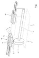
Figur 2- eine perspektivische schematische Darstellung eines weiteren Pneumatikzylinders als Linearantrieb, welcher mit einer Einrichtung zur Ermittlung beider Endlagenpositionen eines integrierten Antriebsgliedes ausgestattet ist.
- Figure 1
- a perspective, schematic representation of a pneumatic cylinder as a linear drive, which is equipped with a device for determining the current position of the internal piston, and
- Figure 2
- a perspective schematic representation of another pneumatic cylinder as a linear drive, which is equipped with a device for determining both end positions of an integrated drive member.
Gemäß Figur 1 besteht der hier als Pneumatikzylinder 1 ausgebildete Linearantrieb im Wesentlichen aus einem Antriebsgehäuse 2, in welchem ein Antriebsglied 3 in Form eines Kolbens längs bewegbar untergebracht ist. Vom Antriebsglied 3 aus verläuft eine Antriebsstange 4, hier eine Kolbenstange, welche das Antriebsgehäuse 2 zu einer Seite hin abgedichtet durchdringt, um die mit dem Pneumatikzylinder 1 erzeugte mechanische Kraft nach außen hin weiterzugeben. Die Krafterzeugung erfolgt in herkömmlicher Weise über - nicht weiter dargestellte - äußere Druckmittelanschlüsse, mit welchen das innenliegende Antriebsglied 3 wechselseitig beaufschlagbar ist, um ein Ein- oder Ausfahren der Antriebsstange 4 zu bewirken. Die Länge des Pneumatikzylinders 1 definiert den maximal möglichen Hub der Antriebsstange 4.According to FIG. 1, the linear drive designed here as a pneumatic cylinder 1 essentially consists of a
Des weiteren sind die Mittel zur Detektion der aktuellen Stellung des Antriebsgliedes 3 vorgesehen, welche über den gesamten Hubbereich des Pneumatikzylinders 1 verlaufen und im Wesentlichen aus einem Potentiometerfolienelement 5 bestehen. Das Potentiometerfolienelement 5 wird von einem im Antriebsglied 3 integrierten Permanentmagneten 6 magnetisch betätigt, indem eine Kontaktelektrode 7 des Potentiometerfolienelements 6 achsparallel zur Bewegungsrichtung des Antriebsglieds 3 verläuft und auf eine unterhalb angeordnete Widerstandsbahn 8 niedergedrückt wird, sobald das nach radial außen gerichtete magnetische Feld des Permanentmagneten 6 eine entsprechend örtlich konzentrierte Zugkraft aufbringt. Wenn sich der Permanentmagnet 6 nicht im Wirkungsbereich des Potentiometerfolienelements 5 befindet, dann bleibt die Kontaktelektrode 7 von der Widerstandsbahn 8 beabstandet. Hierfür dient ein zwischengeordneter Isolierrahmen 9.Furthermore, the means for detecting the current position of the
Für weitere Einzelheiten hinsichtlich des Potentiometerfolienelements 5 wird an dieser Stelle voll inhaltlich auf die DE 43 35 004 C2 verwiesen, welche Aufbau und Funktion eines Potentiometerfolienelements der Gattung nach näher beschreibt.For further details regarding the
Zur Verstärkung der magnetischen Kraft, welche die Kontaktelektrode 7 des Potentiometerfolienelements 5 betätigt, ist an der dem Permanentmagneten 6 des Antriebsgliedes 3 gegenüberliegenden Seite des Potentiometerfolienelements 5 ein Verstärkungselement 10 vorgesehen. Das Verstärkungselement 10 ist hier als eine auf einer oberen Betätigungsoberfläche 11 aufgebrachte ferrohaltige Kunststofffolie ausgebildet.To amplify the magnetic force which actuates the
In der Figur 2 sind spezielle Mittel zur Detektion der beiden Endlagenpositionen vorgesehen, welche nur im Bereich beider Endlagen angeordnet sind und im Wesentlichen aus je einem Potentiometerfolienelement 5a, 5b bestehen. Die Potentiometerfolienelemente 5a und 5b werden auch hier von einem im Antriebsglied 3 integrierten Permanentmagneten 6 magnetisch betätigt. Ansonsten gleicht diese Ausführungsform der vorstehend beschriebenen Ausführungsform.In FIG. 2, special means for detecting the two end position positions are provided, which are arranged only in the area of both end positions and essentially consist of a
Die Erfindung ist nicht beschränkt auf die vorstehend beschriebenen bevorzugten Ausführungsformen. Es sind vielmehr auch eine Reihe von Varianten hiervon denkbar, die vom Schutzbereich der Ansprüche umfasst sind. So ist die Anwendung der erfindungsgemäßen Einrichtung nicht allein beschränkt auf Pneumatikzylinder. Es können hiermit vielmehr auch andere als Linear- oder Drehantriebe ausgebildete Aktoren ausgestattet werden.The invention is not limited to the preferred embodiments described above. Rather, a number of variants thereof are also conceivable, which are within the scope of the claims. Thus, the use of the device according to the invention is not limited to pneumatic cylinders alone. It can rather, other actuators designed as linear or rotary drives can also be equipped with this.
- 11
- Pneumatikzylinderpneumatic cylinder
- 22
- Antriebsgehäusedrive housing
- 33
- Antriebsglieddrive member
- 44
- Antriebsstangedrive rod
- 55
- PotentiometerfolienelementPotentiometerfolienelement
- 66
- Permanentmagnetpermanent magnet
- 77
- Kontaktelektrodecontact electrode
- 88th
- Widerstandsbahnresistance path
- 99
- Isolierrahmeninsulating frame
- 1010
- Verstärkungselementreinforcing element
- 1111
- Betätigungsoberflächeactuating surface
Claims (6)
dadurch gekennzeichnet, dass die Mittel zur Detektion der aktuellen Stellung ein im magnetischen Wirkbereich des Permanentmagneten (6) und entlang des Hubwegs bzw. Drehwinkels angeordnetes Potentiometerfolienelement (5) umfassen, dessen Kontaktelektrode (7) achsparallel zum Antriebsglied (3) verläuft und über die magnetische Kraft des Permanentmagneten (6) örtlich konzentriert betätigbar ist, wobei an der dem Permanentmagneten (6) des Antriebsgliedes (3) gegenüberliegenden Seite des Potentiometerfolienelements (5) mindestens ein Verstärkungselement (10) in Form eines auf der Betätigungsoberfläche (11) des Potentiometerfolienelements (5) aufgebrachte ferrohaltige Kunststofffolie angeordnet ist.Device for determining the current position of a drive element (3) along the stroke or angle of rotation, in particular in the case of a linear or rotary drive operated by pressure medium, which is movably accommodated within a drive housing (2) by the application of pressure medium, the drive element (3) being a permanent magnet (6 ) for magnetic interaction with means arranged outside or on the drive housing (2) for detecting the current position of a drive member (3),
characterized in that the means for detecting the current position comprise a potentiometer foil element (5) arranged in the magnetic effective range of the permanent magnet (6) and along the stroke path or angle of rotation, the contact electrode (7) of which runs axially parallel to the drive member (3) and via the magnetic one The force of the permanent magnet (6) can be actuated in a locally concentrated manner, at least one reinforcing element (10) in the form of a on the actuating surface (11) of the potentiometer film element (5) on the side of the potentiometer film element (5) opposite the permanent magnet (6) of the drive member (3) ) applied ferro-containing plastic film is arranged.
dadurch gekennzeichnet, dass die Mittel zu Detektion der aktuellen Stellung eines Antriebsgliedes (3) lediglich in mindestens einer Endlagenposition desselben angeordnet sind, um eine Art Endlagenschalter zu bilden.Device according to claim 1,
characterized in that the means for detecting the current position of a drive member (3) are arranged only in at least one end position thereof in order to form a type of end position switch.
dadurch gekennzeichnet, dass das Antriebsglied (3) ein Kolben eines Pneumatikzylinders (1) als Linearantrieb ist.Device according to claim 1 or 2,
characterized in that the drive member (3) is a piston of a pneumatic cylinder (1) as a linear drive.
dadurch gekennzeichnet, dass das Antriebsglied (3) ein Drehflügel eines pneumatischen Drehantriebs ist.Device according to claim 1 or 2,
characterized in that the drive member (3) is a rotary vane of a pneumatic rotary drive.
dadurch gekennzeichnet, dass der Linearantrieb bzw. der Drehantrieb genau zwei Endlagenpositionen aufweist, denen jeweils ein einziges Potentiometerfolienelement (5a, 5b) zugeordnet ist.Device according to claim 2,
characterized in that the linear drive or the rotary drive has exactly two end position positions, each of which is assigned a single potentiometer film element (5a, 5b).
dadurch gekennzeichnet, dass das Potentiometerfolienelement (5; 5a, 5b) innerhalb eines in die Wandung des Antriebsgehäuses (2) eingebrachten geschlossenen Kanals untergebracht ist.Device according to one of the preceding claims,
characterized in that the potentiometer film element (5; 5a, 5b) is accommodated within a closed channel introduced into the wall of the drive housing (2).
Applications Claiming Priority (4)
| Application Number | Priority Date | Filing Date | Title |
|---|---|---|---|
| DE10329044 | 2003-06-27 | ||
| DE2003129044 DE10329044B4 (en) | 2003-06-27 | 2003-06-27 | Means for determining the current position of a drive member along the stroke or angle of rotation, in particular in a fluid-operated linear or rotary drive |
| DE2003129045 DE10329045B4 (en) | 2003-06-27 | 2003-06-27 | Means for determining at least one end position of a drive member, in particular a fluid-operated linear or rotary drive |
| DE10329045 | 2003-06-27 |
Publications (2)
| Publication Number | Publication Date |
|---|---|
| EP1491771A1 true EP1491771A1 (en) | 2004-12-29 |
| EP1491771B1 EP1491771B1 (en) | 2006-03-01 |
Family
ID=33420024
Family Applications (1)
| Application Number | Title | Priority Date | Filing Date |
|---|---|---|---|
| EP04103012A Not-in-force EP1491771B1 (en) | 2003-06-27 | 2004-06-28 | Device for determining the actual position of an actuator |
Country Status (3)
| Country | Link |
|---|---|
| EP (1) | EP1491771B1 (en) |
| AT (1) | ATE319015T1 (en) |
| DE (1) | DE502004000325D1 (en) |
Cited By (5)
| Publication number | Priority date | Publication date | Assignee | Title |
|---|---|---|---|---|
| WO2008058751A2 (en) * | 2006-11-18 | 2008-05-22 | Hirschmann Automotive Gmbh | Magnetic position sensor |
| EP2071276A1 (en) * | 2007-11-23 | 2009-06-17 | Metallux AG | Sensor |
| EP2230486A2 (en) | 2009-03-19 | 2010-09-22 | Metallux AG | Position sensor |
| DE102009020286A1 (en) | 2009-05-07 | 2010-11-11 | Robert Bosch Gmbh | Pressurizing medium cylinder i.e. pneumatic cylinder, for use in automation engineering field, has magnet elements coordinated to operating parameters of sensors and allocated to sensors by anti-twist protection unit of piston |
| DE102016213514A1 (en) * | 2016-07-22 | 2018-01-25 | Continental Automotive Gmbh | Passive magnetic position sensor |
Families Citing this family (2)
| Publication number | Priority date | Publication date | Assignee | Title |
|---|---|---|---|---|
| DE202008013690U1 (en) | 2007-11-26 | 2009-02-12 | Metallux Ag | sensor |
| DE102009025458B4 (en) | 2009-06-19 | 2016-09-01 | Metallux Ag | sensor |
Citations (4)
| Publication number | Priority date | Publication date | Assignee | Title |
|---|---|---|---|---|
| US3736396A (en) * | 1970-08-06 | 1973-05-29 | H Siegel | Minimum friction contactors |
| DE3803268A1 (en) * | 1988-02-04 | 1989-04-13 | Bosch Gmbh Robert | Measuring device for a working cylinder |
| DE4335004A1 (en) * | 1993-10-14 | 1995-04-20 | Hoffmann & Krippner Gmbh | Sensor |
| US5442865A (en) * | 1993-03-24 | 1995-08-22 | Vdo Adolf Schindling Ag | Passive magnetic position sensor |
-
2004
- 2004-06-28 DE DE502004000325T patent/DE502004000325D1/en active Active
- 2004-06-28 EP EP04103012A patent/EP1491771B1/en not_active Not-in-force
- 2004-06-28 AT AT04103012T patent/ATE319015T1/en not_active IP Right Cessation
Patent Citations (4)
| Publication number | Priority date | Publication date | Assignee | Title |
|---|---|---|---|---|
| US3736396A (en) * | 1970-08-06 | 1973-05-29 | H Siegel | Minimum friction contactors |
| DE3803268A1 (en) * | 1988-02-04 | 1989-04-13 | Bosch Gmbh Robert | Measuring device for a working cylinder |
| US5442865A (en) * | 1993-03-24 | 1995-08-22 | Vdo Adolf Schindling Ag | Passive magnetic position sensor |
| DE4335004A1 (en) * | 1993-10-14 | 1995-04-20 | Hoffmann & Krippner Gmbh | Sensor |
Cited By (11)
| Publication number | Priority date | Publication date | Assignee | Title |
|---|---|---|---|---|
| WO2008058751A2 (en) * | 2006-11-18 | 2008-05-22 | Hirschmann Automotive Gmbh | Magnetic position sensor |
| WO2008058751A3 (en) * | 2006-11-18 | 2009-01-29 | Hirschmann Automotive Gmbh | Magnetic position sensor |
| JP2010510480A (en) * | 2006-11-18 | 2010-04-02 | ヒルシュマン オートモーティヴ ゲゼルシャフト ミット ベシュレンクテル ハフツング | Magnetic position sensor |
| US8330450B2 (en) | 2006-11-18 | 2012-12-11 | Hirschmann Automotive Gmbh | Magnetic position sensor |
| EP2071276A1 (en) * | 2007-11-23 | 2009-06-17 | Metallux AG | Sensor |
| EP2230486A2 (en) | 2009-03-19 | 2010-09-22 | Metallux AG | Position sensor |
| DE102009013533A1 (en) | 2009-03-19 | 2010-09-23 | Metallux Ag | position sensor |
| EP2230486A3 (en) * | 2009-03-19 | 2012-08-01 | Metallux AG | Position sensor |
| DE102009020286A1 (en) | 2009-05-07 | 2010-11-11 | Robert Bosch Gmbh | Pressurizing medium cylinder i.e. pneumatic cylinder, for use in automation engineering field, has magnet elements coordinated to operating parameters of sensors and allocated to sensors by anti-twist protection unit of piston |
| DE102016213514A1 (en) * | 2016-07-22 | 2018-01-25 | Continental Automotive Gmbh | Passive magnetic position sensor |
| US11022478B2 (en) | 2016-07-22 | 2021-06-01 | Vitesco Technologies GmbH | Passive magnetic position sensor |
Also Published As
| Publication number | Publication date |
|---|---|
| ATE319015T1 (en) | 2006-03-15 |
| EP1491771B1 (en) | 2006-03-01 |
| DE502004000325D1 (en) | 2006-04-27 |
Similar Documents
| Publication | Publication Date | Title |
|---|---|---|
| EP0427102B1 (en) | Flow meter for measuring the flow rate in a conduit | |
| EP1250534B1 (en) | Control-valve drive with sensor unit for detecting the position of the valve | |
| EP1914459A1 (en) | Valve assembly with positioning sensor | |
| DE102005029494B4 (en) | Piston-cylinder arrangement | |
| EP2507592B1 (en) | Hand-operated throttle with rotational angle measuring system | |
| EP3619445B1 (en) | Method for operating an actuator arrangement for a clutch operating system, and actuator arrangement | |
| EP1491771B1 (en) | Device for determining the actual position of an actuator | |
| WO1996033547A1 (en) | Drive device with an electric motor and a relay switching the motor current | |
| WO2014063695A2 (en) | Sensor system and piston cylinder arrangment, in particular for use in a clutch actuation system in a motor vehicle | |
| DE2553454B2 (en) | Permanent magnetic display device, primarily for flow meters | |
| DE102005005011A1 (en) | Hydraulic cylinder for actuation of cabriolet canopy top, has actuator position detecting mechanism with magnets working together, such that sliding collector of potentiometer follows piston that is connected to actuator | |
| DE10329044B4 (en) | Means for determining the current position of a drive member along the stroke or angle of rotation, in particular in a fluid-operated linear or rotary drive | |
| DE10152178C2 (en) | Pressure cylinder with a displaceable sensor for the detection of the piston position | |
| EP0268030B1 (en) | Potentiometer or adjustable resistorce | |
| DE4214284A1 (en) | ELECTROMAGNETIC LINEAR MOTOR | |
| DE102004004100A1 (en) | Position sensor and corresponding method for detecting the position of a rotating body | |
| DE10329045A1 (en) | Drive member position determining device for use with a pneumatically or hydraulically operated drive has a potentiometer film and contact electrode arranged parallel to the drive member on which a permanent magnet is mounted | |
| DE3240351A1 (en) | PRESSURE-OPERATED WORK CYLINDER | |
| EP2878831A1 (en) | Working cylinder | |
| DE3939978A1 (en) | Membrane position monitor for brake servo - has telescopic sensor coaxial in vacuum connection valve | |
| DE102016207982B4 (en) | locking device | |
| EP0559634A1 (en) | Position sensor | |
| DE19846418A1 (en) | Hydraulic valve has sensor with sensing element in contact with peripheral valve piston contact area generating electrical or electronic signal depending on piston position changes | |
| DE19846182B4 (en) | Exhaust gas recirculation valve, comprising a circuit arrangement for detecting the switching state of at least one pneumatic switching means | |
| DE10324163B4 (en) | Self-sufficient cylinder valve unit |
Legal Events
| Date | Code | Title | Description |
|---|---|---|---|
| PUAI | Public reference made under article 153(3) epc to a published international application that has entered the european phase |
Free format text: ORIGINAL CODE: 0009012 |
|
| AK | Designated contracting states |
Kind code of ref document: A1 Designated state(s): AT BE BG CH CY CZ DE DK EE ES FI FR GB GR HU IE IT LI LU MC NL PL PT RO SE SI SK TR |
|
| AX | Request for extension of the european patent |
Extension state: AL HR LT LV MK |
|
| 17P | Request for examination filed |
Effective date: 20041201 |
|
| GRAP | Despatch of communication of intention to grant a patent |
Free format text: ORIGINAL CODE: EPIDOSNIGR1 |
|
| AKX | Designation fees paid |
Designated state(s): AT BE BG CH CY CZ DE DK EE ES FI FR GB GR HU IE IT LI LU MC NL PL PT RO SE SI SK TR |
|
| GRAS | Grant fee paid |
Free format text: ORIGINAL CODE: EPIDOSNIGR3 |
|
| GRAA | (expected) grant |
Free format text: ORIGINAL CODE: 0009210 |
|
| AK | Designated contracting states |
Kind code of ref document: B1 Designated state(s): AT BE BG CH CY CZ DE DK EE ES FI FR GB GR HU IE IT LI LU MC NL PL PT RO SE SI SK TR |
|
| PG25 | Lapsed in a contracting state [announced via postgrant information from national office to epo] |
Ref country code: IE Free format text: LAPSE BECAUSE OF FAILURE TO SUBMIT A TRANSLATION OF THE DESCRIPTION OR TO PAY THE FEE WITHIN THE PRESCRIBED TIME-LIMIT Effective date: 20060301 Ref country code: SI Free format text: LAPSE BECAUSE OF FAILURE TO SUBMIT A TRANSLATION OF THE DESCRIPTION OR TO PAY THE FEE WITHIN THE PRESCRIBED TIME-LIMIT Effective date: 20060301 Ref country code: SK Free format text: LAPSE BECAUSE OF FAILURE TO SUBMIT A TRANSLATION OF THE DESCRIPTION OR TO PAY THE FEE WITHIN THE PRESCRIBED TIME-LIMIT Effective date: 20060301 Ref country code: RO Free format text: LAPSE BECAUSE OF FAILURE TO SUBMIT A TRANSLATION OF THE DESCRIPTION OR TO PAY THE FEE WITHIN THE PRESCRIBED TIME-LIMIT Effective date: 20060301 Ref country code: NL Free format text: LAPSE BECAUSE OF FAILURE TO SUBMIT A TRANSLATION OF THE DESCRIPTION OR TO PAY THE FEE WITHIN THE PRESCRIBED TIME-LIMIT Effective date: 20060301 Ref country code: PL Free format text: LAPSE BECAUSE OF FAILURE TO SUBMIT A TRANSLATION OF THE DESCRIPTION OR TO PAY THE FEE WITHIN THE PRESCRIBED TIME-LIMIT Effective date: 20060301 Ref country code: FI Free format text: LAPSE BECAUSE OF FAILURE TO SUBMIT A TRANSLATION OF THE DESCRIPTION OR TO PAY THE FEE WITHIN THE PRESCRIBED TIME-LIMIT Effective date: 20060301 |
|
| REG | Reference to a national code |
Ref country code: GB Ref legal event code: FG4D Free format text: NOT ENGLISH |
|
| REG | Reference to a national code |
Ref country code: CH Ref legal event code: EP |
|
| REG | Reference to a national code |
Ref country code: IE Ref legal event code: FG4D Free format text: LANGUAGE OF EP DOCUMENT: GERMAN |
|
| REF | Corresponds to: |
Ref document number: 502004000325 Country of ref document: DE Date of ref document: 20060427 Kind code of ref document: P |
|
| PG25 | Lapsed in a contracting state [announced via postgrant information from national office to epo] |
Ref country code: DK Free format text: LAPSE BECAUSE OF FAILURE TO SUBMIT A TRANSLATION OF THE DESCRIPTION OR TO PAY THE FEE WITHIN THE PRESCRIBED TIME-LIMIT Effective date: 20060601 Ref country code: BG Free format text: LAPSE BECAUSE OF FAILURE TO SUBMIT A TRANSLATION OF THE DESCRIPTION OR TO PAY THE FEE WITHIN THE PRESCRIBED TIME-LIMIT Effective date: 20060601 |
|
| REG | Reference to a national code |
Ref country code: SE Ref legal event code: TRGR |
|
| PG25 | Lapsed in a contracting state [announced via postgrant information from national office to epo] |
Ref country code: ES Free format text: LAPSE BECAUSE OF FAILURE TO SUBMIT A TRANSLATION OF THE DESCRIPTION OR TO PAY THE FEE WITHIN THE PRESCRIBED TIME-LIMIT Effective date: 20060612 |
|
| GBT | Gb: translation of ep patent filed (gb section 77(6)(a)/1977) |
Effective date: 20060519 |
|
| PG25 | Lapsed in a contracting state [announced via postgrant information from national office to epo] |
Ref country code: MC Free format text: LAPSE BECAUSE OF NON-PAYMENT OF DUE FEES Effective date: 20060630 Ref country code: BE Free format text: LAPSE BECAUSE OF NON-PAYMENT OF DUE FEES Effective date: 20060630 |
|
| PG25 | Lapsed in a contracting state [announced via postgrant information from national office to epo] |
Ref country code: PT Free format text: LAPSE BECAUSE OF FAILURE TO SUBMIT A TRANSLATION OF THE DESCRIPTION OR TO PAY THE FEE WITHIN THE PRESCRIBED TIME-LIMIT Effective date: 20060801 |
|
| NLV1 | Nl: lapsed or annulled due to failure to fulfill the requirements of art. 29p and 29m of the patents act | ||
| REG | Reference to a national code |
Ref country code: IE Ref legal event code: FD4D |
|
| ET | Fr: translation filed | ||
| PLBE | No opposition filed within time limit |
Free format text: ORIGINAL CODE: 0009261 |
|
| STAA | Information on the status of an ep patent application or granted ep patent |
Free format text: STATUS: NO OPPOSITION FILED WITHIN TIME LIMIT |
|
| 26N | No opposition filed |
Effective date: 20061204 |
|
| PG25 | Lapsed in a contracting state [announced via postgrant information from national office to epo] |
Ref country code: AT Free format text: LAPSE BECAUSE OF NON-PAYMENT OF DUE FEES Effective date: 20060628 |
|
| BERE | Be: lapsed |
Owner name: REXROTH MECMAN G.M.B.H. Effective date: 20060630 |
|
| PG25 | Lapsed in a contracting state [announced via postgrant information from national office to epo] |
Ref country code: CZ Free format text: LAPSE BECAUSE OF FAILURE TO SUBMIT A TRANSLATION OF THE DESCRIPTION OR TO PAY THE FEE WITHIN THE PRESCRIBED TIME-LIMIT Effective date: 20060301 Ref country code: GR Free format text: LAPSE BECAUSE OF FAILURE TO SUBMIT A TRANSLATION OF THE DESCRIPTION OR TO PAY THE FEE WITHIN THE PRESCRIBED TIME-LIMIT Effective date: 20060602 |
|
| PG25 | Lapsed in a contracting state [announced via postgrant information from national office to epo] |
Ref country code: EE Free format text: LAPSE BECAUSE OF FAILURE TO SUBMIT A TRANSLATION OF THE DESCRIPTION OR TO PAY THE FEE WITHIN THE PRESCRIBED TIME-LIMIT Effective date: 20060301 |
|
| PG25 | Lapsed in a contracting state [announced via postgrant information from national office to epo] |
Ref country code: TR Free format text: LAPSE BECAUSE OF FAILURE TO SUBMIT A TRANSLATION OF THE DESCRIPTION OR TO PAY THE FEE WITHIN THE PRESCRIBED TIME-LIMIT Effective date: 20060301 Ref country code: LU Free format text: LAPSE BECAUSE OF NON-PAYMENT OF DUE FEES Effective date: 20060628 Ref country code: HU Free format text: LAPSE BECAUSE OF FAILURE TO SUBMIT A TRANSLATION OF THE DESCRIPTION OR TO PAY THE FEE WITHIN THE PRESCRIBED TIME-LIMIT Effective date: 20060902 |
|
| PG25 | Lapsed in a contracting state [announced via postgrant information from national office to epo] |
Ref country code: CY Free format text: LAPSE BECAUSE OF FAILURE TO SUBMIT A TRANSLATION OF THE DESCRIPTION OR TO PAY THE FEE WITHIN THE PRESCRIBED TIME-LIMIT Effective date: 20060301 |
|
| REG | Reference to a national code |
Ref country code: CH Ref legal event code: PL |
|
| PG25 | Lapsed in a contracting state [announced via postgrant information from national office to epo] |
Ref country code: CH Free format text: LAPSE BECAUSE OF NON-PAYMENT OF DUE FEES Effective date: 20080630 Ref country code: LI Free format text: LAPSE BECAUSE OF NON-PAYMENT OF DUE FEES Effective date: 20080630 |
|
| PGFP | Annual fee paid to national office [announced via postgrant information from national office to epo] |
Ref country code: SE Payment date: 20091222 Year of fee payment: 7 |
|
| PGFP | Annual fee paid to national office [announced via postgrant information from national office to epo] |
Ref country code: FR Payment date: 20100706 Year of fee payment: 7 |
|
| PGFP | Annual fee paid to national office [announced via postgrant information from national office to epo] |
Ref country code: IT Payment date: 20100626 Year of fee payment: 7 |
|
| PGFP | Annual fee paid to national office [announced via postgrant information from national office to epo] |
Ref country code: DE Payment date: 20100824 Year of fee payment: 7 Ref country code: GB Payment date: 20100401 Year of fee payment: 7 |
|
| REG | Reference to a national code |
Ref country code: SE Ref legal event code: EUG |
|
| GBPC | Gb: european patent ceased through non-payment of renewal fee |
Effective date: 20110628 |
|
| PG25 | Lapsed in a contracting state [announced via postgrant information from national office to epo] |
Ref country code: IT Free format text: LAPSE BECAUSE OF NON-PAYMENT OF DUE FEES Effective date: 20110628 |
|
| REG | Reference to a national code |
Ref country code: FR Ref legal event code: ST Effective date: 20120229 |
|
| REG | Reference to a national code |
Ref country code: DE Ref legal event code: R119 Ref document number: 502004000325 Country of ref document: DE Effective date: 20120103 |
|
| PG25 | Lapsed in a contracting state [announced via postgrant information from national office to epo] |
Ref country code: FR Free format text: LAPSE BECAUSE OF NON-PAYMENT OF DUE FEES Effective date: 20110630 Ref country code: DE Free format text: LAPSE BECAUSE OF NON-PAYMENT OF DUE FEES Effective date: 20120103 |
|
| PG25 | Lapsed in a contracting state [announced via postgrant information from national office to epo] |
Ref country code: GB Free format text: LAPSE BECAUSE OF NON-PAYMENT OF DUE FEES Effective date: 20110628 |
|
| PG25 | Lapsed in a contracting state [announced via postgrant information from national office to epo] |
Ref country code: SE Free format text: LAPSE BECAUSE OF NON-PAYMENT OF DUE FEES Effective date: 20110629 |