EP1491732A1 - Method and device for controlling the speed of the valves of an internal combustion engine - Google Patents
Method and device for controlling the speed of the valves of an internal combustion engine Download PDFInfo
- Publication number
- EP1491732A1 EP1491732A1 EP20040102852 EP04102852A EP1491732A1 EP 1491732 A1 EP1491732 A1 EP 1491732A1 EP 20040102852 EP20040102852 EP 20040102852 EP 04102852 A EP04102852 A EP 04102852A EP 1491732 A1 EP1491732 A1 EP 1491732A1
- Authority
- EP
- European Patent Office
- Prior art keywords
- valve
- hydraulic actuator
- speed
- closure
- impact
- Prior art date
- Legal status (The legal status is an assumption and is not a legal conclusion. Google has not performed a legal analysis and makes no representation as to the accuracy of the status listed.)
- Granted
Links
Images


Classifications
-
- F—MECHANICAL ENGINEERING; LIGHTING; HEATING; WEAPONS; BLASTING
- F02—COMBUSTION ENGINES; HOT-GAS OR COMBUSTION-PRODUCT ENGINE PLANTS
- F02D—CONTROLLING COMBUSTION ENGINES
- F02D35/00—Controlling engines, dependent on conditions exterior or interior to engines, not otherwise provided for
-
- F—MECHANICAL ENGINEERING; LIGHTING; HEATING; WEAPONS; BLASTING
- F01—MACHINES OR ENGINES IN GENERAL; ENGINE PLANTS IN GENERAL; STEAM ENGINES
- F01L—CYCLICALLY OPERATING VALVES FOR MACHINES OR ENGINES
- F01L9/00—Valve-gear or valve arrangements actuated non-mechanically
- F01L9/10—Valve-gear or valve arrangements actuated non-mechanically by fluid means, e.g. hydraulic
-
- F—MECHANICAL ENGINEERING; LIGHTING; HEATING; WEAPONS; BLASTING
- F02—COMBUSTION ENGINES; HOT-GAS OR COMBUSTION-PRODUCT ENGINE PLANTS
- F02D—CONTROLLING COMBUSTION ENGINES
- F02D13/00—Controlling the engine output power by varying inlet or exhaust valve operating characteristics, e.g. timing
- F02D13/02—Controlling the engine output power by varying inlet or exhaust valve operating characteristics, e.g. timing during engine operation
- F02D13/0253—Fully variable control of valve lift and timing using camless actuation systems such as hydraulic, pneumatic or electromagnetic actuators, e.g. solenoid valves
-
- F—MECHANICAL ENGINEERING; LIGHTING; HEATING; WEAPONS; BLASTING
- F02—COMBUSTION ENGINES; HOT-GAS OR COMBUSTION-PRODUCT ENGINE PLANTS
- F02D—CONTROLLING COMBUSTION ENGINES
- F02D41/00—Electrical control of supply of combustible mixture or its constituents
- F02D41/20—Output circuits, e.g. for controlling currents in command coils
-
- F—MECHANICAL ENGINEERING; LIGHTING; HEATING; WEAPONS; BLASTING
- F01—MACHINES OR ENGINES IN GENERAL; ENGINE PLANTS IN GENERAL; STEAM ENGINES
- F01L—CYCLICALLY OPERATING VALVES FOR MACHINES OR ENGINES
- F01L2800/00—Methods of operation using a variable valve timing mechanism
-
- F—MECHANICAL ENGINEERING; LIGHTING; HEATING; WEAPONS; BLASTING
- F02—COMBUSTION ENGINES; HOT-GAS OR COMBUSTION-PRODUCT ENGINE PLANTS
- F02D—CONTROLLING COMBUSTION ENGINES
- F02D41/00—Electrical control of supply of combustible mixture or its constituents
- F02D41/0002—Controlling intake air
- F02D2041/001—Controlling intake air for engines with variable valve actuation
-
- F—MECHANICAL ENGINEERING; LIGHTING; HEATING; WEAPONS; BLASTING
- F02—COMBUSTION ENGINES; HOT-GAS OR COMBUSTION-PRODUCT ENGINE PLANTS
- F02D—CONTROLLING COMBUSTION ENGINES
- F02D2200/00—Input parameters for engine control
- F02D2200/02—Input parameters for engine control the parameters being related to the engine
- F02D2200/025—Engine noise, e.g. determined by using an acoustic sensor
-
- Y—GENERAL TAGGING OF NEW TECHNOLOGICAL DEVELOPMENTS; GENERAL TAGGING OF CROSS-SECTIONAL TECHNOLOGIES SPANNING OVER SEVERAL SECTIONS OF THE IPC; TECHNICAL SUBJECTS COVERED BY FORMER USPC CROSS-REFERENCE ART COLLECTIONS [XRACs] AND DIGESTS
- Y02—TECHNOLOGIES OR APPLICATIONS FOR MITIGATION OR ADAPTATION AGAINST CLIMATE CHANGE
- Y02T—CLIMATE CHANGE MITIGATION TECHNOLOGIES RELATED TO TRANSPORTATION
- Y02T10/00—Road transport of goods or passengers
- Y02T10/10—Internal combustion engine [ICE] based vehicles
- Y02T10/12—Improving ICE efficiencies
Definitions
- the present invention relates to a method of controlling the speed of the valves of an internal combustion engine.
- valves of an internal combustion engine are moved mechanically by means of a camshaft.
- alternative systems are currently being tried out.
- This applicants are in particular experimenting with an electro-hydraulic actuation unit for the valves of an internal combustion engine of the type disclosed in European Patent 1 233 152 in the name of the applicants.
- This electro-hydraulic unit is driven by an electronic unit and makes it possible very accurately to vary the instants of opening and closure of each valve in accordance with a cycle assigned as a function of the angular speed of the crankshaft and other operating parameters of the engine, thereby substantially improving engine performance.
- the electro-hydraulic unit currently being tested comprises, for each intake and/or exhaust valve of the engine, an electro-hydraulic actuation device which comprises a hydraulic actuator adapted axially to move the valve from the closed position to the position of maximum opening, overcoming the action of an elastic member adapted to maintain this valve in the closed position, and a hydraulic distributor valve adapted to regulate the flow of pressurised oil to and from this hydraulic actuator so as to control the displacement of the valve between the closed position and the position of maximum opening.
- an electro-hydraulic actuation device which comprises a hydraulic actuator adapted axially to move the valve from the closed position to the position of maximum opening, overcoming the action of an elastic member adapted to maintain this valve in the closed position, and a hydraulic distributor valve adapted to regulate the flow of pressurised oil to and from this hydraulic actuator so as to control the displacement of the valve between the closed position and the position of maximum opening.
- the electro-hydraulic unit being tested is provided with a hydraulic circuit comprising an oil collection tank, within which the oil to be supplied to the actuators is stored, and a pump unit adapted to supply pressurised oil to the various distributors by taking it directly from the collection tank.
- the electro-hydraulic unit disclosed in European Patent Application 1 233 152 comprises a slide distributor valve which is able to assume a first operating position in which it brings the linear hydraulic actuator into direct communication with the a collection tank for the fluid at ambient pressure, a second operating position, in which it isolates the linear hydraulic actuator so as to prevent the flow of fluid to and from this actuator and a third operating position in which it brings the linear hydraulic actuator into direct communication with a branch containing the pressurised fluid.
- the unit as disclosed has the substantial advantage that its structure is particularly simple, which ensures a high degree of reliability over time, thus enabling its use in the automobile engineering sector.
- the object of the present invention is to provide a method of controlling the speed of the valves of an internal combustion engine able to limit the above-described drawback.
- the present invention relates to a method of controlling of the speed of impact of the valves in an electro-hydraulic actuation unit for the valves of an internal combustion engine, the electro-hydraulic unit comprising a hydraulic actuator adapted to open a respective valve with a pressurised fluid, a spring opposing the hydraulic actuator in order to close the valve and to discharge the fluid from the hydraulic actuator to a collection tank, the method being characterised in that the pressure of the fluid is controlled in the hydraulic actuator, during the final phase of closure of the valve.
- the present invention relates a device for controlling the speed of the valves of an internal combustion engine.
- the present invention relates to a device for controlling of the speed of impact of the valves in an electro-hydraulic actuation unit for the valves of an internal combustion engine, the electro-hydraulic unit comprising a hydraulic actuator adapted to open a respective valve with a pressurised fluid, a spring opposing the hydraulic actuator in order to close the valve and to discharge the fluid from the hydraulic actuator to a collection tank, the device being characterised in that it comprises control means for controlling the pressure of the fluid in the hydraulic actuator, during the final phase of closure of the valve.
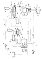
- an electro-hydraulic unit for the actuation of the valves 2 of an internal combustion engine M is shown overall by 1. Only one valve 2, coupled to a respective seat 2A, is shown in Fig. 1, although it will be appreciated that the electro-hydraulic unit 1 is adapted to drive all the intake and exhaust valves of the engine M.
- the opening of the valve 2 is defined as the phase of transition of the valve 2 from the closed position to the position of maximum opening; the closure of the valve 2 is defined as the phase of transition of the valve 2 from the position of maximum opening to the closed position; and maintenance is defined as the phase during the which the valve 2 remains in the position of maximum opening.
- the terms opening, closing and maintaining the valve 2 consequently have the same meaning.
- the unit 1 comprises a hydraulic circuit 3 and a control device 4.
- the hydraulic circuit 3 comprises a circuit 5 common to all the valves 2 and a plurality of actuation devices 6, each of which is associated with a respective valve 2.
- actuation devices 6 each of which is associated with a respective valve 2.
- Fig. 1 for reasons of simplicity, only one device 6 associated with its respective valve 2 is shown.
- the circuit 5 comprises an oil collection tank 7, a pump unit 8 and two branches 9 and 10 which are supplied with pressurised fluid and along which respective pressure regulators 11 and 12 and respective pressure accumulators 13 and 14 are disposed in sequence.
- the two branches 9 and 10 of the circuit 5, downstream of the respective accumulators 13 and 14, are connected to the actuation devices 6, each of which comprises a control selector 15, a slide distributor valve 16 and a hydraulic actuator 17 rigidly connected to the valve 2.
- the selector 15 is connected to the branch 10, the tank 7 and a branch 18 which connects the selector 15 to the slide valve 16 in order to drive this slide valve 16.
- the slide valve 16 is connected to the branch 9, the tank 7 and a supply branch 19 to the actuator 17 and an exhaust branch 20 from the actuator 17.
- the branch 19 and the branch 20 are connected by an exhaust branch 21, along which an orifice 22 is disposed.
- the function of the exhaust branch 21 and the orifice 22 is to slow down the valve 2 during the closing phase and to keep the speed of closure of the valve 2 constant. The slowing down of the valve 2 takes place in particular during the final part of the closing stroke of the valve 2, as will be described below.
- the selector 15 is a three-way valve controlled by an electromagnet 23 and a spring 24 and is adapted to assume two positions: the spring 24, when the electromagnet 23 is not excited, maintains the selector in the first position, in which the branch 10 is closed off, while the branch 18 is connected to the tank 7 (Fig. 1); the electromagnet 23, when excited, overcomes the force of the spring 24 and disposes the selector 15 in the second position in which the branch 10 is connected to the branch 18.
- the slide distributor valve 16 is a four-way valve driven by a piston 25 and a spring 26 and is adapted substantially to assume four operating positions shown by P1, P2, P3 and P4 in Fig. 1. Although the slide valve 16 has four operating positions P1, P2, P3 and P4, in practice it has only two stable positions, i.e. the end positions shown by P1 and P4 respectively in Fig. 1. The operating positions P2 and P3 are transit positions between the opposing operating positions P1 and P4.
- the branch 20 In the operating position P1, the branch 20 is connected to the tank 7, while the branch 9 and the branch 19 are disconnected; in the operating position P2, all the connections are discontinued; in the operating position P3, the branch 9 is connected to the branch 19, while the return branch 20 is closed off: for this reason, the operating position P3 is defined as the actuation position; the operating position P4 again shows the same characteristics as the operating position P2.
- the linear hydraulic actuator 17 comprises a cylinder 27, a piston 28 connected to the valve 2 and a spring 29 adapted to maintain the valve 2 in the closed position.
- the cylinder 27 has a head 27a and a jacket 27b, along which a lateral discharge opening 30 is disposed.
- the piston 28 comprises a top 28a and a lateral surface 28b which, in specific positions, closes off the opening 30 of the piston 28.
- the slide valve 16 comprises a bushing 31 and a slide 32 sliding in the bushing 31 along an axis 33.
- the branch 19, the branch 9 and the branch 20 communicate with respective series of radial holes 34, 35, and 36 provided in the bushing 31.
- the radial holes 34, 35 and 36 of each series are distributed about the axis 33, while the series of radial holes 34, 35 and 36 are distributed along the axis 33 with a spacing determined as a function of the geometrical characteristics of the slide 32, which comprises two surfaces 37 and 38 substantially flush with the bushing 31 and separated by a hollow portion 39.
- a geometrical relationship between the axial extension of the surfaces 37 and 38 and the hollow portion 39 and the axial position of the series of holes 34, 35 and 26 so as to define all the operating positions P1, P2, P3 and P4 of the slide 32.
- the dimensions of the slide 32 and the bushing 31 make it possible simultaneously to dispose the hollow portion 39 at the location of both series of holes 34 and 35 and the surface 38 at the location of the series of holes 36, so as to block the return branch 20 and supply the pressurised oil from the branch 9 to the branch 19.
- the position described corresponds to the operating position P3 of Fig. 1 and is not in practice a stable position of the slide 32: the passage section or opening that the oil can use to move from the branch 9 to the branch 19 is variable as a function of the position of the slide 32.
- the control device 4 comprises an electronic control unit 40 which, as a function of data detected from the engine M such as, for instance, the number of revolutions RPM and other operating parameters, determines the instant of opening and the instant of closure of each valve 2.
- the unit 40 therefore controls the electromagnet 23 in order to determine, in cascade, the actuation of the selector 15 of the slide distributor valve 16 and the linear actuator 17.
- the control device 4 further comprises a sensor 41 of the oil temperature T, a sensor 42 of the position of the slide distributor valve 16 and a sensor 43 of the speed of impact of the valve 2.
- the position sensor 42 comprises two permanent magnets 44 and 45 which are embedded in the slide 32 and are disposed at a distance from one another along the axis 33 equal to the difference between the strokes of the slide 32 needed respectively to open and close the connection between the branch 9 and the branch 19 during the displacement of the slide 32 from left to right in Fig. 7.
- the sensor 42 comprises a detector 46 disposed along the bushing 31: the geometry of the slide distributor valve 16 causes the connection between the branch 9 and the branch 19 to begin after the displacement of the slide 32 by a first extent and to be terminated after a displacement of the slide 32 by a second extent.
- the detector 46 detects the transit of the magnet 45 (first extent of displacement) which represents the opening of the passage section, and the transit of the magnet 44 which represents the closure of the passage section during a displacement from P1 to P4. For a return displacement from P4 to P1, the details are reversed.
- the detector 46 detects the opening and closing positions of the passage sections as a result of displacements of the slide 32 in both directions.
- the sensor 43 is formed by an accelerometer which detects the impact with which the valve 2 is returned to its respective seat 2A.
- the sensor 43 is a detonation sensor whose detected and filtered signal is correlated with each valve 2.
- the unit 40 as well as controlling the electromagnet 23, also controls the pressure regulators 11 and 12 and the passage section of the orifice 22 of variable section.
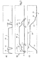
- section a) shows the curve A indicative of the displacement (ordinate) of the selector 15 as a function of time (abscissa);
- section b) shows the curve B indicative of the position (ordinate) of the slide distributor valve 16 and the curve C indicative of the passage section or opening (ordinate) connecting the branch 9 and the branch 19 as a function of time (abscissa);
- section c) shows the curve D indicative of the position (ordinate) of the valve 2 as a function of time (abscissa).
- the sections a), b) and c) are aligned such that the time scales are in phase with one another for all the sections a), b) and c). In this way, it is possible to compare the relations between the positions of the selector 15, the slide distributor valve 16, the effect of the position of the slide distributor valve 16 on the passage section and the position of the valve 2.
- the operating principle is based on the fact that the unit 40 excites the electromagnet 23 according to a cycle predetermined as a function of the engine point: i.e. operating parameters such as torque, number of revolutions or emissions.
- the valve 2 has a predetermined time t open needed to open the valve 2 and a predetermined time t close needed to close the valve 2, at least in part, which are substantially constant and are determined by the equivalent mass and rigidity of the system, where the system is understood as the assembly formed by the piston 28, the valve 2, the spring 29 and the oil contained in the cylinder 27.
- the times t open and t close are influenced by the characteristics of the oil and are obtained experimentally.
- the opening time of the passage section must correspond to t open during the opening phase of the valve and to the time t close during the closing phase of the valve 2.
- the operating position P3 of the slide distributor valve 16 is not a stable position and therefore, without detecting the position of the slide 32, it is impossible to detect the opening time of the passage section.
- the sensor 42 detects two points X1 and X2 of the curve B in order to determine the curve C of the passage section.
- the unit 40 detects the times t x1 and t x2 and calculates the time t spo , which is equal to the difference between t x2 and t x1 and represents the time elapsing between the detection of the two points X1 and X2: i.e.
- the time t spo corresponds to the opening time of the passage section during the opening phase of the valve 2 and may be defined as the actuation time of the actuator 17 during the opening phase of the valve 2.
- the unit 40 calculates the time t spc elapsing between the detection of the two points X2 and X1: the time t spc is equal to the difference between the times t x1 and t x2 and corresponds to the opening time of the passage section during the closing phase of the valve 2 which may be defined as the actuation time of the actuator 17 during the closing phase of the valve 2.
- the unit 40 calculates the respective differences between the values of t spo and t spc and the values t open and t close and emits respective error signals E o and E c when the differences calculated exceed respective threshold values H and K.
- the selector 15 operates according to a cycle in which the transition from the position shown in Fig. 1 to the connection position of the branches 10 and 18 determines the opening of the valve 2, the maintenance of the connection between the branches 10 and 18 determines the maintenance of the valve 2 in the open position and the discontinuation of the connection between the branches 10 and 18 determines the closure of the valve 2.
- the unit 40 displaces the selector 15 (portion A1 of curve A) in order to open the valve (portion B 1 of curve B of the slide distributor valve 16 and portion D1 of the curve D of the valve 2). Subsequently, in the presence of an error signal E o , the unit 40 moves the selector 15 (portion A2 of curve A) in order temporarily to discontinue the connection between the branches 10 and 18 in the lift phase after the detection of the point X1 and before the detection of the point X2 in order to delay the closure of the passage opening and synchronise the time t spo with the time t open .
- the slide distributor valve 16 oscillates (portion B2 of curve B) in the connection position between the branches 9 and 19.
- the discontinuation of the connection between the branches 10 and 18 determines the beginning of the closure of the valve 2 (portion D3 of curve D).
- the unit 40 In the presence of the error signal E c , the unit 40 temporarily connects the branch 10 to the branch 18 (portion A4 of curve A, Fig. 2a) during the closing phase of the valve 2 after the detection of the point X2 and before the detection of the point X1 in order to delay the closure of the connection between the branches 9 and 19.
- the slide distributor valve 16 oscillates in the closing phase in the connection position between the branches 9 and 19.
- the selector 15 is actuated after the detection of t x1 in order temporarily to disconnect the branches 10 and 18 and vary the connection time t spo during the opening phase.
- this temporary interruption may be carried out before the instant t x1 .
- the unit 40 calculates, at each cycle, the error signals E o and E c and possibly adjusts the times T spo and T spc of the successive cycle by adapting the displacement of the slide distributor valve 16 as a function of the times t open and t close .
- the spring 29 determines a pressure in the cylinder 27 greater than the pressure of the fluid in the branch 9. This situation means that, in the closing phase of the valve 2 when the branches 9 and 19 are connected to one another, part of the oil contained in the cylinder 27 flows back through the branch 19 to the branch 9.
- the branch 19 not only performs the function of a supply branch, but also the function of a return branch.
- the phase of expulsion of the oil from the actuator 17 via the branch 9 is completed in the predetermined time t close .
- This phase of expulsion of the oil via the branch 9 corresponds to the initial phase of closure of the valve 2. It will be appreciated as a result of the friction, the recovery is not complete and the valve 2 is not fully closed at the end of this initial phase.
- the slide distributor valve 16 reaches the operating position P1, in which the oil contained in the cylinder 27 is initially discharged via the opening 30 and the branch 20 (section D4 of curve D, Fig. 2c).
- the displacement of the piston 28 during the discharge of the oil to the tank 7 causes the progressive closure of the opening 30 and the residual oil in the cylinder 7 is therefore discharged via the discharge branch 21 and the orifice 22 (section D5 of curve D, Fig. 2b).
- the function of the orifice 22 is to slow down the descent of the valve 2 and to keep the speed of closure substantially constant.
- the unit 40 is able to vary the passage section of the orifice in order to regulate the closure speed.
- the discharge of the oil first via the branch 20 and then via the branches 20 and 21 corresponds to the final phase of closure of the valve 2.
- Fig. 3 shows, alongside the curve D relating to the displacement of the valve 2 and the curve A relating to the displacement of the selector 15, the curve F relating to the speed of the valve 2.
- the final section F1 of curve F comprises a substantially horizontal section indicating that the speed is constant (approximately 0.35 m/s) and a substantially vertical section indicating the impact (abrupt deceleration).
- the selector 15 is actuated for an instant during the approach phase of the valve 2 in order to modify the final section F2 of the curve F. This has the effect of slowing down the speed to some 0.05 m/s in order to reduce the impact.
- the actuation of the selector 15 and, in cascade, the slide distributor valve 16 makes it possible to control the pressure in the cylinder 27 during the final phase of discharge of the oil.
- the sensor 43 obtains a magnitude correlated with the speed of impact V 1 and the instant t c in which the valve 2 is closed on its respective seat 2A.
- the unit 40 obtains the value of the speed of impact V 1 and calculates the nominal speed of impact V N which is a function of the number of revolutions RPM of the engine M: for a low number of revolutions RPM, low speeds of impact V I are preferable, while for higher numbers of revolutions, higher speeds of impact V I are tolerable.
- the control unit 40 calculates the difference between the speed of impact V I and the nominal speed V N .
- the unit 40 calculates and emits an error signal E v in order to dispose the selector 15 instantaneously in the connection position between the branch 10 and the branch 18 during the final phase of closure of the valve 2 and to displace the slide distributor valve 16 from the operating position P1 to the operating position P2 and to discontinue the discharge of the cylinder 27.
- the time of supply of the pulse takes place an instant before the instant t c detected in the previous cycle.
- the detection of the instant t c is optional as, on the basis of the cycle assigned, it is possible to predict what the instant of closure of the valve 2 will be.
- the actuation of the selector 15 is prolonged.
- the actuation period is kept constant and the instant of actuation is varied.
- the regulation takes place by combining the two actions described above. The repetition of this control may also cause the slide distributor valve 16 to be brought into the position P3 and to supply pressurised oil into the actuator 17 in order to accentuate the deceleration of the valve 2 and further reduce the speed of impact V I .
- the function of the closed-cycle control is to check whether the speed of impact corresponds to a nominal speed V N . It is thus possible to check whether it is also necessary to increase the speed of impact V I of the previous cycle, for instance when moving from a low to a high number of revolutions of the engine M, in which case the device 4 does not increase the pressure in the cylinder 27.
- Both the temporary discontinuation of the discharge, and the temporary supply, of oil are part of the method for controlling the pressure during the final phase of discharge by means of the displacement of the slide distributor valve 16.
- the control consists in modulating the pressure increase in the cylinder 27 in order to decelerate the descent of the piston 28 and, thus, the closure of the valve 2.
- the pressure modulation it is also possible to omit the pressure increase in the cylinder 27.
- the first method uses the orifice 22 provided with a calibrated hole, and the second method is based on the control of the slide distributor valve 16.
- the first and the second method may be used jointly as described or separately.
- the closed-cycle control is particularly advantageous, although it will be appreciated that the pressure control in the cylinder 27 during the fmal discharge phase may also take place in open cycle.
Abstract
Description
- The present invention relates to a method of controlling the speed of the valves of an internal combustion engine.
- In general, the valves of an internal combustion engine are moved mechanically by means of a camshaft. Alongside this technology, long consolidated in the automobile engineering sector, alternative systems are currently being tried out. This applicants are in particular experimenting with an electro-hydraulic actuation unit for the valves of an internal combustion engine of the type disclosed in
European Patent 1 233 152 in the name of the applicants. This electro-hydraulic unit is driven by an electronic unit and makes it possible very accurately to vary the instants of opening and closure of each valve in accordance with a cycle assigned as a function of the angular speed of the crankshaft and other operating parameters of the engine, thereby substantially improving engine performance. - The electro-hydraulic unit currently being tested comprises, for each intake and/or exhaust valve of the engine, an electro-hydraulic actuation device which comprises a hydraulic actuator adapted axially to move the valve from the closed position to the position of maximum opening, overcoming the action of an elastic member adapted to maintain this valve in the closed position, and a hydraulic distributor valve adapted to regulate the flow of pressurised oil to and from this hydraulic actuator so as to control the displacement of the valve between the closed position and the position of maximum opening.
- In order to provide for the pressurised oil, the electro-hydraulic unit being tested is provided with a hydraulic circuit comprising an oil collection tank, within which the oil to be supplied to the actuators is stored, and a pump unit adapted to supply pressurised oil to the various distributors by taking it directly from the collection tank. The electro-hydraulic unit disclosed in
European Patent Application 1 233 152 comprises a slide distributor valve which is able to assume a first operating position in which it brings the linear hydraulic actuator into direct communication with the a collection tank for the fluid at ambient pressure, a second operating position, in which it isolates the linear hydraulic actuator so as to prevent the flow of fluid to and from this actuator and a third operating position in which it brings the linear hydraulic actuator into direct communication with a branch containing the pressurised fluid. - The unit as disclosed has the substantial advantage that its structure is particularly simple, which ensures a high degree of reliability over time, thus enabling its use in the automobile engineering sector.
- However, the tests under way have shown that each valve approaches its relative seat at too high a speed, causing impacts.
- The object of the present invention is to provide a method of controlling the speed of the valves of an internal combustion engine able to limit the above-described drawback.
- The present invention relates to a method of controlling of the speed of impact of the valves in an electro-hydraulic actuation unit for the valves of an internal combustion engine, the electro-hydraulic unit comprising a hydraulic actuator adapted to open a respective valve with a pressurised fluid, a spring opposing the hydraulic actuator in order to close the valve and to discharge the fluid from the hydraulic actuator to a collection tank, the method being characterised in that the pressure of the fluid is controlled in the hydraulic actuator, during the final phase of closure of the valve.
- The present invention relates a device for controlling the speed of the valves of an internal combustion engine.
- The present invention relates to a device for controlling of the speed of impact of the valves in an electro-hydraulic actuation unit for the valves of an internal combustion engine, the electro-hydraulic unit comprising a hydraulic actuator adapted to open a respective valve with a pressurised fluid, a spring opposing the hydraulic actuator in order to close the valve and to discharge the fluid from the hydraulic actuator to a collection tank, the device being characterised in that it comprises control means for controlling the pressure of the fluid in the hydraulic actuator, during the final phase of closure of the valve.
- The present invention will be described below with reference to the accompanying drawings, which show various non-limiting embodiments thereof, and in which:
- Fig. 1 is a diagrammatic view of the electro-hydraulic actuation unit for the valves of an internal combustion engine;
- Fig. 2 is a diagram relating to a sequence of positions of various components of the electro-hydraulic unit of Fig. 1;
- Figs. 3 and 4 are diagrams relating to a sequence of positions and speeds assumed by the valve;
- Figs. 5 and 6 shows details, on an enlarged scale, of the diagrams of Figs. 3 and 4 respectively;
- Fig. 7 is a view in section through a component of the unit of Fig. 1.
- In Fig. 1, an electro-hydraulic unit for the actuation of the
valves 2 of an internal combustion engine M is shown overall by 1. Only onevalve 2, coupled to arespective seat 2A, is shown in Fig. 1, although it will be appreciated that the electro-hydraulic unit 1 is adapted to drive all the intake and exhaust valves of the engine M. In this description, the opening of thevalve 2 is defined as the phase of transition of thevalve 2 from the closed position to the position of maximum opening; the closure of thevalve 2 is defined as the phase of transition of thevalve 2 from the position of maximum opening to the closed position; and maintenance is defined as the phase during the which thevalve 2 remains in the position of maximum opening. The terms opening, closing and maintaining thevalve 2 consequently have the same meaning. - The
unit 1 comprises a hydraulic circuit 3 and a control device 4. In turn, the hydraulic circuit 3 comprises acircuit 5 common to all thevalves 2 and a plurality ofactuation devices 6, each of which is associated with arespective valve 2. In Fig. 1, for reasons of simplicity, only onedevice 6 associated with itsrespective valve 2 is shown. - The
circuit 5 comprises anoil collection tank 7, apump unit 8 and twobranches respective pressure regulators respective pressure accumulators branches circuit 5, downstream of therespective accumulators actuation devices 6, each of which comprises acontrol selector 15, aslide distributor valve 16 and ahydraulic actuator 17 rigidly connected to thevalve 2. Theselector 15 is connected to thebranch 10, thetank 7 and abranch 18 which connects theselector 15 to theslide valve 16 in order to drive thisslide valve 16. - The
slide valve 16 is connected to thebranch 9, thetank 7 and asupply branch 19 to theactuator 17 and anexhaust branch 20 from theactuator 17. Thebranch 19 and thebranch 20 are connected by an exhaust branch 21, along which anorifice 22 is disposed. The function of the exhaust branch 21 and theorifice 22 is to slow down thevalve 2 during the closing phase and to keep the speed of closure of thevalve 2 constant. The slowing down of thevalve 2 takes place in particular during the final part of the closing stroke of thevalve 2, as will be described below. - The
selector 15 is a three-way valve controlled by anelectromagnet 23 and aspring 24 and is adapted to assume two positions: thespring 24, when theelectromagnet 23 is not excited, maintains the selector in the first position, in which thebranch 10 is closed off, while thebranch 18 is connected to the tank 7 (Fig. 1); theelectromagnet 23, when excited, overcomes the force of thespring 24 and disposes theselector 15 in the second position in which thebranch 10 is connected to thebranch 18. - The
slide distributor valve 16 is a four-way valve driven by apiston 25 and aspring 26 and is adapted substantially to assume four operating positions shown by P1, P2, P3 and P4 in Fig. 1. Although theslide valve 16 has four operating positions P1, P2, P3 and P4, in practice it has only two stable positions, i.e. the end positions shown by P1 and P4 respectively in Fig. 1. The operating positions P2 and P3 are transit positions between the opposing operating positions P1 and P4. In the operating position P1, thebranch 20 is connected to thetank 7, while thebranch 9 and thebranch 19 are disconnected; in the operating position P2, all the connections are discontinued; in the operating position P3, thebranch 9 is connected to thebranch 19, while thereturn branch 20 is closed off: for this reason, the operating position P3 is defined as the actuation position; the operating position P4 again shows the same characteristics as the operating position P2. - The linear
hydraulic actuator 17 comprises acylinder 27, apiston 28 connected to thevalve 2 and aspring 29 adapted to maintain thevalve 2 in the closed position. Thecylinder 27 has ahead 27a and ajacket 27b, along which a lateral discharge opening 30 is disposed. Thepiston 28 comprises a top 28a and alateral surface 28b which, in specific positions, closes off the opening 30 of thepiston 28. - In order better to understand the operation of the
unit 1, it is necessary to describe theslide distributor valve 16 from the constructional point of view with reference to Fig. 7, in which some components of theunit 1 are shown from the constructional point of view and bear the same reference numerals as in Fig. 1. Theslide valve 16 comprises abushing 31 and a slide 32 sliding in thebushing 31 along anaxis 33. Thebranch 19, thebranch 9 and thebranch 20 communicate with respective series ofradial holes bushing 31. Theradial holes axis 33, while the series ofradial holes axis 33 with a spacing determined as a function of the geometrical characteristics of the slide 32, which comprises twosurfaces bushing 31 and separated by ahollow portion 39. In substance, there is a geometrical relationship between the axial extension of thesurfaces hollow portion 39 and the axial position of the series ofholes bushing 31 make it possible simultaneously to dispose thehollow portion 39 at the location of both series ofholes surface 38 at the location of the series ofholes 36, so as to block thereturn branch 20 and supply the pressurised oil from thebranch 9 to thebranch 19. The position described corresponds to the operating position P3 of Fig. 1 and is not in practice a stable position of the slide 32: the passage section or opening that the oil can use to move from thebranch 9 to thebranch 19 is variable as a function of the position of the slide 32. - The control device 4 comprises an
electronic control unit 40 which, as a function of data detected from the engine M such as, for instance, the number of revolutions RPM and other operating parameters, determines the instant of opening and the instant of closure of eachvalve 2. Theunit 40 therefore controls theelectromagnet 23 in order to determine, in cascade, the actuation of theselector 15 of theslide distributor valve 16 and thelinear actuator 17. The control device 4 further comprises a sensor 41 of the oil temperature T, asensor 42 of the position of theslide distributor valve 16 and asensor 43 of the speed of impact of thevalve 2. - In Fig. 7, the
position sensor 42 comprises twopermanent magnets 44 and 45 which are embedded in the slide 32 and are disposed at a distance from one another along theaxis 33 equal to the difference between the strokes of the slide 32 needed respectively to open and close the connection between thebranch 9 and thebranch 19 during the displacement of the slide 32 from left to right in Fig. 7. In substance, thesensor 42 comprises a detector 46 disposed along the bushing 31: the geometry of theslide distributor valve 16 causes the connection between thebranch 9 and thebranch 19 to begin after the displacement of the slide 32 by a first extent and to be terminated after a displacement of the slide 32 by a second extent. In this way, the detector 46 detects the transit of the magnet 45 (first extent of displacement) which represents the opening of the passage section, and the transit of themagnet 44 which represents the closure of the passage section during a displacement from P1 to P4. For a return displacement from P4 to P1, the details are reversed. In substance, with twothresholds 44 and 45 and a single detector 46, it is possible to identify the opening and closing positions of the passage sections as a result of displacements of the slide 32 in both directions. - The
sensor 43 is formed by an accelerometer which detects the impact with which thevalve 2 is returned to itsrespective seat 2A. As an alternative, thesensor 43 is a detonation sensor whose detected and filtered signal is correlated with eachvalve 2. As a result, therefore, of the detonation sensor on the engine M it is possible to detect the speed of impact of eachvalve 2 of the engine M. - The
unit 40, as well as controlling theelectromagnet 23, also controls thepressure regulators orifice 22 of variable section. - In operation, the movement of the
valve 2 takes place in accordance with the diagram shown in Fig. 2, in which section a) shows the curve A indicative of the displacement (ordinate) of theselector 15 as a function of time (abscissa); section b) shows the curve B indicative of the position (ordinate) of theslide distributor valve 16 and the curve C indicative of the passage section or opening (ordinate) connecting thebranch 9 and thebranch 19 as a function of time (abscissa); and section c) shows the curve D indicative of the position (ordinate) of thevalve 2 as a function of time (abscissa). The sections a), b) and c) are aligned such that the time scales are in phase with one another for all the sections a), b) and c). In this way, it is possible to compare the relations between the positions of theselector 15, theslide distributor valve 16, the effect of the position of theslide distributor valve 16 on the passage section and the position of thevalve 2. - The operating principle is based on the fact that the
unit 40 excites theelectromagnet 23 according to a cycle predetermined as a function of the engine point: i.e. operating parameters such as torque, number of revolutions or emissions. In Fig. 2c, thevalve 2 has a predetermined time topen needed to open thevalve 2 and a predetermined time tclose needed to close thevalve 2, at least in part, which are substantially constant and are determined by the equivalent mass and rigidity of the system, where the system is understood as the assembly formed by thepiston 28, thevalve 2, thespring 29 and the oil contained in thecylinder 27. The times topen and tclose are influenced by the characteristics of the oil and are obtained experimentally. In order to obtain the required trajectory of thevalve 2 and, at the same time, minimise energy losses, the opening time of the passage section must correspond to topen during the opening phase of the valve and to the time tclose during the closing phase of thevalve 2. - However, as noted above, the operating position P3 of the
slide distributor valve 16 is not a stable position and therefore, without detecting the position of the slide 32, it is impossible to detect the opening time of the passage section. In practice, as shown in Fig. 2b), thesensor 42 detects two points X1 and X2 of the curve B in order to determine the curve C of the passage section. In practice, theunit 40 detects the times tx1 and tx2 and calculates the time tspo, which is equal to the difference between tx2 and tx1 and represents the time elapsing between the detection of the two points X1 and X2: i.e. the time tspo corresponds to the opening time of the passage section during the opening phase of thevalve 2 and may be defined as the actuation time of theactuator 17 during the opening phase of thevalve 2. Similarly, theunit 40 calculates the time tspc elapsing between the detection of the two points X2 and X1: the time tspc is equal to the difference between the times tx1 and tx2 and corresponds to the opening time of the passage section during the closing phase of thevalve 2 which may be defined as the actuation time of theactuator 17 during the closing phase of thevalve 2. Subsequently, theunit 40 calculates the respective differences between the values of tspo and tspc and the values topen and tclose and emits respective error signals Eo and Ec when the differences calculated exceed respective threshold values H and K. - With reference to Fig. 1, in the absence of error signals Eo, Ec, the
selector 15 operates according to a cycle in which the transition from the position shown in Fig. 1 to the connection position of thebranches valve 2, the maintenance of the connection between thebranches valve 2 in the open position and the discontinuation of the connection between thebranches valve 2. - With reference to Fig. 2, the
unit 40 displaces the selector 15 (portion A1 of curve A) in order to open the valve (portion B 1 of curve B of theslide distributor valve 16 and portion D1 of the curve D of the valve 2). Subsequently, in the presence of an error signal Eo, theunit 40 moves the selector 15 (portion A2 of curve A) in order temporarily to discontinue the connection between thebranches slide distributor valve 16 oscillates (portion B2 of curve B) in the connection position between thebranches - While the
valve 2 is maintained (portion D2 of curve D, Fig. 2c) in the open position, theselector 15 remains in the connection position between thebranches 10 and 18 (portion A3 of curve A, Fig. 2a) with the result that theslide distributor valve 16 is disposed in the operating position P4 (portion B3 of curve B, Fig. 2b). - The discontinuation of the connection between the
branches - In the presence of the error signal Ec, the
unit 40 temporarily connects thebranch 10 to the branch 18 (portion A4 of curve A, Fig. 2a) during the closing phase of thevalve 2 after the detection of the point X2 and before the detection of the point X1 in order to delay the closure of the connection between thebranches slide distributor valve 16 oscillates in the closing phase in the connection position between thebranches - In the embodiment described and illustrated in diagram form in Fig. 2, the
selector 15 is actuated after the detection of tx1 in order temporarily to disconnect thebranches - The
unit 40 calculates, at each cycle, the error signals Eo and Ec and possibly adjusts the times Tspo and Tspc of the successive cycle by adapting the displacement of theslide distributor valve 16 as a function of the times topen and tclose. - In order to understand the dynamic behaviour of the
unit 1 it is necessary to bear in mind that during the opening of thevalve 2, the assembly formed by thelinear actuator 17, in this case thepiston 28 and thevalve 2, performs, during the predetermined time topen, a stroke greater than that needed to bring about an equilibrium between the force of thespring 29 and the pressure of the circuit 3. This can be attributed to the dynamic behaviour of the assembly formed by thepiston 28, thevalve 2, thespring 29 and the oil. Since, in the opening phase of thevalve 2, the connection between thebranch 9 and thebranch 19 is closed and thereturn branch 20 is closed off, the time needed to establish an equilibrium between the force of thespring 29 and the force of the pressure of the circuit 3 is not available. In practice, as thespring 29 has been dynamically compressed by more than is necessary, it determines a pressure in thecylinder 27 greater than the pressure of the fluid in thebranch 9. This situation means that, in the closing phase of thevalve 2 when thebranches cylinder 27 flows back through thebranch 19 to thebranch 9. In substance, thebranch 19 not only performs the function of a supply branch, but also the function of a return branch. The phase of expulsion of the oil from theactuator 17 via thebranch 9 is completed in the predetermined time tclose. This phase of expulsion of the oil via thebranch 9 corresponds to the initial phase of closure of thevalve 2. It will be appreciated as a result of the friction, the recovery is not complete and thevalve 2 is not fully closed at the end of this initial phase. - Subsequently, the
slide distributor valve 16 reaches the operating position P1, in which the oil contained in thecylinder 27 is initially discharged via theopening 30 and the branch 20 (section D4 of curve D, Fig. 2c). The displacement of thepiston 28 during the discharge of the oil to thetank 7 causes the progressive closure of theopening 30 and the residual oil in thecylinder 7 is therefore discharged via the discharge branch 21 and the orifice 22 (section D5 of curve D, Fig. 2b). The function of theorifice 22 is to slow down the descent of thevalve 2 and to keep the speed of closure substantially constant. Theunit 40 is able to vary the passage section of the orifice in order to regulate the closure speed. The discharge of the oil first via thebranch 20 and then via thebranches 20 and 21 corresponds to the final phase of closure of thevalve 2. - Fig. 3 shows, alongside the curve D relating to the displacement of the
valve 2 and the curve A relating to the displacement of theselector 15, the curve F relating to the speed of thevalve 2. In Fig. 5, the final section F1 of curve F comprises a substantially horizontal section indicating that the speed is constant (approximately 0.35 m/s) and a substantially vertical section indicating the impact (abrupt deceleration). In Fig. 4, theselector 15 is actuated for an instant during the approach phase of thevalve 2 in order to modify the final section F2 of the curve F. This has the effect of slowing down the speed to some 0.05 m/s in order to reduce the impact. In substance, the actuation of theselector 15 and, in cascade, theslide distributor valve 16, makes it possible to control the pressure in thecylinder 27 during the final phase of discharge of the oil. - From an operating point of view, the
sensor 43 obtains a magnitude correlated with the speed of impact V1 and the instant tc in which thevalve 2 is closed on itsrespective seat 2A.. Theunit 40 obtains the value of the speed of impact V1 and calculates the nominal speed of impact VN which is a function of the number of revolutions RPM of the engine M: for a low number of revolutions RPM, low speeds of impact VI are preferable, while for higher numbers of revolutions, higher speeds of impact VI are tolerable. Thecontrol unit 40 calculates the difference between the speed of impact VI and the nominal speed VN. When this difference is greater than a predetermined threshold value S, theunit 40 calculates and emits an error signal Ev in order to dispose theselector 15 instantaneously in the connection position between thebranch 10 and thebranch 18 during the final phase of closure of thevalve 2 and to displace theslide distributor valve 16 from the operating position P1 to the operating position P2 and to discontinue the discharge of thecylinder 27. The time of supply of the pulse takes place an instant before the instant tc detected in the previous cycle. The detection of the instant tc is optional as, on the basis of the cycle assigned, it is possible to predict what the instant of closure of thevalve 2 will be. - If the reduction of the speed of impact VI is insufficient, in the following cycle, following a further emission of the error signal Ev, the actuation of the
selector 15 is prolonged. As an alternative, the actuation period is kept constant and the instant of actuation is varied. As an alternative, the regulation takes place by combining the two actions described above. The repetition of this control may also cause theslide distributor valve 16 to be brought into the position P3 and to supply pressurised oil into theactuator 17 in order to accentuate the deceleration of thevalve 2 and further reduce the speed of impact VI. - The function of the closed-cycle control is to check whether the speed of impact corresponds to a nominal speed VN. It is thus possible to check whether it is also necessary to increase the speed of impact VI of the previous cycle, for instance when moving from a low to a high number of revolutions of the engine M, in which case the device 4 does not increase the pressure in the
cylinder 27. - Both the temporary discontinuation of the discharge, and the temporary supply, of oil are part of the method for controlling the pressure during the final phase of discharge by means of the displacement of the
slide distributor valve 16. In substance, the control consists in modulating the pressure increase in thecylinder 27 in order to decelerate the descent of thepiston 28 and, thus, the closure of thevalve 2. In the pressure modulation, it is also possible to omit the pressure increase in thecylinder 27. - Two methods of slowing down the speed of closure of the valve in the fmal phase have been described in this description. The first method uses the
orifice 22 provided with a calibrated hole, and the second method is based on the control of theslide distributor valve 16. The first and the second method may be used jointly as described or separately. - The closed-cycle control is particularly advantageous, although it will be appreciated that the pressure control in the
cylinder 27 during the fmal discharge phase may also take place in open cycle. - Specific reference has been made in this description to the use of oil as a fluid in the hydraulic system, although it will be appreciated that oil could be replaced by any other fluid without thereby departing from the scope of protection of the present invention.
Claims (21)
- A method of controlling the speed of impact (VI) of the valves (2) in an electro-hydraulic actuation unit (1) for the valves (2) of an internal combustion engine (M), the electro-hydraulic unit (1) comprising a hydraulic actuator (17) in order to open a respective valve (2) with a pressurised fluid, a spring (29) opposing the hydraulic actuator (17) in order to close the valve (2) and discharge the fluid from the hydraulic actuator (17) to a collection tank (7), the method being characterised in that the pressure of the fluid is controlled, during the final phase of closure of the valve (2), in the hydraulic actuator (17).
- A method as claimed in claim 1, characterised in that the pressure of the fluid is temporarily increased, during the final phase of closure of the valve (2), in the hydraulic actuator (17).
- A method as claimed in claims 1 or 2, characterised in that the hydraulic actuator (17) is temporarily isolated (40) from the collection tank (7) during the final phase of closure of the valve (2).
- A method as claimed in claim 1, 2 or 3, characterised in that the electro-hydraulic unit (1) comprises a slide distributor valve (16) adapted to assume a first operating position (P1) in order to bring the hydraulic actuator (17) into communication with the collection tank (7) and a second operating position (P2) in order to isolate the hydraulic actuator (17) from the collection tank (7), in which method the slide distributor valve (16) is temporarily displaced from the first operating position (P1) to the second operating position (P2) during the final phase of closure of the valve (2).
- A method as claimed in claim 1, 2 or 3, characterised in that the electro-hydraulic unit (1) comprises a slide distributor valve (16) adapted to assume a first operating position (P1) in order to bring the hydraulic actuator (17) into communication with the collection tank (7) and a third operating position (P3) in order to isolate the hydraulic actuator (17) from the collection tank (7) and bring the hydraulic actuator (17) into communication with a branch (9) containing pressurised fluid, in which method the slide distributor valve (16) is temporarily displaced from the first operating position (P1) to the third operating position (P3) during the final phase of closure of the valve (2).
- A method as claimed in any one of claims 1 to 5, characterised in that the speed of impact (VI) of the valve (2) is detected during the closing phase, and the pressure of the fluid from the tank (7) in the hydraulic actuator (17) is temporarily increased, during the final phase of closure of the valve (2), as a function of this speed of impact (VI) and a nominal reference speed (VN).
- A method as claimed in claim 6, characterised in that an error signal (Ev) is emitted when the speed of impact (VI) exceeds the nominal speed (VN) and the pressure in the hydraulic actuator (17) is varied as a function of this error signal (Ev).
- A method as claimed in claim 7, characterised in that the speed of impact (VI) is compared with the nominal speed (VN) and an error signal (Ev) is emitted when the difference between the speed of impact (VI) and the nominal speed (VN) exceeds a predetermined threshold (S).
- A method as claimed in any one of claims 6 to 8, characterised in that the nominal speed (VN) is a function of the number of revolutions (RPM) of the engine (M).
- A method as claimed in any one of the preceding claims, characterised in that the speed of impact (VI) is obtained by means of at least one accelerometer (43).
- A method as claimed in one of claims 1 to 9, characterised in that the speed of impact (VI) is obtained by means of at least one detonation sensor mounted on the engine (M).
- A method as claimed in claim 9, 10 or 11, characterised in that the sensor (43) is adapted to detect the instant (tc) of closure of the valve (2).
- A method as claimed in claim 12, characterised in that the value of this instant (tc) is used to determine, during the subsequent closure of the valve (2), the instant at which the pressure in the hydraulic actuator (17) is to be increased in order to limit the speed of impact (VI).
- A device for controlling the speed of impact (VI) of the valves (2) in an electro-hydraulic actuation unit (1) of the valves (2) of an internal combustion engine (M), the electro-hydraulic unit (1) comprising a hydraulic actuator (17) adapted to open a respective valve (2) with a pressurised fluid, a spring (29) opposing the hydraulic actuator (17) in order to close the valve (2) and to discharge the fluid from the hydraulic actuator (17) to a collection tank (7), the device being characterised in that it comprises control means (40, 15, 16) adapted to control, during the fmal phase of closure of the valve (2), the pressure of the fluid in the hydraulic actuator (17).
- A device as claimed in claim 14, characterised in that it comprises control means (40, 15, 16) adapted temporarily to increase the pressure of the fluid in the hydraulic actuator (17) during the final phase of closure of the valve (2).
- A device as claimed in claim 14 or 15, characterised in that the electro-hydraulic unit (1) comprises a slide distributor valve (16) adapted to assume a first operating position (P1) in order to bring the hydraulic actuator (17) into communication with the collection rank (7) and a second operating position (P2) adapted to isolate the hydraulic actuator (17) from the collection tank (7), and a third operating position (P3) adapted to isolate the hydraulic actuator (17) from the collection tank (7) and to bring the hydraulic actuator (17) into communication with a branch (9) of pressurised fluid, the second and third operating positions (P2, P3) causing a pressure increase during the final phase of closure of the valve (2).
- A device as claimed in claim 14, 15 or 16, characterised in that it comprises a sensor (43) adapted to obtain a signal correlated with the speed of impact (VI) of the valve (2) in the closing phase.
- A device as claimed in claim 17, characterised in that it comprises means for calculating (40) an error signal (Ev) when the speed of impact (VI) exceeds a nominal speed (VN) and means (40) for driving the slide distributor valve (16) as a function of the error signal (Ev).
- A device as claimed in any one of claims 14 to 18, characterised in that the nominal speed (VN) is a function of the number of revolutions (RPM) of the engine (M).
- A device as claimed in one of claims 17 to 19, characterised in that the sensor (43) is an accelerometer.
- A device as claimed in any one of claims 17 to 19, characterised in that the sensor (43) is a detonation sensor mounted on the engine (M).
Applications Claiming Priority (2)
| Application Number | Priority Date | Filing Date | Title |
|---|---|---|---|
| IT000390A ITBO20030390A1 (en) | 2003-06-23 | 2003-06-23 | METHOD AND VALVE SPEED CONTROL DEVICE |
| ITBO20030390 | 2003-06-23 |
Publications (2)
| Publication Number | Publication Date |
|---|---|
| EP1491732A1 true EP1491732A1 (en) | 2004-12-29 |
| EP1491732B1 EP1491732B1 (en) | 2012-07-25 |
Family
ID=33398041
Family Applications (1)
| Application Number | Title | Priority Date | Filing Date |
|---|---|---|---|
| EP04102852A Not-in-force EP1491732B1 (en) | 2003-06-23 | 2004-06-21 | Method and device for controlling the speed of the valves of an internal combustion engine |
Country Status (5)
| Country | Link |
|---|---|
| US (1) | US7086358B2 (en) |
| EP (1) | EP1491732B1 (en) |
| CN (1) | CN100480490C (en) |
| BR (1) | BRPI0402570B1 (en) |
| IT (1) | ITBO20030390A1 (en) |
Cited By (2)
| Publication number | Priority date | Publication date | Assignee | Title |
|---|---|---|---|---|
| EP1770247A2 (en) * | 2005-09-28 | 2007-04-04 | Dell'orto S.P.A. | Electro-hydraulic variable valve actuator and method to control valves of internal combustion engines |
| EP1957762A2 (en) * | 2005-12-01 | 2008-08-20 | Jacobs Vehicle Systems, Inc. | System and method for hydraulic valve actuation |
Families Citing this family (14)
| Publication number | Priority date | Publication date | Assignee | Title |
|---|---|---|---|---|
| US7302920B2 (en) * | 2005-06-16 | 2007-12-04 | Zheng Lou | Variable valve actuator |
| US20090007877A1 (en) * | 2007-07-05 | 2009-01-08 | Raiford Gregory L | Systems and Methods to Control Torsional Vibration in an Internal Combustion Engine with Cylinder Deactivation |
| DE102008015506A1 (en) * | 2008-03-25 | 2009-10-01 | Robert Bosch Gmbh | Valve |
| DE102009022869A1 (en) * | 2009-05-27 | 2010-12-09 | Hydraulik-Ring Gmbh | Vane phaser system |
| DE102009050779B4 (en) | 2009-10-27 | 2016-05-04 | Hilite Germany Gmbh | Schwenkmotornockenwellenversteller with a friction disc and mounting method |
| DE102009052841A1 (en) * | 2009-11-13 | 2011-05-19 | Hydraulik-Ring Gmbh | camshafts use |
| DE102010045358A1 (en) | 2010-04-10 | 2011-10-13 | Hydraulik-Ring Gmbh | Schwenkmotornockenwellenversteller with a hydraulic valve |
| DE102010019005B4 (en) | 2010-05-03 | 2017-03-23 | Hilite Germany Gmbh | Schwenkmotorversteller |
| US9163619B2 (en) * | 2010-09-17 | 2015-10-20 | Safoco, Inc. | Valve actuator control system and method of use |
| US8814133B2 (en) * | 2011-06-23 | 2014-08-26 | General Equipment And Manufacturing Company, Inc. | Automatic speed searching device and method for a partial stroke test of a control valve |
| US8905371B2 (en) | 2011-06-30 | 2014-12-09 | General Equipment And Manufacturing Company, Inc. | Valve signature diagnosis and leak test device |
| US9133959B2 (en) * | 2012-09-07 | 2015-09-15 | Pentair Flow Services Ag | Virtual limit switch |
| CN104612773B (en) * | 2015-01-26 | 2017-02-22 | 吉林大学 | Gas intake and distribution system based on electric hydraulic control mode |
| US20240035400A1 (en) * | 2019-12-20 | 2024-02-01 | Empa Eidgenossische Material-Prufungs- Und Forschungsanstalt | Hydraulic Drive for Accelerating and Braking Components That Are To Be Moved Dynamically |
Citations (5)
| Publication number | Priority date | Publication date | Assignee | Title |
|---|---|---|---|---|
| WO1995003490A1 (en) * | 1993-07-24 | 1995-02-02 | Carding Specialists (Canada) Limited | Hydraulically actuated cylinder valve |
| US5988985A (en) * | 1996-04-12 | 1999-11-23 | Hoerbiger Ventilwerke Aktiengesellschaft | Method and apparatus for controlling compressor valves in a piston compressor |
| DE10127205A1 (en) * | 2001-06-05 | 2002-09-05 | Bosch Gmbh Robert | Non-camshaft control of gas changing valve in an IC engine, has hydraulic working cylinder operating valve with feed line, control valve has integrated adjustable throttle for altering flow resistance to feed line |
| WO2003027449A1 (en) * | 2001-09-26 | 2003-04-03 | Robert Bosch Gmbh | Device for controlling an opening section in an internal combustion engine combustion cylinder |
| WO2003060293A1 (en) * | 2002-01-15 | 2003-07-24 | Robert Bosch Gmbh | Device for controlling a cross-section of an opening in the combustion cylinder of an internal combustion engine |
Family Cites Families (10)
| Publication number | Priority date | Publication date | Assignee | Title |
|---|---|---|---|---|
| US4408580A (en) * | 1979-08-24 | 1983-10-11 | Nippon Soken, Inc. | Hydraulic valve lift device |
| SU1621816A3 (en) * | 1987-02-10 | 1991-01-15 | Интератом Гмбх (Фирма) | Hydraulic device for controlling valves of i.c.engine |
| EP0614507B1 (en) * | 1991-11-29 | 1996-09-25 | Caterpillar Inc. | Engine valve seating velocity hydraulic snubber |
| US5477149A (en) * | 1993-12-29 | 1995-12-19 | Spencer; George M. | Method and apparatus for non-invasive monitoring of solenoid valves |
| US5531192A (en) * | 1994-08-04 | 1996-07-02 | Caterpillar Inc. | Hydraulically actuated valve system |
| DE19623698A1 (en) * | 1996-06-14 | 1997-12-18 | Fev Motorentech Gmbh & Co Kg | Control of piston IC engine valve actuator |
| JPH11148328A (en) * | 1997-11-12 | 1999-06-02 | Fuji Heavy Ind Ltd | Device for detecting timing of solenoid driven opened or closed |
| JP4596643B2 (en) * | 1997-11-21 | 2010-12-08 | ジェイコブス ビークル システムズ、インコーポレイテッド | Restricted lost motion tappet valve seating speed limiter |
| US6739293B2 (en) * | 2000-12-04 | 2004-05-25 | Sturman Industries, Inc. | Hydraulic valve actuation systems and methods |
| AU2002354618B2 (en) * | 2001-07-13 | 2009-07-02 | Delaware Capital Formation, Inc. | Elastomeric sealing element for gas compressor valve |
-
2003
- 2003-06-23 IT IT000390A patent/ITBO20030390A1/en unknown
-
2004
- 2004-06-21 EP EP04102852A patent/EP1491732B1/en not_active Not-in-force
- 2004-06-22 US US10/873,861 patent/US7086358B2/en active Active
- 2004-06-23 BR BRPI0402570-9A patent/BRPI0402570B1/en not_active IP Right Cessation
- 2004-06-23 CN CNB2004100616221A patent/CN100480490C/en not_active Expired - Fee Related
Patent Citations (5)
| Publication number | Priority date | Publication date | Assignee | Title |
|---|---|---|---|---|
| WO1995003490A1 (en) * | 1993-07-24 | 1995-02-02 | Carding Specialists (Canada) Limited | Hydraulically actuated cylinder valve |
| US5988985A (en) * | 1996-04-12 | 1999-11-23 | Hoerbiger Ventilwerke Aktiengesellschaft | Method and apparatus for controlling compressor valves in a piston compressor |
| DE10127205A1 (en) * | 2001-06-05 | 2002-09-05 | Bosch Gmbh Robert | Non-camshaft control of gas changing valve in an IC engine, has hydraulic working cylinder operating valve with feed line, control valve has integrated adjustable throttle for altering flow resistance to feed line |
| WO2003027449A1 (en) * | 2001-09-26 | 2003-04-03 | Robert Bosch Gmbh | Device for controlling an opening section in an internal combustion engine combustion cylinder |
| WO2003060293A1 (en) * | 2002-01-15 | 2003-07-24 | Robert Bosch Gmbh | Device for controlling a cross-section of an opening in the combustion cylinder of an internal combustion engine |
Cited By (4)
| Publication number | Priority date | Publication date | Assignee | Title |
|---|---|---|---|---|
| EP1770247A2 (en) * | 2005-09-28 | 2007-04-04 | Dell'orto S.P.A. | Electro-hydraulic variable valve actuator and method to control valves of internal combustion engines |
| EP1770247A3 (en) * | 2005-09-28 | 2010-10-06 | Dell'orto S.P.A. | Electro-hydraulic variable valve actuator and method to control valves of internal combustion engines |
| EP1957762A2 (en) * | 2005-12-01 | 2008-08-20 | Jacobs Vehicle Systems, Inc. | System and method for hydraulic valve actuation |
| EP1957762A4 (en) * | 2005-12-01 | 2009-11-11 | Jacobs Vehicle Systems Inc | System and method for hydraulic valve actuation |
Also Published As
| Publication number | Publication date |
|---|---|
| CN1590720A (en) | 2005-03-09 |
| BRPI0402570B1 (en) | 2012-09-18 |
| EP1491732B1 (en) | 2012-07-25 |
| ITBO20030390A1 (en) | 2004-12-24 |
| BRPI0402570A (en) | 2005-05-03 |
| US20050022760A1 (en) | 2005-02-03 |
| US7086358B2 (en) | 2006-08-08 |
| CN100480490C (en) | 2009-04-22 |
Similar Documents
| Publication | Publication Date | Title |
|---|---|---|
| EP1491732B1 (en) | Method and device for controlling the speed of the valves of an internal combustion engine | |
| US5275136A (en) | Variable engine valve control system with hydraulic damper | |
| US5905625A (en) | Method of operating an electromagnetic actuator by affecting the coil current during armature motion | |
| EP2387668A2 (en) | Fluid working machine and method of operating a fluid working machine | |
| EP3121444A1 (en) | Fluid working machine and method of operating a fluid working machine | |
| WO2004007931A2 (en) | Hydraulic valve actuation methods and apparatus | |
| EP1491733B1 (en) | Control method and device for an internal combustion engine | |
| US7044092B2 (en) | Method and device for controlling an electrohydraulic unit for actuating the valves of an endothermic engine | |
| EP1247949A2 (en) | Duration control strategy for a hydraulically actuated engine compression release brake | |
| EP2206940A1 (en) | Valve actuator | |
| EP1491731B1 (en) | Electrohydraulic valve actuating unit of an internal combustion engine | |
| Boyce-Erickson et al. | Mechanical and Hydraulic Actuation Strategies for Mainstage Spool Valves in Hydraulic Motors | |
| US20090217894A1 (en) | method of braking an actuator piston, and a pneumatic actuator | |
| SE526975C2 (en) | Method for generating pressure pulses, pressure pulse generator and one with such a piston motor | |
| EP1843013A2 (en) | Variable-actuation, electro-hydraulic system and device controlling the valves of internal combustion engines | |
| WO2005052417A2 (en) | Valve control system | |
| CN105604122A (en) | Digging device with rapid start function | |
| EP2211078B1 (en) | Valve actuator | |
| AALTONEN et al. | Electrohydraulic System for High Speed Gas Exchange Valve Actuation | |
| Pournazeri et al. | A Robust Variable Valve Actuation System With Energy Recovery Mechanism |
Legal Events
| Date | Code | Title | Description |
|---|---|---|---|
| PUAI | Public reference made under article 153(3) epc to a published international application that has entered the european phase |
Free format text: ORIGINAL CODE: 0009012 |
|
| AK | Designated contracting states |
Kind code of ref document: A1 Designated state(s): AT BE BG CH CY CZ DE DK EE ES FI FR GB GR HU IE IT LI LU MC NL PL PT RO SE SI SK TR |
|
| AX | Request for extension of the european patent |
Extension state: AL HR LT LV MK |
|
| 17P | Request for examination filed |
Effective date: 20050624 |
|
| AKX | Designation fees paid |
Designated state(s): AT BE BG CH CY CZ DE DK EE ES FI FR GB GR HU IE IT LI LU MC NL PL PT RO SE SI SK TR |
|
| 17Q | First examination report despatched |
Effective date: 20100930 |
|
| GRAP | Despatch of communication of intention to grant a patent |
Free format text: ORIGINAL CODE: EPIDOSNIGR1 |
|
| RAP1 | Party data changed (applicant data changed or rights of an application transferred) |
Owner name: MAGNETI MARELLI S.P.A. |
|
| GRAS | Grant fee paid |
Free format text: ORIGINAL CODE: EPIDOSNIGR3 |
|
| GRAA | (expected) grant |
Free format text: ORIGINAL CODE: 0009210 |
|
| AK | Designated contracting states |
Kind code of ref document: B1 Designated state(s): AT BE BG CH CY CZ DE DK EE ES FI FR GB GR HU IE IT LI LU MC NL PL PT RO SE SI SK TR |
|
| REG | Reference to a national code |
Ref country code: GB Ref legal event code: FG4D |
|
| REG | Reference to a national code |
Ref country code: CH Ref legal event code: EP |
|
| REG | Reference to a national code |
Ref country code: IE Ref legal event code: FG4D Ref country code: AT Ref legal event code: REF Ref document number: 567817 Country of ref document: AT Kind code of ref document: T Effective date: 20120815 |
|
| REG | Reference to a national code |
Ref country code: DE Ref legal event code: R096 Ref document number: 602004038632 Country of ref document: DE Effective date: 20120920 |
|
| REG | Reference to a national code |
Ref country code: NL Ref legal event code: VDEP Effective date: 20120725 |
|
| REG | Reference to a national code |
Ref country code: AT Ref legal event code: MK05 Ref document number: 567817 Country of ref document: AT Kind code of ref document: T Effective date: 20120725 |
|
| PG25 | Lapsed in a contracting state [announced via postgrant information from national office to epo] |
Ref country code: BE Free format text: LAPSE BECAUSE OF FAILURE TO SUBMIT A TRANSLATION OF THE DESCRIPTION OR TO PAY THE FEE WITHIN THE PRESCRIBED TIME-LIMIT Effective date: 20120725 Ref country code: CY Free format text: LAPSE BECAUSE OF FAILURE TO SUBMIT A TRANSLATION OF THE DESCRIPTION OR TO PAY THE FEE WITHIN THE PRESCRIBED TIME-LIMIT Effective date: 20120725 Ref country code: FI Free format text: LAPSE BECAUSE OF FAILURE TO SUBMIT A TRANSLATION OF THE DESCRIPTION OR TO PAY THE FEE WITHIN THE PRESCRIBED TIME-LIMIT Effective date: 20120725 Ref country code: AT Free format text: LAPSE BECAUSE OF FAILURE TO SUBMIT A TRANSLATION OF THE DESCRIPTION OR TO PAY THE FEE WITHIN THE PRESCRIBED TIME-LIMIT Effective date: 20120725 |
|
| PG25 | Lapsed in a contracting state [announced via postgrant information from national office to epo] |
Ref country code: PL Free format text: LAPSE BECAUSE OF FAILURE TO SUBMIT A TRANSLATION OF THE DESCRIPTION OR TO PAY THE FEE WITHIN THE PRESCRIBED TIME-LIMIT Effective date: 20120725 Ref country code: SI Free format text: LAPSE BECAUSE OF FAILURE TO SUBMIT A TRANSLATION OF THE DESCRIPTION OR TO PAY THE FEE WITHIN THE PRESCRIBED TIME-LIMIT Effective date: 20120725 Ref country code: PT Free format text: LAPSE BECAUSE OF FAILURE TO SUBMIT A TRANSLATION OF THE DESCRIPTION OR TO PAY THE FEE WITHIN THE PRESCRIBED TIME-LIMIT Effective date: 20121126 Ref country code: SE Free format text: LAPSE BECAUSE OF FAILURE TO SUBMIT A TRANSLATION OF THE DESCRIPTION OR TO PAY THE FEE WITHIN THE PRESCRIBED TIME-LIMIT Effective date: 20120725 Ref country code: GR Free format text: LAPSE BECAUSE OF FAILURE TO SUBMIT A TRANSLATION OF THE DESCRIPTION OR TO PAY THE FEE WITHIN THE PRESCRIBED TIME-LIMIT Effective date: 20121026 |
|
| PG25 | Lapsed in a contracting state [announced via postgrant information from national office to epo] |
Ref country code: NL Free format text: LAPSE BECAUSE OF FAILURE TO SUBMIT A TRANSLATION OF THE DESCRIPTION OR TO PAY THE FEE WITHIN THE PRESCRIBED TIME-LIMIT Effective date: 20120725 |
|
| PG25 | Lapsed in a contracting state [announced via postgrant information from national office to epo] |
Ref country code: CZ Free format text: LAPSE BECAUSE OF FAILURE TO SUBMIT A TRANSLATION OF THE DESCRIPTION OR TO PAY THE FEE WITHIN THE PRESCRIBED TIME-LIMIT Effective date: 20120725 Ref country code: RO Free format text: LAPSE BECAUSE OF FAILURE TO SUBMIT A TRANSLATION OF THE DESCRIPTION OR TO PAY THE FEE WITHIN THE PRESCRIBED TIME-LIMIT Effective date: 20120725 Ref country code: DK Free format text: LAPSE BECAUSE OF FAILURE TO SUBMIT A TRANSLATION OF THE DESCRIPTION OR TO PAY THE FEE WITHIN THE PRESCRIBED TIME-LIMIT Effective date: 20120725 Ref country code: ES Free format text: LAPSE BECAUSE OF FAILURE TO SUBMIT A TRANSLATION OF THE DESCRIPTION OR TO PAY THE FEE WITHIN THE PRESCRIBED TIME-LIMIT Effective date: 20121105 Ref country code: EE Free format text: LAPSE BECAUSE OF FAILURE TO SUBMIT A TRANSLATION OF THE DESCRIPTION OR TO PAY THE FEE WITHIN THE PRESCRIBED TIME-LIMIT Effective date: 20120725 |
|
| PG25 | Lapsed in a contracting state [announced via postgrant information from national office to epo] |
Ref country code: SK Free format text: LAPSE BECAUSE OF FAILURE TO SUBMIT A TRANSLATION OF THE DESCRIPTION OR TO PAY THE FEE WITHIN THE PRESCRIBED TIME-LIMIT Effective date: 20120725 |
|
| PLBE | No opposition filed within time limit |
Free format text: ORIGINAL CODE: 0009261 |
|
| STAA | Information on the status of an ep patent application or granted ep patent |
Free format text: STATUS: NO OPPOSITION FILED WITHIN TIME LIMIT |
|
| 26N | No opposition filed |
Effective date: 20130426 |
|
| PG25 | Lapsed in a contracting state [announced via postgrant information from national office to epo] |
Ref country code: BG Free format text: LAPSE BECAUSE OF FAILURE TO SUBMIT A TRANSLATION OF THE DESCRIPTION OR TO PAY THE FEE WITHIN THE PRESCRIBED TIME-LIMIT Effective date: 20121025 |
|
| REG | Reference to a national code |
Ref country code: DE Ref legal event code: R097 Ref document number: 602004038632 Country of ref document: DE Effective date: 20130426 |
|
| PG25 | Lapsed in a contracting state [announced via postgrant information from national office to epo] |
Ref country code: MC Free format text: LAPSE BECAUSE OF FAILURE TO SUBMIT A TRANSLATION OF THE DESCRIPTION OR TO PAY THE FEE WITHIN THE PRESCRIBED TIME-LIMIT Effective date: 20120725 |
|
| REG | Reference to a national code |
Ref country code: CH Ref legal event code: PL |
|
| GBPC | Gb: european patent ceased through non-payment of renewal fee |
Effective date: 20130621 |
|
| REG | Reference to a national code |
Ref country code: IE Ref legal event code: MM4A |
|
| PG25 | Lapsed in a contracting state [announced via postgrant information from national office to epo] |
Ref country code: IE Free format text: LAPSE BECAUSE OF NON-PAYMENT OF DUE FEES Effective date: 20130621 Ref country code: CH Free format text: LAPSE BECAUSE OF NON-PAYMENT OF DUE FEES Effective date: 20130630 Ref country code: LI Free format text: LAPSE BECAUSE OF NON-PAYMENT OF DUE FEES Effective date: 20130630 Ref country code: GB Free format text: LAPSE BECAUSE OF NON-PAYMENT OF DUE FEES Effective date: 20130621 |
|
| PG25 | Lapsed in a contracting state [announced via postgrant information from national office to epo] |
Ref country code: LU Free format text: LAPSE BECAUSE OF NON-PAYMENT OF DUE FEES Effective date: 20130621 Ref country code: HU Free format text: LAPSE BECAUSE OF FAILURE TO SUBMIT A TRANSLATION OF THE DESCRIPTION OR TO PAY THE FEE WITHIN THE PRESCRIBED TIME-LIMIT; INVALID AB INITIO Effective date: 20040621 |
|
| REG | Reference to a national code |
Ref country code: FR Ref legal event code: PLFP Year of fee payment: 13 |
|
| REG | Reference to a national code |
Ref country code: FR Ref legal event code: PLFP Year of fee payment: 14 |
|
| REG | Reference to a national code |
Ref country code: FR Ref legal event code: PLFP Year of fee payment: 15 |
|
| PGFP | Annual fee paid to national office [announced via postgrant information from national office to epo] |
Ref country code: TR Payment date: 20180427 Year of fee payment: 16 |
|
| PGFP | Annual fee paid to national office [announced via postgrant information from national office to epo] |
Ref country code: IT Payment date: 20190521 Year of fee payment: 16 Ref country code: DE Payment date: 20190521 Year of fee payment: 16 |
|
| PGFP | Annual fee paid to national office [announced via postgrant information from national office to epo] |
Ref country code: FR Payment date: 20190522 Year of fee payment: 16 |
|
| REG | Reference to a national code |
Ref country code: DE Ref legal event code: R079 Ref document number: 602004038632 Country of ref document: DE Free format text: PREVIOUS MAIN CLASS: F01L0009020000 Ipc: F01L0009100000 |
|
| REG | Reference to a national code |
Ref country code: DE Ref legal event code: R119 Ref document number: 602004038632 Country of ref document: DE |
|
| PG25 | Lapsed in a contracting state [announced via postgrant information from national office to epo] |
Ref country code: FR Free format text: LAPSE BECAUSE OF NON-PAYMENT OF DUE FEES Effective date: 20200630 |
|
| PG25 | Lapsed in a contracting state [announced via postgrant information from national office to epo] |
Ref country code: DE Free format text: LAPSE BECAUSE OF NON-PAYMENT OF DUE FEES Effective date: 20210101 |
|
| PG25 | Lapsed in a contracting state [announced via postgrant information from national office to epo] |
Ref country code: IT Free format text: LAPSE BECAUSE OF NON-PAYMENT OF DUE FEES Effective date: 20200621 |
|
| PG25 | Lapsed in a contracting state [announced via postgrant information from national office to epo] |
Ref country code: TR Free format text: LAPSE BECAUSE OF NON-PAYMENT OF DUE FEES Effective date: 20190621 |