EP1491727A2 - Variable valve timing control device - Google Patents
Variable valve timing control device Download PDFInfo
- Publication number
- EP1491727A2 EP1491727A2 EP04014611A EP04014611A EP1491727A2 EP 1491727 A2 EP1491727 A2 EP 1491727A2 EP 04014611 A EP04014611 A EP 04014611A EP 04014611 A EP04014611 A EP 04014611A EP 1491727 A2 EP1491727 A2 EP 1491727A2
- Authority
- EP
- European Patent Office
- Prior art keywords
- sensor wheel
- rotor
- control device
- valve timing
- timing control
- Prior art date
- Legal status (The legal status is an assumption and is not a legal conclusion. Google has not performed a legal analysis and makes no representation as to the accuracy of the status listed.)
- Withdrawn
Links
- 238000002485 combustion reaction Methods 0.000 claims description 10
- 239000012530 fluid Substances 0.000 description 25
- 238000006073 displacement reaction Methods 0.000 description 4
- 238000001514 detection method Methods 0.000 description 3
- 230000002452 interceptive effect Effects 0.000 description 3
- 238000000465 moulding Methods 0.000 description 2
- 230000000149 penetrating effect Effects 0.000 description 2
- 230000004323 axial length Effects 0.000 description 1
- 238000009434 installation Methods 0.000 description 1
Images



Classifications
-
- F—MECHANICAL ENGINEERING; LIGHTING; HEATING; WEAPONS; BLASTING
- F01—MACHINES OR ENGINES IN GENERAL; ENGINE PLANTS IN GENERAL; STEAM ENGINES
- F01L—CYCLICALLY OPERATING VALVES FOR MACHINES OR ENGINES
- F01L1/00—Valve-gear or valve arrangements, e.g. lift-valve gear
- F01L1/34—Valve-gear or valve arrangements, e.g. lift-valve gear characterised by the provision of means for changing the timing of the valves without changing the duration of opening and without affecting the magnitude of the valve lift
- F01L1/344—Valve-gear or valve arrangements, e.g. lift-valve gear characterised by the provision of means for changing the timing of the valves without changing the duration of opening and without affecting the magnitude of the valve lift changing the angular relationship between crankshaft and camshaft, e.g. using helicoidal gear
- F01L1/3442—Valve-gear or valve arrangements, e.g. lift-valve gear characterised by the provision of means for changing the timing of the valves without changing the duration of opening and without affecting the magnitude of the valve lift changing the angular relationship between crankshaft and camshaft, e.g. using helicoidal gear using hydraulic chambers with variable volume to transmit the rotating force
-
- F—MECHANICAL ENGINEERING; LIGHTING; HEATING; WEAPONS; BLASTING
- F01—MACHINES OR ENGINES IN GENERAL; ENGINE PLANTS IN GENERAL; STEAM ENGINES
- F01L—CYCLICALLY OPERATING VALVES FOR MACHINES OR ENGINES
- F01L1/00—Valve-gear or valve arrangements, e.g. lift-valve gear
- F01L1/34—Valve-gear or valve arrangements, e.g. lift-valve gear characterised by the provision of means for changing the timing of the valves without changing the duration of opening and without affecting the magnitude of the valve lift
- F01L1/344—Valve-gear or valve arrangements, e.g. lift-valve gear characterised by the provision of means for changing the timing of the valves without changing the duration of opening and without affecting the magnitude of the valve lift changing the angular relationship between crankshaft and camshaft, e.g. using helicoidal gear
- F01L1/3442—Valve-gear or valve arrangements, e.g. lift-valve gear characterised by the provision of means for changing the timing of the valves without changing the duration of opening and without affecting the magnitude of the valve lift changing the angular relationship between crankshaft and camshaft, e.g. using helicoidal gear using hydraulic chambers with variable volume to transmit the rotating force
- F01L2001/3445—Details relating to the hydraulic means for changing the angular relationship
- F01L2001/34483—Phaser return springs
-
- F—MECHANICAL ENGINEERING; LIGHTING; HEATING; WEAPONS; BLASTING
- F01—MACHINES OR ENGINES IN GENERAL; ENGINE PLANTS IN GENERAL; STEAM ENGINES
- F01L—CYCLICALLY OPERATING VALVES FOR MACHINES OR ENGINES
- F01L2820/00—Details on specific features characterising valve gear arrangements
- F01L2820/04—Sensors
- F01L2820/041—Camshafts position or phase sensors
Definitions
- a sensor 95 (shown in Fig. 1) for detecting the rotational angle of the rotor 20 is provided at an engine side, facing to the projecting portions 45a, 45b and the elongated holes 45e and 45f with keeping a predetermined distance with the sensor wheel 45.
- a reference hole 45g having a circular shape is formed on the sensor wheel 45 in the radially inward direction relative to the elongated holes 45e and 45f.
- moment of inertia may be reduced by forming the reference hole 45g on the sensor wheel 45, thereby preventing a rotational displacement of the sensor wheel 45 relative to the rotor 20 due to the fluctuation torque of the cam and the like.
- the reference hole 45g may have an elongated shape, an oval shape, or the like.
- a plurality of the reference holes 45g may be formed on the sensor wheel 45.
- an extending portion 45h of the sensor wheel 45 is press fit to the boss portion 20a of the rotor 20.
- An axial end face of the extending portion 45h (left side in Fig. 4) and an axial end face of the boss portion 20a (left side in Fig. 4) are positioned on an identical plane.
- the sensor wheel 45 is press fit to the boss portion 20a of the rotor 20 until the axial end face of the boss portion 20a becomes in contact with a face of the fixing jig positioned on the identical plane to that of the extending portion 45h or the boss portion 20a.
- the sensor wheel 45 is press-molded.
- a sectional face extending on the rotational axis of the projecting portions 45a and 45b, and the elongated holes 45e and 45f includes linear portions 45j and 45k in parallel with the rotational axis of the projecting portions 45a and 45b, and the elongated holes 45e and 45f as shown in Fig. 5.
- the linear portions 45j and 45k each may be formed as a shear plane by accurate press molding.
- the housing 30 is assembled on an outer periphery of the rotor 20, being rotatable relative thereto within a predetermined angle range.
- the timing sprocket 31 is integrally formed on an outer periphery of the housing 30.
- Each vane 70 divides a fluid pressure chamber R0 formed between the housing 30 and the rotor 20, and also between the convex portions 33 adjacent to each other in the circumferential direction into the advanced angle chamber R1 and the retarded angle chamber R2.
- the relative rotation between the rotor 20 and the housing 30 on the most advanced angle side is restricted at a position where the vane 70, i.e. a vane 70a in Fig. 2, is in contact with one side face 33a of the convex portion 33 in the circumferential direction.
- the relative rotation between the rotor 20 and the housing 30 on the most retarded angle side is restricted at a position where the vane 70, i.e. a vane 70b in Fig.
- the operation fluid (fluid pressure) supplied from an oil pump (not shown) is provided to the advanced angle chamber R1 by passing through the advanced angle fluid passage 11 and the first fluid passage 23.
- the operation fluid is also provided to the receiving groove 22 via the passage 23.
- the operation fluid stored in the retarded angle chamber R2 is sent to the second fluid passage 24 and the retarded angle fluid passage 12 to be discharged from a switching valve (not shown) to an oil pan (not shown).
- the lock key 80 is moved against the biasing force of the spring 81.
- the head portion of the lock key 80 is retracted from the receiving groove 22 to thereby release the locked state between the rotor 20 and the housing 30. Therefore, the rotor 20 and each vane 70 may be rotated to the advanced angle side R (see Fig. 2) relative to the housing 30.
- the operation fluid supplied from the oil pump is provided to the retarded angle chamber R2 by passing through the retarded angle fluid passage 12 and the second fluid passage due to the operation of the switching valve. Meanwhile, the operation fluid stored in the advanced angle chamber R1 is sent to the first fluid passage 23 and the advanced angle fluid passage 11 to be discharged from the switching valve to the oil pan. Therefore, the rotor 20 and each vane 70 may be rotated to the retarded angle side relative to the housing 30.
- the sensor wheel 45 is press-molded.
- the sectional face extending on the rotational axis of the projecting portions 45a and 45b includes the linear portions 45j and 45k in parallel with the rotational axis, thereby preventing the wrong determination of the sensor.
Landscapes
- Engineering & Computer Science (AREA)
- Mechanical Engineering (AREA)
- General Engineering & Computer Science (AREA)
- Valve Device For Special Equipments (AREA)
Abstract
Description
- This invention generally relates to a variable valve timing control device. More particularly, the present invention pertains to a variable valve timing control device for controlling an opening and closing timing of an intake valve and exhaust valve of an internal combustion engine.
- A known variable valve timing control device is disclosed in Japanese Patent Laid-Open Publication No. 2002-227622. The disclosed variable valve timing control device includes a rotor member integrally connected to a camshaft for opening and closing a valve that is rotatably assembled to a cylinder head of an internal combustion engine, and a housing member connected to a crankshaft via a driving force transmitting member and being rotatable relative to the rotor member. The variable valve timing control device also includes vanes each assembled to one of the rotor member and the housing member, fluid chambers each formed between the rotor member and the housing member and divided into an advanced angle chamber and a retarded angle chamber by the vane, and a target plate (sensor wheel) assembled to at least one of the rotor member and the housing member and includes projecting portions for detecting a rotational angle of the rotor member or the housing member by using a sensor provided in the vicinity of the target plate.
- According to the above disclosed variable valve timing control device, the rotor member is rotated relative to the housing member by an fluid pressure selectively supplied to or discharged from the advanced angle chamber or the retarded angle chamber for changing the opening and closing timing of an intake valve or an exhaust vale. In addition, the rotational angle of the target plate, i.e. the rotational angle of the camshaft, is detected by a sensor such as an electromagnetic pick-up provided in the vicinity of the projecting portions of the target plate.
- In addition, according to the above disclosed variable valve timing control device, when the target plate is press fit to a boss portion of the rotor member, each position of the target plate and the rotor member in the circumferential direction thereof is determined beforehand. At this time, the position of the target plate in the circumferential direction is determined by utilizing the projecting portions of the target plate and then the target plate is press fit to the rotor member. In case of determining the position of the target plate in the circumferential direction by using the projecting portions thereof, a fixing jig for the target plate may have a complicated structure and thus be expensive for assuring the accuracy if a shape of the projecting portion is complicated. In addition, the projecting portion of the target plate may interfere with the fixing jig, thereby causing the deformation of the projecting portion.
- Further, according to the disclosed variable valve timing control device, the press fit amount of the target plate to the rotor member is required to be controlled for assuring an appropriate distance between the target plate and the sensor. Thus, an expensive facility for press fit may be required for controlling the press fit amount of the target plate.
- Furthermore, according to the disclosed variable valve timing control device, in order to assure a press fit length of an extending portion of the target plate into the rotor member, a thickness of the extending portion in the axial direction is defined larger than that of the projecting portion of the target plate. In this case, a length of the device is increased in the axial direction to thereby avoid the extending portion of the target plate being press fit to the rotor member from interfering with the housing member provided adjacent to the target plate.
- Furthermore, a face of the projecting portion of the target plate that faces the sensor may have an inferior detection performance due to shear droop caused by a press molding. Therefore, a wrong detection may occur.
- Thus, a need exists for a variable valve timing control device wherein a sensor wheel for detecting a relative rotational phase between a rotor member integrally connected to a camshaft and a crankshaft can be fixed to a rotor member with an accurate relative position relationship therewith at a low cost.
- According to an aspect of the present invention, a variable valve timing control device includes a rotor member integrally connected to either one of a camshaft and a crankshaft for opening and closing a valve, either one of the camshaft and the crankshaft being rotatably assembled to a cylinder head of an internal combustion engine, a housing member connected to either one of the crankshaft and the camshaft via a driving force transmitting member and assembled to the rotor member so as to be rotatable relative thereto, and a vane provided on either one of the rotor member and the housing member. The variable valve timing control device also includes a fluid pressure chamber formed between the rotor member and the housing member and divided into an advanced angle chamber and a retarded angle chamber by the vane and a sensor wheel assembled to either one of the rotor member and the housing member, and including a projecting portion for detecting a rotational angle of the rotor member or the housing member by using a sensor provided adjacent to the sensor wheel. The sensor wheel includes at least one reference hole for determining a position of the projecting portion in a circumferential direction of the sensor wheel.
- According to the aforementioned invention, the sensor wheel includes at least one reference hole for determining the position of the projecting portions in the circumferential direction. Thus, when the rotor or the housing is assembled to the sensor wheel, the position of the sensor wheel in the circumferential direction may be accurately determined by using the reference hole, thereby preventing the sensor wheel from being deformed when press fit to the rotor. In addition, moment of inertia may be reduced by forming the reference hole on the sensor wheel. The rotational displacement between the sensor wheel and the rotor due to the torque fluctuation of the cam may be prevented.
- The foregoing and additional features and characteristics of the present invention will become more apparent from the following detailed description considered with reference to the accompanying drawings, wherein:
- Fig. 1 is a longitudinal sectional view of a variable valve timing control device according to an embodiment of the present invention;
- Fig. 2 is a cross-sectional view taken along the line I-I of Fig. 1;
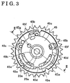
- Fig. 3 is a front view viewed from an arrow A of Fig. 1;
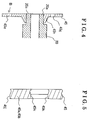
- Fig. 4 is a longitudinal sectional view of press fit portions of a sensor wheel and a boss portion respectively taken along the line II-II of Fig. 3;
- Fig. 5 is a detail view of B portion of Fig. 4; and
- Fig. 6 is an explanation view showing a rotational torque of the press fit portions of the sensor wheel and the boss portion.
- An embodiment of the present invention is explained referring to attached drawings.
- A variable valve timing control device shown in Figs. 1 to 5 includes a rotor 20 (rotor member) integrally fixed to a tip end portion of a
camshaft 10 being rotatably supported on acylinder head 110 of an internal combustion engine, and a housing 30 (housing member) connected to acrankshaft 130 via a timing chain 120 (drive force transmitting member) and assembled to an outer periphery of therotor 20, being rotatable relative to therotor 20 within a predetermined range. Atiming sprocket 31 is integrally formed on an outer periphery of thehousing 30. The variable valve timing control device also includes fourvanes 70 assembled to therotor 20. An advancedangle fluid passage 11 and a retardedangle fluid passage 12 through which an operation fluid is supplied to or discharged from an advanced angle chamber R1 and a retarded angle chamber R2 (to be mentioned later) are formed on thecamshaft 10, extending in the axial direction thereof. Thetiming sprocket 31 receives a rotation force from thecrankshaft 130 via a crank sprocket (not shown) and thetiming chain 120. According to a structure of the present embodiment, the rotation force of thecrankshaft 130 of the internal combustion engine is transmitted to thetiming sprocket 31 of thehousing 30. However, the embodiment is not limited to the above structure. For example, a belt member instead of thetiming chain 120 and a pulley instead of thetiming sprocket 31 may be employed. - The
rotor 20 having a stepped cylindrical shape includes aboss portion 20a and a penetratingbore 20b at a center in the axial direction of therotor 20. Therotor 20 also includes aconcave portion 20d at an end face to which thecamshaft 10 is assembled. Thecamshaft 10 is located in theconcave portion 20d. A single installation bolt 90 is in contact with aseating face 20c formed on an end face of theboss portion 20a with passing through the penetratingbore 20b and fastened to thecamshaft 10 for fixing therotor 20. Asensor wheel 45 for detecting a rotational angle of thecamshaft 10 is press fit to anouter periphery 20e of theboss portion 20a. - As shown in Fig. 3, the
sensor wheel 45 having a substantially circular disk shape includes two projectingportions 45a extending in the circumferential direction of thesensor wheel 45, and two projectingportions 45b whose length in the circumferential direction is shorter than that of the projectingportions 45a. The projectingportions rotor 20 and formed on the outer circumference of thesensor wheel 45.Respective grooves portions elongated holes sensor wheel 45 in the radially inward direction relative to the projectingportions sensor wheel 45. A sensor 95 (shown in Fig. 1) for detecting the rotational angle of therotor 20 is provided at an engine side, facing to the projectingportions elongated holes sensor wheel 45. In addition, areference hole 45g having a circular shape is formed on thesensor wheel 45 in the radially inward direction relative to theelongated holes sensor wheel 45 is press fit to theboss portion 20a of therotor 20, a fixing jig (not shown) is inserted into thereference hole 45g for determining the position of thesensor wheel 45 in the circumferential direction. Thus, the deformation of the projectingportions reference hole 45g on thesensor wheel 45, thereby preventing a rotational displacement of thesensor wheel 45 relative to therotor 20 due to the fluctuation torque of the cam and the like. Thereference hole 45g may have an elongated shape, an oval shape, or the like. In addition, a plurality of thereference holes 45g may be formed on thesensor wheel 45. - As shown in Fig. 4, an extending
portion 45h of thesensor wheel 45 is press fit to theboss portion 20a of therotor 20. An axial end face of the extendingportion 45h (left side in Fig. 4) and an axial end face of theboss portion 20a (left side in Fig. 4) are positioned on an identical plane. Thus, thesensor wheel 45 is press fit to theboss portion 20a of therotor 20 until the axial end face of theboss portion 20a becomes in contact with a face of the fixing jig positioned on the identical plane to that of the extendingportion 45h or theboss portion 20a. As a result, the press fit amount of thesensor wheel 45 to theboss portion 20a may be easily controlled to thereby appropriately assure a distance between thesensor wheel 45 and thesensor 95. The axial end face of theboss portion 20a is equal to theseating face 20c in contact with the bolt 90. In addition, the extendingportion 45h of thesensor wheel 45 press fit to theboss portion 20a has a conical shape whose outer circumference is gradually reduced in a direction in which thesensor wheel 45 is extending. Therefore, thesensor wheel 45 is prevented from interfering with an inner radial portion of a front plate 32 (housing member) arranged adjacent to thesensor wheel 45. In addition, an axial length of the variable valve timing control device may be reduced to thereby achieve a downsizing of the device. As shown in Fig. 6, the extendingportion 45h with the conical shape assures the same level of press fit length as in the case of a cylindrical shape being employed for the extendingportion 45h. That is, a rotational torque at which a displacement is caused between press fit portions of thesensor wheel 45 and theboss portion 20a (i.e. thesensor wheel 45 and theboss portion 20a starts rotating relative to each other) may be the same level as in the case of the cylindrical shape being employed for the extendingportion 45h. Thus, the rotational displacement between thesensor wheel 45 and therotor 20 may be prevented. - The
sensor wheel 45 is press-molded. A sectional face extending on the rotational axis of the projectingportions elongated holes linear portions portions elongated holes sensor 95 may be prevented. Thelinear portions - As shown in Fig. 2, four
vane grooves 21, a receivinggroove 22, and four firstfluid passages 23 and four secondfluid passages 24 extending in the radial direction of therotor 20 are formed on therotor 20. The fourvanes 70 are positioned in thevane grooves 21 respectively, being movable in the radial direction of therotor 20. Aleaf spring 25 is disposed between a bottom portion of eachvane groove 21 and a bottom face of eachvane 70. Eachvane 70 is biased in the radially outward direction by theleaf spring 25 and is slidable on the inner circumferential face of thehousing 30. In a state shown in Fig. 2, i.e. when a relative phase between thecamshaft 10 and therotor 20, and thehousing 30 is positioned at a predetermined phase (i.e. most retarded angle phase), a head portion of alock key 80 is inserted into the receivinggroove 22 by a predetermined amount. The receivinggroove 22 is connected to thefirst fluid passage 23. - The
housing 30 is assembled on an outer periphery of therotor 20, being rotatable relative thereto within a predetermined angle range. Thetiming sprocket 31 is integrally formed on an outer periphery of thehousing 30. - Four
convex portions 33 are formed on an inner circumference of thehousing 30 in the circumferential direction thereof, projecting in the radially inward direction. Each inner circumferential face of theconvex portion 33 is slidably in contact with an outer circumferential face of therotor 20. That is, thehousing 30 is rotatably supported on therotor 20. A retractinggroove 34 for accommodating thelock key 80, and aspring receiving groove 35 connected to the retractinggroove 34 for accommodating aspring 81 that biases thelock key 80 in the radially inward direction of thehousing 30 are formed on one of theconvex portions 33. - Each
vane 70 divides a fluid pressure chamber R0 formed between thehousing 30 and therotor 20, and also between theconvex portions 33 adjacent to each other in the circumferential direction into the advanced angle chamber R1 and the retarded angle chamber R2. The relative rotation between therotor 20 and thehousing 30 on the most advanced angle side is restricted at a position where thevane 70, i.e. avane 70a in Fig. 2, is in contact with oneside face 33a of theconvex portion 33 in the circumferential direction. Meanwhile, the relative rotation between therotor 20 and thehousing 30 on the most retarded angle side is restricted at a position where thevane 70, i.e. avane 70b in Fig. 2, is in contact with theother side face 33b of theconvex portion 33 in the circumferential direction. At this time, the head portion of thelock key 80 is positioned in the receivinggroove 22 for restricting the relative rotation between therotor 20 and thehousing 30 according to the present embodiment. - According to the above-mentioned embodiment, a desired valve timing may be obtained by controlling the fluid pressure in each advanced angle chamber R1 and retarded angle chamber R2 for controlling the relative rotation of the
rotor 20 to thehousing 30. At this time, a rotational phase of thesensor wheel 45 integrally rotating with therotor 20 that is detected by thesensor 95, and a rotational phase of the crankshaft that is detected by a sensor (not shown) provided at a crankshaft portion, are compared for determining whether a desired valve timing has been obtained. - When the internal combustion engine is stopped, the head portion of the
lock key 80 is inserted into the receivinggroove 22 by a predetermined amount and thus the relative rotation between therotor 20 and thehousing 30 is locked, i.e. restricted at the most retarded angle phase. - After the internal combustion engine is started and the advanced angle phase is required for the valve timing depending on the operation condition of the internal combustion engine, the operation fluid (fluid pressure) supplied from an oil pump (not shown) is provided to the advanced angle chamber R1 by passing through the advanced
angle fluid passage 11 and thefirst fluid passage 23. The operation fluid is also provided to the receivinggroove 22 via thepassage 23. Meanwhile, the operation fluid stored in the retarded angle chamber R2 is sent to thesecond fluid passage 24 and the retardedangle fluid passage 12 to be discharged from a switching valve (not shown) to an oil pan (not shown). At this time, thelock key 80 is moved against the biasing force of thespring 81. Then, the head portion of thelock key 80 is retracted from the receivinggroove 22 to thereby release the locked state between therotor 20 and thehousing 30. Therefore, therotor 20 and eachvane 70 may be rotated to the advanced angle side R (see Fig. 2) relative to thehousing 30. - When the retarded angle phase is required for the valve timing depending on the operation condition of the internal combustion engine, the operation fluid supplied from the oil pump is provided to the retarded angle chamber R2 by passing through the retarded
angle fluid passage 12 and the second fluid passage due to the operation of the switching valve. Meanwhile, the operation fluid stored in the advanced angle chamber R1 is sent to thefirst fluid passage 23 and the advancedangle fluid passage 11 to be discharged from the switching valve to the oil pan. Therefore, therotor 20 and eachvane 70 may be rotated to the retarded angle side relative to thehousing 30. - According to the aforementioned embodiment, when the
sensor wheel 45 is press fit to theboss portion 20a formed on therotor 20 in the axial direction thereof, the axial end face of thesensor wheel 45 and the axial end face of theboss portion 20a are positioned on the identical plane. Thus, thesensor wheel 45 may be press fit to theboss portion 20a until theboss portion 20a becomes in contact with the face of the fixing jig positioned on the identical plane to the axial end faces of theboss portion 20a and thesensor wheel 45. The press fit amount of thesensor wheel 45 into theboss portion 20a may be easily controlled. - Further, according to the aforementioned embodiment, the extending
portion 45h of thesensor wheel 45 press fit to theboss portion 20a has a conical shape whose outer circumference is gradually reduced in a direction in which thesensor wheel 45 is extending. Thus, the outer diameter of the extendingportion 45h of thesensor wheel 45 may be reduced with assuring the press fit length into theboss portion 20a. Thesensor wheel 45 is prevented from interfering with thehousing 30 provided adjacent to thesensor wheel 45, thereby reducing a length of the variable valve timing control device in the axial direction thereof and achieving a downsizing. - Furthermore, according to the aforementioned embodiment, the
sensor wheel 45 is press-molded. The sectional face extending on the rotational axis of the projectingportions linear portions - The principles, preferred embodiment and mode of operation of the present invention have been described in the foregoing specification. However, the invention which is intended to be protected is not to be construed as limited to the particular embodiments disclosed. Further, the embodiments described herein are to be regarded as illustrative rather than restrictive. Variations and changes may be made by others, and equivalents employed, without departing from the sprit of the present invention. Accordingly, it is expressly intended that all such variations, changes and equivalents which fall within the spirit and scope of the present invention as defined in the claims, be embraced thereby.
- It is explicitly stated that all features disclosed in the description and/or the claims are intended to be disclosed separately and independently from each other for the purpose of original disclosure as well as for the purpose of restricting the claimed invention independent of the composition of the features in the embodiments and/or the claims. It is explicitly stated that all value ranges or indications of groups of entities disclose every possible intermediate value or intermediate entity for the purpose of original disclosure as well as for the purpose of restricting the claimed invention, in particular as limits of value ranges.
Claims (4)
- A variable valve timing control device comprising a rotor member (20) integrally connected to either one of a camshaft (10) and a crankshaft, either one of the camshaft and the crankshaft being rotatably assembled to an internal combustion engine, a housing member (30) connected to either one of the crankshaft and the camshaft via a driving force transmitting member and assembled to the rotor member so as to be rotatable relative thereto, and a sensor wheel (45) assembled to either one of the rotor member and the housing member and including a projecting portion (45a, 45b) for detecting a rotational angle of the rotor member or the housing member by using a sensor (95) provided adjacent to the sensor wheel characterized in that the sensor wheel includes at least one reference hole (45g) for determining a position of the projecting portion in a circumferential direction of the sensor wheel.
- A variable valve timing control device according to claim 1, wherein the sensor wheel is press fit to a boss portion (20a) formed on the rotor member in an axial direction thereof, and an axial end face of the sensor wheel and an axial end face of the boss portion are positioned on an identical plane.
- A variable valve timing control device according to claim 2, wherein the sensor wheel includes an extending portion to be press fit to the boss portion and whose outer circumference is gradually reduced in a direction where the extending portion is extending.
- A variable valve timing control device according to one of claims 1 to 3, wherein the sensor wheel is press-molded and a sectional face extending on a rotational axis of the projecting portion includes a linear portion (45j, 45k) in parallel with the rotational axis.
Applications Claiming Priority (2)
| Application Number | Priority Date | Filing Date | Title |
|---|---|---|---|
| JP2003185603 | 2003-06-27 | ||
| JP2003185603A JP2005016482A (en) | 2003-06-27 | 2003-06-27 | Valve timing control device |
Publications (2)
| Publication Number | Publication Date |
|---|---|
| EP1491727A2 true EP1491727A2 (en) | 2004-12-29 |
| EP1491727A3 EP1491727A3 (en) | 2005-11-30 |
Family
ID=33411156
Family Applications (1)
| Application Number | Title | Priority Date | Filing Date |
|---|---|---|---|
| EP04014611A Withdrawn EP1491727A3 (en) | 2003-06-27 | 2004-06-22 | Variable valve timing control device |
Country Status (4)
| Country | Link |
|---|---|
| US (1) | US6994062B2 (en) |
| EP (1) | EP1491727A3 (en) |
| JP (1) | JP2005016482A (en) |
| CN (1) | CN1576523A (en) |
Cited By (1)
| Publication number | Priority date | Publication date | Assignee | Title |
|---|---|---|---|---|
| DE102006016650B4 (en) * | 2006-04-08 | 2019-05-16 | Schaeffler Technologies AG & Co. KG | Camshaft drive for an internal combustion engine |
Families Citing this family (18)
| Publication number | Priority date | Publication date | Assignee | Title |
|---|---|---|---|---|
| US7056321B2 (en) * | 2000-08-01 | 2006-06-06 | Endius, Incorporated | Method of securing vertebrae |
| JP4379730B2 (en) * | 2005-03-11 | 2009-12-09 | アイシン精機株式会社 | Valve timing control device |
| JP4626819B2 (en) * | 2006-03-29 | 2011-02-09 | アイシン精機株式会社 | Valve timing control device |
| KR100839540B1 (en) | 2006-06-27 | 2008-06-19 | 주식회사 케이티프리텔 | Method, device and recording medium recording method for providing driving information based on real time traffic information |
| DE102006033425A1 (en) * | 2006-07-19 | 2008-02-21 | Schaeffler Kg | Group of several camshafts with camshaft adjusters |
| US12038438B2 (en) | 2008-07-18 | 2024-07-16 | Bio-Rad Laboratories, Inc. | Enzyme quantification |
| JP4895234B2 (en) * | 2009-04-09 | 2012-03-14 | 株式会社デンソー | Valve timing adjustment device |
| JP5382440B2 (en) * | 2009-09-25 | 2014-01-08 | アイシン精機株式会社 | Valve timing control device |
| US9399797B2 (en) | 2010-02-12 | 2016-07-26 | Raindance Technologies, Inc. | Digital analyte analysis |
| JP5934657B2 (en) | 2010-02-12 | 2016-06-15 | レインダンス テクノロジーズ, インコーポレイテッド | Digital specimen analysis |
| EP2675819B1 (en) | 2011-02-18 | 2020-04-08 | Bio-Rad Laboratories, Inc. | Compositions and methods for molecular labeling |
| JP5553174B2 (en) * | 2011-03-23 | 2014-07-16 | 株式会社デンソー | Valve timing adjustment device |
| US8658430B2 (en) | 2011-07-20 | 2014-02-25 | Raindance Technologies, Inc. | Manipulating droplet size |
| US9080516B2 (en) * | 2011-09-20 | 2015-07-14 | GM Global Technology Operations LLC | Diagnostic system and method for a variable valve lift mechanism |
| US8714123B2 (en) * | 2012-01-18 | 2014-05-06 | Ford Global Technologies, Llc | Oil pressure modification for variable cam timing |
| JP2013194544A (en) * | 2012-03-16 | 2013-09-30 | Ohashi Technica Inc | Sensor plate and camshaft with the sensor plate |
| US10815844B2 (en) * | 2019-03-26 | 2020-10-27 | Schaeffler Technologies AG & Co. KG | Camshaft phaser with pin |
| WO2021005704A1 (en) * | 2019-07-09 | 2021-01-14 | 株式会社ミクニ | Valve timing changer |
Family Cites Families (5)
| Publication number | Priority date | Publication date | Assignee | Title |
|---|---|---|---|---|
| US5715780A (en) * | 1996-10-21 | 1998-02-10 | General Motors Corporation | Cam phaser position detection |
| JP3988376B2 (en) * | 2000-10-23 | 2007-10-10 | 日産自動車株式会社 | Reference position learning device for variable valve timing device |
| JP4012378B2 (en) * | 2000-11-28 | 2007-11-21 | 株式会社日立製作所 | Valve timing control device for internal combustion engine |
| US6609498B2 (en) * | 2001-07-02 | 2003-08-26 | General Motors Corporation | Target wheel tooth detection |
| JP4032288B2 (en) * | 2002-03-28 | 2008-01-16 | アイシン精機株式会社 | Valve timing control device |
-
2003
- 2003-06-27 JP JP2003185603A patent/JP2005016482A/en active Pending
-
2004
- 2004-06-22 EP EP04014611A patent/EP1491727A3/en not_active Withdrawn
- 2004-06-25 CN CN200410062821.4A patent/CN1576523A/en active Pending
- 2004-06-28 US US10/876,588 patent/US6994062B2/en not_active Expired - Fee Related
Cited By (1)
| Publication number | Priority date | Publication date | Assignee | Title |
|---|---|---|---|---|
| DE102006016650B4 (en) * | 2006-04-08 | 2019-05-16 | Schaeffler Technologies AG & Co. KG | Camshaft drive for an internal combustion engine |
Also Published As
| Publication number | Publication date |
|---|---|
| CN1576523A (en) | 2005-02-09 |
| EP1491727A3 (en) | 2005-11-30 |
| US20050022764A1 (en) | 2005-02-03 |
| US6994062B2 (en) | 2006-02-07 |
| JP2005016482A (en) | 2005-01-20 |
Similar Documents
| Publication | Publication Date | Title |
|---|---|---|
| US6994062B2 (en) | Variable valve timing control device | |
| EP0806550B2 (en) | Valve timing control device | |
| US6439181B1 (en) | Variable valve timing system | |
| JP4016020B2 (en) | Valve timing control device for internal combustion engine | |
| US6497208B2 (en) | Variable valve control apparatus for an internal combustion engine | |
| US6662769B2 (en) | Valve timing control device | |
| US6439182B1 (en) | Valve timing adjusting device having stopper piston | |
| JPH11241608A (en) | Valve timing adjustment mechanism for internal combustion engine | |
| EP1500796A2 (en) | Camshaft phasing device | |
| US6827052B2 (en) | Variable valve timing device | |
| JP2002227622A (en) | Valve timing control device for internal combustion engine | |
| US6394052B2 (en) | Variable valve control apparatus for an internal combustion engine | |
| EP1486644A1 (en) | Vane type phaser with locking pin | |
| US7311069B2 (en) | Variable valve timing control device | |
| EP1703088A1 (en) | Variable valve time control device | |
| JP5057232B2 (en) | Valve timing adjusting device and manufacturing method thereof | |
| JPH09250310A (en) | Valve timing changing device for internal combustion engine | |
| EP1491728B1 (en) | Variable valve timing control device | |
| JPH10159519A (en) | Valve timing control device for internal combustion engine | |
| JP4304219B2 (en) | Valve timing control device for internal combustion engine and assembly method thereof | |
| US6701878B2 (en) | Variable valve timing device | |
| JP4338326B2 (en) | Valve timing adjustment device | |
| US20080245328A1 (en) | Valve Timing Adjusting Device | |
| JPH09250311A (en) | Valve timing changing device for internal combustion engine | |
| JPH10252420A (en) | Valve timing control device |
Legal Events
| Date | Code | Title | Description |
|---|---|---|---|
| PUAI | Public reference made under article 153(3) epc to a published international application that has entered the european phase |
Free format text: ORIGINAL CODE: 0009012 |
|
| AK | Designated contracting states |
Kind code of ref document: A2 Designated state(s): AT BE BG CH CY CZ DE DK EE ES FI FR GB GR HU IE IT LI LU MC NL PL PT RO SE SI SK TR |
|
| AX | Request for extension of the european patent |
Extension state: AL HR LT LV MK |
|
| PUAL | Search report despatched |
Free format text: ORIGINAL CODE: 0009013 |
|
| AK | Designated contracting states |
Kind code of ref document: A3 Designated state(s): AT BE BG CH CY CZ DE DK EE ES FI FR GB GR HU IE IT LI LU MC NL PL PT RO SE SI SK TR |
|
| AX | Request for extension of the european patent |
Extension state: AL HR LT LV MK |
|
| 17P | Request for examination filed |
Effective date: 20060526 |
|
| AKX | Designation fees paid |
Designated state(s): CZ DE FR GB |
|
| STAA | Information on the status of an ep patent application or granted ep patent |
Free format text: STATUS: THE APPLICATION HAS BEEN WITHDRAWN |
|
| 18W | Application withdrawn |
Effective date: 20070712 |