EP1491358A2 - Paired optically variable device - Google Patents
Paired optically variable device Download PDFInfo
- Publication number
- EP1491358A2 EP1491358A2 EP04023481A EP04023481A EP1491358A2 EP 1491358 A2 EP1491358 A2 EP 1491358A2 EP 04023481 A EP04023481 A EP 04023481A EP 04023481 A EP04023481 A EP 04023481A EP 1491358 A2 EP1491358 A2 EP 1491358A2
- Authority
- EP
- European Patent Office
- Prior art keywords
- optically variable
- color
- paired
- angle
- pigments
- Prior art date
- Legal status (The legal status is an assumption and is not a legal conclusion. Google has not performed a legal analysis and makes no representation as to the accuracy of the status listed.)
- Withdrawn
Links
Images


Classifications
-
- B—PERFORMING OPERATIONS; TRANSPORTING
- B42—BOOKBINDING; ALBUMS; FILES; SPECIAL PRINTED MATTER
- B42D—BOOKS; BOOK COVERS; LOOSE LEAVES; PRINTED MATTER CHARACTERISED BY IDENTIFICATION OR SECURITY FEATURES; PRINTED MATTER OF SPECIAL FORMAT OR STYLE NOT OTHERWISE PROVIDED FOR; DEVICES FOR USE THEREWITH AND NOT OTHERWISE PROVIDED FOR; MOVABLE-STRIP WRITING OR READING APPARATUS
- B42D25/00—Information-bearing cards or sheet-like structures characterised by identification or security features; Manufacture thereof
- B42D25/30—Identification or security features, e.g. for preventing forgery
- B42D25/36—Identification or security features, e.g. for preventing forgery comprising special materials
-
- B—PERFORMING OPERATIONS; TRANSPORTING
- B05—SPRAYING OR ATOMISING IN GENERAL; APPLYING FLUENT MATERIALS TO SURFACES, IN GENERAL
- B05D—PROCESSES FOR APPLYING FLUENT MATERIALS TO SURFACES, IN GENERAL
- B05D5/00—Processes for applying liquids or other fluent materials to surfaces to obtain special surface effects, finishes or structures
- B05D5/06—Processes for applying liquids or other fluent materials to surfaces to obtain special surface effects, finishes or structures to obtain multicolour or other optical effects
-
- B—PERFORMING OPERATIONS; TRANSPORTING
- B05—SPRAYING OR ATOMISING IN GENERAL; APPLYING FLUENT MATERIALS TO SURFACES, IN GENERAL
- B05D—PROCESSES FOR APPLYING FLUENT MATERIALS TO SURFACES, IN GENERAL
- B05D1/00—Processes for applying liquids or other fluent materials
- B05D1/28—Processes for applying liquids or other fluent materials performed by transfer from the surfaces of elements carrying the liquid or other fluent material, e.g. brushes, pads, rollers
- B05D1/286—Processes for applying liquids or other fluent materials performed by transfer from the surfaces of elements carrying the liquid or other fluent material, e.g. brushes, pads, rollers using a temporary backing to which the coating has been applied
-
- B—PERFORMING OPERATIONS; TRANSPORTING
- B29—WORKING OF PLASTICS; WORKING OF SUBSTANCES IN A PLASTIC STATE IN GENERAL
- B29C—SHAPING OR JOINING OF PLASTICS; SHAPING OF MATERIAL IN A PLASTIC STATE, NOT OTHERWISE PROVIDED FOR; AFTER-TREATMENT OF THE SHAPED PRODUCTS, e.g. REPAIRING
- B29C70/00—Shaping composites, i.e. plastics material comprising reinforcements, fillers or preformed parts, e.g. inserts
- B29C70/58—Shaping composites, i.e. plastics material comprising reinforcements, fillers or preformed parts, e.g. inserts comprising fillers only, e.g. particles, powder, beads, flakes, spheres
- B29C70/585—Shaping composites, i.e. plastics material comprising reinforcements, fillers or preformed parts, e.g. inserts comprising fillers only, e.g. particles, powder, beads, flakes, spheres incorporation of light reflecting filler, e.g. lamellae to obtain pearlescent effet
-
- B—PERFORMING OPERATIONS; TRANSPORTING
- B41—PRINTING; LINING MACHINES; TYPEWRITERS; STAMPS
- B41M—PRINTING, DUPLICATING, MARKING, OR COPYING PROCESSES; COLOUR PRINTING
- B41M3/00—Printing processes to produce particular kinds of printed work, e.g. patterns
-
- B—PERFORMING OPERATIONS; TRANSPORTING
- B41—PRINTING; LINING MACHINES; TYPEWRITERS; STAMPS
- B41M—PRINTING, DUPLICATING, MARKING, OR COPYING PROCESSES; COLOUR PRINTING
- B41M3/00—Printing processes to produce particular kinds of printed work, e.g. patterns
- B41M3/06—Veined printings; Fluorescent printings; Stereoscopic images; Imitated patterns, e.g. tissues, textiles
-
- B—PERFORMING OPERATIONS; TRANSPORTING
- B41—PRINTING; LINING MACHINES; TYPEWRITERS; STAMPS
- B41M—PRINTING, DUPLICATING, MARKING, OR COPYING PROCESSES; COLOUR PRINTING
- B41M3/00—Printing processes to produce particular kinds of printed work, e.g. patterns
- B41M3/14—Security printing
-
- B—PERFORMING OPERATIONS; TRANSPORTING
- B41—PRINTING; LINING MACHINES; TYPEWRITERS; STAMPS
- B41M—PRINTING, DUPLICATING, MARKING, OR COPYING PROCESSES; COLOUR PRINTING
- B41M3/00—Printing processes to produce particular kinds of printed work, e.g. patterns
- B41M3/14—Security printing
- B41M3/148—Transitory images, i.e. images only visible from certain viewing angles
-
- B—PERFORMING OPERATIONS; TRANSPORTING
- B42—BOOKBINDING; ALBUMS; FILES; SPECIAL PRINTED MATTER
- B42D—BOOKS; BOOK COVERS; LOOSE LEAVES; PRINTED MATTER CHARACTERISED BY IDENTIFICATION OR SECURITY FEATURES; PRINTED MATTER OF SPECIAL FORMAT OR STYLE NOT OTHERWISE PROVIDED FOR; DEVICES FOR USE THEREWITH AND NOT OTHERWISE PROVIDED FOR; MOVABLE-STRIP WRITING OR READING APPARATUS
- B42D25/00—Information-bearing cards or sheet-like structures characterised by identification or security features; Manufacture thereof
- B42D25/20—Information-bearing cards or sheet-like structures characterised by identification or security features; Manufacture thereof characterised by a particular use or purpose
- B42D25/29—Securities; Bank notes
-
- B—PERFORMING OPERATIONS; TRANSPORTING
- B42—BOOKBINDING; ALBUMS; FILES; SPECIAL PRINTED MATTER
- B42D—BOOKS; BOOK COVERS; LOOSE LEAVES; PRINTED MATTER CHARACTERISED BY IDENTIFICATION OR SECURITY FEATURES; PRINTED MATTER OF SPECIAL FORMAT OR STYLE NOT OTHERWISE PROVIDED FOR; DEVICES FOR USE THEREWITH AND NOT OTHERWISE PROVIDED FOR; MOVABLE-STRIP WRITING OR READING APPARATUS
- B42D25/00—Information-bearing cards or sheet-like structures characterised by identification or security features; Manufacture thereof
- B42D25/30—Identification or security features, e.g. for preventing forgery
- B42D25/36—Identification or security features, e.g. for preventing forgery comprising special materials
- B42D25/378—Special inks
-
- B—PERFORMING OPERATIONS; TRANSPORTING
- B44—DECORATIVE ARTS
- B44F—SPECIAL DESIGNS OR PICTURES
- B44F1/00—Designs or pictures characterised by special or unusual light effects
- B44F1/08—Designs or pictures characterised by special or unusual light effects characterised by colour effects
-
- C—CHEMISTRY; METALLURGY
- C03—GLASS; MINERAL OR SLAG WOOL
- C03C—CHEMICAL COMPOSITION OF GLASSES, GLAZES OR VITREOUS ENAMELS; SURFACE TREATMENT OF GLASS; SURFACE TREATMENT OF FIBRES OR FILAMENTS MADE FROM GLASS, MINERALS OR SLAGS; JOINING GLASS TO GLASS OR OTHER MATERIALS
- C03C17/00—Surface treatment of glass, not in the form of fibres or filaments, by coating
-
- C—CHEMISTRY; METALLURGY
- C09—DYES; PAINTS; POLISHES; NATURAL RESINS; ADHESIVES; COMPOSITIONS NOT OTHERWISE PROVIDED FOR; APPLICATIONS OF MATERIALS NOT OTHERWISE PROVIDED FOR
- C09C—TREATMENT OF INORGANIC MATERIALS, OTHER THAN FIBROUS FILLERS, TO ENHANCE THEIR PIGMENTING OR FILLING PROPERTIES ; PREPARATION OF CARBON BLACK ; PREPARATION OF INORGANIC MATERIALS WHICH ARE NO SINGLE CHEMICAL COMPOUNDS AND WHICH ARE MAINLY USED AS PIGMENTS OR FILLERS
- C09C1/00—Treatment of specific inorganic materials other than fibrous fillers; Preparation of carbon black
- C09C1/0015—Pigments exhibiting interference colours, e.g. transparent platelets of appropriate thinness or flaky substrates, e.g. mica, bearing appropriate thin transparent coatings
-
- C—CHEMISTRY; METALLURGY
- C09—DYES; PAINTS; POLISHES; NATURAL RESINS; ADHESIVES; COMPOSITIONS NOT OTHERWISE PROVIDED FOR; APPLICATIONS OF MATERIALS NOT OTHERWISE PROVIDED FOR
- C09C—TREATMENT OF INORGANIC MATERIALS, OTHER THAN FIBROUS FILLERS, TO ENHANCE THEIR PIGMENTING OR FILLING PROPERTIES ; PREPARATION OF CARBON BLACK ; PREPARATION OF INORGANIC MATERIALS WHICH ARE NO SINGLE CHEMICAL COMPOUNDS AND WHICH ARE MAINLY USED AS PIGMENTS OR FILLERS
- C09C1/00—Treatment of specific inorganic materials other than fibrous fillers; Preparation of carbon black
- C09C1/0078—Pigments consisting of flaky, non-metallic substrates, characterised by a surface-region containing free metal
-
- C—CHEMISTRY; METALLURGY
- C09—DYES; PAINTS; POLISHES; NATURAL RESINS; ADHESIVES; COMPOSITIONS NOT OTHERWISE PROVIDED FOR; APPLICATIONS OF MATERIALS NOT OTHERWISE PROVIDED FOR
- C09D—COATING COMPOSITIONS, e.g. PAINTS, VARNISHES OR LACQUERS; FILLING PASTES; CHEMICAL PAINT OR INK REMOVERS; INKS; CORRECTING FLUIDS; WOODSTAINS; PASTES OR SOLIDS FOR COLOURING OR PRINTING; USE OF MATERIALS THEREFOR
- C09D11/00—Inks
- C09D11/50—Sympathetic, colour changing or similar inks
-
- C—CHEMISTRY; METALLURGY
- C09—DYES; PAINTS; POLISHES; NATURAL RESINS; ADHESIVES; COMPOSITIONS NOT OTHERWISE PROVIDED FOR; APPLICATIONS OF MATERIALS NOT OTHERWISE PROVIDED FOR
- C09D—COATING COMPOSITIONS, e.g. PAINTS, VARNISHES OR LACQUERS; FILLING PASTES; CHEMICAL PAINT OR INK REMOVERS; INKS; CORRECTING FLUIDS; WOODSTAINS; PASTES OR SOLIDS FOR COLOURING OR PRINTING; USE OF MATERIALS THEREFOR
- C09D5/00—Coating compositions, e.g. paints, varnishes or lacquers, characterised by their physical nature or the effects produced; Filling pastes
- C09D5/36—Pearl essence, e.g. coatings containing platelet-like pigments for pearl lustre
-
- F—MECHANICAL ENGINEERING; LIGHTING; HEATING; WEAPONS; BLASTING
- F24—HEATING; RANGES; VENTILATING
- F24S—SOLAR HEAT COLLECTORS; SOLAR HEAT SYSTEMS
- F24S70/00—Details of absorbing elements
- F24S70/20—Details of absorbing elements characterised by absorbing coatings; characterised by surface treatment for increasing absorption
- F24S70/225—Details of absorbing elements characterised by absorbing coatings; characterised by surface treatment for increasing absorption for spectrally selective absorption
-
- G—PHYSICS
- G02—OPTICS
- G02B—OPTICAL ELEMENTS, SYSTEMS OR APPARATUS
- G02B5/00—Optical elements other than lenses
- G02B5/20—Filters
- G02B5/22—Absorbing filters
- G02B5/223—Absorbing filters containing organic substances, e.g. dyes, inks or pigments
-
- G—PHYSICS
- G02—OPTICS
- G02B—OPTICAL ELEMENTS, SYSTEMS OR APPARATUS
- G02B5/00—Optical elements other than lenses
- G02B5/20—Filters
- G02B5/28—Interference filters
- G02B5/285—Interference filters comprising deposited thin solid films
-
- B42D2035/24—
-
- C—CHEMISTRY; METALLURGY
- C01—INORGANIC CHEMISTRY
- C01P—INDEXING SCHEME RELATING TO STRUCTURAL AND PHYSICAL ASPECTS OF SOLID INORGANIC COMPOUNDS
- C01P2004/00—Particle morphology
- C01P2004/54—Particles characterised by their aspect ratio, i.e. the ratio of sizes in the longest to the shortest dimension
-
- C—CHEMISTRY; METALLURGY
- C09—DYES; PAINTS; POLISHES; NATURAL RESINS; ADHESIVES; COMPOSITIONS NOT OTHERWISE PROVIDED FOR; APPLICATIONS OF MATERIALS NOT OTHERWISE PROVIDED FOR
- C09C—TREATMENT OF INORGANIC MATERIALS, OTHER THAN FIBROUS FILLERS, TO ENHANCE THEIR PIGMENTING OR FILLING PROPERTIES ; PREPARATION OF CARBON BLACK ; PREPARATION OF INORGANIC MATERIALS WHICH ARE NO SINGLE CHEMICAL COMPOUNDS AND WHICH ARE MAINLY USED AS PIGMENTS OR FILLERS
- C09C2200/00—Compositional and structural details of pigments exhibiting interference colours
- C09C2200/24—Interference pigments comprising a metallic reflector or absorber layer, which is not adjacent to the core
-
- C—CHEMISTRY; METALLURGY
- C09—DYES; PAINTS; POLISHES; NATURAL RESINS; ADHESIVES; COMPOSITIONS NOT OTHERWISE PROVIDED FOR; APPLICATIONS OF MATERIALS NOT OTHERWISE PROVIDED FOR
- C09C—TREATMENT OF INORGANIC MATERIALS, OTHER THAN FIBROUS FILLERS, TO ENHANCE THEIR PIGMENTING OR FILLING PROPERTIES ; PREPARATION OF CARBON BLACK ; PREPARATION OF INORGANIC MATERIALS WHICH ARE NO SINGLE CHEMICAL COMPOUNDS AND WHICH ARE MAINLY USED AS PIGMENTS OR FILLERS
- C09C2200/00—Compositional and structural details of pigments exhibiting interference colours
- C09C2200/30—Interference pigments characterised by the thickness of the core or layers thereon or by the total thickness of the final pigment particle
- C09C2200/303—Thickness of a layer with low refractive material
-
- C—CHEMISTRY; METALLURGY
- C09—DYES; PAINTS; POLISHES; NATURAL RESINS; ADHESIVES; COMPOSITIONS NOT OTHERWISE PROVIDED FOR; APPLICATIONS OF MATERIALS NOT OTHERWISE PROVIDED FOR
- C09C—TREATMENT OF INORGANIC MATERIALS, OTHER THAN FIBROUS FILLERS, TO ENHANCE THEIR PIGMENTING OR FILLING PROPERTIES ; PREPARATION OF CARBON BLACK ; PREPARATION OF INORGANIC MATERIALS WHICH ARE NO SINGLE CHEMICAL COMPOUNDS AND WHICH ARE MAINLY USED AS PIGMENTS OR FILLERS
- C09C2220/00—Methods of preparing the interference pigments
- C09C2220/20—PVD, CVD methods or coating in a gas-phase using a fluidized bed
-
- Y—GENERAL TAGGING OF NEW TECHNOLOGICAL DEVELOPMENTS; GENERAL TAGGING OF CROSS-SECTIONAL TECHNOLOGIES SPANNING OVER SEVERAL SECTIONS OF THE IPC; TECHNICAL SUBJECTS COVERED BY FORMER USPC CROSS-REFERENCE ART COLLECTIONS [XRACs] AND DIGESTS
- Y02—TECHNOLOGIES OR APPLICATIONS FOR MITIGATION OR ADAPTATION AGAINST CLIMATE CHANGE
- Y02E—REDUCTION OF GREENHOUSE GAS [GHG] EMISSIONS, RELATED TO ENERGY GENERATION, TRANSMISSION OR DISTRIBUTION
- Y02E10/00—Energy generation through renewable energy sources
- Y02E10/40—Solar thermal energy, e.g. solar towers
-
- Y—GENERAL TAGGING OF NEW TECHNOLOGICAL DEVELOPMENTS; GENERAL TAGGING OF CROSS-SECTIONAL TECHNOLOGIES SPANNING OVER SEVERAL SECTIONS OF THE IPC; TECHNICAL SUBJECTS COVERED BY FORMER USPC CROSS-REFERENCE ART COLLECTIONS [XRACs] AND DIGESTS
- Y10—TECHNICAL SUBJECTS COVERED BY FORMER USPC
- Y10S—TECHNICAL SUBJECTS COVERED BY FORMER USPC CROSS-REFERENCE ART COLLECTIONS [XRACs] AND DIGESTS
- Y10S428/00—Stock material or miscellaneous articles
- Y10S428/914—Transfer or decalcomania
- Y10S428/915—Fraud or tamper detecting
-
- Y—GENERAL TAGGING OF NEW TECHNOLOGICAL DEVELOPMENTS; GENERAL TAGGING OF CROSS-SECTIONAL TECHNOLOGIES SPANNING OVER SEVERAL SECTIONS OF THE IPC; TECHNICAL SUBJECTS COVERED BY FORMER USPC CROSS-REFERENCE ART COLLECTIONS [XRACs] AND DIGESTS
- Y10—TECHNICAL SUBJECTS COVERED BY FORMER USPC
- Y10S—TECHNICAL SUBJECTS COVERED BY FORMER USPC CROSS-REFERENCE ART COLLECTIONS [XRACs] AND DIGESTS
- Y10S428/00—Stock material or miscellaneous articles
- Y10S428/916—Fraud or tamper detecting
-
- Y—GENERAL TAGGING OF NEW TECHNOLOGICAL DEVELOPMENTS; GENERAL TAGGING OF CROSS-SECTIONAL TECHNOLOGIES SPANNING OVER SEVERAL SECTIONS OF THE IPC; TECHNICAL SUBJECTS COVERED BY FORMER USPC CROSS-REFERENCE ART COLLECTIONS [XRACs] AND DIGESTS
- Y10—TECHNICAL SUBJECTS COVERED BY FORMER USPC
- Y10T—TECHNICAL SUBJECTS COVERED BY FORMER US CLASSIFICATION
- Y10T428/00—Stock material or miscellaneous articles
- Y10T428/14—Layer or component removable to expose adhesive
- Y10T428/1476—Release layer
-
- Y—GENERAL TAGGING OF NEW TECHNOLOGICAL DEVELOPMENTS; GENERAL TAGGING OF CROSS-SECTIONAL TECHNOLOGIES SPANNING OVER SEVERAL SECTIONS OF THE IPC; TECHNICAL SUBJECTS COVERED BY FORMER USPC CROSS-REFERENCE ART COLLECTIONS [XRACs] AND DIGESTS
- Y10—TECHNICAL SUBJECTS COVERED BY FORMER USPC
- Y10T—TECHNICAL SUBJECTS COVERED BY FORMER US CLASSIFICATION
- Y10T428/00—Stock material or miscellaneous articles
- Y10T428/14—Layer or component removable to expose adhesive
- Y10T428/1486—Ornamental, decorative, pattern, or indicia
-
- Y—GENERAL TAGGING OF NEW TECHNOLOGICAL DEVELOPMENTS; GENERAL TAGGING OF CROSS-SECTIONAL TECHNOLOGIES SPANNING OVER SEVERAL SECTIONS OF THE IPC; TECHNICAL SUBJECTS COVERED BY FORMER USPC CROSS-REFERENCE ART COLLECTIONS [XRACs] AND DIGESTS
- Y10—TECHNICAL SUBJECTS COVERED BY FORMER USPC
- Y10T—TECHNICAL SUBJECTS COVERED BY FORMER US CLASSIFICATION
- Y10T428/00—Stock material or miscellaneous articles
- Y10T428/24—Structurally defined web or sheet [e.g., overall dimension, etc.]
- Y10T428/24802—Discontinuous or differential coating, impregnation or bond [e.g., artwork, printing, retouched photograph, etc.]
- Y10T428/24843—Discontinuous or differential coating, impregnation or bond [e.g., artwork, printing, retouched photograph, etc.] with heat sealable or heat releasable adhesive layer
-
- Y—GENERAL TAGGING OF NEW TECHNOLOGICAL DEVELOPMENTS; GENERAL TAGGING OF CROSS-SECTIONAL TECHNOLOGIES SPANNING OVER SEVERAL SECTIONS OF THE IPC; TECHNICAL SUBJECTS COVERED BY FORMER USPC CROSS-REFERENCE ART COLLECTIONS [XRACs] AND DIGESTS
- Y10—TECHNICAL SUBJECTS COVERED BY FORMER USPC
- Y10T—TECHNICAL SUBJECTS COVERED BY FORMER US CLASSIFICATION
- Y10T428/00—Stock material or miscellaneous articles
- Y10T428/24—Structurally defined web or sheet [e.g., overall dimension, etc.]
- Y10T428/24802—Discontinuous or differential coating, impregnation or bond [e.g., artwork, printing, retouched photograph, etc.]
- Y10T428/24851—Intermediate layer is discontinuous or differential
- Y10T428/2486—Intermediate layer is discontinuous or differential with outer strippable or release layer
-
- Y—GENERAL TAGGING OF NEW TECHNOLOGICAL DEVELOPMENTS; GENERAL TAGGING OF CROSS-SECTIONAL TECHNOLOGIES SPANNING OVER SEVERAL SECTIONS OF THE IPC; TECHNICAL SUBJECTS COVERED BY FORMER USPC CROSS-REFERENCE ART COLLECTIONS [XRACs] AND DIGESTS
- Y10—TECHNICAL SUBJECTS COVERED BY FORMER USPC
- Y10T—TECHNICAL SUBJECTS COVERED BY FORMER US CLASSIFICATION
- Y10T428/00—Stock material or miscellaneous articles
- Y10T428/24—Structurally defined web or sheet [e.g., overall dimension, etc.]
- Y10T428/24802—Discontinuous or differential coating, impregnation or bond [e.g., artwork, printing, retouched photograph, etc.]
- Y10T428/24893—Discontinuous or differential coating, impregnation or bond [e.g., artwork, printing, retouched photograph, etc.] including particulate material
- Y10T428/24901—Discontinuous or differential coating, impregnation or bond [e.g., artwork, printing, retouched photograph, etc.] including particulate material including coloring matter
-
- Y—GENERAL TAGGING OF NEW TECHNOLOGICAL DEVELOPMENTS; GENERAL TAGGING OF CROSS-SECTIONAL TECHNOLOGIES SPANNING OVER SEVERAL SECTIONS OF THE IPC; TECHNICAL SUBJECTS COVERED BY FORMER USPC CROSS-REFERENCE ART COLLECTIONS [XRACs] AND DIGESTS
- Y10—TECHNICAL SUBJECTS COVERED BY FORMER USPC
- Y10T—TECHNICAL SUBJECTS COVERED BY FORMER US CLASSIFICATION
- Y10T428/00—Stock material or miscellaneous articles
- Y10T428/28—Web or sheet containing structurally defined element or component and having an adhesive outermost layer
- Y10T428/2813—Heat or solvent activated or sealable
- Y10T428/2817—Heat sealable
-
- Y—GENERAL TAGGING OF NEW TECHNOLOGICAL DEVELOPMENTS; GENERAL TAGGING OF CROSS-SECTIONAL TECHNOLOGIES SPANNING OVER SEVERAL SECTIONS OF THE IPC; TECHNICAL SUBJECTS COVERED BY FORMER USPC CROSS-REFERENCE ART COLLECTIONS [XRACs] AND DIGESTS
- Y10—TECHNICAL SUBJECTS COVERED BY FORMER USPC
- Y10T—TECHNICAL SUBJECTS COVERED BY FORMER US CLASSIFICATION
- Y10T428/00—Stock material or miscellaneous articles
- Y10T428/28—Web or sheet containing structurally defined element or component and having an adhesive outermost layer
- Y10T428/2839—Web or sheet containing structurally defined element or component and having an adhesive outermost layer with release or antistick coating
-
- Y—GENERAL TAGGING OF NEW TECHNOLOGICAL DEVELOPMENTS; GENERAL TAGGING OF CROSS-SECTIONAL TECHNOLOGIES SPANNING OVER SEVERAL SECTIONS OF THE IPC; TECHNICAL SUBJECTS COVERED BY FORMER USPC CROSS-REFERENCE ART COLLECTIONS [XRACs] AND DIGESTS
- Y10—TECHNICAL SUBJECTS COVERED BY FORMER USPC
- Y10T—TECHNICAL SUBJECTS COVERED BY FORMER US CLASSIFICATION
- Y10T428/00—Stock material or miscellaneous articles
- Y10T428/29—Coated or structually defined flake, particle, cell, strand, strand portion, rod, filament, macroscopic fiber or mass thereof
- Y10T428/2982—Particulate matter [e.g., sphere, flake, etc.]
Abstract
at least one of the first and second optical devices (17, 94), (18, 98) is optically variable and comprises an optically variable pigment (16),
the pair (17, 18)/(94, 98) is either (i) carried by the first surface (13) of the substrate (12) in positions adjacent to each other on the first surface (13) of the substrate or (ii) arranged such that the first optical device (94) is disposed on the first surface (93) of the substrate and the second optical device (98) is disposed on the first optical device (94),
it is possible to view the first device and the second device at the same time with the human eye, and
wherein said first and second optical devices (17, 18)/(94, 98) have the same matching color at one angle of incidence between 0 degrees and 90 degrees for a color match angle and being without color match at all other angles of incidence.
Description
- This invention relates to a paired optically variable device with paired optically variable pigments and inks, paints and foils incorporating the same and a method.
- Color from interference thin films is found in nature in fish scales, mother of pearl, etc. Naturally occurring mica, oil slicks and soap bubbles all display to some degree a level of iridescence. This iridescence or change in color as the viewing angle is changed, is a direct result of light reflecting from parallel interfaces from single or multilayer thin films. In general, the larger the refractive index difference across the interface(s) the greater the color effect. Color results from the interference of light. Maximum destructive reflective light interference occurs when the thickness of the layers are an odd number of quarter waves whereas maximum constructive light interference occurs when the thickness of the layers are an even number of quarter waves. Iridescent coatings which are called nacreous pigments when broken into small platelets are described in U.S. Patent Nos. 3,087,828 and 3,123,490. These nacreous pigments are composed of single layer or multilayers in the optical thicknesses ranging from 10-100 nanometers typically prepared by vacuum deposition processes. These nacreous pigments are white or silvery and have very low color saturation regardless of the viewing orientation. Color is due mainly to simple Fresnel light reflection, scattering and/or absorption. Within many applications, it is desirable to achieve greater color saturation, i.e., chroma, than that can be achieved with nacreous pigments. In addition to chroma, there is a need for different colors and different color combinations which can be generated by using optically variable pigments. There is a particular need for such a multitude of colors for numerous anti-counterfeiting applications as well as other applications.
- In general, it is an object of the present invention to provide a paired optically variable device and method utilizing paired optically variable pigments to achieve different color combinations. which can be utilized in inks, paints and foils.
- Another object of the invention is to provide a paired optically variable device and method in which the paired pigments have the same color at one angle and have different colors at all other angles.
- Another object of the invention is to provide a paired optical variable device and method of the above character in which the pigments have high chroma.
- Another object of the invention is to provide a paired device and method of the above character in which additives can be provided to achieve substantially identical colors of the paired pigments at the one angle.
- Another object of the invention is to provide a paired optical variable device and method of the above character which can be readily incorporated into printing inks.
- Another object of the invention is to provide a paired optically variable device and method of the above character which can be readily incorporated into paints.
- Another object of the invention is to provide a paired optically variable device and method of the above character which can be readily incorporated into foils.
- Another object of the invention is to provide paired optical devices of the above character which can be incorporated in polymeric films, cast films and extruded and molded parts.
Another object of the invention is to provide paired optically variable devices of the above character that are not bleached by ultraviolet light. - Another object of the invention is to provide paired optically variable devices which can be paired with other paired optically variable devices.
- Another object of the invention is to provide paired optical variable devices which can be utilized with non-shifting interference pigments.
- Another object of the invention is to provide paired optically variable pigments which can have symbols incorporated therein which only become visible at a predetermined angle.
- Additional objects and features of the invention will appear from the following description as set forth in conjunction with the accompanying drawings.
- Figure 1 is a plan view of a paired optically variable device incorporating paired optically variable pigments incorporating the present invention.
- Figure 2 is a cross-sectional view taken along the line 2-2 of Figure 1.
- Figure 3 is a graphical representation of the examples shown in Tables I, II and III and showing the matching of colors of paired designs at 10° under Illuminant A.
- Figure 4 is a graphical representation similar to that shown in Figure 3 but showing the divergence of colors of paired designs at 45° under Illuminant A.
- Figure 5 is a graphical representation of the examples shown in Tables IV, V and VI showing the divergence of colors at 10° under Illuminant A.
- Figure 6 is a graphical representation of the examples in Tables IV, V and VI at 45° showing the matching of colors of paired designs under Illuminant A.
- Figure 7 is a graphical representation of the examples shown in Tables VII, VIII and IX showing the matching of colors of paired designs at 10° under Illuminant C.
- Figure 8 is a graphical representation of the examples shown in Tables VII through IX showing divergence of colors of paired designs at 45° under Illuminant C.
- Figure 9 is a graphical representation of the examples shown in Tables X, XI and XII showing divergence of colors of paired designs at 10° under Illuminant C.
- Figure 10 is a graphical representation of the examples shown in Tables X, XI and XII showing the matching of colors of paired designs at 45° under Illuminant C.
- Figure 11 is a graphical representation of the examples shown in Tables XIII, XIV and XV showing the matching of colors of paired designs at 10° under Illuminant F.
- Figure 12 is a graphical representation of the examples in Tables XIII-XV showing divergence of colors of paired designs at 45° under Illuminant F.
- Figure 13 is a graphical representation of the examples shown in Tables XVI-XVIII showing divergence of colors of paired designs at 10° under Illuminant F.
- Figure 14 is a graphical representation of the examples in Tables XVI-XVIII showing the matching of colors of paired designs at 45° under Illuminant F.
- Figure 15 is a cross-sectional view of a paired optically variable device incorporating the present invention utilizing a symmetric metal dielectric interference stack.
- Figure 16 is a cross-sectional view of a paired optically variable device having an all dielectric symmetrical interference stack.
- Figure 17 is a plan view of a pair of paired optically variable devices incorporating the present invention and utilizing paired optically variable pigments.
- Figure 18 is a plan view of a paired optically variable device incorporating the present invention in which a symbol is incorporated therein and is not visible to the human eye at a predetermined angle of incidence.
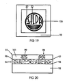
- Figure 19 is a plan view similar to Figure 18 but viewed at a different angle of incidence which makes visible the "SICPA" symbol incorporated in the paired optically variable device.
- Figure 20 is a cross-sectional view taken along the line 20-20 in Figure 19.
- Figure 21 is a plan view of a paired optically variable device incorporated into dot matrix foils with a symbol incorporated therein and having an angle of incidence in which the symbol is invisible.
- Figure 22 is a view similar to Figure 21 with a different angle of incidence so that the symbol incorporated therein is visible.
- Figure 23 is a cross-sectional view taken along the line 23-23 of Figure 22.
- In general, the optically variable device of the present invention is for use or viewing under incident light and is comprised of a substrate having first and second surfaces. First and second optical devices are carried by the first surface of the substrate in first and second spaced apart portions on the first surface to permit viewing at the same time by a human eye. A first optically variable pigment is disposed in the first optical device and a second optical pigment is disposed in the second device. The first and second optical devices have substantially the same color at one angle of incidence and colors different from each other at all other angles of incidence.
- More in particular as shown in Figure 1 of the drawings, the optically
variable device 11 consists of asubstrate 12 provided with first andupper surface 13 and a second orlower surface 14 as shown in Figure 2. Thesubstrate 12 can be flexible or rigid and can be formed of any suitable material such as paper, plastic, cardboard, metal and the like. Thesubstrate 12 can be opaque or transparent. Paired opticallyvariable pigments 16 in a polymeric binder are disposed on one of the surfaces as for example on the first ortop surface 13 as shown in Figure 2 so that they are not superposed but are lying in spaces which are physically separated from each other on the plane of thesurface 13. When the optically variable device is viewed the paired opticallyvariable pigments 16 can be viewed simultaneously. - Thus as shown in Figure 1, the
device 11 has paired opticallyvariable pigments 16 provided in a first optically variable device orpattern 17 and also in a second optically variable device orpattern 18. The first andsecond patterns first pattern 17 is in the form of a rectangle or square and is disposed within arecess 19 formed by thesecond pattern 18 also being in the form of a rectangle or square to form a border or frame that surrounds thefirst pattern 17. - The first optically
variable device 17 or thefirst pattern 17 is provided with a first pigment formed of optically variable flakes 2i constructed in the manner hereinbefore described to provide a first color shift with angle. The second optically variable device orsecond pattern 18 is provided with a second pigment formed of opticallyvariable flakes 22 also constructed in the manner hereinafter described and providing a second color shift with angle. As shown in Figure 2, thepigments liquid vehicles variable devices - In the first and second pigments or
flakes pigments variable pigments pigments device 11 shown in Figure 1, thepigments first device 17 and the color blue for thesecond device 18. Thus, it can be seen there is a dramatic color shift differential when shifting from 10° to 45° the angle of incidence of the paired opticallyvariable device 11. - In one embodiment of the invention as shown in Figure 1, the inner first optically variable device (OVD) 17 had the following characteristics with respect to the outer or second optically variable device (OVD) 18.
OUTER OVD 18INNER OVD 17 L* 54.91 L* 42.69 a* -32.45 a* 19.29 b* -11.48 b* -51.25 - The a* and b* used above are used in connection with a recognized standard color space system. In the color space system, the colors are plotted in a plane of the CIELAB-system in which a* represents red and green and b* represents yellow and blue. The lightness of the color is on an axis at right angles to the plane going from black or L* = 0 to white where L* = 100. Thus the color would be grey in the center of the plane with the chroma increasing from the center toward the outer perimeter of the plane. The extreme edge of the plane defines the highest chroma. For example, a red light emitting laser would have high chroma. Between the center and edge, there are various gradations of the red as for example, a pink. Thus, there are planes of these colors which move up and down the L* axis or the lightness value axis. For every illuminant-observer combination of the tristimulus value, the color coordinates can be readily calculated and also can be measured. It is well known to those skilled in the art of color, that any pigment or any color can have a different appearance depending upon the illuminant. For example a color under fluorescent light may be quite different from the color under sunlight or under a tungsten lamp. In accordance with the present invention, it is important that the matched colors of the
pigments 


- In connection with the present invention, the L*, a*, b* (CIELAB) color space is used to describe the invention since this system is the most uniform (linear in color) known to date and is generally accepted worldwide for practical use. Thus, in the CIELAB color space, the color of any optically variable device can be characterized by the three tristimulus values, X, Y and Z. These tristimulus values take into account the spectral distribution of the light source, the reflectance of the optically variable pigment and the spectral sensitivity to the human eye. It is from these X, Y and Z values that the L*, a*, b* coordinates are calculated as are the related values of L* (lightness), C* (chroma), h (hue) and associated color differences i.e. delta L*, delta C* and delta h. The appropriate color formulae are listed below.


- The designs for the paired optically variable pigments are selected so that in the a* b* diagrams of the same there are crossover points at which the optically variable pigments will have the same hue and chroma. The manner in which these colors of the optically variable pigments change with angle is dependent upon the ambient lighting conditions. Thus in connection with the present invention, three different types of illumination are considered. Illuminant A represents illumination from an incandescent (tungsten) light at a temperature of 2856° Kelvin. Illuminant C represents average sunlight with a correlated color temperature of 6770° Kelvin and Illuminant F represents light from a cool white fluorescent source at a correlated color temperature of 4200° Kelvin. These three illuminants have been chosen because they represent the most common forms of illumination for both interior and exterior lighting conditions.
- In Tables I to VI below and in the drawings in Figures 3-6 there are shown representative samples of designs which are possible under illuminant A. Thus for example in Table I, there are shown ten examples of paired optically variable pigments. Selecting Example 1 in Table I, Design 1 has a thin film interference stack of two quarter waves at the 620 nanometers and for
Design 2 four quarter waves at 587 nanometers. For Design 1 andDesign 2 in this example, the color is almost the same at 10° viewing orientation.TABLE I PAIRED OPTICALLY VARIABLE PIGMENTS ILLUMINANT A AT 10° Example Design 1 Design 21) 2 qw @ 620nm and 4 qw @ 587nm 2) 2 qw @ 691nm " 4 qw @ 593nm 3) 3 qw @ 697nm " 5 qw @ 649nm 4) 2 qw @ 510nm " 5 qw @ 671nm 5) 2 qw @ 478nm " 6 qw @ 674nm 6) 3 qw @ 498nm " 6 qw @ 589nm 7) 3 qw @ 653nm " 5 qw @ 595nm 8) 3 qw @ 506nm " 6 qw @ 642nm 9) 2 qw @ 420nm " 5 qw @ 577nm 10) 3 qw @ 534nm " 4 qw @ 688nm - Table II set forth below shows the calculated color values of L*, a*, b*, h and C* for each pair in the Example 1-10 consisting of Design 1 and
Design 2. Example 1 at 10°, of the pair of optical variable pigments has an L* value of 77.85 andDesign 2 has an L* value of 79.76. With the angle shifted to 45°, Design 1 has an L* value of 91.89 andDesign 2 has an L* value of 76.77. In addition, Table II shows the calculated color parameters for the designs shown in Table I.TABLE II COLOR VALUES FOR EXAMPLES IN TABLE I Example L* a* b* h C* Delta h 1) a, 10 deg. 77.85 29.7 62.92 64.73 69.58 a, 45 deg. 91.89 -1.91 39.76 92.75 39.81 b, 10 deg. 79.76 29.84 63.08 64.68 69.78 0.05 b, 45 deg. 76.77 -62.02 18.75 163.18 64.79 2) a, 10 deg. 58.53 36.17 53.01 55.69 64.17 a, 45 deg. 83.1 23.44 55.06 66.94 59.84 b, 10 deg. 78.03 35.82 53.9 56.39 64.72 -0.7 b, 45 deg. 78.58 -58.41 26.6 155.51 64.18 3) a, 10 deg. 81.33 -52.1 43.3 140.27 67.74 a. 45 deg. 49.72 -30.43 -66.53 245.42 73.16 b, 10 deg. 75.85 -52.49 44.06 139.99 68.53 0.28 b, 45 deg. 48.94 9.95 -53.89 280.46 54.8 4) a, 10 deg. 92.04 -15.83 27.36 120.05 31.61 a, 45 deg. 78.01 -30.76 -24.94 219.04 39.6 b, 10 deg. 77.84 -15.65 27.6 119.56 31.72 0.49 b, 45 deg. 53.19 -35.35 -33.02 223.05 48.37 5) a, 10 deg. 87.69 -28.3 4 171.96 28.58 a, 45 deg. 68.76 -25.8 -43.28 239.2 50.39 b, 10 deg. 58.53 -29.83 4.4 171.61 30.15 0.35 b, 45 deg. 75.5 27.99 -0.05 359.91 27.99 6) a, 10 deg. 44.24 37.16 -4.47 353.15 37.43 a, 45 deg. 71.36 31.84 56.4 60.55 64.77 b, 10 deg. 73.84 37.62 -5.69 351.39 38.05 1.76 b, 45 deg. 65.35 -78.45 15.06 169.13 79.88 7) a, 10deg. 68.32 -71.62 -11.06 188.78 72.46 a, 45 deg. 39.55 13.83 -79.77 279.84 80.96 b, 10 deg. 57.19 -71.73 -11.56 189.16 72.66 -0.38 b, 45 deg. 60.07 57.93 -31.07 331.79 65.73 8) a, 10 deg. 41.61 37.4 -19.15 332.89 42.02 a, 45 deg. 68.68 32.58 55.37 59.53 64.24 b, 10 deg. 57.74 38.71 -18.47 334.49 42.89 -1.6 b, 45 deg. 77.91 -21.93 29.77 126.39 36.97 9) a, 10 deg. 70.53 -28.52 -41.34 235.4 50.22 a, 45 deg. 51.31 -12.96 -53.61 256.41 55.15 b, 10 deg. 49.98 -30.65 -40.7 233.02 50.95 2.38 b, 45 deg. 67.43 54.11 -2.19 357.68 54.15 10) a, 10 deg. 35.03 35.58 -63.93 299.1 73.16 a, 45 deg. 59.41 33.45 43.83 52.65 55.13 b, 10 deg. 46.5 34.99 -63.1 299.01 72.15 0.09 b, 45 deg. 77.49 36.42 46.37 51.85 58.96 - The color difference at 10° viewing angle as well as that for a 45° viewing angle for each example is set forth below in Table III. The total color difference delta E (ΔE) between the colors of the paired optically variable pigments are calculated from L*, a*, and b* using Formula 6:

TABLE III TOTAL COLOR DIFFERENCE (DELTA E) FOR EXAMPLES IN TABLE I Pair Total Color Difference (Delta E) Des. Pair Example 10 Deg. 45 Deg. 1 1.92 65.45 2 19.52 86.77 3 5.55 42.32 4 14.20 26.50 5 29.20 69.34 6 29.63 117.94 7 11.14 68.83 8 16.20 60.93 9 20.67 86.04 10 11.52 18.50 Design pairs are from the 10 degree designs. Note: The 45° data shows the color difference at 45° for the 10 degree color pairs. - Thus the lower the ΔE value, the closer the colors match. ΔE includes not only hue and color saturation but the brightness of the paired optically variable pigments as well.
- Figures 3 and 4 of the drawings are graphical representations of what has been presented in Tables I, II, and III. Figure 3 shows how closely the colors are matched in hue and chroma for the examples of the paired designs of the paired optically variable pigments in the a*b* color space. From Figure 3 it can be seen that the pairs are of almost identical colors at the 10° orientation. However, when the pairs are tilted to 45° the two designs of each color pair and each of the examples have widely different color properties which is what is desired in accordance with the present invention. Thus there have been provided ten examples of paired optically variable pigments. Each have essentially no hue and chroma difference at 10° but at 45° have widely divergent hue and chroma contrasts. In the graphs in Figure 3 and 4, the paired designs are identified in accordance with Tables I, II and III. Thus Example 1 with design 1 is labeled "1-1" and Example 1 with
design 2 is labeled "1-2". - In Tables IV, V and VI below there are set forth eight examples of paired designs for paired optically variable pigments in accordance with the present invention in which the converse of that obtained in the ten examples in Tables I, II and III has been given in which color differences are minimized at 45° and color changes occur at a shifted angle, as for example at 10°.
TABLE IV PAIRED OPTICALLY VARIABLE PIGMENTS ILLUMINANT "A" AT 45° Example Design 1 Design 21) 3 qw @ 480nm and 4 qw @ 679nm 2) 3 qw @ 520nm " 4 qw @ 684nm 3) 4 qw @ 604nm " 6 qw @ 625nm 4) 2 qw @ 589nm " 6 qw @ 646nm 5) 3 qw @ 576nm " 6 qw @ 678nm 6) 4 qw @ 568nm " 5 qw @ 690nm 7) 2 qw @ 491nm " 5 qw @ 668nm 8) 3 qw @ 618nm " 5 qw @ 637nm COLOR VALUES FOR EXAMPLES IN TABLE IV Example L* a* b* h C* Delta h1 1) a, 10 deg. 50.82 36.66 27.48 36.85 45.82 a, 45 deg. 77.26 28.97 56.77 62.96 63.73 b, 10 deg. 47.7 46.3 -62.59 306.49 77.85 b, 45 deg. 79.69 29.26 57.38 62.98 64.41 -0.02 2) a, 10 deg. 37.69 37.4 -43.45 310.72 57.33 a, 45 deg. 64 33.27 51.52 57.14 61.33 b, 10 deg. 46.92 40.45 -63.25 302.6 75.07 b, 45 deg. 78.5 33.36 51.52 57.08 61.37 0.06 3) a, 10 deg. 74.39 45.24 34.56 37.38 56.93 a, 45 deg. 81.34 -49.76 40.03 141.19 63.86 b, 10 deg. 62.14 55.64 -23.07 337.48 60.24 b, 45 deg. 76.13 -49.57 40.76 140.57 64.17 0.62 4) a, 10 deg. 85.13 21.38 58.48 69.91 62.27 a, 45 deg. 91.67 -15.3 25.98 120.49 30.15 b, 10 deg. 57.13 32.12 -16.24 333.18 35.99 b, 45 deg. 78.01 -15.16 26.14 120.11 30.22 0.38 5) a, 10 deg. 38.07 2.39 -86.75 271.58 86.78 a, 45 deg. 46.99 33.03 -4.13 352.87 33.29 b, 10 deg. 59.37 -38.13 6.59 170.2 38.7 b, 45 deg. 74.75 32.92 -3.34 354.2 33.09 -1.33 6) a, 10 deg. 83.74 7.45 79.7 84.66 80.04 a, 45 deg. 69.8 -66.9 -7.77 186.62 67.35 b, 10 deg. 76.72 15.34 8.92 30.18 17.74 b, 45 deg. 59.47 -66.82 -7.71 186.59 67.26 0.03 7) a, 10 deg. 89.99 -24.07 14.12 149.61 27.9 a, 45 deg. 72.65 -28.4 -36.59 232.19 46.31 b, 10 deg. 77.78 -20.8 30.47 124.32 36.89 b, 45 deg. 52.36 -29.21 -36.58 231.39 46.81 0.8 8) a, 10 deg. 53.77 -52.94 -55.48 226.34 76.69 a, 45 deg. 39.14 30.35 -58.22 297.53 65.65 b, 10 deg. 73.21 -69.53 44.19 147.56 82.38 b, 45 deg. 48.88 30.35 -58.63 297.37 66.02 0.16 1Delta h is calculated between the "a" and "b" pair at 45° incidence. TABLE VI TOTAL COLOR DIFFERENCE (DELTA E) FOR EXAMPLES IN TABLE IV Des. Pair ΔE ΔE 10 Deg. 45 Deg. 1 90.64 2.52 2 22.06 14.50 3 59.83 5.26 4 80.51 13.66 5 103.96 27.77 6 71.56 10.33 7 20.67 20.31 8 102.89 9.75 Design pairs are from the 45 degree designs. Note: The 10° data shows color difference for the 45 degree pairs at 10°. - Graphical representations of the data shown in Tables IV, V and VI are shown in Figures 5 and 6 of the drawings in which Figure 5 shows the color divergence at the 10° with illuminant A and Figure 6 shows no color divergence at an angle of 45° with illuminant A.
- Tables VII, VIII and IX below have the same data as Tables I, II and III except for illuminant C and with Figures 7 and 8 giving graphical representations showing the matching of colors at 10° and a divergence of the colors at 45°.
TABLE VII PAIRED OPTICALLY VARIABLE PIGMENTS ILLUMINANT "C" AT 10° Example Design 1 Design 21) 2 qw @ 625nm and 4 qw @ 582nm 2) 2 qw @ 683nm " 4 qw @ 586nm 3) 3 qw @ 692nm " 5 qw @ 641nm 4) 2 qw @ 509nm " 5 qw @ 662nm 5) 2 qw @ 475nm " 6 qw @ 663nm 6) 3 qw @ 644nm " 5 qw @ 586nm 7) 3 qw @ 495nm " 5 qw @ 698nm 8) 3 qw @ 501nm " 6 qw @ 630nm 9) 2 qw @ 410nm " 5 qw @ 567nm 10) 3 qw @ 528nm " 4 qw @ 674nm TABLE VIII COLOR VALUES FOR EXAMPLES IN TABLE VII L* a* b* h C* Delta E 1) a, 10 deg. 72.64 20.06 61.26 71.87 64.46 a, 45 deg. 90.38 -7.77 42.78 100.29 43.48 b, 10 deg. 76.96 20.89 60.38 70.91 63.9 0.96 b, 45 deg. 78.94 -67.69 24.79 159.88 72.08 2) a, 10 deg. 56.51 27.2 52.22 62.49 58.88 a, 45 deg. 81.46 11.68 52.49 77.45 53.78 b, 10 deg. 75.65 26.22 53.5 63.89 59.58 -1.4 b, 45 deg. 79.98 -66.71 29.87 155.88 73.09 3) a, 10 deg. 82.81 -62.64 49.66 141.59 79.94 a, 45 deg. 54.05 2.14 -59.72 272.05 59.76 b, 10 deg. 76.65 -63.43 50.66 141.39 81.18 0.2 b, 45 deg. 50.87 28.79 -52.27 298.85 59.67 4) a, 10 deg. 92.3 -22.4 30.75 126.07 38.05 a, 45 deg. 80.93 -22.21 -19.14 220.75 29.32 b, 10 deg. 77.62 -21.83 30.05 126 37.14 0.07 b, 45 deg. 55.54 -22.03 -30.15 233.85 37.34 5) a, 10 deg. 89.1 -29.92 7.74 165.49 30.9 a, 45 deg. 71.49 -6.53 -39.38 260.58 39.92 b, 10 deg. 59.27 -30.64 8.59 164.34 31.82 1.15 b, 45 deg. 74.52 27.69 -1.75 356.39 27.75 6) a, 10 deg. 70.39 -64.05 -8.22 187.31 64.58 a, 45 deg. 41.49 56.46 -77.43 306.1 95.83 b, 10 deg. 59.12 -62.93 -9.48 188.57 63.64 -1.26 b, 45 deg. 58.86 71.26 -33.23 335 78.63 7) a, 10 deg. 41.84 41.97 -10.45 346.02 43.25 a, 45 deg. 68.52 21.46 53.63 68.2 57.77 b, 10 deg. 72.02 43.2 -11.02 345.69 44.59 0.33 b, 45 deg. 67.3 -83.81 20.31 166.38 86.24 8) a, 10 deg. 40.08 46.15 -21.57 334.95 50.95 a, 45 deg. 66.48 22.23 52.91 67.21 57.39 b, 10 deg. 58.15 46.02 -22.39 334.05 51.17 0.9 b, 45 deg. 77.88 -35.97 36.76 134.38 51.43 9) a, 10 deg. 70.7 -5.86 -41.68 261.99 42.09 a, 45 deg. 51.51 16.22 -50.64 287.76 53.18 b, 10 deg. 51.82 -6.18 -41.04 261.44 41.51 0.55 b, 45 deg. 66.24 55.65 -0.31 359.68 55.65 10) a, 10 deg. 35.28 65.89 -64.15 315.77 91.96 a, 45 deg. 57.52 25.14 42.43 59.35 49.32 b, 10 deg. 47.88 66.02 -64.13 315.83 92.04 -0.06 b, 45 deg. 76.79 21.61 53.51 68.01 57.71 TABLE IX Pair Total Color Difference (Delta E) For Examples in Table VII Des. Pair ΔE ΔE 10 Deg. 45. Deg. 1 4.49 63.60 2 19.21 81.60 3 6.29 27.85 4 14.71 27.67 5 29.85 50.95 6 11.40 49.74 7 30.21 110.42 8 18.09 61.47 9 18.89 65.61 10 12.60 22.51 Design pairs are from the 10° designs. Note: The 45° data shows color difference at 45° for the 10° color pairs. - In Tables X, XI and XII there are shown the designs corresponding to the designs shown in Tables IV, V and VI under illuminant C rather than illuminant A. Figures 9 and 10 represent graphically the information set forth in Tables X through XII and show the divergence in colors at 10° and the matching of colors at 45°.
TABLE X PAIRED OPTICALLY VARIABLE PIGMENTS ILLUMINANT "C" AT 45° 1) 3 qw @ 490nm and 4 qw @ 673nm 2) 4 qw @ 600nm " 6 qw @ 617nm 3) 2 qw @ 587nm " 6 qw @ 637nm 4) 4 qw @ 560nm " 5 qw @ 680nm 5) 3 qw @ 571nm " 6 qw @ 668nm 6) 2 qw @ 482nm " 5 qw @ 657nm 7) 2 qw @ 395nm " 5 qw @ 646nm 8) 3 qw @ 612nm " 5 qw @ 625nm TABLE XI COLOR VALUES FOR EXAMPLES IN TABLE X L* a* b* h C* Delta h 1) a, 10 deg. 43.43 38.9 -1.07 358.4 38.91 a, 45 deg. 70.12 20.71 53.98 69.01 57.82 b, 10 deg. 47.94 67.28 -64.17 316.4 92.98 b, 45 deg. 77.06 20.51 54.79 69.48 58.5 -0.47 2) a, 10 deg. 70.59 43.92 26.21 30.82 51.15 a, 45 deg. 82.82 -59.26 46.22 142.1 75.15 b, 10 deg. 60.93 61.29 -27.55 335.8 67.19 b, 45 deg. 76.86 -60.25 46.8 142.2 76.29 -0.11 3) a, 10 deg. 82.42 10.57 56.87 79.47 57.85 a, 45 deg. 91.91 -21.75 28.77 127.1 36.06 b, 10 deg. 57.36 32.99 -17.27 332.4 37.23 b, 45 deg. 77.83 -21.76 28.84 127 36.13 0.05 4) a, 10 deg. 82.62 -10.03 81.72 97 82.34 a, 45 deg. 71.62 -61.4 -5.38 185 61.64 b, 10 deg. 75.75 14.17 7.59 28.19 16.07 b. 45 deg. 61.33 -61.68 -5.15 184.8 61.9 0.24 5) a, 10 deg. 41.84 48.94 -82.46 300.7 95.89 a, 45 deg. 45.27 36.34 -7.16 348.9 37.04 b, 10 deg. 60.34 -41.51 12.6 163.1 43.38 b, 45 deg. 73.45 35.39 -6.69 349.3 36.02 -0.45 6) a, 10 deg. 90.18 -29.4 13.02 156.1 32.15 a, 45 deg. 73.57 -10.13 -35.74 254.2 37.15 b, 10 deg. 77.72 -32.2 36.15 131.7 48.42 b, 45 deg. 54.15 -9.56 -36.36 255.3 37.6 -1.1 7) a, 10 deg. 65.11 3.21 -49.13 273.7 49.24 a, 45 deg. 47.28 16.19 -47.11 289 49.82 b, 10 deg. 77.22 -54.22 47.36 138.9 71.99 b, 45 deg. 51.67 17.42 -48.07 289.9 51.13 -0.95 8) a, 10 deg. 57.8 -21.96 -48.94 245.8 53.64 a, 45 deg. 39.33 57.93 -59.39 314.3 82.97 b, 10 deg. 73.45 -86.61 49.34 150.3 99.68 b, 45 deg. 50.08 57.92 -59.69 314.1 83.17 0.15 TABLE XII Pair Total Color Difference (Delta E) For Examples in Table X Design Pair ΔE ΔE 10° 45° 1 69.34 6.99 2 57.32 6.07 3 81.41 14.08 4 78.28 10.30 5 132.51 28.20 6 26.42 19.44 7 112.94 4.66 8 118.67 10.75 Design pairs are from the 45° designs. Note: The 10° data shows color difference for the 45° color pairs. - In Tables XIII, XIV and XV set forth below designs are shown corresponding to the designs in Tables I through III except for illuminant F rather than illuminant A and graphical representations of the data presented therein are shown in Figures 11 and 12 in which Figure 11 shows the matching of colors at 10° and Figure 12 showing the divergence of colors at 45°.
TABLE XIII PAIRED OPTICALLY VARIABLE PIGMENTS ILLUMINANT "F" AT 10° 1) 2 qw @ 640nm and 4 qw @ 582nm 2) 3 qw @ 689nm " 5 qw @ 644nm 3) 2 qw @ 499nm " 5 qw @ 663nm 4) 3 qw @ 656nm " 6 qw @ 684nm 5) 2 qw @ 466nm " 6 qw @ 664nm 6) 3 qw @ 490nm " 5 qw @ 694nm 7) 3qw@ 647nm " 6 qw @ 704nm 8) 3 qw @ 497nm " 6 qw @ 637nm 9) 4 qw @ 620nm " 6 qw @ 605nm 10) 3 qw @ 637nm " 5 qw @ 583nm 11) 2 qw @ 405nm " 4 qw @ 708nm 12) 3 qw @ 525nm " 4 qw @ 677nm TABLE XIV COLOR VALUES FOR EXAMPLES IN TABLE XIII L* a* b* h C* Delta h 1) a, 10 deg. 70.42 17.33 68.25 75.75 70.42 a, 45 deg. 91.01 -0.06 52.65 90.03 52.35 b, 10 deg. 81.78 18.02 66.68 74.88 69.07 0.87 b, 45 deg. 76.56 -50.36 24.67 153.9 56.08 2) a, 10 deg. 82.02 -47.88 50.35 133.56 69.48 a, 45 deg. 47.02 3.11 -70.45 272.53 70.52 b, 10 deg. 78.72 -48.35 50.78 133.59 70.12 -0.03 b, 45 deg. 44.8 17.49 -56.3 287.26 58.96 3) a, 10 deg. 92.38 -18.21 27.65 123.37 33.11 a, 45 deg. 75.84 -14.15 -29 243.98 32.26 b, 10 deg. 82.31 -17.81 27.35 123.08 32.64 0.29 b, 45 deg. 47.84 -18.63 -36.81 243.15 41.25 4) a, 10 deg. 70.22 -52.74 4.55 175.07 52.93 a, 45 deg. 39.29 36.13 -87.28 292.48 94.46 b, 10 deg. 56.94 -53.73 5.39 174.27 54 0.8 b, 45 deg. 74.02 41.47 -11.9 343.98 43.14 5) a, 10 deg. 86.1 -21.62 0.36 179.06 21.62 a, 45 deg. 65.94 -2.79 -48.83 266.73 48.91 b, 10 deg. 50.31 -24.08 1.4 176.68 24.12 2.38 b, 45 deg. 80.28 22.17 -1.29 356.67 22.21 6) a, 10 deg. 44.03 27.44 -3.71 352.3 27.69 a, 45 deg. 72.06 16.14 59.42 74.8 61.57 b, 10 deg. 79.12 28.38 -4.28 351.43 28.7 0.87 b, 45 deg. 59.34 -62.69 9.29 171.57 63.37 7) a, 10 deg. 66.41 -49.94 -8.6 189.77 50.67 a, 45 deg. 38.08 41.75 -87.76 295.44 97.18 b, 10 deg. 66.48 -49.32 -7.89 189.09 49.95 0.68 b, 45 deg. 65.69 48.61 -19.05 338.6 52.21 8) a, 10 deg. 41.58 30.62 -17.96 329.62 35.5 a, 45 deg. 69.56 16.73 58.62 74.07 60.96 b, 10 deg. 52.11 32.22 -18.3 330.4 37.06 -0.78 b, 45 deg. 82.18 -19.46 27.98 124.82 34.08 9) a, 10 deg. 65.12 50.15 -18.32 339.93 53.4 a, 45 deg. 87.08 -29.95 72.63 112.41 78.57 b, 10 deg. 67.08 50.75 -18.6 339.88 54.05 0.05 b, 45 deg. 73.08 -62.1 47.61 142.52 78.25 10) a, 10 deg. 62.04 -44.38 -23.12 207.52 50.04 a, 45 deg. 37.3 45.43 -85.71 297.93 97 b, 10 deg. 49.09 -44.37 -23.42 207.83 50.17 -0.31 b, 45 deg. 61.23 52.61 -34.86 326.47 63.11 11) a, 10 deg. 65.91 -3.46 -49.97 266.03 50.09 a, 45 deg. 48.12 10.55 -55.9 280.68 56.89 b, 10 deg. 43.12 -3.06 -50.61 266.54 50.7 -0.51 b, 45 deg. 68.5 43.66 -6.27 351.83 44.11 12) a, 10 deg. 34.16 48.14 .69 304.9 84.13 a, 45 deg. 59.75 18.29 47.59 68.98 50.98 b, 10 deg. 42.9 47.78 -69.2 304.62 84.09 0.28 b, 45 deg. 80.42 20.93 54.69 69.06 58.55 TABLE XV TOTAL COLOR DIFFERENCE (DELTA E) FOR EXAMPLES IN TABLE XIII Pair Total Color Difference (Delta E) Des. Pair III. F Delta E 10 Deg. 45 Deg. 1 11.49 59.34 2 3.36 20.30 3 37.40 29.41 4 13.34 83.17 5 35.89 55.58 6 35.11 94.28 7 0.95 74.37 8 10.66 49.07 9 2.07 43.08 10 12.95 56.66 11 22.80 63.05 12 8.75 22.01 Design pairs are from the 10° designs. Note: The 45° data shows color difference at 45° for the 10° color pairs. - In Tables XVI, XVII and XVIII set forth below, data are shown corresponding to the designs in Tables IV through VI except with illuminant F rather than illuminant A Graphical representations of these designs are shown in Figure 13 and 14 in which Figure 13 shows a divergence in colors at 10° and Figure 14 shows the matching of colors at 45°.
TABLE XVI PAIRED OPTICALLY VARIABLE PIGMENTS ILLUMINANT F AT 45° 1) 4 qw @ 597nm and 6 qw @ 621nm 2) 2 qw @ 576nm " 6 qw @ 638nm 3) 3 qw @ 566nm " 6 qw @ 666nm 4) 5 qw @ 573nm " 6 qw @ 698nm 5) 4 qw @ 555nm " 5 qw @ 677nm 6) 2 qw @ 475nm " 5 qw @ 656nm 7) 2 qw @ 394nm " 5 qw @ 648nm 8) 3 qw @ 608nm " 5 qw @ 627nm TABLE XVII COLOR VALUES FOR EXAMPLES IN TABLE XVI L* a* b* h C* Delta h 1) a, 10 deg. 75.86 31.97 33.73 46.54 46.47 a, 45 deg. 82 -45.7 46.24 134.66 65.02 b, 10 deg. 58.73 48.61 -21.89 335.75 53.31 b, 45 deg. 79.13 -44.8 46.61 133.86 64.65 0.8 2) a, 10 deg. 87.43 6.52 61.63 83.96 61.98 a, 45 deg. 91.97 -17.59 26.08 124 31.46 b, 10 deg. 51.8 30.69 -17.82 329.85 35.49 b, 45 deg. 82.27 -17.75 26.59 123.73 31.97 0.27 3) a, 10 deg. 35.02 43.33 -95.12 294.49 104.53 a, 45 deg. 47.02 24.04 -2.29 354.55 24.15 b, 10 deg. 50.72 -28.44 2.8 174.39 28.58 b, 45 deg. 79.81 24.6 -2.59 353.99 24.74 0.56 4) a, 10 deg. 45.06 -20.31 -40.84 243.56 45.61 a, 45 deg. 66.06 47.12 -16.88 340.29 50.05 b, 10 deg. 63.59 -52.86 -4.05 184.38 53.01 b, 45 deg. 68.27 47.87 -17.36 340.07 50.92 0.22 5) a, 10 deg. 87.84 -11.09 92.92 96.81 93.58 a, 45 deg. 64.39 -43.16 -17.6 202.18 46.61 b, 10 deg. 82.22 5.43 9.35 59.86 10.81 b, 45 deg. 52.37 -43.48 -17.16 201.54 46.75 0.64 6) a, 10 deg. 88.27 -21.64 8.33 158.96 23.19 a, 45 deg. 68.69 -6.07 -44.24 262.19 44.66 b, 10 deg. 81.49 -29.72 37.27 128.57 47.67 b, 45 deg. 46.21 -4.92 -45.15 263.78 45.42 -1.59 7) a, 10 deg. 61.81 1.24 -55.67 271.27 55.68 a, 45 deg. 45.3 10.27 -52.64 281.04 53.64 b, 10 deg. 79.83 -42.51 47.11 132.06 63.46 b, 45 deg. 45.01 10.35 -53.08 281.04 54.08 0 8) a, 10 deg. 49.35 -13.76 -62.12 257.51 63.62 a, 45 deg. 38.39 41.5 -63.37 303.22 75.75 b, 10 deg. 72.05 -67.21 51.64 142.46 84.75 b, 45 deg. 45.64 41.56 -63.88 303.04 76.21 0.18 TABLE XVIII TOTAL COLOR DIFFERENCE (DELTA E) FOR EXAMPLES IN TABLE XVI Pair Total Color Difference (Delta E) Des. Pair ΔE ΔE 10 Deg. 45 Deg. 1 60.53 3.03 2 90.37 9.71 3 122.42 32.80 4 52.50 2.38 5 85.37 12.03 6 30.80 22.53 7 113.15 0.53 8 127.72 7.27 Design pairs are from the 45° designs. Note: The 10° data shows color difference at 10° for the 45° color pairs. - In viewing the data set forth in the foregoing tables, it can be seen that there is a color difference for different types of illumination. In other words, under one illuminant there may be an exact color match whereas under another illuminant there may no longer be an exact color match. Thus there is a color change which traditionally is known as color metamerism. In viewing Table III, example 1 gives the lowest color difference of 1.92 whereas example 6 gives the highest color difference of 29.63 for designs for matching colors at 10°. Table VI for matching colors at 45°, the minimum color difference is 2.52 for example 1 and the maximum color difference is 27.77 for example 5. Similar analyses can be carried out for Tables IX, XII, XV and XVIII, to give a minimum of 4.49 and a maximum 30.21 for Table IX, a minimum of 4.66 and a maximum 28.2 for Table XII, a minimum 0.95 and a maximum of 37.4 for Table XV and a minimum of 0.53 and a maximum of 32.8 for Table XVIII.
- Similarly, the data in Tables I through XVIII can be analyzed to ascertain the paired designs under the illuminants A, C and F as set forth below in Table XIX.
TABLE XIX TOTAL COLOR DIFFERENCE FOR PAIRED OPTICALLY VARIABLE PIGMENTS FROM DIELECTRIC THICKNESS TRACKS UNDER ILLUMINANTS "A", "C" AND "F" Pair Ill. Angle Delta E Designs 1 and 2 1 A 10 1.92 2 qw @ 620 & 4 qw @ 587 3 A 10 5.55 3 qw @ 697 & 5 qw @ 649 1 A 45 2.52 3 qw @ 480 & 4 qw @ 679 3 A 45 5.26 4 qw @ 604 & 6 qw @ 625 1 C 10 4.49 2 qw @ 625 & 4 qw @ 582 3 C 10 6.29 3 qw @ 692 & 5 qw @ 641 7 C 45 4.66 2 qw @ 395 & 5 qw @ 646 2 C 45 6.99 4 qw @ 600 & 6 qw @ 617 7 F 10 0.95 3 qw @ 647 & 6 qw @ 704 9 F 10 2.07 4 qw @ 620 & 6 qw @ 605 7 F 45 0.53 2 qw @ 394 & 5 qw @ 648 4 F 45 2.38 5 qw @ 573 & 6 qw @ 698 - As can be seen in Table XIX above, the best two design pairs for each illuminant and at each angle have been selected. For example, two design pairs at a 10° viewing angle under Illuminant A were shown to have the lowest color mismatch. Similarly, two different paired designs had the best color match at a 45° viewing angle under Illuminant A. Those which have been selected are the ones which have the smallest color difference for the chosen angle. Similarly, the examples have been selected for the best two color matched pairs under Illuminant C and similarly for Illuminant F under the two different orientations. Using this criteria the best overall design pair was found under Illuminant F at 45°. By reviewing Table XIX, the color difference for the pair: 2 qw at 394 nanometers and 5 qw at 648 nanometers has a ΔE at 0.53.
- In Table XX set forth below, the two design pairs selected in Table XIX were analyzed to ascertain whether or not a color match still existed under different illuminants. When those designs are forced under Illuminant A, the color difference in terms of ΔE is now 36.44 and when it is placed under Illuminant C it has a value of only 6.15. Thus it can be seen that when the best pair of optically variable pigments under Illuminant F is placed under a different illumination the color match is no longer an exact color match. Other paired designs were also viewed under different illuminants to see the effect in their ΔE color difference and this data has been tabulated in Table XX.
TABLE XX Best 2 Under Ill. A, C & F Pair Code(*) L* a* b* hue C' Delta E 10 Deg. III. A Design (known) under e C 1 4C1 74 19.13 60.87 72.55 63.8 12.52 4C2 75.31 27.54 51.69 61.95 58.56 2 4C1 83.46 -59.1 54.67 137.23 80.51 15.77 4C2 77.45 -48.41 44.75 137.25 65.92 45 Deg. III. A Design (known) under C 1 4C1 73.58 18.87 54.16 70.79 57.35 11.19 4C2 75.42 27.01 46.7 59.96 53.94 2 4C1 83.39 -56.17 50.41 138.09 75.48 14.80 4C2 77.66 -45.77 41.57 137.76 61.83 Pair Code(*) L* a' b* hue C' Delta E 10 Deg. III. A Design (known) under F 1 7F1 76.2 15.29 67.44 77.22 69.15 13.84 7F2 79.96 22.85 56.47 67.97 60.92 2 7F1 84.08 -43.8 60.17 126.05 74.43 14.95 7F2 80.08 -40.99 46.04 131.68 61.64 45 Deg. III. A Design (known) under F 1 7F1 75.6 15 59.87 75.93 61.72 12.08 7F2 79.79 22.48 51.36 66.37 56.06 2 7F1 84.01 -41.84 55.32 127.1 69.37 13.13 7F2 80.19 -39 43.08 132.16 58.11 Pair Code(*) L* a* b* hue C' Delta E 10 Deg. III. C Design (known) under A 1 5A1 76.56 30.65 63.38 64.19 70.4 9.83 5A2 81.04 24.43 69.53 70.64 73.7 2 5A1 80.3 -56.04 37.75 146.03 67.57 12.63 5A2 74.21 -64.27 45.14 144.92 78.54 45 Deg. III. C. Design (known) under A 1 5A1 44.65 -9.94 -47.69 258.22 48.72 26.98 5A2 48.76 15.53 -55.58 285.61 57.71 2 5A1 80.42 -53.18 35.31 146.42 63.83 11.42 5A2 74.5 -60.78 41.44 145.71 73.57 10 Deg. III. C Design (known) under F 1 7F1 74.77 15.89 67.78 76.8 69.62 7.41 7F2 81.78 18.02 66.68 74.88 69.07 2 7F1 82.84 -46.46 54.11 130.65 71.32 7.93 7F2 77.77 -52.41 52.79 134.8 74.39 45 Deg. III. C Design (known) under F 1 7F1 45.55 10.33 -52.99 281.03 53.98 4.12 7F2 44.83 13.98 -54.75 284.32 56.51 2 7F1 82.9 -44.16 50.23 131.32 66.88 7.86 7F2 77.88 -50.07 48.97 135.64 70.03 Pair Code(*) L* a* b* hue C* Delta E 10 Deg. III. F Design (known) under A 1 5A1 65.98 -70.89 -18.99 195 73.39 28.11 5A2 65.84 -63.36 8.09 172.72 63.88 2 5A1 68.31 55.32 4.94 5.11 55.54 22.70 5A2 68.99 53.67 -17.69 341.76 56.52 45 Deg. III. F Design (known) under A 1 5A1 35.45 -7.52 -26.69 254.27 27.73 36.44 5A2 48.87 11.84 -54.49 282.26 55.76 2 5A1 76.53 -45.75 39.82 138.96 60.66 111.57 5A2 69.92 50.45 -16.31 342.09 53.02 10 Deg. III. F Design (known) under C 1 4C1 71.45 -66.19 -4.28 183.7 66.33 18.17 4C2 69.19 -54.17 9.16 170.41 54.94 2 4C1 62.73 65.58 -12.97 348.82 66.85 14.03 4C2 64.51 64.5 -26.84 337.41 69.86 45 Deg. III. F Design (known) under C 1 4C1 47 16.12 -46.81 289 49.51 6.15 4C2 52.05 12.67 -46.18 285.34 47.88 2 4C1 77.8 -40.92 39.28 136.17 56.72 121.10 4C2 65.7 60.89 -25.17 337.54 65.89 - In the event that the present invention is utilized for preparing optically variable pigments to be used with currency to prevent counterfeiting, it should be appreciated that bank-note exchange is most likely to take place under cool fluorescent lighting as typically found in banks and retail stores. It is therefore believed that design pairs should be utilized which have matching colors under such lighting as for example Illuminant F as set forth above. Utilizing such principles the best overall design pair would be one involving two quarter waves at 394 nanometers and five quarter waves at 648 nanometers.
- Although the design pair involving two quarterwaves at 394 nanometers and five quarterwaves at 648 nanometers is the best overall design pair, the design at 394 nanometers does not have much of an optical shift, as can be seen by referring to Figures 13 and 14. This design pair, labeled "7-1" and "7-2" does have a divergence of color at 10°, but the change in color for the two quarterwave design is small. Thus, a preferable design pair would be Pair 4, which has the designs five quarterwaves at 573 nanometers and six quarterwaves at 698 nm. Both of these designs have substantial color shift with angle. They are widely separated in color at 10° and have a fairly good color match at 45°.
- It can be seen by referring to Tables II, V, VIII, XI, XIV and XVII that the color match in terms of hue is, for all practical purposes, an exact match. The ΔE differences for the various design pairs as shown in Tables III, VI, IX, XII, XV and XVIII are a consequence of slight variations of brightness, L* and in chroma, C*. These color variations can be minimized by adding a black or neutral transparent pigment or nontransparent pigment to the design of the pair which has the highest chroma and brightness value. The addition is made until the brightness and chroma are matched to the lower chroma and brightness design of the pair. Thus, all design pairs can be optimized for color matching by the judicious additions of other color modifying materials.
- All the foregoing principles can be utilized in conjunction with the optically
variable device 11 shown in Figure 1 in which paired optically variable pigments utilizing those principles can be incorporated into the two different opticalvariable devices - To achieve high color saturation and to have large color travel as a function of viewing angle which is desired in connection with the present invention, interference type pigments are utilized. In such pigments, metal dielectric or all dielectric interference stacks are utilized.
- A typical metal dielectric
asymmetric interference stack 31 as shown in Figure 15 is formed as a sheet on asoluble release layer 32 deposited on aflexible web 33 serving as a substrate. The multilayer interferencethin film stack 31 can be removed by passing the web or substrate through a solvent bath. As thesoluble release layer 32 dissolves, the thin sheet ofinterference film 31 disintegrates into a multitude of flakes. Since the flakes have two planar surfaces, it is desirable to provide an optical design for the multilayer interference stack or film so that it is symmetric and presents the same design on each side. After collecting the flakes and washing them to free them of release material, a pigment is produced by grinding the flakes to a size ranging from 2 to 200 microns and preferably a size ranging from 2 to 20 microns by grinding or pulverizing without destroying the color characteristics of the flakes. The flakes should have an aspect ratio of at least 2 to 1 with respect to the surfaces of the flakes and the thicknesses of the flakes and preferably 10 to 1 in order to preserve the correct particle orientation when they are placed in the desired vehicle for an ink or a paint to maximize the brightness and color purity of the ink or paint. - Thus in accordance with the present invention it is desirable to utilize a symmetric
metal dielectric stack 31 as shown in Figure 15 which can be comprised of only three materials and five layers to produce a strongly dichroic optically variable pigment. It is comprised of asemi-opaque metal layer 36 which is formed on therelease coat 32 carried by theflexible web 33. Thelayer 36 is followed by adielectric layer 37, a thickmetal reflecting layer 38, another dielectric layer 39 and a final thinsemi-opaque metal layer 41. For the production of a hot stamping dichroic foil (i.e., an optically variable foil), only three layers are required. These three layers would consist of: 36, 37 and 38, as shown in Figure 15. In this form, thelayers release coat 32 and theflexible web 33 and attached by means of an adhesive to a counter surface, thelayer 36 faces the viewer. By way of example each of thethin metal layers dielectric layers 37 and 39 can be formed from a suitable dielectric material such as silicon dioxide to an optical thickness of a plurality of half waves at a particular design wavelength. Themetal reflecting layer 38 may be formed of a layer of aluminum formed to the thickness of approximately 80 nanometers to provide opacity and high reflection. Although a layer of reflecting metal of greater thickness can be utilized, it is believed that it is preferable to minimize the stress in this layer by providing a thin layer as well as to maintain the correct aspect ratio for the product when in the form of a pigment. - It should be appreciated that the materials mentioned are by way of example only and that other grey metals such as nickel and Inconel when n and k (n=real part of refractive index and k=imaginary part of the refractive index) have a high nk product can be utilized in place of chromium. Also in place of silicon dioxide having an index of refraction of 1.46 for the dielectric, other low index materials having an index of refraction of 1.65 or less such as magnesium fluoride having an index of 1.38 and aluminum oxide having an index of 1.65 can be utilized or even lower reflecting metals, such as chromium, nickel or palladium for example, can be used for lower reflecting pigments. In place of aluminum as the metal reflecting layer, the optical metals such as gold, copper and silver can be utilized.
- It also should be appreciated if desired, an asymmetric metal dielectric interference stack can be provided if that is desired. When such is the case, the
metal reflecting layer 37 can be formed directly onto the release layer followed by the dielectric layer 39 and the thin metalsemitransparent metal layer 41. It must be appreciated that such a three-layer design when removed from the web would produce an optically variable pigment with lower chroma than a five-layer symmetrical stack but would nevertheless have dichroic features, i.e., color shift with viewing angle, and could potentially be used to produce lower chroma pairs of pigments with a color match at one angle and no color match at any other angle. These pigments would be equivalent to those already described, except that they would have lower overall chroma so that the designs listed in Tables I, IV, VII, X, XIII and XVI would have chroma compression around the origin of the a*b* plot, but nevertheless would have essentially the same color hue match. - If desired an all dielectric interference stack can be provided where that is deemed appropriate where the additional layers typically required can be provided without undue expense. As is shown in Figure 16, an all
dielectric interference stack 51 can be provided on arelease coat 52 carried by a flexible web or substrate 53. Such a dielectric stack is comprised of alternate layers 54 and 56 with the low index layers being identified as L1 through L5 and having an index refraction of 1.35 to 1.65 and the high index layers being identified as H1 through H4 having a high index of refraction of 1.7 to 2.4 for a total of nine layers. A wide variety of low and high index materials can be utilized in such a multilayer stack. For example, zinc sulfide can be utilized with magnesium fluoride and titanium dioxide can be utilized with silicon dioxide. Other dielectric materials can also be used such as germanium, silicon, indium tin oxide, indium oxide and silicon monoxide. - The design of an all dielectric stack may be expressed as follows:

- For example, in connection with the foregoing it has been found that paired optically variable foils and/or pigments with the same matched colors at 0° and 45° for an all-dielectric design can be achieved in which chroma and hue match. One design consists of (1 QW ZrO2/ 1QW SiO2)3 /1 QW ZrO2 and an additional design: (1 QW ZrO2 /3 QW SiO2)3 1QW ZrO2 in which the thicknesses of the quarter wave ranged from 400 nanometers to 2500 nanometers. For the single quarter wave design there are three possible matched pairs at 0° two matched pairs at 45°. Conversely, analyzing chroma and hue variation for the design (1QW ZrO2/3QW SiO2)3/1 qw ZrO2 at 0° there are two color match pairs at 45° and there are four color match pairs achievable. Table XXI shows the dielectric pairs that have a color match at 0° or at 45°.
- In connection with the foregoing, it should be appreciated that merely increasing the number of pairs of the dielectric design does not make it possible to achieve the coincidence of color matching. However, by increasing the individual thicknesses of the layers, coincidence in color matching can be achieved.
TABLE XXI Dielectric Pairs That Match Hue and Chroma at Angle Design Angle Design Pair a* b* L* (ZrO2/SiO2)3 ZrO 20 Deg. 1 qw @ 495nm -43.8 -6.41 83.61 1 qw @ 1480nm -45.25 -5.56 57.96 1 qw @ 540nm -33.6 50.83 90.95 1 qw @ 1680nm 33.75 54.24 75.20 (ZrO2/SiO2)3ZrO2 45 Deg. 1 qw @ 610nm -26.63 57.32 88.97 1 qw @ 1860nm -26.7 55.05 73.70 1 qw @ 550nm -37.45 -1.47 83.25 1 qw @ 1630nm -39.42 -1.2 59.28 (ZrO2/3 SiO2)3 ZrO 20 Deg. 1 qw @ 590nm 16.18 44.19 78.33 1 qw @ 870 nm 18.2 42.68 61.57 1 qw @ 615nm 43.49 17.89 70.62 1 qw @ 940nm 44.46 16.09 46.57 (ZrO2/3 SiO2)3ZrO2 45 Deg. 1 qw @ 700nm 45.13 9.82 67.18 1 qw @ 1030nm. 45.68 7.98 48.90 - 1 qw @ 760nm 30.4 -20.84 55.39 1 qw @ 2220nm 31.32 -19.38 51.52 - Thus it can be seen that metal-dielectric as well as all dielectric interference thin films can be utilized in the optically variable pigments utilized herein to provide the paired optically variable pigments hereinbefore described.
- The optically variable pigments of the present invention are inherently light fast. This inherency is derived from the fact that the color that emanates from the pigment is due to an interference effect and is not based on any chromophore that can be bleached by ultraviolet light. All the materials used in the construction of the optically variable pigment do not have any color or any chromophore and are, in fact, colorless in themselves. For example, the metals aluminum and chromium are silver and grey and the dielectric magnesium fluoride is water-white transparent.
- In Figure 17, there is shown a pair of paired optically variable devices incorporating the present invention. On the left-hand side of Figure 17 there is shown a first or one paired optically
variable device 71 and on the right-hand side there is shown a second or another paired opticallyvariable device 72 with bothdevices device 71 has a centrally disposed first or inner opticallyvariable device 76 in the form of a circle seated within acircular hole 77 provided in the second or outer opticallyvariable device 78 in the form of a square or rectangle. Similarly, the second paired opticallyvariable device 72 consists of an inner or first opticallyvariable device 81 in the form of a circle which is disposed within ahole 82 provided in a second or outervariable device 83 in the form of a rectangle or square. The twodevices device 76 in the form of the circle indevice 71 and thedevice 83 in the form of a rectangle carry the same optically variable pigment and similarly, thedevice 78 and thedevice 81 of thedevice 71 and thedevice 72 respectively carry the same optically variable pigment. - Thus by way of example as shown below, the pigment carried by the
devices devices devices devices devices device 71 having a magenta center and a blue border and conversely thedevice 72 will have a blue center and a magenta border. - In connection with the optically variable devices, it is possible to take batches of the optically variable pigments which may vary slightly in hue and blend the same to achieve the same color specification in production quantities. Also, color additive theory makes it possible to provide a multitude of additional colors if desired.
- Also in accordance with the present invention in the event there is color metamerism at a certain color under a desired illuminant and if is desired to achieve an exact color match, this can be achieved by adding color used subtractively or additively to achieve an exact color.
- In Figures 18, 19 and 20 there is disclosed another embodiment of a paired optically
variable device 91 utilizing paired optically variable pigments incorporating the present invention. The opticallyvariable device 91 is mounted on asubstrate 92 of the type hereinbefore described having asurface 93. An opticallyvariable device 94 has an optically variable pigment in the form offlakes 96 disposed in a solidifiedclear vehicle 97 on thesurface 93. Another opticallyvariable device 98 which utilizes an opticallyvariable pigment 99 is disposed in a clear solidifiedtoner vehicle 101 on surface 102 and provides a symbol.or message which for example can be in the form of alogo 106. The symbol orlogo 106 disappears at one angle of incidence with the opticallyvariable pigments symbol 106 would appear in blue on a magenta background as depicted in Figure 19. - The optically
variable device 91 can be manufactured in a number of ways. For example the opticallyvariable pigment 96 which in this example could be a green to magenta opticallyvariable pigment 96 would be placed in the solidifiedliquid vehicle 97 on thesurface 93. The symbol orlogo 106 is then formed on the surface of the solidifiedliquid vehicle 97 by various means. It can be either printed onto the surface 102 or it can be imaged using a toner by means of electrophotography. In case of the electrophotographic process, a toner that may be clear or black can be provided in the form of an image or symbol. Once the toner image has been formed on the surface 102, the image is then dusted with the other opticallyvariable pigment 99 of the pair. This dusting is known as a "bronzing technique". In accordance with the description above, the opticallyvariable pigment 99 can be a green-to-blue shifter. In order to fuse the opticallyvariable pigment 99 to the toner vehicle image, the device is overlaid with a layer of flexible sheeting and passed through a heated laminator. This causes the toner to melt and to allow the overlyingpigment 99 to become embedded in thetoner vehicle 101. During the process of melting, the planer platelets align themselves parallel to the surface of the device, i.e., thesurface 93. After passing through the laminator, the flexible sheeting is removed from the solidified toner image. No sticking of the toner to the flexible sheet occurs because pigment is between the toner and the flexible sheet. Alternatively, thelogo 106 could be printed using gravure, silk screen, intaglio or other printing methods. - Another embodiment of a paired optically variable device is shown in Figures 21, 22 and 23 in which the paired
optical device 111 is provided on asubstrate 112 which can be of a suitable type. It can be flexible or rigid and can be formed of cloth, paper, plastic and the like. Thesubstrate 112 is provided with anupper surface 113 which has first and second opticallyvariable devices devices variable devices surface 113 of thesubstrate 112 by first and second hot stamps (not shown) which are in registration into a dot matrix. As in the previous embodiments of the invention, the foils utilized in thedevices devices devices dots 116 utilized in thedevice 111 can be of a green-to-blue shifter whereas thedots 117 can be the green-to-magenta shifter. These foils can be made either by placing optically variable pigment flakes into a hot stamp polymer film carried by a release coat on a flexible substrate or by placing multilayer optically variable thin film coatings serving as optically variable specular foils carried by a release coat on a flexible substrate. Thus in the hot stamp matrix transfer shown in Figure 21 at one angle, all of the dots have the same color whereas in Figure 22 at a different angle, the pattern of the dots which make up the numeral 20 are formed of the green to magenta shifter so that when the angle of incidence is changed for the paired opticallyvariable device 111 the dots on thesubstrate 112 will change from an all green color to a blue color for the background and to a magenta for the numeral 20 to provide a good contrast so that the numeral 20 can be readily seen by the human eye. With such an arrangement it can be seen that symbols, numerals and other devices such as a logos can be incorporated into the optically variable devices to aid in identification and also to provide anti-counterfeiting capabilities. - Although the embodiment shown in Figures 21, 22 and 23 has been disclosed as being a hot stamp transfer device, it should be appreciated that the same principles can be utilized in conjunction with a paint or an ink incorporating the optically variable pigments of the present invention.
- From the foregoing, it can be seen that the paired optically variable devices of the present invention all utilize the same principal of having two interference designs having optically variable properties and that the paired optically variable designs have the same color at one angle of incidence and at all other angles have non-matching colors. Thus, in the case of pigments, it can be seen that even though it is difficult to even replicate one of the pigments with its color shift, to provide a pair of pigments in which the pair of pigments have the same matching color at the same angle would be much more difficult to replicate. Therefore the use of paired optically variable pigments contained in a printed image would make counterfeiting very difficult if not impossible. In accordance with the present invention it should be appreciated that these paired optically variable pigments can also be paired with another pair of optically variable pigments or paired with non-shifting pigment. Also, one interference optically variable pigment can be paired with a non-shifting pigment so that the non-shifting pigment matches the color of an optically variable pigment at a certain angle. Thus by example in Figures 21 and 22, the dot matrix can include a set of dots in registration having a pigment which is in the form of a non-shifting color which matches the color of a shifting pigment, as for example green, so that the composite would have an overall green color at one angle and at different angles there would be a
number 20 in magenta against a green background. - In connection with the foregoing, it should be appreciated that the highest chroma and the greatest color change with angle has been found with the metal dielectric type designs rather than with an all dielectric designs having the same number of layers. This is because the metal dielectric designs involve selective color absorption in addition to interference. The pigments display high chroma and hue changes with viewing angle while maintaining high luminance. The gamut of colors available to suppress counterfeiting is markedly increased by the use of paired optically variable devices in accordance with the present invention.
- Further preferred embodiments of the present invention are described below in the following numbered clauses:
- 1. A paired optically variable device comprising a substrate having a first surface, first and second optically variable devices carried by the first surface of the substrate in spaced apart positions on the first surface of the substrate to permit viewing at the same time by the human eye, a first optically variable pigment disposed in the first optically variable device and a second optically variable pigment disposed in the second optically variable device, said optically variable pigments having the same color at one angle of incidence and having different colors at all other angles of incidence.
- 2. A device as in clause 1 wherein said one angle of incidence is a low angle qf incidence.
- 3. A device as in clause 1 wherein said one angle of incidence is a high angle of incidence.
- 4. A device as in clause 1 wherein said first and second pigments are disposed in an ink vehicle.
- 5. A device as in clause 1 wherein said first and second pigments are disposed in a paint vehicle.
- 6. A device as in clause 1 together with a release coat carried by the first surface of the substrate and a hot stamp polymer film disposed over the release coat, said first and second pigments being disposed in said polymer film to form first and second foils.
- 7. A device as in clause 1 further including additional first and second optically variable pigments carried by the substrate, additional first and second optically variable pigments having the same color at the same angle of incidence but at an angle of incidence different from the color match angle for the first named first and second optically variable pigments.
- 8. A device as in clause 7 wherein said additional first and second optically variable pigments have a different color at another angle which is different from the color of the first named first and second optically variable pigments at another angle.
- 9. A device as in clause 1 further including a non-shifting pigment carried by the substrate, said non-shifting pigment having the same color as the matching color of the first and second optically variable pigments.
- 10. A device as in clause 1 wherein said same angle of incidence of the first and second optically variable pigments is an angle of incidence from 0° to 10°.
- 11. A device as in clause 1 wherein said other angle of incidence of the first and second optically variable pigments is at an angle of incidence of 30° and greater.
- 12. A device as in clause 1 wherein said optically variable pigments have the same color with an illuminant at a temperature of 2856° Kelvin.
- 13. A device as in clause 1 wherein said optically variable pigments have the same color with an illuminant at 6770° Kelvin.
- 14. A device as in clause 1 wherein said optically variable pigments have the same color with an illuminant having a temperature of 4200° Kelvin.
- 15. A device as in clause 1 further including a symbol, said symbol being formed by a predetermined arrangement of the first and second optically variable pigments.
- 16. A device as in clause 15 in which one of the first and second optically variable pigments is in the form of a symbol and the other of the first and second optically variable pigments is in the form of a background and in which the color of the symbol matches the color of the background at a given angle.
- 17. A paired optically variable device adapted to be viewed by the human eye comprising a substrate having a first surface, first and second optically variable devices carried by the first surface of the substrate in spaced apart positions on the first surface of the substrate to permit viewing at the same time by the human eye, a first optically variable specular foil disposed in the first optically variable device and a second optically variable specular foil disposed in the second optically variable device, said optically variable specular foils having the same color at one angle of incidence and having different colors at all other angles of incidence.
- 18. A paired optically variable device comprising a substrate having a first surface, first and second optical devices carried by the first surface of the substrate in spaced apart positions on the first surface of the substrate to permit viewing at the same time by the human eye, said first optical device being an optically variable device, a first optically variable pigment disposed in the first optical device and a non-shifting pigment disposed in the second optical device, said optically variable pigments having the same color at one angle of incidence as the color of the non-shifting pigment.
- 19. An optically variable device which is adapted to be used with another optically variable device for viewing at the same time by the human eye, said another optically variable device being formed by a single optically variable multilayer thin film interference stack having a structure and exhibiting a color at one angle of incidence and different colors at all other angles of incidence, said optically variable device comprising a single optically variable multilayer thin film interference stack having a structure which is different from the structure of the single optically variable thin film interference stack of the another optically variable device and which exhibits a color which is the same color of the another optically variable device at the same angle of incidence but which is of different colors for all other angles of incidence.
- 20. An optically variable device as in
clause 19 wherein the color exhibited by the single optically variable multilayer thin film interference stack can be in reflection or transmission. - 21. A method for creating a paired colored reflectance for viewing at the same time by a human eye from a substrate having a surface with paired first and second optical devices thereon having colored pigments therein,the first optical device having an optically variable pigment, forming the optically variable pigment so that it has one color at one angle of incidence that is the same color at the same angle of incidence as the color of the pigment in the second optical device, illuminating the paired optical devices from a light source so that the paired optical devices reflect the same color at said one angle of incidence and reflect different colors at all other angles of incidence.
- 22. A method as in
clause 21 together with the use of an additional paired first and second optical device on the surface of the substrate which also can be viewed at the same time by the human eye as the first named paired optically variable devices, the method further including causing the additional paired first and second optical devices when illuminated from the same light source to reflect colors at said one angle which is the same as the colors for the first named paired first and second optical devices at said one angle and different colors at other angles which are colors different from the different colors of the first named paired first and second optical devices. - 23. A method as in
clause 21 wherein said second optical device has a non-shifting pigment, the method further including the step of providing a non-shifting pigment which is the same color when illuminated from the same light source as the color reflected by the first optical device. - 24. A method as in
clause 20 further including the step of arranging the first and second optical devices to provide a symbol which is invisible at said one angle of incidence and which is visible at other angles of incidence.
Claims (5)
- A paired optically variable article comprising a substrate (12, 92) having a first surface (13, 93) and first (17, 94) and second (18, 98) optical devices carried by said first surface (13, 93) of the substrate, said optically variable devices being adjacent to each other and together forming a pair (17, 18)/(94, 98), wherein
at least one of the first and second optical devices (17, 94), (18, 98) is optically variable and comprises an optically variable pigment (16),
the pair (17, 18)/(94, 98) is either (i) carried by the first surface (13) of the substrate (12) in positions adjacent to each other on the first surface (13) of the substrate or (ii) arranged such that the first optical device (94) is disposed on the first surface (93) of the substrate and the second optical device (98) is disposed on the first optical device (94),
it is possible to view the first device and the second device at the same time with the human eye, and
wherein said first and second optical devices (17, 18)/(94, 98) have the same matching color at one angle of incidence between 0 degrees and 90 degrees for a color match angle and being without color match at all other angles of incidence. - A paired optically variable device as claimed in claim 1, wherein the first optical device (94) is disposed on the first surface (93) and the second optical device (98) is disposed on the first optical device (94), both devices (94, 98) being optically variable and the second optical device (98) is in the form of a symbol and the first optical device (94) is in the form of a background and in which the colour of the symbol matches the colour of the background at a given angle.
- A paired optically variable device as claimed in claim 2, wherein the second optically variable device (98) comprises a clear solidified toner vehicle (101) and said second pigment is disposed in said vehicle.
- A paired optically variable device as claimed in any one of the preceding claims, wherein the optically variable pigment can be utilized in inks, paints and foils.
- A paired optically variable device as claimed in any one of the preceding claims, wherein the devices are adjacent to each other and in abutting relationship.
Applications Claiming Priority (3)
| Application Number | Priority Date | Filing Date | Title |
|---|---|---|---|
| US466469 | 1995-06-06 | ||
| US08/466,469 US5766738A (en) | 1979-12-28 | 1995-06-06 | Paired optically variable article with paired optically variable structures and ink, paint and foil incorporating the same and method |
| EP96914754A EP0914261B1 (en) | 1995-06-06 | 1996-05-21 | Paired optically variable device with optically variable pigments |
Related Parent Applications (3)
| Application Number | Title | Priority Date | Filing Date |
|---|---|---|---|
| EP96914754A Division-Into EP0914261B1 (en) | 1995-06-06 | 1996-05-21 | Paired optically variable device with optically variable pigments |
| EP96914754A Division EP0914261B1 (en) | 1995-06-06 | 1996-05-21 | Paired optically variable device with optically variable pigments |
| EP96914754.5 Division | 1996-12-12 |
Publications (2)
| Publication Number | Publication Date |
|---|---|
| EP1491358A2 true EP1491358A2 (en) | 2004-12-29 |
| EP1491358A3 EP1491358A3 (en) | 2009-04-01 |
Family
ID=23851878
Family Applications (2)
| Application Number | Title | Priority Date | Filing Date |
|---|---|---|---|
| EP04023481A Withdrawn EP1491358A3 (en) | 1995-06-06 | 1996-05-21 | Paired optically variable device |
| EP96914754A Revoked EP0914261B1 (en) | 1995-06-06 | 1996-05-21 | Paired optically variable device with optically variable pigments |
Family Applications After (1)
| Application Number | Title | Priority Date | Filing Date |
|---|---|---|---|
| EP96914754A Revoked EP0914261B1 (en) | 1995-06-06 | 1996-05-21 | Paired optically variable device with optically variable pigments |
Country Status (14)
| Country | Link |
|---|---|
| US (2) | US5766738A (en) |
| EP (2) | EP1491358A3 (en) |
| JP (1) | JP3302696B2 (en) |
| KR (1) | KR100441995B1 (en) |
| CN (1) | CN1088432C (en) |
| AT (1) | ATE285905T1 (en) |
| AU (1) | AU706105B2 (en) |
| CA (1) | CA2219784C (en) |
| DE (1) | DE69634139T2 (en) |
| ES (1) | ES2236730T3 (en) |
| HK (1) | HK1010859A1 (en) |
| MX (1) | MX9709220A (en) |
| TW (1) | TW357187B (en) |
| WO (1) | WO1996039307A1 (en) |
Cited By (1)
| Publication number | Priority date | Publication date | Assignee | Title |
|---|---|---|---|---|
| EP2203313B1 (en) | 2007-10-22 | 2020-12-02 | Oberthur Fiduciaire SAS | Security film comprising an iridescent security mark |
Families Citing this family (127)
| Publication number | Priority date | Publication date | Assignee | Title |
|---|---|---|---|---|
| US5766738A (en) * | 1979-12-28 | 1998-06-16 | Flex Products, Inc. | Paired optically variable article with paired optically variable structures and ink, paint and foil incorporating the same and method |
| US5877895A (en) * | 1995-03-20 | 1999-03-02 | Catalina Coatings, Inc. | Multicolor interference coating |
| US6535268B1 (en) * | 1995-10-30 | 2003-03-18 | Reveo, Inc. | Multilayer non metallic reflecting flakes for cosmetics and sunscreens |
| GB9619781D0 (en) * | 1996-09-23 | 1996-11-06 | Secr Defence | Multi layer interference coatings |
| EP0847933B1 (en) * | 1996-12-11 | 2003-09-24 | Alcan Technology & Management AG | Method for producing lid material and use thereof |
| EP0967091A1 (en) * | 1998-06-26 | 1999-12-29 | Alusuisse Technology & Management AG | Object with optical effect |
| US6387457B1 (en) * | 1998-08-28 | 2002-05-14 | Reveo, Inc. | Method of dry printing and painting |
| ES2213889T5 (en) | 1998-09-01 | 2009-03-01 | ALCAN TECHNOLOGY & MANAGEMENT AG | COVER AND PROCEDURE FOR MANUFACTURING. |
| ID26212A (en) * | 1998-10-08 | 2000-12-07 | Sicpa Holding Sa | INK COMPOSITION CONSIST OF FIRST AND SECOND OPTICAL VARIABLE PIGMEN |
| US6643001B1 (en) * | 1998-11-20 | 2003-11-04 | Revco, Inc. | Patterned platelets |
| AUPQ095899A0 (en) * | 1999-06-11 | 1999-07-08 | Securency Pty Ltd | Security document or device having an intaglio contrast effect |
| AUPQ146199A0 (en) * | 1999-07-07 | 1999-07-29 | Note Printing Australia Limited | Improved security document or device |
| US6761959B1 (en) | 1999-07-08 | 2004-07-13 | Flex Products, Inc. | Diffractive surfaces with color shifting backgrounds |
| US7047883B2 (en) | 2002-07-15 | 2006-05-23 | Jds Uniphase Corporation | Method and apparatus for orienting magnetic flakes |
| US7667895B2 (en) | 1999-07-08 | 2010-02-23 | Jds Uniphase Corporation | Patterned structures with optically variable effects |
| US6545809B1 (en) * | 1999-10-20 | 2003-04-08 | Flex Products, Inc. | Color shifting carbon-containing interference pigments |
| US6325847B1 (en) | 1999-11-30 | 2001-12-04 | Engelhard Corporation | Precious metal color effect materials and production thereof |
| US6861012B2 (en) | 1999-12-10 | 2005-03-01 | Laser Lock Technologies, Inc. | Latent inkjet formulation and method |
| US11768321B2 (en) | 2000-01-21 | 2023-09-26 | Viavi Solutions Inc. | Optically variable security devices |
| JP3365760B2 (en) * | 2000-06-07 | 2003-01-14 | 帝人株式会社 | Colored structure |
| US6475273B1 (en) | 2000-09-26 | 2002-11-05 | Engelhard Corporation | Color effect materials and production thereof |
| US6440208B1 (en) | 2000-11-06 | 2002-08-27 | Engelhard Corporation | Alloy color effect materials and production thereof |
| US6534158B2 (en) * | 2001-02-16 | 2003-03-18 | 3M Innovative Properties Company | Color shifting film with patterned fluorescent and non-fluorescent colorants |
| US20020160194A1 (en) * | 2001-04-27 | 2002-10-31 | Flex Products, Inc. | Multi-layered magnetic pigments and foils |
| US6808806B2 (en) * | 2001-05-07 | 2004-10-26 | Flex Products, Inc. | Methods for producing imaged coated articles by using magnetic pigments |
| US6582764B2 (en) | 2001-10-09 | 2003-06-24 | Engelhard Corporation | Hybrid inorganic/organic color effect materials and production thereof |
| EP1436149B1 (en) * | 2001-10-19 | 2008-07-09 | LEONHARD KURZ Stiftung & Co. KG | Embossed film and security document |
| US20050169950A1 (en) * | 2002-01-08 | 2005-08-04 | Marie-Laure Delacour | Solid cosmetic composition comprising fibers |
| GB0209564D0 (en) * | 2002-04-25 | 2002-06-05 | Rue De Int Ltd | Improvements in substrates |
| EP1503906B1 (en) * | 2002-05-14 | 2011-11-23 | Leonhard Kurz Stiftung & Co. KG | Optically variable element comprising a partially transparent element |
| US7934451B2 (en) | 2002-07-15 | 2011-05-03 | Jds Uniphase Corporation | Apparatus for orienting magnetic flakes |
| US11230127B2 (en) | 2002-07-15 | 2022-01-25 | Viavi Solutions Inc. | Method and apparatus for orienting magnetic flakes |
| US8211509B2 (en) * | 2002-07-15 | 2012-07-03 | Raksha Vladimir P | Alignment of paste-like ink having magnetic particles therein, and the printing of optical effects |
| US7645510B2 (en) | 2002-09-13 | 2010-01-12 | Jds Uniphase Corporation | Provision of frames or borders around opaque flakes for covert security applications |
| US7674501B2 (en) | 2002-09-13 | 2010-03-09 | Jds Uniphase Corporation | Two-step method of coating an article for security printing by application of electric or magnetic field |
| US9164575B2 (en) | 2002-09-13 | 2015-10-20 | Jds Uniphase Corporation | Provision of frames or borders around pigment flakes for covert security applications |
| US7241489B2 (en) * | 2002-09-13 | 2007-07-10 | Jds Uniphase Corporation | Opaque flake for covert security applications |
| US20080236447A1 (en) * | 2002-09-13 | 2008-10-02 | Jds Uniphase Corporation | Flake For Covert Security Applications |
| US8025952B2 (en) * | 2002-09-13 | 2011-09-27 | Jds Uniphase Corporation | Printed magnetic ink overt security image |
| US9458324B2 (en) | 2002-09-13 | 2016-10-04 | Viava Solutions Inc. | Flakes with undulate borders and method of forming thereof |
| DE10246563A1 (en) * | 2002-10-05 | 2004-04-15 | november Aktiengesellschaft Gesellschaft für Molekulare Medizin | Color determination device for determining the colors on a surface, said colors varying dependent on the angle of observation, e.g. for banknote checking, whereby an arrangement of angled light emitters and detectors is used |
| JP4198970B2 (en) * | 2002-11-08 | 2008-12-17 | スリーエム イノベイティブ プロパティズ カンパニー | Metallic film and image display |
| US7064897B2 (en) * | 2002-12-31 | 2006-06-20 | 3M Innovative Properties Company | Optical polarizing films with designed color shifts |
| US7169472B2 (en) | 2003-02-13 | 2007-01-30 | Jds Uniphase Corporation | Robust multilayer magnetic pigments and foils |
| WO2004102195A1 (en) * | 2003-05-14 | 2004-11-25 | Index Pharmaceuticals Ab | Method for identifying tff2 regulating agents and agents identified using said method |
| US6829075B1 (en) * | 2003-05-20 | 2004-12-07 | The University Of Rochester | Electrically addressable optical devices using a system of composite layered flakes suspended in a fluid host to obtain angularly dependent optical effects |
| US20080019003A1 (en) * | 2003-07-14 | 2008-01-24 | Jds Uniphase Corporation | Vacuum Roll Coated Security Thin Film Interference Products With Overt And/Or Covert Patterned Layers |
| JP4964408B2 (en) * | 2003-07-14 | 2012-06-27 | フレックス プロダクツ インコーポレイテッド | Vacuum roll coated anti-counterfeit thin film interference article with overt and / or hidden patterned layer |
| JP2005113475A (en) * | 2003-10-07 | 2005-04-28 | Aisin Seiki Co Ltd | Door handle device |
| US20050175562A1 (en) * | 2004-01-05 | 2005-08-11 | Anke Hadasch | Skin makeup composition |
| FR2872322B1 (en) * | 2004-06-23 | 2006-09-22 | Arjowiggins Security Soc Par A | ARTICLE SUCH AS A DATA CARRIER OR A PACKAGING DEVICE HAVING A SEMI-REFLECTIVE MULTILAYER INTERFERENCE STRUCTURE |
| US20060049041A1 (en) * | 2004-08-20 | 2006-03-09 | Jds Uniphase Corporation | Anode for sputter coating |
| US7879209B2 (en) * | 2004-08-20 | 2011-02-01 | Jds Uniphase Corporation | Cathode for sputter coating |
| US8500973B2 (en) | 2004-08-20 | 2013-08-06 | Jds Uniphase Corporation | Anode for sputter coating |
| DE102004049118A1 (en) | 2004-10-07 | 2006-04-13 | Giesecke & Devrient Gmbh | Security element and method for its production |
| US7856116B2 (en) | 2004-11-09 | 2010-12-21 | Digimarc Corporation | Authenticating identification and security documents |
| EP1669213A1 (en) * | 2004-12-09 | 2006-06-14 | Sicpa Holding S.A. | Security element having a viewing-angle dependent aspect |
| US20060202469A1 (en) * | 2005-03-10 | 2006-09-14 | Neil Teitelbaum | Financial instrument having indicia related to a security feature thereon |
| US7588817B2 (en) * | 2005-03-11 | 2009-09-15 | Jds Uniphase Corporation | Engraved optically variable image device |
| TWI402106B (en) | 2005-04-06 | 2013-07-21 | Jds Uniphase Corp | Dynamic appearance-changing optical devices (dacod) printed in a shaped magnetic field including printable fresnel structures |
| CA2537732A1 (en) | 2005-04-06 | 2006-10-06 | Jds Uniphase Corporation | High chroma optically variable colour-shifting glitter |
| EP1719636A1 (en) * | 2005-05-04 | 2006-11-08 | Sicpa Holding S.A. | Black-to-color shifting security element |
| US7767123B2 (en) * | 2005-05-25 | 2010-08-03 | Jds Uniphase Corporation | Producing two distinct flake products using a single substrate |
| AU2006202315B2 (en) * | 2005-06-17 | 2011-01-27 | Viavi Solutions Inc. | Covert security coating |
| US7713436B1 (en) | 2005-09-19 | 2010-05-11 | The University Of Rochester | Electrically actuatable doped polymer flakes and electrically addressable optical devices using suspensions of doped polymer flakes in a fluid host |
| ITMI20051944A1 (en) * | 2005-10-14 | 2007-04-15 | Fabriano Securities Srl | SECURITY ELEMENT FOR BANKNOTES OR DOCUMENTS REPRESENTING A VALUE |
| CA2564764C (en) | 2005-10-25 | 2014-05-13 | Jds Uniphase Corporation | Patterned optical structures with enhanced security feature |
| SG132628A1 (en) * | 2005-11-18 | 2007-06-28 | Jds Uniphase Corp | Magnetic plate for printing of optical effects |
| CA2570965A1 (en) * | 2005-12-15 | 2007-06-15 | Jds Uniphase Corporation | Security device with metameric features using diffractive pigment flakes |
| US10343436B2 (en) | 2006-02-27 | 2019-07-09 | Viavi Solutions Inc. | Security device formed by printing with special effect inks |
| CA2580321C (en) | 2006-03-06 | 2014-11-04 | Jds Uniphase Corporation | Security devices incorporating optically variable adhesive |
| US8064632B2 (en) * | 2006-04-22 | 2011-11-22 | Corporation de l'Ecole Polytechnique de Montf | Interference security image structure |
| EP1854642B1 (en) * | 2006-05-12 | 2015-05-27 | JDS Uniphase Corporation | A security device formed by a hologram and a color shifting ink |
| EP1857291A3 (en) * | 2006-05-19 | 2010-07-07 | JDS Uniphase Corporation | Heating magnetically orientable pigment in a printing process |
| US9533523B2 (en) | 2006-05-31 | 2017-01-03 | Sicpa Holding Sa | Reflective features with co-planar elements and processes for making them |
| US20070281177A1 (en) * | 2006-05-31 | 2007-12-06 | Cabot Corporation | Colored Reflective Features And Inks And Processes For Making Them |
| US8070186B2 (en) | 2006-05-31 | 2011-12-06 | Cabot Corporation | Printable reflective features formed from multiple inks and processes for making them |
| US8790459B2 (en) * | 2006-05-31 | 2014-07-29 | Cabot Corporation | Colored reflective features and inks and processes for making them |
| US20070281136A1 (en) * | 2006-05-31 | 2007-12-06 | Cabot Corporation | Ink jet printed reflective features and processes and inks for making them |
| US20070279718A1 (en) * | 2006-05-31 | 2007-12-06 | Cabot Corporation | Reflective features with co-planar elements and processes for making them |
| CA2592667C (en) | 2006-07-12 | 2014-05-13 | Jds Uniphase Corporation | Stamping a coating of cured field aligned special effect flakes and image formed thereby |
| CA2598007A1 (en) * | 2006-08-29 | 2008-02-29 | Jds Uniphase Corporation | Printed article with special effect coating |
| JP4900790B2 (en) * | 2006-09-01 | 2012-03-21 | 日本発條株式会社 | Identification medium, article, identification device, and identification medium identification method |
| CA2599921A1 (en) | 2006-09-27 | 2008-03-27 | Jds Uniphase Corporation | A kit for providing an image on a substrate |
| DE102006055680A1 (en) * | 2006-11-23 | 2008-05-29 | Giesecke & Devrient Gmbh | Security element with metallization |
| DE102006057507A1 (en) * | 2006-12-06 | 2008-06-12 | Merck Patent Gmbh | Optically variable security element |
| CA2613830A1 (en) * | 2006-12-15 | 2008-06-15 | Alberto Argoitia | An article with micro indicia security enhancement |
| DE102006062281A1 (en) * | 2006-12-22 | 2008-06-26 | Giesecke & Devrient Gmbh | Substrate for use with safety feature, has pigments of optically variable color of safety features that are irreversibly changed in partition by electromagnetic radiation |
| AU2008201211B2 (en) * | 2007-03-21 | 2013-09-26 | Viavi Solutions Inc. | A surface treated flake |
| CA2627143A1 (en) * | 2007-04-04 | 2008-10-04 | Jds Uniphase Corporation | Three-dimensional orientation of grated flakes |
| KR101513287B1 (en) * | 2007-05-07 | 2015-04-22 | 제이디에스 유니페이즈 코포레이션 | Structured surfaces that exhibit color by rotation |
| AU2008201903B2 (en) * | 2007-05-07 | 2013-03-28 | Viavi Solutions Inc. | Structured surfaces that exhibit color by rotation |
| CA2686460C (en) | 2007-05-25 | 2012-05-01 | Toppan Printing Co., Ltd. | Display and information-printed matter |
| US7922800B2 (en) * | 2007-07-31 | 2011-04-12 | Hewlett-Packard Development Company, L.P. | Ink set, ink system and method for printing an image |
| US20090123672A1 (en) * | 2007-11-13 | 2009-05-14 | Min San Huang | Soft-material object comprising visional color-varying surface |
| DE602007010476D1 (en) * | 2007-11-22 | 2010-12-23 | Jds Uniphase Corp | Provide borders or borders around opaque flakes for hidden security applications |
| US9174477B2 (en) * | 2007-12-20 | 2015-11-03 | The Procter & Gamble Company | Printed article and method of making same |
| JP2009193069A (en) | 2008-02-13 | 2009-08-27 | Jds Uniphase Corp | Medium for laser printing including optical special effect flake |
| EP2285587B1 (en) | 2008-04-02 | 2016-11-23 | Sicpa Holding Sa | Identification and authentication using liquid crystal material markings |
| CN101670743B (en) * | 2008-09-10 | 2012-09-26 | 比亚迪股份有限公司 | Bicolor basal plate and method for preparing same |
| WO2010037638A2 (en) * | 2008-10-03 | 2010-04-08 | Sicpa Holding Sa | Paired optically variable security element |
| PE20100769A1 (en) | 2009-04-02 | 2010-11-25 | Sicpa Holding Sa | IDENTIFICATION AND AUTHENTICATION USING MARKINGS OF POLYMERIC LIQUID CRYSTAL MATERIAL |
| CN101873774B (en) * | 2009-04-25 | 2014-04-30 | 鸿富锦精密工业(深圳)有限公司 | Color-changeable electronic device and housing thereof |
| AU2011100778B4 (en) * | 2011-06-29 | 2011-10-13 | Ccl Secure Pty Ltd | Improvements in security devices incorporating colour shifting inks |
| JP5520424B1 (en) * | 2011-09-20 | 2014-06-11 | ウー‐ニカ テクノロギー アーゲー | Method and apparatus for producing a color image on a substrate containing a color body and product produced thereby |
| DK2802450T3 (en) | 2012-01-12 | 2019-03-25 | Viavi Solutions Inc | Article with a dynamic frame consisting of decorated pigment flakes |
| EP2829910A4 (en) * | 2012-03-21 | 2015-11-25 | Toppan Printing Co Ltd | Reflective color display |
| CN103448411B (en) * | 2012-05-30 | 2016-06-01 | 中钞特种防伪科技有限公司 | A kind of optical anti-counterfeit element and its preparation method |
| FR2992255B1 (en) | 2012-06-22 | 2015-09-04 | Arjowiggins Security | SECURITY ELEMENT AND SECURE DOCUMENT. |
| WO2014055555A1 (en) | 2012-10-01 | 2014-04-10 | Jds Uniphase Corporation | A colorant including a mixture of pigments |
| CN102935769B (en) * | 2012-11-27 | 2015-04-15 | 中国人民银行印制科学技术研究所 | Safety product and method for printing anti-counterfeiting mark |
| AR094362A1 (en) * | 2013-01-09 | 2015-07-29 | Sicpa Holding Sa | LAYERS OF OPTICAL EFFECTS THAT SHOW AN OPTICAL EFFECT THAT DEPENDS ON THE VISION ANGLE; PROCESSES AND DEVICES FOR THE PRODUCTION OF THESE LAYERS, ITEMS THAT HAVE A LAYER OF OPTICAL EFFECTS AND USES OF THESE LAYERS |
| US9482800B2 (en) | 2013-06-10 | 2016-11-01 | Viavi Solutions Inc. | Durable optical interference pigment with a bimetal core |
| TW201502257A (en) * | 2013-07-10 | 2015-01-16 | Sicpa Holding Sa | Marking comprising a printable code and a chiral liquid crystal polymer layer |
| IN2014MU03621A (en) * | 2013-11-18 | 2015-10-09 | Jds Uniphase Corp | |
| CA2928108A1 (en) * | 2013-12-11 | 2015-06-18 | Sicpa Holding Sa | Optically variable security threads and stripes |
| AT517320B1 (en) * | 2015-05-29 | 2020-04-15 | Hueck Folien Gmbh | Security element with color shift effect |
| RU2636088C1 (en) * | 2016-07-01 | 2017-11-20 | Дмитрий Николаевич Задорин | Contrast multilayer pigment and method of its production |
| RU2631297C1 (en) * | 2016-08-26 | 2017-09-20 | Дмитрий Николаевич Задорин | Transparent substrate containing methameric pigment or metameric combination of pigments and multilayer pigments on its basis |
| CN107020853A (en) * | 2017-03-15 | 2017-08-08 | 大连理工大学 | A kind of method for anti-counterfeit based on structure color change |
| US10692245B2 (en) * | 2017-07-11 | 2020-06-23 | Datacolor Inc. | Color identification in images |
| CA3072286A1 (en) * | 2017-10-05 | 2019-04-11 | Wavefront Technology, Inc. | Optical structures providing dichroic effects |
| US11007808B2 (en) * | 2018-01-22 | 2021-05-18 | Viavi Solutions Inc. | Metameric security devices |
| EP3928133A4 (en) * | 2019-02-21 | 2022-12-07 | Viavi Solutions Inc. | Article with a color-tuning layer |
| WO2020205053A1 (en) | 2019-04-04 | 2020-10-08 | Wavefront Technology, Inc. | Optical structures providing dichroic effects |
| KR102526118B1 (en) * | 2021-11-29 | 2023-04-27 | 한국조폐공사 | Security document with dual color shifting function |
| KR102633974B1 (en) * | 2021-11-29 | 2024-02-07 | 한국조폐공사 | Security pigment with dual color shifting function |
Citations (2)
| Publication number | Priority date | Publication date | Assignee | Title |
|---|---|---|---|---|
| US3087828A (en) | 1961-06-28 | 1963-04-30 | Du Pont | Nacreous pigment compositions |
| US3123490A (en) | 1961-05-04 | 1964-03-03 | Nacreous pigment and method for preparing same |
Family Cites Families (21)
| Publication number | Priority date | Publication date | Assignee | Title |
|---|---|---|---|---|
| US3123489A (en) * | 1961-02-06 | 1964-03-03 | Method for preparing nacreous pigments | |
| US3374105A (en) * | 1964-07-02 | 1968-03-19 | Mearl Corp | Particulate reflective elements and method for forming the same |
| US3858977A (en) * | 1972-01-18 | 1975-01-07 | Canadian Patents Dev | Optical interference authenticating means |
| US4168986A (en) * | 1978-07-03 | 1979-09-25 | Polaroid Corporation | Method for preparing lamellar pigments |
| JPS5559919A (en) * | 1978-10-27 | 1980-05-06 | Oike Kogyo Kk | Moldings having iris pattern |
| US4434010A (en) * | 1979-12-28 | 1984-02-28 | Optical Coating Laboratory, Inc. | Article and method for forming thin film flakes and coatings |
| US5059245A (en) * | 1979-12-28 | 1991-10-22 | Flex Products, Inc. | Ink incorporating optically variable thin film flakes |
| US5766738A (en) * | 1979-12-28 | 1998-06-16 | Flex Products, Inc. | Paired optically variable article with paired optically variable structures and ink, paint and foil incorporating the same and method |
| US4534398A (en) * | 1984-04-30 | 1985-08-13 | Crane & Co. | Security paper |
| CA1232068A (en) * | 1984-06-08 | 1988-01-26 | National Research Council Of Canada | Form depicting, optical interference authenticating device |
| US4705356A (en) * | 1984-07-13 | 1987-11-10 | Optical Coating Laboratory, Inc. | Thin film optical variable article having substantial color shift with angle and method |
| AU4922485A (en) * | 1984-11-09 | 1986-05-15 | Canadian Patents And Development Limited | Optical interference authenticating device |
| NZ218573A (en) * | 1985-12-23 | 1989-11-28 | Optical Coating Laboratory Inc | Optically variable inks containing flakes |
| US4930866A (en) * | 1986-11-21 | 1990-06-05 | Flex Products, Inc. | Thin film optical variable article and method having gold to green color shift for currency authentication |
| DK0383376T3 (en) * | 1989-02-13 | 1995-02-06 | Akzo Nobel Nv | Liquid crystal pigment, process for its preparation and use in coatings |
| DE3942663A1 (en) * | 1989-12-22 | 1991-06-27 | Gao Ges Automation Org | DATA CARRIER WITH A LIQUID CRYSTAL SECURITY ELEMENT |
| DE4002979A1 (en) * | 1990-02-01 | 1991-08-08 | Gao Ges Automation Org | Banknote with optically variable security elements - are transformed and pressed onto smooth surface to form hologram or relief pattern |
| US5214530A (en) * | 1990-08-16 | 1993-05-25 | Flex Products, Inc. | Optically variable interference device with peak suppression and method |
| DE59104959D1 (en) * | 1990-12-12 | 1995-04-20 | Sihl Zuercher Papierfabrik An | Security paper for banknotes or the like and process for its manufacture. |
| JPH07759B2 (en) * | 1992-09-09 | 1995-01-11 | 大阪真空工業株式会社 | Chromatic glitter powder |
| KR100336736B1 (en) * | 1993-12-23 | 2002-11-23 | 바스프 코포레이션 | Coating composition containing optically-variable dichroic pigment and interference mica pigment |
-
1995
- 1995-06-06 US US08/466,469 patent/US5766738A/en not_active Expired - Lifetime
-
1996
- 1996-05-21 EP EP04023481A patent/EP1491358A3/en not_active Withdrawn
- 1996-05-21 WO PCT/US1996/007485 patent/WO1996039307A1/en active IP Right Grant
- 1996-05-21 EP EP96914754A patent/EP0914261B1/en not_active Revoked
- 1996-05-21 CN CN96194322A patent/CN1088432C/en not_active Expired - Lifetime
- 1996-05-21 AT AT96914754T patent/ATE285905T1/en not_active IP Right Cessation
- 1996-05-21 AU AU58024/96A patent/AU706105B2/en not_active Expired
- 1996-05-21 KR KR1019970709221A patent/KR100441995B1/en not_active IP Right Cessation
- 1996-05-21 JP JP50067997A patent/JP3302696B2/en not_active Expired - Lifetime
- 1996-05-21 ES ES96914754T patent/ES2236730T3/en not_active Expired - Lifetime
- 1996-05-21 CA CA002219784A patent/CA2219784C/en not_active Expired - Lifetime
- 1996-05-21 DE DE69634139T patent/DE69634139T2/en not_active Expired - Lifetime
- 1996-06-27 TW TW085107763A patent/TW357187B/en active
-
1997
- 1997-10-27 US US08/957,852 patent/US6114018A/en not_active Expired - Lifetime
- 1997-11-27 MX MX9709220A patent/MX9709220A/en unknown
-
1998
- 1998-11-20 HK HK98112139A patent/HK1010859A1/en not_active IP Right Cessation
Patent Citations (2)
| Publication number | Priority date | Publication date | Assignee | Title |
|---|---|---|---|---|
| US3123490A (en) | 1961-05-04 | 1964-03-03 | Nacreous pigment and method for preparing same | |
| US3087828A (en) | 1961-06-28 | 1963-04-30 | Du Pont | Nacreous pigment compositions |
Cited By (1)
| Publication number | Priority date | Publication date | Assignee | Title |
|---|---|---|---|---|
| EP2203313B1 (en) | 2007-10-22 | 2020-12-02 | Oberthur Fiduciaire SAS | Security film comprising an iridescent security mark |
Also Published As
| Publication number | Publication date |
|---|---|
| KR19990022646A (en) | 1999-03-25 |
| WO1996039307A1 (en) | 1996-12-12 |
| EP0914261A1 (en) | 1999-05-12 |
| CN1186467A (en) | 1998-07-01 |
| HK1010859A1 (en) | 1999-07-02 |
| CA2219784C (en) | 2006-07-18 |
| ATE285905T1 (en) | 2005-01-15 |
| JP3302696B2 (en) | 2002-07-15 |
| TW357187B (en) | 1999-05-01 |
| EP0914261A4 (en) | 1999-05-12 |
| CN1088432C (en) | 2002-07-31 |
| DE69634139T2 (en) | 2005-12-08 |
| EP0914261B1 (en) | 2004-12-29 |
| US6114018A (en) | 2000-09-05 |
| MX9709220A (en) | 1998-07-31 |
| AU706105B2 (en) | 1999-06-10 |
| KR100441995B1 (en) | 2004-09-18 |
| EP1491358A3 (en) | 2009-04-01 |
| AU5802496A (en) | 1996-12-24 |
| JPH10512974A (en) | 1998-12-08 |
| US5766738A (en) | 1998-06-16 |
| CA2219784A1 (en) | 1996-12-12 |
| ES2236730T3 (en) | 2005-07-16 |
| DE69634139D1 (en) | 2005-02-03 |
Similar Documents
| Publication | Publication Date | Title |
|---|---|---|
| EP0914261B1 (en) | Paired optically variable device with optically variable pigments | |
| US6749936B2 (en) | Achromatic multilayer diffractive pigments and foils | |
| US7729026B2 (en) | Security device with metameric features using diffractive pigment flakes | |
| US6534158B2 (en) | Color shifting film with patterned fluorescent and non-fluorescent colorants | |
| US6841238B2 (en) | Chromatic diffractive pigments and foils | |
| KR100347879B1 (en) | Colored Glossy Film | |
| CN102481723B (en) | The method for forming photon crystal material | |
| EP1402290B1 (en) | Color shifting film with a plurality of fluorescent colorants | |
| Dobrowolski et al. | Research on thin film anticounterfeiting coatings at the National Research Council of Canada | |
| EP2169434A1 (en) | Iridescent reflected light emitting retroreflective material | |
| EP2974879B1 (en) | Display body | |
| US20040114101A1 (en) | Contact lenses with color shifting properties | |
| JP2005528503A (en) | All-dielectric light diffraction pigment | |
| US20200130396A1 (en) | A security device and method of making thereof | |
| US20040005445A1 (en) | Colored multi-layer films and decorative articles made therefrom | |
| CN117730004A (en) | Functional element, method for producing a functional element, and product | |
| JP2004142129A (en) | Film with genuineness judging function and sheet-like object with genuineness judging function using the film | |
| AU2001276855A1 (en) | Color shifting film with patterned fluorescent and non-fluorescent colorants | |
| CA2438059A1 (en) | Color shifting film with patterned fluorescent and non-fluorescent colorants |
Legal Events
| Date | Code | Title | Description |
|---|---|---|---|
| PUAI | Public reference made under article 153(3) epc to a published international application that has entered the european phase |
Free format text: ORIGINAL CODE: 0009012 |
|
| AC | Divisional application: reference to earlier application |
Ref document number: 0914261 Country of ref document: EP Kind code of ref document: P |
|
| AK | Designated contracting states |
Kind code of ref document: A2 Designated state(s): AT BE CH DE DK ES FI FR GB GR IE IT LI LU MC NL PT SE |
|
| AX | Request for extension of the european patent |
Extension state: LT LV SI |
|
| RAP1 | Party data changed (applicant data changed or rights of an application transferred) |
Owner name: JDS UNIPHASE CORPORATION |
|
| PUAL | Search report despatched |
Free format text: ORIGINAL CODE: 0009013 |
|
| AK | Designated contracting states |
Kind code of ref document: A3 Designated state(s): AT BE CH DE DK ES FI FR GB GR IE IT LI LU MC NL PT SE |
|
| AX | Request for extension of the european patent |
Extension state: LT LV SI |
|
| 17P | Request for examination filed |
Effective date: 20090923 |
|
| AKX | Designation fees paid |
Designated state(s): AT BE CH DE DK ES FI FR GB GR IE IT LI LU MC NL PT SE |
|
| AXX | Extension fees paid |
Extension state: SI Payment date: 20090923 Extension state: LV Payment date: 20090923 Extension state: LT Payment date: 20090923 |
|
| 17Q | First examination report despatched |
Effective date: 20091113 |
|
| GRAP | Despatch of communication of intention to grant a patent |
Free format text: ORIGINAL CODE: EPIDOSNIGR1 |
|
| STAA | Information on the status of an ep patent application or granted ep patent |
Free format text: STATUS: THE APPLICATION IS DEEMED TO BE WITHDRAWN |
|
| 18D | Application deemed to be withdrawn |
Effective date: 20110113 |