EP1491324B1 - Method and apparatus for forming a raw tire - Google Patents
Method and apparatus for forming a raw tire Download PDFInfo
- Publication number
- EP1491324B1 EP1491324B1 EP04014132A EP04014132A EP1491324B1 EP 1491324 B1 EP1491324 B1 EP 1491324B1 EP 04014132 A EP04014132 A EP 04014132A EP 04014132 A EP04014132 A EP 04014132A EP 1491324 B1 EP1491324 B1 EP 1491324B1
- Authority
- EP
- European Patent Office
- Prior art keywords
- base body
- rubber tube
- raw tire
- ring
- tread ring
- Prior art date
- Legal status (The legal status is an assumption and is not a legal conclusion. Google has not performed a legal analysis and makes no representation as to the accuracy of the status listed.)
- Expired - Fee Related
Links
Images


Classifications
-
- B—PERFORMING OPERATIONS; TRANSPORTING
- B29—WORKING OF PLASTICS; WORKING OF SUBSTANCES IN A PLASTIC STATE IN GENERAL
- B29D—PRODUCING PARTICULAR ARTICLES FROM PLASTICS OR FROM SUBSTANCES IN A PLASTIC STATE
- B29D30/00—Producing pneumatic or solid tyres or parts thereof
- B29D30/06—Pneumatic tyres or parts thereof (e.g. produced by casting, moulding, compression moulding, injection moulding, centrifugal casting)
- B29D30/08—Building tyres
- B29D30/20—Building tyres by the flat-tyre method, i.e. building on cylindrical drums
- B29D30/24—Drums
- B29D30/26—Accessories or details, e.g. membranes, transfer rings
- B29D30/2607—Devices for transferring annular tyre components during the building-up stage, e.g. from the first stage to the second stage building drum
Definitions
- the present invention relates to a raw tire forming apparatus and a raw tire forming method capable of precisely and efficiently pasting a tread ring to a raw tire base body, enhancing the uniformity of a finished tire and enhancing the productivity, according to the pre-characterizing part of claim 1 and of claim 4, respectively.
- a rotatable disk e which is called a tread stitcher is pushed against the tread ring A, the raw tire base body B is rotated and in this state, the disk e is gradually moved outward in the axial direction of the tire and inward in the radial direction, thereby pasting the entire tread ring A.
- the carcass cord is deviated from the radial direction by twist caused by rotation torque, an angle in the lateral direction is different in the belt cord, and the uniformity of a finished tire is adversely influenced. Since the shoulder side portion of the tread ring A is gradually pushed down, it takes time for pasting the tread ring A, and the productivity of the raw tire is deteriorated.
- patent document 1 Japanese Patent Application Laid-open No. S60-132745
- patent document 2 Japanese Patent Application Laid-open No. 2003-071947
- patent document 3 Japanese Patent Application Laid-open No. 2003-071948
- a wide tread ring integrally provided with a sidewall rubber is used to prevent a tread edge from becoming cracked.
- the step for moving the pasting apparatus to a predetermined position to crimp after the tread ring is transferred to the raw tire base body requires the same installation space and the cycle time of step as those of the conventional technique like the conventional disk.
- An apparatus according to the pre-characterizing portion of claim 1 and a method according to the pre-characterizing portion of claim 4 are disclosed by EP-A-0071838. Further raw tire forming apparatuses and raw tire forming methods are disclosed by US-A-5413653, US-A-5486260, US-A-4178198 and JP 60-132745 A.
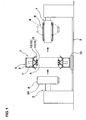
- Fig. 1 shows a raw tire forming apparatus 1 of the present invention.
- the raw tire forming apparatus 1 is disposed between a tread ring forming drum 2 which forms a tread ring A, and a former 3 which expands a raw tire base body B from its cylindrical shape into a toroidal shape.
- the raw tire forming apparatus 1 transfers the tread ring A received from the tread ring forming drum 2 onto the former 3 while aligning the tread ring A with an outer periphery of the raw tire base body B on the former 3.
- the raw tire forming apparatus 1 also pushes an inner peripheral surface of the tread ring A against the toroidal raw tire base body B and pastes the same. That is, the raw tire forming apparatus 1 of the present invention functions as a transfer which transfers the tread ring and as a stitcher for pasting the tread ring.
- the conventional special pasting apparatus can be eliminated and the installation space can effectively be utilized.
- the tread ring forming drum 2 is of a known structure having a rotatable drum whose diameter can be reduced.
- a tread constituent member including a belt ply a1 and a tread rubber a2 is wound on the drum 2A, thereby forming the annular tread ring A (shown in Fig. 6(A)).
- the former 3 is a single former of a known structure used in a so-called single stage forming method.
- a tire member including a carcass ply b1 is wound in sequence, and a cylindrical raw tire base body B (shown in Fig. 6(B)) is formed.
- reference number b2 represents an inner linear rubber
- reference number b3 represents a bead core
- reference number b4 represents a bead apex rubber
- reference number b5 represents a sidewall rubber.
- the former 3 may be a second former used in a two stage forming method. In such a case, a raw tire base body B which is separately formed on the first former is provided on the former 3.
- the raw tire forming apparatus 1 includes a ring-like base body 5 which moves between the tread ring forming drum 2 and the former 3 which are concentrically disposed, and a pasting means 6 supported by this ring-like base body 5 as shown in Fig. 1.
- the pasting means 6 includes a grasping tool 11 capable of grasping the tread ring A, and a pushing-down pasting tool 12 which pushes down the tread ring shoulder side portion As and pastes the same on the toroidal raw tire base body B.
- the ring-like base body 5 is an annular body which is concentric with the former 3.
- the ring-like base body 5 has a rectangular cross section comprising an inner peripheral plate portion 7 and an outer peripheral plate portion 8 connected with each other through side plates.
- the ring-like base body 5 is provided at its lower end with a running-stage 10 which can run along rails 9 provided between the tread ring forming drum 2 and the former 3.
- the ring-like base body 5 can relatively move with respect to the former 3 in an axial direction of the tire.
- the grasping tool 11 includes a plurality of segments 13 which can move forward and backward in a radial direction. If the segments 13 move forward, i.e., inward of an inner surface of the ring-like base body 5, the segments 13 abut against the outer peripheral surface of the tread ring A and grasp the tread ring A. Although the segments 13 are supported by a rod end of a cylinder 14 fixed to the inner peripheral plate portion 7 in this embodiment, the segments 13 may be supported by any of known diameter-reducing mechanism such that the segments 13 can move while reducing the diameter.
- the pushing-down pasting tool 12 includes an expandable annular rubber tube body 15 disposed on each side of the segment 13 as shown in Fig. 3.
- the pushing-down pasting tool 12 includes a guide tool 16 which guides the expansion of the rubber tube body 15.
- Each rubber tube body 15 is a soft annular body having a circular cross section and a rubber thickness of 1 to 4 mm.
- the rubber tube body 15 continuously extends in a circumferential direction of the tire.
- 2 to 5 bolt-like mounting hardware 20 including air valves 20A are projecting from an outer peripheral edge of the rubber tube body 15 at distances from one another in the circumferential direction.
- the mounting hardware 20 other than the air valves 20A is fixed to the rubber tube body 15 by welding or the like.
- the mounting hardware 20 is mounted on the ring-like base body 5 with play therebetween using a double nut or the like.
- the mounting hardware 20 other than the air valve 20A may be fastened using a rubber band-like fastening cord 21 with play with respect to the ring-like base body 5.
- the fastening cord 21 is preferably easily expandable and has lower elasticity than the rubber tube body 15.
- the rubber tube body 15 is supported at a point, and the rubber tube body 15 is mounted such that it can inclined around the supporting point by play and it can easily be deviated in position.
- the guide tool 16 is formed into a V-shape having an inner guide piece 16i and an guide piece 16o each extending in the circumferential direction on each side of the rubber tube body 15.
- the inner and outer guide pieces 16i and 16o incline in directions from radially outside to inside such as to separate away from the rubber tube body 15.
- an inclination angle ⁇ 1 between the inner guide piece 16i and the axial direction of the tire is in a range of 50 to 90°
- an inclination angle ⁇ 2 between the outer guide piece 16o and the axial direction of the tire is in a range of 30 to 70° and is equal to or smaller than the inclination angle ⁇ 1
- the guide tool 16 guides such that the rubber tube body 15 expands outward as possible in the axial direction of the tire.
- the segments 13 of the raw tire forming apparatus 1 are allowed to advance radially inward and to abut against the outer peripheral surface of the tread ring A on the tread ring forming drum 2.
- the tread ring A is received from the tread ring forming drum 2 and grasped (grasping step).
- the tread ring forming drum 2 reduces its diameter to release the tread ring A.
- the raw tire forming apparatus 1 is allowed to move to a predetermined position of the former 3 along the rails 9, and the grasped tread ring A is aligned with the raw tire base body B on the former 3 (aligning step).
- the raw tire base body B on the former 3 is expanded from its cylindrical shape into the toroidal shape by charging the internal pressure.
- a central portion of the grasped tread ring A comes into contact with a central portion of the toroidal raw tire base body B under pressure and is pasted (expansion step).
- a bladder, a rubber tube and the like are made of rubber. Therefore, when it expands from its weak (thin) film portion and it naturally expands eccentrically. This eccentrically or unevenly expanded portion first pushes the tread ring or strongly pushes the tread ring. At that time, if a reinforcing layer or the like is inserted into the rubber tube and fixed without play, since a side of the rubber tube is deformed easily and a force can not be released, and the tread ring is pushed unevenly, the tread edge portion meanders and the uniformity is adversely affected.
- the rubber tube body 15 is mounted with play so that the rubber tube body 15 can easily be deviated in position.
- the rubber tube body 15 itself moves (changes its attitude) and the uneven force can be released. That is, even when stress variation in the circumferential direction or radial direction is generated in the rubber tube body 15 in some cases, the rubber tube body 15 itself moves to release the force as it is expanded, the reaction force allows it to be centered automatically with respect to the tread ring A, and the auto-correcting function can be exhibited.
- the pushing-down pasting tool 12 can precisely paste the tread ring A and the raw tire base body B with high quality. Further, the rubber tube body 15 does not require high part precision and assembling precision, and there is a merit that a shape and a structure having a simple circular cross section can be employed as the rubber tube body 15.
- the pushing-down pasting tool 12 expands the rubber tube body 15 while pushing the central portion of the tread ring A by the segments 13. Therefore, air below the tread ring A can be released toward the tread edge, and it is possible to reliably discharge the remaining air from the entire region including the central portion. Since the pasting operation can be carried out simultaneously with the transfer of the tread ring A into the raw tire base body B, the operation time can be largely reduced, and also the step cycle time can be reduced largely.
- a distance L1 in the axial direction of the tire between the segment 13 and a tip end of the inner guide piece 16i is preferably greater than 0 mm and equal to or smaller than 10 mm. If the distance L1 is 0 mm or less, when the segment 13 advances or retreats, it collides against the inner guide piece 16i. If the distance L1 exceeds 10 mm, there is an adverse possibility that air remains in this distance L1.
- the cross section diameter d of the rubber tube body 15 is preferably in a range of 25 to 100% of the tread width TW of the tread ring A (shown in Fig. 6(A)), and a distance L2 in the axial direction of the tire between the cross section center and an outer end of the widest belt ply a1 is preferably in a range of -5 to +10 mm (outer side from the outer end in the axial direction of the tire is +).
- the cross section diameter d is smaller than -25% and if the distance L2 is smaller than -5 mm, a rubber tube body 15 having a large expansion coefficient is required for pasting it up to the tread edge, the endurance strength of the rubber tube body 15 is lowered, and it takes time to charge the pressure. If the cross section diameter d exceeds 100%, the apparatus is increased in size, the installation space can not be utilized effectively, and it takes time to charge the pressure. If the distance L2 exceeds +10 mm, air is prone to remain in the tread ring shoulder side portion As. When the cross section diameter d is not a perfect circle, a diameter of the smallest perfect circle in a perfect circle capable of surrounding the cross section of the rubber tube body 15 (except air valve) is defined as the cross section diameter d.
- the inner diameter D1 of the rubber tube body 15 is preferably in a range of 100 to 110% of the outer diameter D2 of the tread ring A. If the inner diameter D1 exceeds 110% of the outer diameter D2, a rubber tube body 15 having a large expansion coefficient is required, the endurance strength of the rubber tube body 15 is lowered, and it takes time to charge the pressure.
- a charging internal pressure P1 of the rubber tube body 15 is preferably 20 to 95% of a charging internal pressure P2 of the raw tire base body B, and more preferably 30 to 80%. If the charging internal pressure P1 is smaller than 20% of the charging internal pressure P2, the pushing-down force of the tread ring shoulder side portion As is insufficient, or the pushing-down force against the raw tire base body B is insufficient, and there is an adverse possibility that the pasting operation can not be carried out reliably. If the charging internal pressure P1 exceeds 95% of the charging internal pressure P2, the raw tire base body B is deformed or the like when the pasting operation is carried out.
- the charging internal pressure P2 of the raw tire base body B can be reduced to about 30 to 80% (e.g., 42 to 112 kPa) of the conventional stitching system (shown in Fig. 7) using a disk e.
- the charging internal pressure P2 can be suppressed.
- the charging internal pressure P2 of the raw tire base body B is usually set to a value as high as about 140 kPa, and the pushing force of the disk 3 is set to a value as high as about 140 kPa. This is because that if the charging internal pressure P2 is lower than P3, the raw tire base body B is pushed by the disk e and is deformed inward. If the pushing force P3 is 140 kPa or lower, a crimping force becomes excessively weak, the tread ring jumps and returns and the pasting operation can not be carried out. To prevent this, it is necessary to extremely reduce the rotation speed of the raw tire base body B, and the operation efficiency is largely lowered. Thus, the charging internal pressure is set to the high pressure.
- the raw tire base body B is not rotated and pushed on the circumference at a dash and thus, it is possible to push strongly within sufficient crimping time. Therefore, the charging internal pressure P1 of the rubber tube body 15 can be set to a low value while reliably carrying out the pasting operation, and the charging internal pressure P2 of the raw tire base body B can also be reduced.
- RFV radial force variation
- LFV lateral force variation
- Table 1 Conventional Example Present Example Charging internal pressure P2 (Kpa) of raw tire base body 140 80 Charging internal pressure P1 (Kpa) of rubber tube body - 50 Pressing force P3 (Kpa) of disk 140 - Pasting operation time (second) 10 5 Uniformity ⁇ RFV 100 87 ⁇ LFV 100 44 Air remaining state 0 0
- Table 2 Rubber tube body ⁇ Rubber thickness (mm) 1.5 ⁇ Cross section diameter d (mm) 62 (radio d/TW) 85% ⁇ Inner diameter D1 (mm) 505 (radio D1/D2) 103% ⁇ Distance L2 (mm) 5 Guide tool ⁇ Inclination angle ⁇ 1 (°) 55 ⁇ Inclination angle ⁇ 2 (°) 45 ⁇ Distance L1 (mm) 5 * Tread width TW is 146 mm.
- Outer diameter D2 of tread ring is 488 m.
- the present invention since the present invention has both the transfer function of the tread ring and the stitcher function, the installation space can effectively be utilized, and the transfer operation and the pasting operation of the tread ring can be carried out at the same time. Therefore, the step cycle time can largely be reduced. It is unnecessary to pay much attention to misalignment, eccentricity and uneven expansion of the rubber tube, the pasting operation between the tread ring and the raw tire base body can be carried out precisely with high quality without requiring high precision of parts of the rubber tube body itself and high assembling precision. It is possible to prevent air from remaining in the entire region under the tread ring.
Description
- The present invention relates to a raw tire forming apparatus and a raw tire forming method capable of precisely and efficiently pasting a tread ring to a raw tire base body, enhancing the uniformity of a finished tire and enhancing the productivity, according to the pre-characterizing part of claim 1 and of claim 4, respectively.
- As shown in Fig. 7, in a producing step of a raw tire (tire before vulcanization) in a radial tire, it is necessary to paste a cylindrical tread ring A to a raw tire base body B which is expanded in a toroidal shape. According to a normal pasting method, a rotatable disk e which is called a tread stitcher is pushed against the tread ring A, the raw tire base body B is rotated and in this state, the disk e is gradually moved outward in the axial direction of the tire and inward in the radial direction, thereby pasting the entire tread ring A.
- In the stitching method using the disk e, the carcass cord is deviated from the radial direction by twist caused by rotation torque, an angle in the lateral direction is different in the belt cord, and the uniformity of a finished tire is adversely influenced. Since the shoulder side portion of the tread ring A is gradually pushed down, it takes time for pasting the tread ring A, and the productivity of the raw tire is deteriorated.
- Solutions of this problem have been proposed in patent document 1 (Japanese Patent Application Laid-open No. S60-132745), patent document 2 (Japanese Patent Application Laid-open No. 2003-071947) and patent document 3 (Japanese Patent Application Laid-open No. 2003-071948).
- According to the patent document 1, however, a wide tread ring integrally provided with a sidewall rubber is used to prevent a tread edge from becoming cracked. Thus, it is necessary to crimp a wide region in the vicinity of the bead portion. Therefore, it is necessary to increase the expansion coefficient of the tube bladder, but if the expansion coefficient is increased, a large difference is prone to be generated in the expansion coefficient on the circumference, and the pasting operation can not be carried out uniformly in some cases.
- In the patent document 2, since the bladder is held by a cramp member, concentric severity is high because of positional relation between the clamp body and a raw tire base body. Thus, even if there is a small deviation in concentric state, variation is generated in the cramping force, the tread edge meanders and the quality is adversely affected. Since the center of the bladder is deviated toward the tread with respect to the center of the clamp member, there is an adverse possibility that air remains below the tread ring.
- In the
patent document 3, since the rigidity is changed depending upon a portion of the tube, it is necessary to enhance the precision of a part of the tube and to precisely control the position where the tread ring starts abutting. Thus, it is important to form the tube precisely and to perform a high level maintenance. Since the clamp is fixed, there is a problem that concentric severity is high like the patent document 2. - In any of the patent documents 1 to 3, the step for moving the pasting apparatus to a predetermined position to crimp after the tread ring is transferred to the raw tire base body requires the same installation space and the cycle time of step as those of the conventional technique like the conventional disk.
- An apparatus according to the pre-characterizing portion of claim 1 and a method according to the pre-characterizing portion of claim 4 are disclosed by EP-A-0071838. Further raw tire forming apparatuses and raw tire forming methods are disclosed by US-A-5413653, US-A-5486260, US-A-4178198 and JP 60-132745 A.
- It is an object of the present invention to provide a raw tire forming apparatus and a raw tire forming method capable of precisely and efficiently paste a tread ring to a raw tire base body while reducing the installation space and step cycle time without requiring high precision of the rubber tube body itself and of the mounting operation of the rubber tube body.
- This object is achieved by an apparatus according to claim 1 and a method according to claim 4.
- Particular embodiments of the invention are the subject of the respective dependent claims.
-
- Fig. 1 is a side view showing an embodiment of a raw tire forming apparatus of the present invention;
- Fig. 2 is a front view thereof;
- Fig. 3 is an enlarged sectional view of a pasting means;
- Fig. 4 is a sectional view of an operating state of the pasting means;
- Fig. 5 (A) is a front view of a rubber tube body, Fig. 5 (B) is a diagram showing one example of a mounting state of the rubber tube body, and Fig. 5 (C) is a diagram showing another example of the mounting state;
- Figs. 6(A) and (B) are schematic sectional views of a tread ring and a raw tire base body; and
- Fig. 7 is a diagram for explaining a conventional technique.
- An embodiment of the present invention will be explained with reference to the drawings.
- Fig. 1 shows a raw tire forming apparatus 1 of the present invention. The raw tire forming apparatus 1 is disposed between a tread ring forming drum 2 which forms a tread ring A, and a former 3 which expands a raw tire base body B from its cylindrical shape into a toroidal shape.
- The raw tire forming apparatus 1 transfers the tread ring A received from the tread ring forming drum 2 onto the former 3 while aligning the tread ring A with an outer periphery of the raw tire base body B on the former 3. The raw tire forming apparatus 1 also pushes an inner peripheral surface of the tread ring A against the toroidal raw tire base body B and pastes the same. That is, the raw tire forming apparatus 1 of the present invention functions as a transfer which transfers the tread ring and as a stitcher for pasting the tread ring. Thus, the conventional special pasting apparatus can be eliminated and the installation space can effectively be utilized.
- Here, the tread ring forming drum 2 is of a known structure having a rotatable drum whose diameter can be reduced. A tread constituent member including a belt ply a1 and a tread rubber a2 is wound on the
drum 2A, thereby forming the annular tread ring A (shown in Fig. 6(A)). - In this embodiment, the former 3 is a single former of a known structure used in a so-called single stage forming method. A tire member including a carcass ply b1 is wound in sequence, and a cylindrical raw tire base body B (shown in Fig. 6(B)) is formed. In the drawings, reference number b2 represents an inner linear rubber, reference number b3 represents a bead core, reference number b4 represents a bead apex rubber, and reference number b5 represents a sidewall rubber. The former 3 may be a second former used in a two stage forming method. In such a case, a raw tire base body B which is separately formed on the first former is provided on the former 3.
- Next, the raw tire forming apparatus 1 includes a ring-
like base body 5 which moves between the tread ring forming drum 2 and the former 3 which are concentrically disposed, and a pasting means 6 supported by this ring-like base body 5 as shown in Fig. 1. The pasting means 6 includes agrasping tool 11 capable of grasping the tread ring A, and a pushing-downpasting tool 12 which pushes down the tread ring shoulder side portion As and pastes the same on the toroidal raw tire base body B. - In this embodiment, the ring-
like base body 5 is an annular body which is concentric with the former 3. The ring-like base body 5 has a rectangular cross section comprising an innerperipheral plate portion 7 and an outer peripheral plate portion 8 connected with each other through side plates. The ring-like base body 5 is provided at its lower end with a running-stage 10 which can run alongrails 9 provided between the tread ring forming drum 2 and the former 3. Thus, the ring-like base body 5 can relatively move with respect to the former 3 in an axial direction of the tire. - The
grasping tool 11 includes a plurality ofsegments 13 which can move forward and backward in a radial direction. If thesegments 13 move forward, i.e., inward of an inner surface of the ring-like base body 5, thesegments 13 abut against the outer peripheral surface of the tread ring A and grasp the tread ring A. Although thesegments 13 are supported by a rod end of acylinder 14 fixed to the innerperipheral plate portion 7 in this embodiment, thesegments 13 may be supported by any of known diameter-reducing mechanism such that thesegments 13 can move while reducing the diameter. - Next, the pushing-down
pasting tool 12 includes an expandable annularrubber tube body 15 disposed on each side of thesegment 13 as shown in Fig. 3. In this embodiment, the pushing-downpasting tool 12 includes aguide tool 16 which guides the expansion of therubber tube body 15. - Each
rubber tube body 15 is a soft annular body having a circular cross section and a rubber thickness of 1 to 4 mm. Therubber tube body 15 continuously extends in a circumferential direction of the tire. As shown in Fig. 5 (A), 2 to 5 bolt-like mounting hardware 20 includingair valves 20A are projecting from an outer peripheral edge of therubber tube body 15 at distances from one another in the circumferential direction. Themounting hardware 20 other than theair valves 20A is fixed to therubber tube body 15 by welding or the like. As shown in Fig. 5 (B), themounting hardware 20 is mounted on the ring-like base body 5 with play therebetween using a double nut or the like. - As another mounting method, as shown in Fig. 5(C), the
mounting hardware 20 other than theair valve 20A may be fastened using a rubber band-like fastening cord 21 with play with respect to the ring-like base body 5. In that case, thefastening cord 21 is preferably easily expandable and has lower elasticity than therubber tube body 15. In any cases, therubber tube body 15 is supported at a point, and therubber tube body 15 is mounted such that it can inclined around the supporting point by play and it can easily be deviated in position. - As shown in Fig. 3, the
guide tool 16 is formed into a V-shape having aninner guide piece 16i and an guide piece 16o each extending in the circumferential direction on each side of therubber tube body 15. The inner andouter guide pieces 16i and 16o incline in directions from radially outside to inside such as to separate away from therubber tube body 15. At that time, it is preferable that an inclination angle α1 between theinner guide piece 16i and the axial direction of the tire is in a range of 50 to 90°, an inclination angle α2 between the outer guide piece 16o and the axial direction of the tire is in a range of 30 to 70° and is equal to or smaller than the inclination angle α1, and theguide tool 16 guides such that therubber tube body 15 expands outward as possible in the axial direction of the tire. - At the position of the tread ring forming drum 2, the
segments 13 of the raw tire forming apparatus 1 are allowed to advance radially inward and to abut against the outer peripheral surface of the tread ring A on the tread ring forming drum 2. With this, the tread ring A is received from the tread ring forming drum 2 and grasped (grasping step). When the tread ring A is received, the tread ring forming drum 2 reduces its diameter to release the tread ring A. - Then, the raw tire forming apparatus 1 is allowed to move to a predetermined position of the former 3 along the
rails 9, and the grasped tread ring A is aligned with the raw tire base body B on the former 3 (aligning step). In this state, the raw tire base body B on the former 3 is expanded from its cylindrical shape into the toroidal shape by charging the internal pressure. At that time, as shown in Fig. 3, a central portion of the grasped tread ring A comes into contact with a central portion of the toroidal raw tire base body B under pressure and is pasted (expansion step). - Thereafter, the diameter-reduced state of the
segment 13 is maintained, and in this state, the internal pressure is charged into therubber tube body 15 of the pushing-downpasting tool 12, thereby largely expanding therubber tube body 15 as shown in Fig. 4. With this, the tread ring shoulder side portion As is pushed down and is pasted on the raw tire base body B (pasting step) . At that time, the expansion of therubber tube body 15 is limited and guided by the inner andouter guide pieces - Here, a bladder, a rubber tube and the like are made of rubber. Therefore, when it expands from its weak (thin) film portion and it naturally expands eccentrically. This eccentrically or unevenly expanded portion first pushes the tread ring or strongly pushes the tread ring. At that time, if a reinforcing layer or the like is inserted into the rubber tube and fixed without play, since a side of the rubber tube is deformed easily and a force can not be released, and the tread ring is pushed unevenly, the tread edge portion meanders and the uniformity is adversely affected.
- In this embodiment, the
rubber tube body 15 is mounted with play so that therubber tube body 15 can easily be deviated in position. Thus, when the unevenly expanded portion is generated and such portion tries to come into strong contact with the tread ring A, therubber tube body 15 itself moves (changes its attitude) and the uneven force can be released. That is, even when stress variation in the circumferential direction or radial direction is generated in therubber tube body 15 in some cases, therubber tube body 15 itself moves to release the force as it is expanded, the reaction force allows it to be centered automatically with respect to the tread ring A, and the auto-correcting function can be exhibited. - Therefore, the pushing-down
pasting tool 12 can precisely paste the tread ring A and the raw tire base body B with high quality. Further, therubber tube body 15 does not require high part precision and assembling precision, and there is a merit that a shape and a structure having a simple circular cross section can be employed as therubber tube body 15. The pushing-downpasting tool 12 expands therubber tube body 15 while pushing the central portion of the tread ring A by thesegments 13. Therefore, air below the tread ring A can be released toward the tread edge, and it is possible to reliably discharge the remaining air from the entire region including the central portion. Since the pasting operation can be carried out simultaneously with the transfer of the tread ring A into the raw tire base body B, the operation time can be largely reduced, and also the step cycle time can be reduced largely. - As shown in Fig. 3, a distance L1 in the axial direction of the tire between the
segment 13 and a tip end of theinner guide piece 16i is preferably greater than 0 mm and equal to or smaller than 10 mm. If the distance L1 is 0 mm or less, when thesegment 13 advances or retreats, it collides against theinner guide piece 16i. If the distance L1 exceeds 10 mm, there is an adverse possibility that air remains in this distance L1. - In a standard state in which 1 atmospheric pressure is charged into the
rubber tube body 15, the cross section thereof is substantially circular in shape, the cross section diameter d of therubber tube body 15 is preferably in a range of 25 to 100% of the tread width TW of the tread ring A (shown in Fig. 6(A)), and a distance L2 in the axial direction of the tire between the cross section center and an outer end of the widest belt ply a1 is preferably in a range of -5 to +10 mm (outer side from the outer end in the axial direction of the tire is +). If the cross section diameter d is smaller than -25% and if the distance L2 is smaller than -5 mm, arubber tube body 15 having a large expansion coefficient is required for pasting it up to the tread edge, the endurance strength of therubber tube body 15 is lowered, and it takes time to charge the pressure. If the cross section diameter d exceeds 100%, the apparatus is increased in size, the installation space can not be utilized effectively, and it takes time to charge the pressure. If the distance L2 exceeds +10 mm, air is prone to remain in the tread ring shoulder side portion As. When the cross section diameter d is not a perfect circle, a diameter of the smallest perfect circle in a perfect circle capable of surrounding the cross section of the rubber tube body 15 (except air valve) is defined as the cross section diameter d. - In this standard state, the inner diameter D1 of the
rubber tube body 15 is preferably in a range of 100 to 110% of the outer diameter D2 of the tread ring A. If the inner diameter D1 exceeds 110% of the outer diameter D2, arubber tube body 15 having a large expansion coefficient is required, the endurance strength of therubber tube body 15 is lowered, and it takes time to charge the pressure. - A charging internal pressure P1 of the
rubber tube body 15 is preferably 20 to 95% of a charging internal pressure P2 of the raw tire base body B, and more preferably 30 to 80%. If the charging internal pressure P1 is smaller than 20% of the charging internal pressure P2, the pushing-down force of the tread ring shoulder side portion As is insufficient, or the pushing-down force against the raw tire base body B is insufficient, and there is an adverse possibility that the pasting operation can not be carried out reliably. If the charging internal pressure P1 exceeds 95% of the charging internal pressure P2, the raw tire base body B is deformed or the like when the pasting operation is carried out. - In this invention, the charging internal pressure P2 of the raw tire base body B can be reduced to about 30 to 80% (e.g., 42 to 112 kPa) of the conventional stitching system (shown in Fig. 7) using a disk e. Thus, deformation of the raw tire base body B caused by this charging internal pressure P2 can be suppressed.
- In the case of the conventional stitching system, the charging internal pressure P2 of the raw tire base body B is usually set to a value as high as about 140 kPa, and the pushing force of the
disk 3 is set to a value as high as about 140 kPa. This is because that if the charging internal pressure P2 is lower than P3, the raw tire base body B is pushed by the disk e and is deformed inward. If the pushing force P3 is 140 kPa or lower, a crimping force becomes excessively weak, the tread ring jumps and returns and the pasting operation can not be carried out. To prevent this, it is necessary to extremely reduce the rotation speed of the raw tire base body B, and the operation efficiency is largely lowered. Thus, the charging internal pressure is set to the high pressure. - In this embodiment, however, the raw tire base body B is not rotated and pushed on the circumference at a dash and thus, it is possible to push strongly within sufficient crimping time. Therefore, the charging internal pressure P1 of the
rubber tube body 15 can be set to a low value while reliably carrying out the pasting operation, and the charging internal pressure P2 of the raw tire base body B can also be reduced. - Although the especially preferred embodiment of the present invention has been described in detail, the invention is not limited to the embodiment, and the invention can variously be modified.
- Ten raw tires in which tread rings and raw tire base bodies are pasted on each other were formed using the conventional stitching apparatus (Fig. 7) using the raw tire forming apparatus and the disk e of the present invention shown in Fig. 1, the raw tires were vulcanized and formed, the uniformity (RFV, LFV), air remaining state under the tread ring, and the pasting operation time of the finished tires (size of 145/65R13) were compared, and result thereof are shown in Table 1. The specifications other than the pasting methods of the tread rings in the examples of the present tires and the conventional tires are the same. The specification of the raw tire forming apparatus is shown in Table 2.
- In accordance with JASOC607, RFV (radial force variation) and LFV (lateral force variation) of the ten prototyped tires were measured under the conditions of rim of 13×4 . 5J, internal pressure of 200 kPa and a load of 2.4 kN, and the average values thereof were indicated with indices where a comparative example is 100. A lower index shows more excellent uniformity.
- The completed or finished tire was disassembled, and the presence or absence of remaining air was visually checked.
Table 1 (PS3568) Conventional Example Present Example Charging internal pressure P2 (Kpa) of raw tire base body 140 80 Charging internal pressure P1 (Kpa) of rubber tube body - 50 Pressing force P3 (Kpa) of disk 140 - Pasting operation time (second) 10 5 Uniformity · RFV 100 87 · LFV 100 44 Air remaining state 0 0 Table 2 (PS3568) Rubber tube body · Rubber thickness (mm) 1.5 · Cross section diameter d (mm) 62 (radio d/TW) 85% · Inner diameter D1 (mm) 505 (radio D1/D2) 103% · Distance L2 (mm) 5 Guide tool · Inclination angle α1 (°) 55 · Inclination angle α2 (°) 45 · Distance L1 (mm) 5 * Tread width TW is 146 mm. - Outer diameter D2 of tread ring is 488 m.
- As described above, since the present invention has both the transfer function of the tread ring and the stitcher function, the installation space can effectively be utilized, and the transfer operation and the pasting operation of the tread ring can be carried out at the same time. Therefore, the step cycle time can largely be reduced. It is unnecessary to pay much attention to misalignment, eccentricity and uneven expansion of the rubber tube, the pasting operation between the tread ring and the raw tire base body can be carried out precisely with high quality without requiring high precision of parts of the rubber tube body itself and high assembling precision. It is possible to prevent air from remaining in the entire region under the tread ring.
Claims (10)
- A raw tire forming apparatus (1) in which a position of a tread ring (A) including a belt ply (a1 and a tread rubber (a2) is aligned with an outer periphery of a raw tire base body (B) on a former (3) in which tire members including a carcass ply (b1) are combined, the raw tire base body (B) is expanded from its cylindrical shape to its toroidal shape, and the tread ring (A) is pushed against the toroidal raw tire base body (B), the raw tire forming apparatus (1) including pasting means (6) for pasting an inner peripheral surface of the tread ring (A) to the raw tire base body (B), wherein
the pasting means (6) includes a ring-like base body (5) which moves concentrically and relatively with the former (3) in an axial direction of the tire,
the ring-like base body (5) includes a grasping tool (11) having a plurality of segments (13) capable of advancing and retracting in a radial direction, the segments (13) capable of abutting against an outer peripheral surface of the tread ring (A) to grasp the tread ring (A) by advancing inward of an inner surface of the ring-like base body (5), and
a pushing-down pasting tool (12) having annular rubber tube bodies (15) extending in the circumferential direction of the tire which are disposed on each side of the grasping tool (11), said rubber tube bodies_(15) being capable of expanding to push down shoulder side portions (As) of the tread ring (A), thereby pasting the shoulder side portions (As) on the toroidal raw tire base body (B), whereby means are provided for expanding said rubber tube bodies (15) by charging an internal pressure, characterized in that each of the annular rubber tube bodies (15) is attached to the ring-like base body (5) with play so as to be able to deviate in position, and in that each of the annular rubber tube bodies (15) has a substantially circular cross section having a diameter (d) of 25 to 100% of the tread width (TW) of the tread ring (A) when an inner pressure of 1 atm is applied thereto. - The raw tire forming apparatus (1) according to claim 1, wherein the pushing-down pasting tool (12) includes a guide tool (16) having an inner guide piece (16i) and an outer guide piece (16o) each of which extends in a circumferential direction inside and outside of the rubber tube body (15) in the axial direction of the tire and guides the expansion of the rubber tube body (15), each of the inner and outer guide piece (16i, 16o) is inclined in a direction away from the rubber body (15) from outer side toward inner side in the radial direction.
- The raw tire forming apparatus according to claim 1 or 2, wherein the inner guide piece (16i) has an inclination angle α1 of 50 to 90° with respect to the axial direction of the tire, the outer guide piece (16o) has an inclination angle α2 of 30 to 70° with respect to the axial direction of the tire, and the inclination angle α2 is equal to or smaller than the inclination angle α1 (α2≤α1).
- A method for producing a raw tire comprising:a grasping step for grasping a tread ring (A) including a belt ply (a1) and a tread rubber (a2) by a grasping tool (11) comprising a plurality of segments (13) and provided in a ring-like base body (5) which is able to move concentrically with a former (3) in the axial direction of the tire,a step for forming a cylindrical raw tire base body (B) by winding tire members including a carcass ply (b1) on the former (3),a positioning step for positioning the grasped tread ring (A) with respect to the raw tire base body (B) on the former (3) by relative movement between the ring-like base body (5) and the former (3),an expanding step for pushing and pasting the raw tire base body (B) to and against a central portion of the grasped tread ring (A) by expanding the raw tire base body (B) on the former (3) from its cylindrical shape into its toroidal shape by applying an internal pressure to the cylindrical raw tire base body (B), anda pasting step for pasting the inner peripheral surface of the tread ring (A) to the outer peripheral surface of the toroidal raw tire base body (B) by expanding annular rubber tube bodies (15) extending in the circumferential direction of the tire which are disposed on each side of the grasping tool (11), thereby pushing down shoulder side portions (As) of the tread ring (A) so as to paste the tread ring (A) to the toroidal raw tire base body (B), whereby, the expansion of the annular rubber tube bodies (15) is performed by application of an internal pressure to the rubber tube bodies (15), characterized in that each of the annular rubber tube bodies (15) is attached to the annular base body (5) with play so as to be able to deviate in position, and in that each of the annular rubber tube bodies (15) has a substantially circular cross section having a diameter (d) of 25 to 100% of the tread width (TW) of the tread ring (A) when an inner pressure of 1 atm is applied thereto.
- The method according to claim 4, wherein each of the rubber tube bodies (15) expands while being guided by an inner guide piece (16i) and an outer guide piece (16o) which extend in the circumferential direction of the tire at axially inside and outside of each of the rubber tube bodies (15).
- The method according to claim 4 or 5, wherein the internal pressure of the rubber tube bodies (15) is 20 to 95% of the internal pressure of the raw tire base body (B).
- The method according to any one of claims 4 to 6, wherein the distance in the axial direction of the tire between the center of the substantially circular cross section of each rubber tube body (15) and the axially outer end of the widest belt ply (a1) is from -5 to +10 mm.
- The method according to claim 5, wherein the inner and outer guide pieces (16i, 16o) are disposed to form a V-shape in cross section such that the distance between them increases toward the radially inward, thereby limiting expansion of each rubber tube body (15) in the axially inward and outward directions.
- The method according to claim 8, wherein the inclination angle (α2) of the outer guide piece (16o) to the axial direction is smaller than the inclination angle (α1) of the inner guide piece (16i) to the axial direction.
- The method according to any one of claims 4 to 9, wherein each of the annular rubber tube bodies (15) is supported by the ring-like base body (5) with play so as to be able to deviate in position through mounting hardware including an air valve.
Applications Claiming Priority (2)
| Application Number | Priority Date | Filing Date | Title |
|---|---|---|---|
| JP2003179992A JP4065220B2 (en) | 2003-06-24 | 2003-06-24 | Raw tire forming apparatus and raw tire forming method |
| JP2003179992 | 2003-06-24 |
Publications (3)
| Publication Number | Publication Date |
|---|---|
| EP1491324A2 EP1491324A2 (en) | 2004-12-29 |
| EP1491324A3 EP1491324A3 (en) | 2005-10-19 |
| EP1491324B1 true EP1491324B1 (en) | 2007-05-09 |
Family
ID=33411064
Family Applications (1)
| Application Number | Title | Priority Date | Filing Date |
|---|---|---|---|
| EP04014132A Expired - Fee Related EP1491324B1 (en) | 2003-06-24 | 2004-06-16 | Method and apparatus for forming a raw tire |
Country Status (5)
| Country | Link |
|---|---|
| US (1) | US7208061B2 (en) |
| EP (1) | EP1491324B1 (en) |
| JP (1) | JP4065220B2 (en) |
| CN (1) | CN100562426C (en) |
| DE (1) | DE602004006339T2 (en) |
Families Citing this family (18)
| Publication number | Priority date | Publication date | Assignee | Title |
|---|---|---|---|---|
| DE102004058522A1 (en) * | 2004-12-04 | 2006-06-14 | Continental Aktiengesellschaft | Method and device for constructing a radial tire |
| DE102005054507A1 (en) * | 2005-11-16 | 2007-05-24 | Continental Aktiengesellschaft | A method of manufacturing a belt package for a pneumatic vehicle tire |
| JP5228052B2 (en) * | 2007-09-27 | 2013-07-03 | ピレリ・タイヤ・ソチエタ・ペル・アツィオーニ | Method and plant for manufacturing tires for vehicle wheels |
| JP5038528B2 (en) | 2008-04-18 | 2012-10-03 | ピレリ・タイヤ・ソチエタ・ペル・アツィオーニ | Method and apparatus for assembling tires |
| JP2010208198A (en) * | 2009-03-11 | 2010-09-24 | Bridgestone Corp | Method and apparatus for manufacturing tire |
| JP5306936B2 (en) * | 2009-08-06 | 2013-10-02 | 株式会社ブリヂストン | Tire conveying member holding and conveying pressure bonding apparatus and green tire manufacturing method |
| JP5044629B2 (en) * | 2009-11-10 | 2012-10-10 | 住友ゴム工業株式会社 | Raw tire molding apparatus and method for manufacturing pneumatic tire |
| NL2004734C2 (en) * | 2010-05-18 | 2011-11-21 | Vmi Holland Bv | METHOD AND COMPOSITION FOR MANUFACTURING A GREEN BAND |
| JP2011255617A (en) | 2010-06-10 | 2011-12-22 | Bridgestone Corp | Tire manufacturing device and tire manufacturing method |
| JP5732819B2 (en) * | 2010-11-09 | 2015-06-10 | 横浜ゴム株式会社 | Unvulcanized rubber member and unvulcanized tire crimping device |
| JP5695413B2 (en) * | 2010-12-22 | 2015-04-08 | 住友ゴム工業株式会社 | Raw tire forming method |
| CN103501981B (en) | 2011-04-30 | 2016-08-17 | 米其林研究和技术股份有限公司 | For the method and apparatus coupling tyre surface |
| JP5778980B2 (en) * | 2011-05-13 | 2015-09-16 | 住友ゴム工業株式会社 | Evaluation of misalignment between tread transfer and shaping former using tread transfer |
| CN103619571B (en) | 2011-06-30 | 2016-08-17 | 米其林研究和技术股份有限公司 | For the method and apparatus that tread rings is installed on carcass |
| CN103302882B (en) * | 2013-07-01 | 2015-09-23 | 三角轮胎股份有限公司 | Tire building operation tyre surface press-roller device |
| JP6474603B2 (en) * | 2014-12-22 | 2019-02-27 | 住友ゴム工業株式会社 | Tire forming former centering confirmation jig |
| JP6484107B2 (en) * | 2015-05-19 | 2019-03-13 | 住友ゴム工業株式会社 | Raw tire forming method |
| US20170144400A1 (en) * | 2015-11-24 | 2017-05-25 | The Goodyear Tire & Rubber Company | Method for manufacturing a single belt/overlay component for a pneumatic tire |
Family Cites Families (10)
| Publication number | Priority date | Publication date | Assignee | Title |
|---|---|---|---|---|
| GB1147134A (en) * | 1967-03-07 | 1969-04-02 | Hill Bentham Engineering Compa | Improvements in or relating to tyre building machines |
| US3947312A (en) * | 1973-09-17 | 1976-03-30 | The General Tire And Rubber Company | Apparatus for making pneumatic tires torically with an annular guide assembly |
| JPS5149283A (en) * | 1974-10-25 | 1976-04-28 | Bridgestone Tire Co Ltd | Namataiyaseikeihoho oyobi sonosochi |
| CA1107469A (en) * | 1977-02-07 | 1981-08-25 | Jan H. F. Kent | Method and apparatus for treading tyres |
| DE3130918A1 (en) * | 1981-08-05 | 1983-02-17 | Bayer Ag, 5090 Leverkusen | METHOD AND DEVICE FOR PRODUCING RADIAL BELT TIRES |
| JPS60132745A (en) * | 1983-12-21 | 1985-07-15 | Yokohama Rubber Co Ltd:The | Tire molding method |
| US5322587A (en) * | 1990-11-13 | 1994-06-21 | Sumitomo Rubber Industries, Ltd. | Green tire forming apparatus with transfer mechanism |
| FR2706806A1 (en) * | 1993-06-25 | 1994-12-30 | Michelin & Cie | |
| JP2003071947A (en) | 2001-09-04 | 2003-03-12 | Yokohama Rubber Co Ltd:The | Member contact bonding apparatus for tire molding machine |
| JP2003071948A (en) | 2001-09-04 | 2003-03-12 | Yokohama Rubber Co Ltd:The | Member contact bonding apparatus for tire molding machine |
-
2003
- 2003-06-24 JP JP2003179992A patent/JP4065220B2/en not_active Expired - Fee Related
-
2004
- 2004-06-16 DE DE602004006339T patent/DE602004006339T2/en active Active
- 2004-06-16 EP EP04014132A patent/EP1491324B1/en not_active Expired - Fee Related
- 2004-06-17 CN CNB2004100628017A patent/CN100562426C/en not_active Expired - Fee Related
- 2004-06-23 US US10/873,208 patent/US7208061B2/en not_active Expired - Fee Related
Also Published As
| Publication number | Publication date |
|---|---|
| CN1572479A (en) | 2005-02-02 |
| EP1491324A3 (en) | 2005-10-19 |
| US20040261934A1 (en) | 2004-12-30 |
| JP4065220B2 (en) | 2008-03-19 |
| DE602004006339D1 (en) | 2007-06-21 |
| CN100562426C (en) | 2009-11-25 |
| EP1491324A2 (en) | 2004-12-29 |
| US7208061B2 (en) | 2007-04-24 |
| DE602004006339T2 (en) | 2008-01-10 |
| JP2005014310A (en) | 2005-01-20 |
Similar Documents
| Publication | Publication Date | Title |
|---|---|---|
| EP1491324B1 (en) | Method and apparatus for forming a raw tire | |
| EP3037249B1 (en) | Sleeveless tire building drum | |
| EP2868463B1 (en) | Tire building drum | |
| EP2698243B1 (en) | Sleeveless tire building drum | |
| US7241353B2 (en) | Method of manufacturing tire | |
| US5268057A (en) | Tire building apparatus | |
| EP2698244B1 (en) | Sleeveless tire building drum with interchangeable width elements | |
| US7361243B2 (en) | Tire manufacturing method and green tire manufacturing apparatus | |
| CN108698347B (en) | Process and plant for building tyres | |
| US5248357A (en) | Process for assembling a green tire | |
| US11001022B2 (en) | Method for manufacturing motorcycle tire | |
| EP2902178B1 (en) | Rigid core and method for manufacturing pneumatic tire using the same | |
| US7896996B2 (en) | Pneumatic tire and producing method of pneumatic tire | |
| US7520949B2 (en) | Tire manufacturing method and tire | |
| US20100269976A1 (en) | Process and plant for building tyres for vehicle wheels | |
| EP1323517B1 (en) | Method of making a pneumatic tyre | |
| EP0432993B1 (en) | Tyre building apparatus | |
| EP0302935B1 (en) | Radial tire for aircraft and manufacturing method thereof | |
| EP1688241B1 (en) | Pneumatic radial tire producion method and belt tread assembly transfer apparatus used for the same | |
| US20230182425A1 (en) | Tire manufacturing apparatus | |
| US20220258442A1 (en) | Method and device for producing green tyres | |
| JP2008023946A (en) | Molding method of unvulcanized tire and its apparatus |
Legal Events
| Date | Code | Title | Description |
|---|---|---|---|
| PUAI | Public reference made under article 153(3) epc to a published international application that has entered the european phase |
Free format text: ORIGINAL CODE: 0009012 |
|
| AK | Designated contracting states |
Kind code of ref document: A2 Designated state(s): AT BE BG CH CY CZ DE DK EE ES FI FR GB GR HU IE IT LI LU MC NL PL PT RO SE SI SK TR |
|
| AX | Request for extension of the european patent |
Extension state: AL HR LT LV MK |
|
| PUAL | Search report despatched |
Free format text: ORIGINAL CODE: 0009013 |
|
| AK | Designated contracting states |
Kind code of ref document: A3 Designated state(s): AT BE BG CH CY CZ DE DK EE ES FI FR GB GR HU IE IT LI LU MC NL PL PT RO SE SI SK TR |
|
| AX | Request for extension of the european patent |
Extension state: AL HR LT LV MK |
|
| 17P | Request for examination filed |
Effective date: 20051123 |
|
| AKX | Designation fees paid |
Designated state(s): DE FR GB |
|
| GRAP | Despatch of communication of intention to grant a patent |
Free format text: ORIGINAL CODE: EPIDOSNIGR1 |
|
| RIC1 | Information provided on ipc code assigned before grant |
Ipc: B29D 30/58 20060101ALI20061114BHEP Ipc: B29D 30/30 20060101ALI20061114BHEP Ipc: B29D 30/26 20060101AFI20061114BHEP |
|
| GRAS | Grant fee paid |
Free format text: ORIGINAL CODE: EPIDOSNIGR3 |
|
| GRAA | (expected) grant |
Free format text: ORIGINAL CODE: 0009210 |
|
| AK | Designated contracting states |
Kind code of ref document: B1 Designated state(s): DE FR GB |
|
| REG | Reference to a national code |
Ref country code: GB Ref legal event code: FG4D |
|
| REF | Corresponds to: |
Ref document number: 602004006339 Country of ref document: DE Date of ref document: 20070621 Kind code of ref document: P |
|
| ET | Fr: translation filed | ||
| PLBE | No opposition filed within time limit |
Free format text: ORIGINAL CODE: 0009261 |
|
| STAA | Information on the status of an ep patent application or granted ep patent |
Free format text: STATUS: NO OPPOSITION FILED WITHIN TIME LIMIT |
|
| 26N | No opposition filed |
Effective date: 20080212 |
|
| PGFP | Annual fee paid to national office [announced via postgrant information from national office to epo] |
Ref country code: FR Payment date: 20100709 Year of fee payment: 7 |
|
| PGFP | Annual fee paid to national office [announced via postgrant information from national office to epo] |
Ref country code: DE Payment date: 20100610 Year of fee payment: 7 Ref country code: GB Payment date: 20100616 Year of fee payment: 7 |
|
| GBPC | Gb: european patent ceased through non-payment of renewal fee |
Effective date: 20110616 |
|
| REG | Reference to a national code |
Ref country code: FR Ref legal event code: ST Effective date: 20120229 |
|
| REG | Reference to a national code |
Ref country code: DE Ref legal event code: R119 Ref document number: 602004006339 Country of ref document: DE Effective date: 20120103 |
|
| PG25 | Lapsed in a contracting state [announced via postgrant information from national office to epo] |
Ref country code: DE Free format text: LAPSE BECAUSE OF NON-PAYMENT OF DUE FEES Effective date: 20120103 Ref country code: FR Free format text: LAPSE BECAUSE OF NON-PAYMENT OF DUE FEES Effective date: 20110630 |
|
| PG25 | Lapsed in a contracting state [announced via postgrant information from national office to epo] |
Ref country code: GB Free format text: LAPSE BECAUSE OF NON-PAYMENT OF DUE FEES Effective date: 20110616 |