EP1490004B1 - Bizentrisches scharnier zur verwendung in einer schiene - Google Patents
Bizentrisches scharnier zur verwendung in einer schiene Download PDFInfo
- Publication number
- EP1490004B1 EP1490004B1 EP03742712A EP03742712A EP1490004B1 EP 1490004 B1 EP1490004 B1 EP 1490004B1 EP 03742712 A EP03742712 A EP 03742712A EP 03742712 A EP03742712 A EP 03742712A EP 1490004 B1 EP1490004 B1 EP 1490004B1
- Authority
- EP
- European Patent Office
- Prior art keywords
- hinge
- rotation
- axis
- annular slot
- hinge member
- Prior art date
- Legal status (The legal status is an assumption and is not a legal conclusion. Google has not performed a legal analysis and makes no representation as to the accuracy of the status listed.)
- Expired - Lifetime
Links
Images


Classifications
-
- A—HUMAN NECESSITIES
- A61—MEDICAL OR VETERINARY SCIENCE; HYGIENE
- A61F—FILTERS IMPLANTABLE INTO BLOOD VESSELS; PROSTHESES; DEVICES PROVIDING PATENCY TO, OR PREVENTING COLLAPSING OF, TUBULAR STRUCTURES OF THE BODY, e.g. STENTS; ORTHOPAEDIC, NURSING OR CONTRACEPTIVE DEVICES; FOMENTATION; TREATMENT OR PROTECTION OF EYES OR EARS; BANDAGES, DRESSINGS OR ABSORBENT PADS; FIRST-AID KITS
- A61F5/00—Orthopaedic methods or devices for non-surgical treatment of bones or joints; Nursing devices ; Anti-rape devices
- A61F5/01—Orthopaedic devices, e.g. long-term immobilising or pressure directing devices for treating broken or deformed bones such as splints, casts or braces
- A61F5/0102—Orthopaedic devices, e.g. long-term immobilising or pressure directing devices for treating broken or deformed bones such as splints, casts or braces specially adapted for correcting deformities of the limbs or for supporting them; Ortheses, e.g. with articulations
- A61F5/0123—Orthopaedic devices, e.g. long-term immobilising or pressure directing devices for treating broken or deformed bones such as splints, casts or braces specially adapted for correcting deformities of the limbs or for supporting them; Ortheses, e.g. with articulations for the knees
-
- A—HUMAN NECESSITIES
- A61—MEDICAL OR VETERINARY SCIENCE; HYGIENE
- A61F—FILTERS IMPLANTABLE INTO BLOOD VESSELS; PROSTHESES; DEVICES PROVIDING PATENCY TO, OR PREVENTING COLLAPSING OF, TUBULAR STRUCTURES OF THE BODY, e.g. STENTS; ORTHOPAEDIC, NURSING OR CONTRACEPTIVE DEVICES; FOMENTATION; TREATMENT OR PROTECTION OF EYES OR EARS; BANDAGES, DRESSINGS OR ABSORBENT PADS; FIRST-AID KITS
- A61F5/00—Orthopaedic methods or devices for non-surgical treatment of bones or joints; Nursing devices ; Anti-rape devices
- A61F5/01—Orthopaedic devices, e.g. long-term immobilising or pressure directing devices for treating broken or deformed bones such as splints, casts or braces
- A61F5/0102—Orthopaedic devices, e.g. long-term immobilising or pressure directing devices for treating broken or deformed bones such as splints, casts or braces specially adapted for correcting deformities of the limbs or for supporting them; Ortheses, e.g. with articulations
- A61F2005/0132—Additional features of the articulation
- A61F2005/0137—Additional features of the articulation with two parallel pivots
- A61F2005/0139—Additional features of the articulation with two parallel pivots geared
-
- A—HUMAN NECESSITIES
- A61—MEDICAL OR VETERINARY SCIENCE; HYGIENE
- A61F—FILTERS IMPLANTABLE INTO BLOOD VESSELS; PROSTHESES; DEVICES PROVIDING PATENCY TO, OR PREVENTING COLLAPSING OF, TUBULAR STRUCTURES OF THE BODY, e.g. STENTS; ORTHOPAEDIC, NURSING OR CONTRACEPTIVE DEVICES; FOMENTATION; TREATMENT OR PROTECTION OF EYES OR EARS; BANDAGES, DRESSINGS OR ABSORBENT PADS; FIRST-AID KITS
- A61F5/00—Orthopaedic methods or devices for non-surgical treatment of bones or joints; Nursing devices ; Anti-rape devices
- A61F5/01—Orthopaedic devices, e.g. long-term immobilising or pressure directing devices for treating broken or deformed bones such as splints, casts or braces
- A61F5/0102—Orthopaedic devices, e.g. long-term immobilising or pressure directing devices for treating broken or deformed bones such as splints, casts or braces specially adapted for correcting deformities of the limbs or for supporting them; Ortheses, e.g. with articulations
- A61F2005/0132—Additional features of the articulation
- A61F2005/0165—Additional features of the articulation with limits of movement
- A61F2005/0167—Additional features of the articulation with limits of movement adjustable
-
- A—HUMAN NECESSITIES
- A61—MEDICAL OR VETERINARY SCIENCE; HYGIENE
- A61F—FILTERS IMPLANTABLE INTO BLOOD VESSELS; PROSTHESES; DEVICES PROVIDING PATENCY TO, OR PREVENTING COLLAPSING OF, TUBULAR STRUCTURES OF THE BODY, e.g. STENTS; ORTHOPAEDIC, NURSING OR CONTRACEPTIVE DEVICES; FOMENTATION; TREATMENT OR PROTECTION OF EYES OR EARS; BANDAGES, DRESSINGS OR ABSORBENT PADS; FIRST-AID KITS
- A61F5/00—Orthopaedic methods or devices for non-surgical treatment of bones or joints; Nursing devices ; Anti-rape devices
- A61F5/01—Orthopaedic devices, e.g. long-term immobilising or pressure directing devices for treating broken or deformed bones such as splints, casts or braces
- A61F5/0102—Orthopaedic devices, e.g. long-term immobilising or pressure directing devices for treating broken or deformed bones such as splints, casts or braces specially adapted for correcting deformities of the limbs or for supporting them; Ortheses, e.g. with articulations
- A61F2005/0132—Additional features of the articulation
- A61F2005/0179—Additional features of the articulation with spring means
Definitions
- the present invention relates to bicentric hinges for use in braces.
- Knee braces are widely used to stabilize and protect the knee joint.
- knee braces are often used to prevent damage to the anterior cruciate ligament, posterior cruciate ligament, medial collateral ligament, lateral collateral ligament and/or miniscus in a knee joint.
- Knee braces are particularly useful to protect the knee joint during vigorous athletic activities such as running, basketball, football and skiing, and they are also used to stabilize the knee joint during recovery or rehabilitation from surgery or an injury.
- a knee brace typically includes an upper frame, a lower frame, and a hinge connecting the upper frame to the lower frame.
- the upper frame often has straps that wrap around the quadriceps or hamstring, and the lower frame often has straps that wrap around the calf.
- Each portion of the frame is configured to fit the shape of the corresponding portion of the leg.
- the hinge allows the lower frame to pivot relative to the upper frame as the knee bends.
- Many braces have a hinge on each side of the knee joint to give the brace additional strength.
- Conventional hinges for knee braces include a single axis pivot, two gears and a four-bar linkage.
- the conventional geared hinge mechanisms typically have two rotating gears with interlocking teeth.
- the single axis pivot and geared hinge mechanisms have several disadvantages. First, the single axis pivot and geared hinge mechanisms limit the range of flexion of the leg. Second, the single axis pivot and geared hinges do not simulate the natural movement of the knee joint when the leg bends or extends. The motion of the human knee joint is quite complex and does not rotate uniformly from extension to flexion.
- the knee brace may force the knee into an unnatural position at extension or flexion if the straps on the knee brace are tight. This coupled with forces induced during activity may injure the knee joint. Moreover, a user may loosen the straps to avoid the discomfort resulting from the unnatural movement of the knee joint. If the straps on the knee brace are loose, however, the knee brace will slide down the leg during an activity. Such movement of the knee brace during an activity is uncomfortable and annoying. Additionally, as the knee brace slides down the leg, the straps might not be tight enough to provide the necessary support to the knee.
- a four-bar linkage hinge mechanism better simulates the motion of the knee during flexion and extension than geared hinges.
- Four-bar linkage hinges have several disadvantages.
- a big knee brace hinge can make it more difficult to pull clothes over the brace, and large hinges may interfere with the other knee joint during activities. Therefore, four-bar linkage hinges are not widely used in knee braces.
- WO 01/66049A discloses a joint for a knee brace incorporating a locking mechanism.
- This document describes an orthopedic knee brace comprising an upper arm and a lower arm securable to a wearer's leg above and below the knee joint.
- a locking mechanism is provided to control pivoting of the joints to lock one of the upper or lower arms relative to the joint while automatically unlocking the other arm to permit pivoting movement of the other arm about the joint.
- brace including the hinge of the present invention.
- Figure 1 is an isometric view of a knee brace with a hinge.
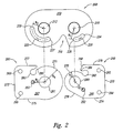
- Figure 2 is an exploded view of a plate, a first hinge member, and a second hinge member of the hinge of Figure 1.
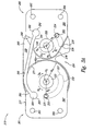
- Figure 3A is a top plan view of an assembly including a resilient member with the plate, the first hinge member, and the second hinge member of Figure 2.
- Figure 3B is a top plan view of an assembly including a first torsion spring attached to a first hinge member and a second torsion spring attached to a second hinge member.
- Figure 4 is a top plan view of first and second adjustable range restrictors.
- Figure 5A is a top plan view of an adjustable range restrictor system.
- Figure 5B is an isometric view of the adjustable range restrictor system of Figure 5A with the first and second adjustable range restrictors removed from a cover plate.
- Figure 6 is an isometric exploded view of a hinge and range restrictor.
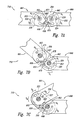
- Figures 7A-7C are top plan views illustrating a hinge with a rocker in accordance with the invention.
- Figure 1 is an isometric view of a knee brace 60 including an upper frame 30, a lower frame 32, and hinges 10 connecting the upper frame 30 to the lower frame 32.
- the upper frame 30 can include at least one strap 20 to wrap around the quadriceps or hamstring, and the lower frame 32 can also include one or more straps.
- the upper and lower frames 30 and 32 can have different configurations and include different configurations of straps.
- the knee brace 60 can also include a flexible, elastic sleeve 62 coupled either directly or indirectly to the upper and lower frames 30 and 32.
- Figure 2 is an exploded view and Figure 3A is a top plan view of one example of the hinge 10.
- the hinge 10 includes a back plate 200, a first hinge member 260, and a second hinge member 261.
- the first hinge member 260 rotatably mounts to the back plate 200 and is configured to attach to the upper frame 30 (Figure 1) to permit the upper frame 30 to pivot about the back plate 200.
- the second hinge member 261 also rotatably mounts to the back plate 200 and is configured to attach to the lower frame 32 ( Figure 1) to permit the lower frame 32 to pivot about the back plate 200 independently of the upper frame 30. Accordingly, the upper and lower frames 30 and 32 pivot independently about two different axes of rotation.
- the first hinge member 260 is a generally flat plate with a front surface 266 and a back surface (not shown) opposite the front surface 266. Between the front surface 266 and the back surface are a top edge 276, a bottom edge 274 and a side edge 272 configured for attachment to a portion of the upper frame 30.
- the first hinge member 260 can include two apertures 262 and 264 proximate the side edge 272 for receiving fasteners (not shown) to connect the upper frame 30 to the first hinge member 260.
- the second hinge member 261 similarly, has a front surface 267 and a back surface (not shown) opposite the front surface 267.
- the second hinge member 261 can also include two apertures 263 and 265 proximate the side edge 273 for receiving fasteners (not shown) to connect the lower frame 32 to the second hinge member 261.
- the first hinge member 260 can be an integral portion of the upper frame 30 and the second hinge member 261 can be an integral portion of the lower frame 32.
- the first and second hinge members 260 and 261 can have different configurations in other examples.
- the first hinge member 260 is pivotally connected to the back plate 200 by a fastener 320.
- the first hinge member 260 rotates relative to the back plate 200 about a first axis of rotation A 1 ( Figure 3A).
- the first hinge member 260 has a pin 252 that projects from the front surface 266 and the back surface.
- the pin 252 can have a different configuration or shape.
- the pin 252 can extend or project from either the front surface 266 or the back surface. The portion of the pin 252 projecting from the back surface is received within an annular slot 220 in the back plate 200.
- the annular slot 220 is accordingly centered about the first axis of rotation A 1 with a centerline at a radius R 1 corresponding to the distance from the first axis of rotation A 1 to the pin 252. Accordingly, as the first hinge member 260 rotates relative to the back plate 200 about the first axis of rotation A 1 , the pin 252 slides in the annular slot 220. A first endpoint 224 and a second endpoint 226 of the slot 220 define the maximum range of motion for the first hinge member 260. Accordingly, the length of the slot 220 determines the pivoting range of the first hinge member 260 relative to the back plate 200. In additional examples, the slot 220 can have different lengths to change the pivoting range of the first hinge member 260. In other examples the position of the slot 220 and the pin 252 can be different, such as the slot 220 can be in the first hinge member 260 and the pin 252 can be attached to the back plate 200.
- the second hinge member 261 is pivotally connected to the back plate 200 by a fastener 322.
- the second hinge member 261 rotates relative to the back plate 200 about a second axis of rotation A 2 ( Figure 3A).
- the second hinge member 261 has a pin 253 that projects from the front surface 267 and the back surface.
- the pin 253 can have a different configuration or shape.
- the pin 253 can extend or project from either the front surface 267 or the back surface, or there can be two separate pins extending from each surface. The portion of the pin 253 projecting from the back surface is received within an annular slot 222 in the back plate 200.
- the annular slot 222 is accordingly centered about the second axis of rotation A 2 with a centerline at a radius R 2 corresponding to the distance from the second axis of rotation A 2 to the pin 253.
- the pin 253 slides in the annular slot 222.
- a first endpoint 225 and a second endpoint 227 of the slot 222 define the maximum range of motion for the second hinge member 261.
- the length of the slot 222 determines the pivoting range of the second hinge member 261 relative to the back plate 200.
- the slot 222 can have a different length to change the pivoting range of the second hinge member 261.
- the position of the slot 222 and the pin 253 can be different, such as the slot 222 can be in the second hinge member 261 and the pin 253 can be attached to the back plate 200.
- the curved edge 270 on the first hinge member 260 is spaced away from the curved edge 271 on the second hinge member by a gap G. Accordingly, the first hinge member 260 and the second hinge member 261 pivot independently about the two different axes of rotation A 1 and A 2 . Because the hinge has two different and independent axes of rotation, it better simulates the natural motion of the knee joint. This is expected to mitigate the sliding of the knee brace down the leg and reduce exerting unnatural forces against the knee joint.
- the back plate 200 has a cutout portion 250.
- the cutout portion 250 allows the first and second hinge members 260 and 261 to rotate through the full pivoting range without the upper and lower frames 30 and 32 ( Figure 1) striking the back plate 200.
- first hinge member 260 and the second hinge member 261 are operatively coupled by a resilient member 300.
- the resilient member 300 has a first end 302 attached to the first hinge member 260 and a second end 304 attached to the second hinge member 26.
- the first end 302 is received within an aperture 282 in the first hinge member 260.
- a channel 284 connects the aperture 282 to an edge 268 and is sized to receive a portion of the resilient member 300.
- the second end 304 of the resilient member is received within an aperture 283 of the second hinge member 261.
- a channel 285 connects the aperture 283 to the edge 277 and is sized to receive a portion of the resilient member 300.
- the first end 302 and the second end 304 of the resilient member 300 are enlarged so that they are not pulled through the smaller channels 284 and 285.
- the first end 302 and the second end 304 of the resilient member 300 have a donut shape with a pin in the center.
- the first end 302 and second end 304 of the resilient member 300 can be clamped or bonded.
- the resilient member 300 is elastic and provides resistance to the hinge members 260 and 261 during flexion.
- urethane can be used; in other examples other materials may be used.
- the resilient member 300 stretches as the first hinge member 260 rotates in a direction D 1 and/or the second hinge member 261 rotates in a direction D 2 .
- the resilient member 300 urges the first hinge member 260 to rotate in a direction D 3 and the second hinge member 261 to rotate in a direction D 4 . Accordingly, when no external force is placed on the first and second hinge members 260 and 261, the pins 252 and 253 are drawn toward the first endpoints 224 and 225 of the slots 220 and 222.
- the resilient member 300 When an external force is applied to the first hinge member 260 causing rotation in the direction D 1 , the resilient member 300 stretches elastically and rides along a curved edge 270 of the first hinge member 260.
- the curved edge 270 has a radius R 3 .
- the curved edge 270 may not have a constant radius.
- the resilient member 300 when an external force is applied to the second hinge member 261 causing rotation in the direction D 2 , the resilient member 300 stretches elastically and rides along a curved edge 271 of the second hinge member 261.
- the curved edge 270 has a radius R 4 that is greater than the radius R 3 .
- the radius R 3 can be equal to or greater than the radius R 4 .
- the resilient member 300 and the radii of the hinge members 260 and 261 operate together to control the rotation of the hinge members 260 and 261.
- R 3 is less than R 4
- the first hinge member 260 rotates in direction D 1 for an arc length before the second hinge member 261 rotates for an arc length in direction D 2 .
- greater external force must be applied to rotate a member with a greater radius in light of the counter force applied by the resilient member 300.
- the first hinge member 260 rotates first because its radius R 3 is less than the radius R 4 of the second hinge member 261.
- the second hinge member 261 will begin to rotate after the pin 252 of the first hinge member 260 has rotated through at least a portion of its range of motion.
- the rotation of one hinge member before the rotation of the other hinge member simulates the natural anatomical motion of the knee joint during extension and flexion.
- a better simulation of the natural motion of the knee joint reduces the movement of the brace down the leg of the user and the tendency of the knee brace to force the knee into unnatural positions.
- Figure 3B is a top plan view of an assembly including a first torsion spring 398 attached to a first hinge member 360 and a second torsion spring 399 attached to a second hinge member 361. Each torsion spring 398 and 399 is also attached to the back plate 200.
- the first torsion spring 398 urges the first hinge member 360 to rotate in the direction D 3 and the second torsion spring 399 urges the second hinge member to rotate in the direction D 4 . Accordingly, when no external force is placed on the first and second hinge members 360 and 361, the pins 252 and 253 are drawn toward the first endpoints 224 and 225 of the slots 220 and 222.
- the torsion springs can have different spring coefficients causing one hinge member to rotate before the other.
- Figure 4 is a top plan view of the hinge 310 of Figure 3A with first and second adjustable range restrictors 402 and 404.
- Figure 5A is a top plan view of an adjustable range restrictor system 406.
- Figure 5B is an isometric view of the adjustable range restrictor system 406 of Figure 5A with the first and second adjustable range restrictors 402 and 404 removed from a housing 540.
- the adjustable range restrictor system 406 allows a user to adjust the pivoting range of the first hinge member 260 and/or the second hinge member 261.
- the fastener 320 is received in an aperture 432 of the first adjustable range restrictor 402 so that the first adjustable range restrictor 402 is positionable about the first axis of rotation A 1 .
- the first adjustable range restrictor 402 has an annular slot 422 extending about the first axis of rotation A 1 with a centerline at the radius R 1 .
- the slot 422 is positioned and sized to receive the pin 252 of the first hinge member 260. Accordingly, when the first hinge member 260 pivots, the pin 252 moves within the slot 422.
- the fastener 322 is received in an aperture 430 of the second adjustable range restrictor 404 so that the second adjustable range restrictor 404 is positionable about the second axis of rotation A 2 .
- the second adjustable range restrictor 404 has an annular slot 420 extending about the second axis of rotation A 2 with a centerline at the radius R 2 .
- the slot 420 is positioned and sized to receive the pin 253 of the second hinge member 261. Accordingly, when the second hinge member 261 pivots, the pin 253 can move within the slot 420.
- the length of the slot 420 is approximately equal to the length of the slot 222
- the length of the slot 422 is approximately equal to the length of the slot 220.
- the slots 420 and 422 can have different lengths.
- the first and second adjustable range restrictors 402 and 404 can be rotated so that their slots 422 and 420 limit the rotation of the first and second hinge members 260 and 261.
- the first adjustable range restrictor 402 is positioned so that the slot 422 is offset from the slot 220 of the first hinge member 260. Consequently, a first endpoint 424 of the slot 422 and the second endpoint 226 of the slot 220 define stops for the pin 252 to limit the rotation of the first hinge member 260 about the first axis of rotation A 1 .
- the first adjustable range restrictor 402 can be rotated further in the direction D 1 to further limit the rotation of the first hinge member 260.
- first adjustable range restrictor 402 can be rotated in the direction D 3 to increase the range of rotation.
- the second adjustable range restrictor 404 can similarly be positioned about the second axis of rotation A 2 so that the slot 420 is offset from the slot 222 of the second hinge member 261 to define stops for the pin 253 that limit the rotation of the second hinge member 261 about the second axis of rotation A 2 .
- the adjustable range restrictors 402 and 404 are held in place by the housing 540.
- the housing 540 has a recess 570 with teeth 550 that engage the teeth 412 and 414 of the first and second adjustable range restrictors 402 and 404.
- the teeth 550 preclude the first and second adjustable range restrictors 402 and 404 from rotating about the first and second axes of rotation A 1 and A 2 .
- the housing 540 can have a lip 560 that snap-fits onto the front plate 400 to lock the first and second range restrictors 402 and 404 in desired positions for limiting the range of motion.
- the first and second adjustable range restrictors 402 and 404 are rotatably adjusted by removing the housing 540, rotating the first and second adjustable range restrictors 402 and 404, and replacing the housing 540.
- the configuration of the teeth 412, 414 and 550 in the illustrated embodiment permits the first and second adjustable range restrictors 402 and 404 to be adjusted in 10-degree increments. In additional examples, the teeth 412, 414 and 550 can be sized and spaced differently.
- the range restrictor system 406 shown in Figures 4-5B can have other configurations.
- other types of devices can be used to restrict the first and second adjustable range restrictors 402 and 404 from rotating about the first and second axes of rotation A 1 and A 2 .
- the front plate 400 could have a projection with teeth that engage the teeth of one or both of the adjustable range restrictors 402 and 404, thus eliminating the need for the housing 540.
- the front plate 400 is similar to the back plate 200, but is positioned on the other side of the hinge member 260 and 261.
- the front plate 400 can have a different configuration, or the hinge may not have the front plate 400.
- the first and second adjustable range restrictors 402 and 404 thus eliminating the need for the housing 540.
- the front plate 400 is similar to the back plate 200, but is positioned on the other side of the hinge member 260 and 261.
- the front plate 400 can have a different configuration, or the hinge may not have the front plate 400.
- the first and second adjustable range restrictors 402 and 404 can be placed proximate to the first and second hinge members 260 and 261, or the adjustable range restrictor system 406 can be placed adjacent to the back surface of the back plate 200.
- the hinge may not have the adjustable range restrictor system 406.
- FIG 6 is an exploded view of the hinge 10 of Figure 1.
- the first and second hinge members 260 and 261 are held between the back plate 200 and the front plate 400 by the fasteners 320 and 322.
- the hinge 10 may have spacers 600, 620, 630 and 632 to assist the first and second hinge members 260 and 261 to rotate more easily between the plates 400 and 200.
- the spacers 600 and 630 each have an aperture 604 through which the fastener 320 is placed, and an aperture 602 through which the first pin 252 is placed.
- the spacers 620 and 632 each have an aperture 624 through which the fastener 322 is placed, and an aperture 622 through which the second pin 253 is placed.
- the spacers 600, 620, 630 and 632 can have different configurations, or the hinge 10 may not have one or more of the spacers 600, 620, 630 and 632.
- the range restrictor system 406 attaches to the front plate 400 as explained above.
- Figure 6 also illustrates the compactness of the hinge 10 and the range restrictor system 406.
- the hinge 10 and the range restrictor system 406 together can have a thickness of between 0.125 inch and 1 inch. In one embodiment, the hinge 10 and the range restrictor system 406 together have a thickness of approximately 0.31 inch.
- the compact size of the hinge 10 and the range restrictor system 406 makes it easier to wear clothes over the knee brace and reduces the potential of having the hinge interfere with the other knee joint during activities.
- FIGS 7A-7C are top plan views illustrating a hinge 710 in accordance with the invention.
- the hinge 710 is similar to the hinge 10 described above, and like reference numbers refer to like components in Figures 1-7C.
- the hinge 710 includes a first hinge member 660 with a first recess 662 and a second hinge member 661 with a second recess 663.
- the first and second hinge members 660 and 661 are pivotally coupled to the back plate 200.
- the pin 252 of the first hinge member 660 is positioned at the first endpoint 224 of the slot 220 in the back plate 200
- the pin 253 of the second hinge member 661 is positioned at the first endpoint 225 of the slot 222 in the back plate 200.
- the hinge 710 also includes a rocker 650 attached to the back plate 200.
- the rocker 650 has a flexible arm 698 and a head 697 positioned between the first hinge member 660 and the second hinge member 661.
- the head 697 When the hinge 710 is in the full-extension position shown in Figure 7A, the head 697 is proximate a curved edge 670 of the first hinge member 660 and at least partially within the second recess 663 of the second hinge member 661. Because the head 697 of the rocker 650 is at least partially within the second recess 663 of the second hinge member 661, the second hinge member 661 is effectively jammed and restricted from movement. Accordingly, a force applied to either hinge member 660 or 661 will cause the first hinge member 660 to pivot in a direction S 1 about the first axis of rotation A 1 .
- the first hinge member 660 has pivoted about the first axis of rotation A 1 to a position where the pin 252 is at the second endpoint 226 of the slot 220 in the back plate 200.
- the first hinge member 660 accordingly cannot pivot further about the first axis of rotation A 1 in the direction S 1 .
- the head 697 of the rocker 650 is received at least partially within the first recess 662 of the first hinge member 660, releasing the bending force on the arm 698. In this position the head 697 is free to move between the two recesses 662 and 663.
- the cam shape of the surface 671 forces the head 697 of the rocker 650 into the recess 662 of the first hinge member 660, effectively jamming and precluding rotation of the first hinge member 660 about the first axis of rotation A 1 .
- the second hinge member 661 has pivoted about the second axis of rotation A 2 to a position where the pin 253 is at the second endpoint 227 of the slot 222 in the back plate 200.
- the second hinge member 661 accordingly cannot pivot further about the second axis of rotation A 2 in the direction S 2 .
- the head 697 of the rocker 650 remains in the first recess 662 of the first hinge member 660 precluding the first hinge member 660 from pivoting about the first axis of rotation A 1 .
- the first hinge member 660 requires a greater force to rotate in a direction S 3 than the force required for the second hinge member 661 to rotate in a direction S 4 . Accordingly, the rocker 650 encourages the second hinge member 661 to pivot in the direction S 4 about the second axis of rotation A 2 before the first hinge member 660 pivots in the direction S 3 about the first axis of rotation A 1 .
- the hinge 710 can have a rocker with a different configuration.
- Figures 7A-7C illustrate the full range of extension ( Figures 7A-B) and flexion ( Figures 7B-C) of the illustrated embodiment.
Landscapes
- Health & Medical Sciences (AREA)
- Public Health (AREA)
- Veterinary Medicine (AREA)
- Engineering & Computer Science (AREA)
- Nursing (AREA)
- Heart & Thoracic Surgery (AREA)
- Vascular Medicine (AREA)
- Life Sciences & Earth Sciences (AREA)
- Animal Behavior & Ethology (AREA)
- Orthopedic Medicine & Surgery (AREA)
- General Health & Medical Sciences (AREA)
- Biomedical Technology (AREA)
- Pivots And Pivotal Connections (AREA)
- Pyridine Compounds (AREA)
- Orthopedics, Nursing, And Contraception (AREA)
- Joining Of Building Structures In Genera (AREA)
- Lighters Containing Fuel (AREA)
- Hinges (AREA)
- Dry Shavers And Clippers (AREA)
- Superstructure Of Vehicle (AREA)
Claims (12)
- Bizentrisches Gelenk (710) zur Verwendung in einer einen Rahmen aufweisenden Stütze mit- einer Platte (200),- einem mit der Platte (200) drehbar gekoppelten, ersten Glied (660), das um eine erste Drehachse (A1) zwischen einer ersten Position und einer zweiten Position drehbar und derart ausgebildet ist, dass es am Rahmen befestigbar ist,- einem mit der Platte (200) drehbar gekoppelten zweiten Glied (661), das um eine von der ersten Drehachse (A1) einen Abstand aufweisende, zweite Drehachse (A2) zwischen einer dritten Position und einer vierten Position drehbar und derart ausgebildet ist, dass es am Rahmen befestigbar ist,- wobei das erste Glied (660) einen ersten Umfang mit einem ersten gebogenen Teil aufweist, der mindestens teilweise um die erste Drehachse (A1) verläuft, und das zweite Glied (661) einen zweiten Umfang mit einem zweiten gebogenen Teil aufweist, der mindestens teilweise um die zweite Drehachse (A2) verläuft,- wobei das Gelenk (710) ferner einen mit der Platte (200) gekoppelten Schwinghebel (650) aufweist und- wobei der Schwinghebel (650) die Drehung des einen Glieds des ersten Glieds (660) und des zweiten Glieds (661) begrenzt, bis sich das andere Glied gedreht hat,dadurch gekennzeichnet, dass- das erste gebogene Teil eine erste Ausnehmung (662) aufweist,- das zweite gebogene Teil eine zweite Ausnehmung (663) aufweist und- der Schwinghebel (650) einen Kopf (697) aufweist, der mindestens teilweise in der ersten Ausnehmung (662) und/oder der zweiten Ausnehmung (663) aufnehmbar ist.
- Gelenk nach Anspruch 1,
dadurch gekennzeichnet,
dass in dem Fall, in dem sich das erste Glied (660) in der ersten Position befindet, sich der Kopf (697) in der Nähe des ersten gebogenen Teils befindet, und dass in dem Fall, in dem sich das erste Glied (660) in der zweiten Position befindet, der Kopf (697) mindestens teilweise in der ersten Ausnehmung aufgenommen ist,
und dass in dem Fall, in dem sich das zweite Glied (661) in der dritten Position befindet, der Kopf (697) mindestens teilweise in der zweiten Ausnehmung aufgenommen ist, und dass In dem Fall, in dem sich das zweite Glied (661) in der vierten Position befindet, sich der Kopf (697) in der Nähe des zweiten gebogenen Teils befindet. - Gelenk nach Anspruch 1 oder 2,
dadurch gekennzeichnet,
dass die Platte (200) einen ersten Schlitz (220) und einen zweiten Schlitz (222) aufweist, dass das erste Glied (660) einen im ersten Schlitz aufgenommenen ersten Stift (252) aufweist und dass das zweite Glied einen im zweiten Schlitz (222) aufgenommenen zweiten Stift (253) aufweist. - Gelenk nach einem der Ansprüche 1 bis 3,
dadurch gekennzeichnet, dass- die Platte (200) einen ersten ringförmigen Schlitz (220) mit einer ersten Länge um die erste Drehachse (A1) und einen zweiten ringförmigen Schlitz (222) mit einer zweiten Länge um die zweite Drehachse (A2) aufweist,- das erste Glied (660) einen im ersten ringförmigen Schlitz (220) aufgenommenen ersten Stift (252) aufweist, der sich im ersten ringförmigen Schlitz (220) bewegt, wenn das erste Glied (660) sich um die erste Drehachse (A1) dreht, und die erste Länge des ersten ringförmigen Schlitzes (220) den Drehbereich des ersten Glieds (660) um die erste Drehachse (A1) begrenzt und- das zweite Glied (661) einen im zweiten ringförmigen Schlitz (220) aufgenommenen zweiten Stift (253) aufweist, der sich im zweiten ringförmigen Schlitz (222) bewegt, wenn das zweite Glied (661) sich um die zweite Drehachse (A2) dreht, und die zweite Länge des zweiten ringförmigen Schlitzes (222) den Drehbereich des zweiten Glieds (660) um die zweite Drehachse (A2) begrenzt - Gelenk nach einem der Ansprüche 1 bis 4, bei dem die Platte (200) einen ersten ringförmigen Schlitz (220) und einen zweiten ringförmigen Schlitz (222) aufweist,
dadurch gekennzeichnet,
dass das Gelenk ferner aufweist;- einen mit der Platte (200) betriebsmäßig gekoppelten, ersten einstellbaren Bereichsbegrenzer (402) mit einem dritten ringförmigen Schlitz (422) und- einen mit der Platte (200) betriebsmäßig gekoppelten, zweiten einstellbaren Bereichsbegrenzer (404) mit einem vierten ringförmigen Schlitz (420)und dass das erste Glied (660) einen im ersten ringförmigen Schlitz (220) und im dritten ringförmigen Schlitz (422) aufgenommenen ersten Stift (252) und das zweite Glied (661) einen im zweiten ringförmigen Schlitz (220) und im vierten ringförmigen Schlitz (420) aufgenommenen zweiten Stift (253) aufweist. - Gelenk nach einem der Ansprüche 2 bis 4,
dadurch gekennzeichnet,
dass das Gelenk ferner aufweist:- einen mit der Platte (200) betriebsmäßig gekoppelten, ersten einstellbaren Bereichsbegrenzer (402) mit einem dritten ringförmigen Schlitz (422),- einen mit der Platte (200) betriebsmäßig gekoppelten, zweiten einstellbaren Bereichsbegrenzer (404) mit einem vierten ringförmigen Schlitz (422),und dass der erste Stift (252) im ersten ringförmigen Schlitz (220) und im dritten ringförmigen Schlitz (422) aufgenommen und der zweite Stift (253) im zweiten ringförmigen Schlitz (222) und im vierten ringförmigen Schlitz (420) aufgenommen ist. - Gelenk nach einem der vorhergehenden Ansprüche,
dadurch gekennzeichnet,
dass es ferner ein flexibles Glied (300) mit einem ersten Ende (302) und einem zweiten Ende (304) aufweist, wobei das erste Ende (302) mit dem ersten Glied (660) und das zweite Ende (304) mit dem zweiten Glied (661) betriebsmäßig gekoppelt ist, und dass in dem Fall, in dem sich das erste Glied (660) In die erste Position dreht, das flexible Glied (300) das erste Glied (660) derart drückt, dass dieses in die erste Position zurückkehrt und/oder in dem Fall, in dem sich das zweite Glied (661) in die vierte Position dreht, das flexible Glied (300) das zweite Glied (661) derart drückt, dass dieses in die dritte Position zurückkehrt. - Gelenk nach einem der Ansprüche 1 bis 6,
dadurch gekennzeichnet,
dass es ferner eine an der Platte (200) und dem ersten Glied (660) befestigte erste Torsionsfeder (398) und eine an der Platte (200) und dem zweiten Glied (661) befestigte zweite Torsionsfeder (399) aufweist. - Gelenk nach Anspruch 8,
dadurch gekennzeichnet,
dass die Torsionsfedern (398, 399) verschiedene Federkoeffizienten aufweisen. - Gelenk nach einem der Ansprüche 1 bis 6,
dadurch gekennzeichnet,
dass es ferner ein flexibles Glied (300) mit einem ersten Endteil (302) und einem zweiten Endteil (304) aufweist, wobei das erste Endteil (302) mit dem ersten Glied (660) und das zweite Endteil (304) mit dem zweiten Glied (661) betriebsmäßig gekoppelt ist, und dass das flexible Glied (300) zwischen einer ersten Länge und einer zweiten Länge ausziehbar ist. - Stütze mit einem Gelenk nach einem der vorhergehenden Ansprüche,
- Stütze nach Anspruch 11,
dadurch gekennzeichnet,
dass sie eine Kniestütze oder eine Ellbogenstütze ist.
Applications Claiming Priority (3)
| Application Number | Priority Date | Filing Date | Title |
|---|---|---|---|
| US77469 | 2002-02-15 | ||
| US10/077,469 US6969363B2 (en) | 2002-02-15 | 2002-02-15 | Bicentric hinge for use in a brace |
| PCT/US2003/003668 WO2003070130A2 (en) | 2002-02-15 | 2003-02-06 | Bicentric hinge for use in a brace |
Publications (2)
| Publication Number | Publication Date |
|---|---|
| EP1490004A1 EP1490004A1 (de) | 2004-12-29 |
| EP1490004B1 true EP1490004B1 (de) | 2007-09-05 |
Family
ID=27660283
Family Applications (1)
| Application Number | Title | Priority Date | Filing Date |
|---|---|---|---|
| EP03742712A Expired - Lifetime EP1490004B1 (de) | 2002-02-15 | 2003-02-06 | Bizentrisches scharnier zur verwendung in einer schiene |
Country Status (8)
| Country | Link |
|---|---|
| US (1) | US6969363B2 (de) |
| EP (1) | EP1490004B1 (de) |
| AT (1) | ATE372098T1 (de) |
| AU (1) | AU2003210897A1 (de) |
| DE (1) | DE60316130T2 (de) |
| DK (1) | DK1490004T3 (de) |
| ES (1) | ES2298536T3 (de) |
| WO (1) | WO2003070130A2 (de) |
Families Citing this family (23)
| Publication number | Priority date | Publication date | Assignee | Title |
|---|---|---|---|---|
| US7488300B2 (en) * | 2002-02-15 | 2009-02-10 | Thusane | Bicentric hinge for use in a brace |
| US7828856B2 (en) * | 2004-09-30 | 2010-11-09 | Brian Bartlett | Leg prosthesis system and method |
| US9895239B2 (en) * | 2005-09-30 | 2018-02-20 | Brian Bartlett | Limb prosthesis system and method |
| US7507215B2 (en) | 2005-07-08 | 2009-03-24 | Jri Development Group, Llc | Orthotic brace |
| US7749182B2 (en) * | 2005-12-13 | 2010-07-06 | 3M Innovative Properties Company | Stay hinge for orthopedic supports and method of using same |
| GB2436799B (en) * | 2006-04-06 | 2009-02-25 | David Allen Seaby | Legbrace/ski armour |
| US20080108922A1 (en) * | 2006-11-02 | 2008-05-08 | Asterisk.Asterisk, Llc | Joint brace with improved adjustable limb extension regulator |
| US7524295B1 (en) * | 2007-06-25 | 2009-04-28 | Ultra Athlete Llc | Convertible ankle brace |
| US7927299B2 (en) * | 2008-01-31 | 2011-04-19 | Krause David A | Knee brace |
| CN102026595B (zh) * | 2008-05-14 | 2013-11-20 | 奥苏尔公司 | 腿支承件 |
| WO2010065098A1 (en) * | 2008-12-03 | 2010-06-10 | Ossur Hf | Orthopedic device having hybrid frame elements |
| US8795212B2 (en) * | 2009-08-07 | 2014-08-05 | Djo, Llc | Hinge brace assembly having a structural outer plate |
| US8894594B2 (en) | 2010-04-06 | 2014-11-25 | Hosso, Inc. | Limb protection device |
| US9044306B2 (en) | 2010-04-06 | 2015-06-02 | Hosso, Inc. | Limb protection device |
| US10314680B2 (en) | 2010-04-06 | 2019-06-11 | Horsepower Technologies Inc. | Limb protection device |
| US9427347B2 (en) | 2010-04-06 | 2016-08-30 | Hosso, Inc. | Limb protection device |
| US8882688B1 (en) | 2010-11-15 | 2014-11-11 | Craig Ancinec | Orthotic joint stabilizing assembly |
| WO2014099739A2 (en) * | 2012-12-18 | 2014-06-26 | Hosso Inc | Limb protection device |
| US10231859B1 (en) | 2014-05-01 | 2019-03-19 | Boston Dynamics, Inc. | Brace system |
| US9687364B2 (en) * | 2014-09-25 | 2017-06-27 | Department Of Biotechnology, Ministry Of Science & Technology | Injection mouldable polymeric composite based passive polycentric knee joint |
| US10085870B2 (en) | 2015-06-22 | 2018-10-02 | Horsepower Technologies Inc. | Joint brace with improved range of motion stop |
| US10070983B2 (en) * | 2015-09-11 | 2018-09-11 | Spring Loaded Technology Incorporated | Hinge for a brace |
| KR102897847B1 (ko) * | 2023-08-23 | 2025-12-10 | 한국생산기술연구원 | 무릎 관절용 웨어러블 장치 |
Citations (1)
| Publication number | Priority date | Publication date | Assignee | Title |
|---|---|---|---|---|
| WO2001066049A2 (en) * | 2000-03-06 | 2001-09-13 | Generation Ii Orthotics, Inc. | Joint for a knee brace incorporating a locking mechanism |
Family Cites Families (62)
| Publication number | Priority date | Publication date | Assignee | Title |
|---|---|---|---|---|
| US2573866A (en) * | 1948-05-14 | 1951-11-06 | Myron W Nusbaum | Leg brace |
| US4323059A (en) * | 1979-04-19 | 1982-04-06 | Andre Rambert | Articulated splint for a knee joint |
| US4407276A (en) * | 1981-01-22 | 1983-10-04 | Medical Designs, Inc. | Brace for articulated limbs |
| US4337764A (en) * | 1981-03-02 | 1982-07-06 | United States Manufacturing Company | Adjustable motion brace |
| US4489718A (en) * | 1983-03-08 | 1984-12-25 | Medical Designs, Inc. | Knee brace hinge |
| US4493316A (en) * | 1983-03-10 | 1985-01-15 | Donjoy, Inc. | Articulating knee stabilizer |
| US4502472A (en) * | 1983-09-12 | 1985-03-05 | Pansiera Timothy T | Hinge means for orthopedic brace |
| US4620532A (en) * | 1983-09-26 | 1986-11-04 | Lenox Hill Brace Shop, Inc. | Adjustment device for an articulated joint brace |
| US4520802A (en) * | 1983-09-30 | 1985-06-04 | Mercer James D | Bi-axial orthotic device |
| US4599998A (en) * | 1984-06-01 | 1986-07-15 | Castillo James D | Adjustable polycentric orthopedic appliance hinge |
| US4633867A (en) * | 1984-06-27 | 1987-01-06 | James H. Kausek | Knee brace for control of ligament instability |
| US4697583A (en) * | 1985-01-29 | 1987-10-06 | Don Joy Orthopedic, Inc. | Four-point anterior cruciate ligament brace |
| US4938207A (en) * | 1986-10-20 | 1990-07-03 | Alexander C. Vargo | Knee brace having plurality of fluid filled chambers surrounding knee |
| GB2208065B (en) * | 1987-02-18 | 1991-10-09 | David Ernest Young | Bi-pivotal orthopaedic and orthotic hinge with improved adjustment means |
| US5018514A (en) * | 1987-06-11 | 1991-05-28 | Brace Technologies, Inc. | Knee brace |
| US4886054A (en) * | 1987-06-29 | 1989-12-12 | Innovation Sports, Inc. | Knee brace with cammed stop lever |
| GB8802288D0 (en) * | 1988-02-02 | 1988-03-02 | Protectair Ltd | Improved adjustment means for bi-pivotal orthopaedic & orthotichings |
| US4802467A (en) * | 1988-05-09 | 1989-02-07 | Timothy Pansiera | Bi-centric knee joint support |
| US4865024A (en) * | 1988-10-21 | 1989-09-12 | Hensley Dvid E | Extension deceleration orthosis |
| GB2227520B (en) * | 1988-10-26 | 1992-08-12 | Protectair Ltd | Adjustable hinge device |
| US4928676A (en) * | 1989-02-27 | 1990-05-29 | Timothy Pansiera | Knee brace with flexible secondary joint |
| US4961416A (en) * | 1989-06-12 | 1990-10-09 | Orthopedic Systems, Inc. | Knee brace |
| EP0413424A1 (de) * | 1989-08-14 | 1991-02-20 | Protectair Limited | Orthopädisches doppelschwenkbares Gelenk und Schwenksteuersystem dafÀ¼r |
| US4986264A (en) * | 1989-09-29 | 1991-01-22 | Miller Marion E | Knee brace |
| US5749840A (en) * | 1989-12-07 | 1998-05-12 | Ultraflex Systems, Inc. | Dynamic splint |
| US5658241A (en) * | 1990-02-09 | 1997-08-19 | Ultraflex Systems, Inc. | Multi-functional dynamic splint |
| US5060640A (en) * | 1990-03-14 | 1991-10-29 | Becker Orthopedic Appliance Company | Knee brace |
| CA2089658A1 (en) | 1990-08-17 | 1992-02-18 | E. Paul France | Patella-femoral brace |
| US5259832A (en) * | 1991-03-06 | 1993-11-09 | Jeffrey H. Townsend | Multiaxis controlled motion knee brace with a four bar joint and method for producing same |
| US5230697A (en) * | 1991-05-02 | 1993-07-27 | Innovation Sports, Inc. | Knee brace |
| US5462517A (en) * | 1992-06-26 | 1995-10-31 | D'mannco, Inc. | Knee brace having an inflatable bladder support |
| US5415625A (en) | 1992-07-01 | 1995-05-16 | Smith & Nephew Donjoy, Inc. | Orthopedic brace having a system of alternately inflatable or deflatable pneumatic pads for adjustable fitting of the brace to the body |
| US5520622A (en) | 1992-07-01 | 1996-05-28 | Smith & Nephew Donjoy Inc. | Orthopedic brace having a pneumatic pad and associated pump |
| EP0611093A3 (de) * | 1993-02-05 | 1994-08-31 | Stephen Hutchins | Knieorthese |
| GB9305748D0 (en) * | 1993-03-19 | 1993-05-05 | Steeper Hugh Ltd | An orthotic caliper |
| US5399154A (en) * | 1993-06-30 | 1995-03-21 | Empi, Inc. | Constant torque range-of-motion splint |
| US5792084A (en) * | 1993-08-10 | 1998-08-11 | Smith & Nephew, Inc. | Knee brace having an inflatable pad circumscribing the patella |
| US5356370A (en) * | 1993-09-09 | 1994-10-18 | Generation Ii Orthotics Inc. | Antifriction mechanical joint for an orthopedic knee brace |
| US5437611A (en) * | 1993-12-01 | 1995-08-01 | Orthotic Rehabilitation Products, Inc. | Dynamic brace joint |
| US5472412A (en) * | 1994-04-05 | 1995-12-05 | Mauch Laboratories, Inc. | Limb brace with adjustable hydraulic resistance unit |
| US5460599A (en) * | 1994-05-26 | 1995-10-24 | Orthomerica Products, Inc. | Orthopedic hinge assembly for a leg brace |
| US5443444A (en) * | 1994-07-19 | 1995-08-22 | Professional Care Products Incorporated | Orthopaedic polycentric hinge |
| US5586970A (en) * | 1995-01-23 | 1996-12-24 | Orthopedic Technology, Inc. | Articulating adjustabe condylar pad for knee brace |
| US5662596A (en) * | 1995-08-30 | 1997-09-02 | Young; David Ernest | True bi-pivotal orthopedic and orthotic hinge with incremental motion control |
| US5643185A (en) * | 1995-10-31 | 1997-07-01 | Watson; Randy C. | Knee and elbow joint brace |
| US5776086A (en) * | 1996-01-11 | 1998-07-07 | Pansiera; Timothy T. | Hinge system for an orthopedic brace |
| US5772618A (en) * | 1996-05-31 | 1998-06-30 | Breg, Inc. | Hinge for an orthopedic brace |
| US5891061A (en) * | 1997-02-20 | 1999-04-06 | Jace Systems, Inc. | Brace for applying a dynamic force to a jointed limb |
| GB9704586D0 (en) * | 1997-03-05 | 1997-04-23 | Doyle Kelvin C | Hinge mechanism for a limb protector |
| US6540707B1 (en) * | 1997-03-24 | 2003-04-01 | Izex Technologies, Inc. | Orthoses |
| US5921946A (en) | 1997-10-22 | 1999-07-13 | Smith & Nephew, Inc. | Joint brace hinges |
| US5857989A (en) * | 1997-11-24 | 1999-01-12 | Smith, Iii; Kirby | Dynamic orthopedic knee brace assembly |
| US6074355A (en) * | 1998-02-06 | 2000-06-13 | Bartlett; Edwin Clary | Knee brace |
| US6402711B1 (en) * | 1999-08-10 | 2002-06-11 | Richard S. Nauert | Knee brace operating hinge |
| DE29914375U1 (de) * | 1999-08-17 | 1999-11-25 | medi Bayreuth Weihermüller und Voigtmann GmbH & Co. KG, 95448 Bayreuth | Orthesengelenk |
| EP1088534A3 (de) | 1999-09-28 | 2001-04-25 | Depuy Orthopaedics, Inc. | Einstellbare Gelenkorthese mit linear aktivierbaren Anschlägen |
| US6402713B1 (en) * | 1999-10-18 | 2002-06-11 | Brian P. Doyle | Knee orthosis and hinge joint |
| WO2001089434A1 (en) * | 2000-05-23 | 2001-11-29 | Electro-Biology, Inc. | Orthopaedic brace assembly |
| AU2001271804A1 (en) | 2000-06-30 | 2002-01-14 | Dj Orthopedics, Llc | Orthopaedic brace having a range of motion hinge with radially actuated stops |
| US6387066B1 (en) * | 2000-10-10 | 2002-05-14 | Joseph Whiteside | Self-aligning adjustable orthopedic joint brace |
| US6702771B1 (en) * | 2001-03-01 | 2004-03-09 | Amei Technologies, Inc. | Canting mechanism for an ambulatory support device |
| US6752775B2 (en) * | 2002-02-11 | 2004-06-22 | Dj Orthopedics, Llc | Brace hinge with telescoping condyle pad |
-
2002
- 2002-02-15 US US10/077,469 patent/US6969363B2/en not_active Expired - Fee Related
-
2003
- 2003-02-06 EP EP03742712A patent/EP1490004B1/de not_active Expired - Lifetime
- 2003-02-06 ES ES03742712T patent/ES2298536T3/es not_active Expired - Lifetime
- 2003-02-06 AT AT03742712T patent/ATE372098T1/de active
- 2003-02-06 DE DE60316130T patent/DE60316130T2/de not_active Expired - Lifetime
- 2003-02-06 DK DK03742712T patent/DK1490004T3/da active
- 2003-02-06 AU AU2003210897A patent/AU2003210897A1/en not_active Abandoned
- 2003-02-06 WO PCT/US2003/003668 patent/WO2003070130A2/en not_active Ceased
Patent Citations (1)
| Publication number | Priority date | Publication date | Assignee | Title |
|---|---|---|---|---|
| WO2001066049A2 (en) * | 2000-03-06 | 2001-09-13 | Generation Ii Orthotics, Inc. | Joint for a knee brace incorporating a locking mechanism |
Also Published As
| Publication number | Publication date |
|---|---|
| EP1490004A1 (de) | 2004-12-29 |
| WO2003070130A2 (en) | 2003-08-28 |
| ATE372098T1 (de) | 2007-09-15 |
| DK1490004T3 (da) | 2008-01-07 |
| US6969363B2 (en) | 2005-11-29 |
| DE60316130T2 (de) | 2008-05-29 |
| AU2003210897A1 (en) | 2003-09-09 |
| DE60316130D1 (de) | 2007-10-18 |
| ES2298536T3 (es) | 2008-05-16 |
| US20030153853A1 (en) | 2003-08-14 |
Similar Documents
| Publication | Publication Date | Title |
|---|---|---|
| EP1490004B1 (de) | Bizentrisches scharnier zur verwendung in einer schiene | |
| EP0382976B1 (de) | Knieorthese | |
| EP1750626B1 (de) | Bizentrisches scharnier zur verwendung in einer schiene | |
| EP0454186B1 (de) | Gelenkverbindung für orthopädische Kniestütze | |
| US7192407B2 (en) | Motion controlling hinge for orthopedic brace | |
| US4955369A (en) | Dynamically shiftable counter shear force knee brace | |
| US7811242B2 (en) | Motion controlling hinge for orthopedic brace | |
| CA1190820A (en) | Corrective and protective knee brace | |
| EP1703874B1 (de) | Kniestützscharniere mit adaptiver bewegung | |
| US6971996B2 (en) | Power packs for use with bicentric hinges | |
| CN114072108B (zh) | 线缆支具系统 | |
| CA2563915A1 (en) | Knee brace and hinge mechanism for knee brace |
Legal Events
| Date | Code | Title | Description |
|---|---|---|---|
| PUAI | Public reference made under article 153(3) epc to a published international application that has entered the european phase |
Free format text: ORIGINAL CODE: 0009012 |
|
| 17P | Request for examination filed |
Effective date: 20040915 |
|
| AK | Designated contracting states |
Kind code of ref document: A1 Designated state(s): AT BE BG CH CY CZ DE DK EE ES FI FR GB GR HU IE IT LI LU MC NL PT SE SI SK TR |
|
| AX | Request for extension of the european patent |
Extension state: AL LT LV MK RO |
|
| 17Q | First examination report despatched |
Effective date: 20050120 |
|
| GRAP | Despatch of communication of intention to grant a patent |
Free format text: ORIGINAL CODE: EPIDOSNIGR1 |
|
| GRAS | Grant fee paid |
Free format text: ORIGINAL CODE: EPIDOSNIGR3 |
|
| GRAA | (expected) grant |
Free format text: ORIGINAL CODE: 0009210 |
|
| AK | Designated contracting states |
Kind code of ref document: B1 Designated state(s): AT BE BG CH CY CZ DE DK EE ES FI FR GB GR HU IE IT LI LU MC NL PT SE SI SK TR |
|
| REG | Reference to a national code |
Ref country code: GB Ref legal event code: FG4D |
|
| REG | Reference to a national code |
Ref country code: CH Ref legal event code: EP |
|
| REF | Corresponds to: |
Ref document number: 60316130 Country of ref document: DE Date of ref document: 20071018 Kind code of ref document: P |
|
| REG | Reference to a national code |
Ref country code: IE Ref legal event code: FG4D |
|
| REG | Reference to a national code |
Ref country code: SE Ref legal event code: TRGR |
|
| REG | Reference to a national code |
Ref country code: DK Ref legal event code: T3 |
|
| PG25 | Lapsed in a contracting state [announced via postgrant information from national office to epo] |
Ref country code: FI Free format text: LAPSE BECAUSE OF FAILURE TO SUBMIT A TRANSLATION OF THE DESCRIPTION OR TO PAY THE FEE WITHIN THE PRESCRIBED TIME-LIMIT Effective date: 20070905 |
|
| PG25 | Lapsed in a contracting state [announced via postgrant information from national office to epo] |
Ref country code: GR Free format text: LAPSE BECAUSE OF FAILURE TO SUBMIT A TRANSLATION OF THE DESCRIPTION OR TO PAY THE FEE WITHIN THE PRESCRIBED TIME-LIMIT Effective date: 20071206 |
|
| EN | Fr: translation not filed | ||
| REG | Reference to a national code |
Ref country code: CH Ref legal event code: NV Representative=s name: PATENTANWAELTE SCHAAD, BALASS, MENZL & PARTNER AG |
|
| REG | Reference to a national code |
Ref country code: ES Ref legal event code: FG2A Ref document number: 2298536 Country of ref document: ES Kind code of ref document: T3 |
|
| PG25 | Lapsed in a contracting state [announced via postgrant information from national office to epo] |
Ref country code: PT Free format text: LAPSE BECAUSE OF FAILURE TO SUBMIT A TRANSLATION OF THE DESCRIPTION OR TO PAY THE FEE WITHIN THE PRESCRIBED TIME-LIMIT Effective date: 20080206 |
|
| PLBE | No opposition filed within time limit |
Free format text: ORIGINAL CODE: 0009261 |
|
| STAA | Information on the status of an ep patent application or granted ep patent |
Free format text: STATUS: NO OPPOSITION FILED WITHIN TIME LIMIT |
|
| ET | Fr: translation filed | ||
| REG | Reference to a national code |
Ref country code: FR Ref legal event code: EERR Free format text: CORRECTION DE BOPI 08/18 - BREVETS EUROPEENS DONT LA TRADUCTION N A PAS ETE REMISE A L INPI. IL Y A LIEU DE SUPPRIMER : LA MENTION DE LA NON-REMISE. LA REMISE DE LA TRADUCTION EST PUBLIEE DANS LE PRESENT BOPI. |
|
| 26N | No opposition filed |
Effective date: 20080606 |
|
| PG25 | Lapsed in a contracting state [announced via postgrant information from national office to epo] |
Ref country code: FR Free format text: LAPSE BECAUSE OF FAILURE TO SUBMIT A TRANSLATION OF THE DESCRIPTION OR TO PAY THE FEE WITHIN THE PRESCRIBED TIME-LIMIT Effective date: 20080502 |
|
| PG25 | Lapsed in a contracting state [announced via postgrant information from national office to epo] |
Ref country code: MC Free format text: LAPSE BECAUSE OF NON-PAYMENT OF DUE FEES Effective date: 20080228 |
|
| PG25 | Lapsed in a contracting state [announced via postgrant information from national office to epo] |
Ref country code: EE Free format text: LAPSE BECAUSE OF FAILURE TO SUBMIT A TRANSLATION OF THE DESCRIPTION OR TO PAY THE FEE WITHIN THE PRESCRIBED TIME-LIMIT Effective date: 20070905 Ref country code: IE Free format text: LAPSE BECAUSE OF NON-PAYMENT OF DUE FEES Effective date: 20080206 |
|
| PG25 | Lapsed in a contracting state [announced via postgrant information from national office to epo] |
Ref country code: SI Free format text: LAPSE BECAUSE OF FAILURE TO SUBMIT A TRANSLATION OF THE DESCRIPTION OR TO PAY THE FEE WITHIN THE PRESCRIBED TIME-LIMIT Effective date: 20070905 |
|
| PG25 | Lapsed in a contracting state [announced via postgrant information from national office to epo] |
Ref country code: CY Free format text: LAPSE BECAUSE OF FAILURE TO SUBMIT A TRANSLATION OF THE DESCRIPTION OR TO PAY THE FEE WITHIN THE PRESCRIBED TIME-LIMIT Effective date: 20070905 |
|
| PG25 | Lapsed in a contracting state [announced via postgrant information from national office to epo] |
Ref country code: BG Free format text: LAPSE BECAUSE OF FAILURE TO SUBMIT A TRANSLATION OF THE DESCRIPTION OR TO PAY THE FEE WITHIN THE PRESCRIBED TIME-LIMIT Effective date: 20071205 |
|
| PG25 | Lapsed in a contracting state [announced via postgrant information from national office to epo] |
Ref country code: HU Free format text: LAPSE BECAUSE OF FAILURE TO SUBMIT A TRANSLATION OF THE DESCRIPTION OR TO PAY THE FEE WITHIN THE PRESCRIBED TIME-LIMIT Effective date: 20080306 |
|
| PG25 | Lapsed in a contracting state [announced via postgrant information from national office to epo] |
Ref country code: TR Free format text: LAPSE BECAUSE OF FAILURE TO SUBMIT A TRANSLATION OF THE DESCRIPTION OR TO PAY THE FEE WITHIN THE PRESCRIBED TIME-LIMIT Effective date: 20070905 |
|
| PGFP | Annual fee paid to national office [announced via postgrant information from national office to epo] |
Ref country code: LU Payment date: 20110120 Year of fee payment: 9 |
|
| PGFP | Annual fee paid to national office [announced via postgrant information from national office to epo] |
Ref country code: GB Payment date: 20140627 Year of fee payment: 12 |
|
| PGFP | Annual fee paid to national office [announced via postgrant information from national office to epo] |
Ref country code: AT Payment date: 20140627 Year of fee payment: 12 |
|
| PGFP | Annual fee paid to national office [announced via postgrant information from national office to epo] |
Ref country code: NL Payment date: 20140716 Year of fee payment: 12 Ref country code: DK Payment date: 20140722 Year of fee payment: 12 Ref country code: CH Payment date: 20140715 Year of fee payment: 12 Ref country code: DE Payment date: 20140711 Year of fee payment: 12 |
|
| PGFP | Annual fee paid to national office [announced via postgrant information from national office to epo] |
Ref country code: SE Payment date: 20140717 Year of fee payment: 12 Ref country code: FR Payment date: 20140626 Year of fee payment: 12 Ref country code: ES Payment date: 20140725 Year of fee payment: 12 |
|
| PGFP | Annual fee paid to national office [announced via postgrant information from national office to epo] |
Ref country code: IT Payment date: 20140716 Year of fee payment: 12 |
|
| PGFP | Annual fee paid to national office [announced via postgrant information from national office to epo] |
Ref country code: BE Payment date: 20140730 Year of fee payment: 12 |
|
| PGFP | Annual fee paid to national office [announced via postgrant information from national office to epo] |
Ref country code: CZ Payment date: 20150217 Year of fee payment: 13 Ref country code: SK Payment date: 20150216 Year of fee payment: 13 |
|
| PG25 | Lapsed in a contracting state [announced via postgrant information from national office to epo] |
Ref country code: BE Free format text: LAPSE BECAUSE OF NON-PAYMENT OF DUE FEES Effective date: 20150228 |
|
| PG25 | Lapsed in a contracting state [announced via postgrant information from national office to epo] |
Ref country code: LU Free format text: LAPSE BECAUSE OF NON-PAYMENT OF DUE FEES Effective date: 20130206 |
|
| REG | Reference to a national code |
Ref country code: DE Ref legal event code: R119 Ref document number: 60316130 Country of ref document: DE |
|
| REG | Reference to a national code |
Ref country code: NL Ref legal event code: V1 Effective date: 20150901 |
|
| REG | Reference to a national code |
Ref country code: DK Ref legal event code: EBP Effective date: 20150228 |
|
| REG | Reference to a national code |
Ref country code: SE Ref legal event code: EUG |
|
| PG25 | Lapsed in a contracting state [announced via postgrant information from national office to epo] |
Ref country code: NL Free format text: LAPSE BECAUSE OF NON-PAYMENT OF DUE FEES Effective date: 20150901 |
|
| REG | Reference to a national code |
Ref country code: CH Ref legal event code: PL |
|
| REG | Reference to a national code |
Ref country code: AT Ref legal event code: MM01 Ref document number: 372098 Country of ref document: AT Kind code of ref document: T Effective date: 20150206 |
|
| GBPC | Gb: european patent ceased through non-payment of renewal fee |
Effective date: 20150206 |
|
| PG25 | Lapsed in a contracting state [announced via postgrant information from national office to epo] |
Ref country code: LI Free format text: LAPSE BECAUSE OF NON-PAYMENT OF DUE FEES Effective date: 20150228 Ref country code: CH Free format text: LAPSE BECAUSE OF NON-PAYMENT OF DUE FEES Effective date: 20150228 |
|
| REG | Reference to a national code |
Ref country code: FR Ref legal event code: ST Effective date: 20151030 |
|
| PG25 | Lapsed in a contracting state [announced via postgrant information from national office to epo] |
Ref country code: SE Free format text: LAPSE BECAUSE OF NON-PAYMENT OF DUE FEES Effective date: 20150207 Ref country code: AT Free format text: LAPSE BECAUSE OF NON-PAYMENT OF DUE FEES Effective date: 20150206 |
|
| PG25 | Lapsed in a contracting state [announced via postgrant information from national office to epo] |
Ref country code: IT Free format text: LAPSE BECAUSE OF NON-PAYMENT OF DUE FEES Effective date: 20150206 |
|
| PG25 | Lapsed in a contracting state [announced via postgrant information from national office to epo] |
Ref country code: DK Free format text: LAPSE BECAUSE OF NON-PAYMENT OF DUE FEES Effective date: 20150228 Ref country code: DE Free format text: LAPSE BECAUSE OF NON-PAYMENT OF DUE FEES Effective date: 20150901 Ref country code: GB Free format text: LAPSE BECAUSE OF NON-PAYMENT OF DUE FEES Effective date: 20150206 |
|
| PG25 | Lapsed in a contracting state [announced via postgrant information from national office to epo] |
Ref country code: FR Free format text: LAPSE BECAUSE OF NON-PAYMENT OF DUE FEES Effective date: 20150302 |
|
| REG | Reference to a national code |
Ref country code: ES Ref legal event code: FD2A Effective date: 20160531 |
|
| PG25 | Lapsed in a contracting state [announced via postgrant information from national office to epo] |
Ref country code: ES Free format text: LAPSE BECAUSE OF NON-PAYMENT OF DUE FEES Effective date: 20150207 |
|
| REG | Reference to a national code |
Ref country code: SK Ref legal event code: MM4A Ref document number: E 3344 Country of ref document: SK Effective date: 20160206 |
|
| PG25 | Lapsed in a contracting state [announced via postgrant information from national office to epo] |
Ref country code: CZ Free format text: LAPSE BECAUSE OF NON-PAYMENT OF DUE FEES Effective date: 20160206 Ref country code: SK Free format text: LAPSE BECAUSE OF NON-PAYMENT OF DUE FEES Effective date: 20160206 |