EP1489900B1 - Device and method for driving animals in an oblong corridor section - Google Patents
Device and method for driving animals in an oblong corridor section Download PDFInfo
- Publication number
- EP1489900B1 EP1489900B1 EP03744769A EP03744769A EP1489900B1 EP 1489900 B1 EP1489900 B1 EP 1489900B1 EP 03744769 A EP03744769 A EP 03744769A EP 03744769 A EP03744769 A EP 03744769A EP 1489900 B1 EP1489900 B1 EP 1489900B1
- Authority
- EP
- European Patent Office
- Prior art keywords
- gate
- section
- corridor
- driving
- corridor section
- Prior art date
- Legal status (The legal status is an assumption and is not a legal conclusion. Google has not performed a legal analysis and makes no representation as to the accuracy of the status listed.)
- Expired - Lifetime
Links
Images

Classifications
-
- A—HUMAN NECESSITIES
- A01—AGRICULTURE; FORESTRY; ANIMAL HUSBANDRY; HUNTING; TRAPPING; FISHING
- A01K—ANIMAL HUSBANDRY; AVICULTURE; APICULTURE; PISCICULTURE; FISHING; REARING OR BREEDING ANIMALS, NOT OTHERWISE PROVIDED FOR; NEW BREEDS OF ANIMALS
- A01K1/00—Housing animals; Equipment therefor
- A01K1/0005—Stable partitions
- A01K1/0017—Gates, doors
- A01K1/0029—Crowding gates or barriers
Definitions
- the present invention relates to a device and a method for driving animals in an oblong corridor section by means of a driving gate, which can be moved from one end of the corridor section to the other.
- a travelling elevating gate is a device that runs on rails placed on the topside of the side walls of the driving corridor and has an arrangement to lower a transverse gate into the corridor section between its side walls.
- a drawback by these gates is that animals, which are situated behind the travelling elevating gate, can become anxious when the travelling elevating gate is returning towards them or over them with the gate elevated.
- Such a pate is disclosed in US-A-5009191 .
- Group wise stunning of slaughter pigs in CO 2 has gained a footing in slaughterhouses in recent years because of the lenient handling of the animals.
- a flock of animals is driven from the pen area of the slaughterhouse into a corridor in which the flock is divided into groups of a size, which corresponds to the box size of the stunning apparatus.
- the groups are driven one by one into the boxes of the stunning apparatus. It is essential that the animals remain relatively calm in these processes before they are stunned.
- the device should have a sturdy construction so that it will withstand any violent action from the animals.
- the device according to the invention is characterized in that it comprises a first transport arrangement to move the driving gate in the longitudinal direction of the corridor section, from a first position at one end of the section to a second position at the other end, and to move the gate in the opposite direction after it has been brought outside the corridor section, from a position which is opposite the second position in the corridor section to a position which is opposite the first position in the corridor section, which first arrangement comprises a displaceable mounting part which can be moved in the longitudinal direction of the section over a distance corresponding to the distance between the first position and the second position of the gate, and that it comprises a second transport arrangement to draw the gate sideways out from the corridor section in the plane of the gate from the second position in the corridor section and to push the gate sideways into the corridor section in the plane of the gate from the position which is opposite the first position in the corridor section, which second arrangement comprises a second displaceable mounting part, to which the gate is fastened, and which can be moved transversely to the longitudinal direction of the section over a distance corresponding to at least
- a feature of the device according to the invention is that the driving gate is returned outside the driving corridor with the animals, so that the animals remain calm, as they do not pay attention to the gate during its returning.
- the method according to the invention for driving animals in an oblong corridor section by means of a driving gate, which can be moved from one end to the other of the corridor section, is characterized in
- the device and method according to the invention are used especially for handling of slaughter pigs and sheep (incl. lambs), e.g. for driving these forwards in a driving corridor or in connection with division of a flock of animals of e.g. 15 individuals into groups of 7-8 or 5 animals, and driving-forwards of the groups to a CO 2 -apparatus for group wise stunning.
- the device and method can also be used for handling of cattle, whereby as few as one individual can be handled at a time by animals weighing several hundred kg, as it may be appropriate to handle such big animals one by one when they are to be driven forwards and e.g. stunned in a stunning apparatus, but of course several heads of cattle can also be handled at a time.
- the stunning apparatus can be a CO 2 -apparatus, an electric stunning apparatus or a shooting box.
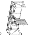
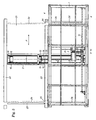
- the device in Figs. 1-4 comprises a rack 1, in which is mounted a first transport arrangement to move a driving gate 2 in a direction transversely to the plane of the gate, and a second transport arrangement to move the gate horizontally in the plane of the gate.
- the device is placed on the outside of a driving corridor for slaughter pigs as shown in Figs. 3-4 .
- the transport arrangement to move the gate transversely to the plane of the gate comprises two guide rails 3 with I-profile.
- the rails are mounted on the underside of two longitudinal girders 4.
- Four ball guides 5, which grip the profile, can be moved along the guide rails 3 and are fastened in separate corners of a first mounting frame 6.
- the mounting frame is provided with a bracket 7 for a motor 8 and a bearing 9, in which a spindle nut 10 can be turned by means of a toothed belt 11, which is connected to the shaft of the motor.
- the spindle nut 10 has an internal thread, which engages with a external thread on a longitudinal spindle 12, which is fastened in either end to the rack 1.
- the second transport arrangement is mounted on the underside of the frame 6 and comprises a second frame 13, which is fastened to the frame 6.
- the rails have been turned 90°, so that their cross section has the shape of a lying "I”.
- On the rails run four ball guides 15 of the same construction as the ball guides 5.
- the guides are connected with each other in pairs by means of transverses 16.
- the transverses have a flange 17 to one side, on which the gate 2 is fastened, so that the gate connects the two transverses.
- One of the transverses 16 has a fixed spindle nut 18 with internal thread.
- the thread co-operates with the external thread on a spindle 19, which is movably mounted in a bearing in the opposite end of the nut 18 and can be turned by means of a motor which is fastened to the second frame 13, a gear wheel 20 on one end of the spindle being actuated by a toothed belt which is driven by the motor.
- the motor turns the spindle, the ball guides 15 with the transverses 16 and gate 2 are displaced in the longitudinal direction of the frame 13, i.e. horizontally in the plane of the gate.
- the device comprises a control unit, which determines the pattern of movement of the gate by activation of one or the other transport arrangement, respectively.
- the device is designed to move the gate in a rectangular pattern, seen from above, i.e. only one transport arrangement is activated at a time.
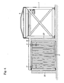
- the device is designed to co-operate with a section 21 of a driving corridor with side walls 22 and two sliding gates 23 and 24, of which the latter is mounted in the rack 1.
- the gate 2 of the device is moved into the section 21 in front of a closed sliding gate 23 through a gap 25 in one side wall of the corridor section.
- the gate 2 is then moved in the direction of the arrow P to a position by the sliding gate 24, driving animals in the section in front of it. It is returned to a position outside the driving corridor through a second gap 26 in the wall, and finally the gate is returned to the starting position.
- the device can e.g. be used in connection with division of a flock of animals into groups, which are to be transferred to a stunning apparatus for group wise stunning.
- a stunning apparatus for group wise stunning.
- PA 2002 00465 "Arrangement and method for division of animals into groups and transfer of groups of animals to stunning apparatus" (Slagteriernes Forskningsinstitut) the design and the functioning of a division system is described in further detail.
- the present device can be part of said system. Some of the functions of the system are described below in connection with fig. 3 .
- a flock of animals of approx. 15 slaughter pigs are driven into a driving corridor and from there into a corridor area to the left of the sliding gate 23, which is closed, if the corridor section 21 is not ready to receive animals.
- the sliding gate 23 is opened partially, to allow one animal at a time to pass into the section.
- the animals are driven forwards and into the corridor section by means of a travelling elevating gate in the corridor area to the left of the sliding gate 23.
- the travelling sliding gate is moved from a position 2a to a position 2b inside the driving corridor by means of the second transport arrangement.
- the sliding gate 24 will be opened and the travelling sliding gate 2 is moved forwards in the corridor section 21 by means of the first transport arrangement, causing the group of animals to walk/be driven into the area to the right of the sliding gate 24.
- the travelling sliding gate stops immediately by the sliding gate 24 in position 2c.
- the sliding gate 24 is closed and the travelling sliding gate 2 is moved, by means of the second transport arrangement, to a position 2d outside the driving corridor and further returned to the position 2a again by means of the first transport arrangement. From the area to the right of the sliding gate 24 the group of animals is driven by means of a movable wall into a stunning apparatus for group wise stunning.
- the sliding gate 23 can be opened completely, so that the group of the remaining animals in the area to the left of the sliding gate 23 can walk into the corridor section 21 as the travelling sliding gate makes this available by the movement from position 2b to position 2c.
- the travelling elevating gate in the corridor to the left of the gate 23 is started again, so that the animals are driven all the way into the corridor section 21.
- the travelling elevating gate stops close to the sliding gate 23, which is closed, whereby the remaining animals has been isolated in the section 21.
- the travelling elevating gate is returned in the corridor area to the left of the gate 23 in order to drive forwards a new flock of animals towards the section 21.
- the gate 2 is pushed into the corridor section behind the isolated group of animals in the section 21 to position 2b.
- the gate 24 will be opened and the gate 2 is moved forwards towards position 2c, so that the animals are driven into the area.
- the sliding gate 24 will be closed and the gate 2 is moved out of the driving corridor to position 2d and from there to position 2a.
- the processes can then be repeated with a new flock of animals, which have been driven into the area to the left of the gate 23, and which can already start walking into the section 21 when the driving gate begins to drive the last animals from the first flock into the area to the right of the gate 24.
Landscapes
- Life Sciences & Earth Sciences (AREA)
- Environmental Sciences (AREA)
- Zoology (AREA)
- Animal Husbandry (AREA)
- Biodiversity & Conservation Biology (AREA)
- Housing For Livestock And Birds (AREA)
- Power-Operated Mechanisms For Wings (AREA)
- Feeding And Watering For Cattle Raising And Animal Husbandry (AREA)
- Catching Or Destruction (AREA)
Applications Claiming Priority (3)
| Application Number | Priority Date | Filing Date | Title |
|---|---|---|---|
| DK200200466 | 2002-03-27 | ||
| DK200200466A DK174938B1 (da) | 2002-03-27 | 2002-03-27 | Udstyr, drivgang og fremgangsmåde til fremdrivning af dyr i et aflangt gangafsnit |
| PCT/DK2003/000202 WO2003079770A1 (en) | 2002-03-27 | 2003-03-26 | Device and method for driving animals in an oblong corridor section |
Publications (2)
| Publication Number | Publication Date |
|---|---|
| EP1489900A1 EP1489900A1 (en) | 2004-12-29 |
| EP1489900B1 true EP1489900B1 (en) | 2008-07-16 |
Family
ID=28051657
Family Applications (1)
| Application Number | Title | Priority Date | Filing Date |
|---|---|---|---|
| EP03744769A Expired - Lifetime EP1489900B1 (en) | 2002-03-27 | 2003-03-26 | Device and method for driving animals in an oblong corridor section |
Country Status (9)
| Country | Link |
|---|---|
| US (1) | US7162979B2 (da) |
| EP (1) | EP1489900B1 (da) |
| CN (1) | CN100471385C (da) |
| AT (1) | ATE400997T1 (da) |
| AU (1) | AU2003226905A1 (da) |
| CA (1) | CA2479806C (da) |
| DE (1) | DE60322196D1 (da) |
| DK (2) | DK174938B1 (da) |
| WO (1) | WO2003079770A1 (da) |
Families Citing this family (16)
| Publication number | Priority date | Publication date | Assignee | Title |
|---|---|---|---|---|
| DK176049B1 (da) * | 2002-03-27 | 2006-02-27 | Slagteriernes Forskningsinst | Udstyr, system og fremgangsmåde til opdeling af dyr i grupper og overföring af grupper af dyr til et bedövelsesanlæg |
| US7213539B1 (en) * | 2003-10-10 | 2007-05-08 | Jon Davis Mollhagen | Apparatus for moving livestock |
| US8210128B1 (en) * | 2009-09-28 | 2012-07-03 | Roy Lato | Counterweighted crowd gate for milking parlor |
| CN103109750B (zh) * | 2013-03-05 | 2016-05-25 | 河北吴氏润康牧业股份有限公司 | 带有驱赶装置的猪栏及其驱赶方法 |
| CN103444830A (zh) * | 2013-08-16 | 2013-12-18 | 南京耐合屠宰机械制造有限公司 | 一种屠宰装置 |
| CN106035093B (zh) * | 2014-09-30 | 2018-12-04 | 殷逢宝 | 一种室内马驹运动机中马厩马厩门的锁定机构 |
| WO2017129004A1 (zh) * | 2016-01-26 | 2017-08-03 | 焦鉴 | 多功能智能养殖饲育系统 |
| CN107897034B (zh) * | 2017-12-08 | 2020-09-01 | 山东省农业科学院科技信息研究所 | 一种智能化猪健身平台及方法 |
| CN109105288B (zh) * | 2018-08-23 | 2024-02-27 | 南京农业大学 | 一种新型生猪宰前驱赶装置 |
| CN109997701B (zh) * | 2019-01-24 | 2021-04-06 | 博乐市畜牧兽医站 | 一种具有自动清理功能及方便驱逐牲畜出圈的养殖圈 |
| CN111316925B (zh) * | 2020-04-03 | 2022-05-03 | 河北松华挂车制造有限公司 | 一种机械型伸缩防护结构 |
| CN111642463B (zh) * | 2020-07-13 | 2023-12-05 | 安庆永强农业科技股份有限公司 | 具备抱窝鸭筛查功能的饲养设施及饲养方法 |
| US11497191B1 (en) * | 2021-04-30 | 2022-11-15 | Limin' Innovations LLC | Systems and methods for continuous livestock supply |
| CN113615588A (zh) * | 2021-08-09 | 2021-11-09 | 意欧斯智能科技股份有限公司 | 牲畜引导栅栏装置及其畜牧业堆垛机 |
| CN115380868A (zh) * | 2022-09-06 | 2022-11-25 | 湖北双竹生态食品开发股份有限公司 | 一种水稻与蛙共生养殖繁殖装置 |
| CN116034885B (zh) * | 2023-01-17 | 2024-08-23 | 洛阳博测检测技术有限公司 | 一种农业畜牧养殖用粪便清理设备及其清理方法 |
Family Cites Families (12)
| Publication number | Priority date | Publication date | Assignee | Title |
|---|---|---|---|---|
| CS110525B1 (da) * | 1962-10-15 | 1964-04-15 | ||
| US3799115A (en) * | 1973-01-08 | 1974-03-26 | H Baugh | Animal crowding gate |
| US3805741A (en) * | 1973-04-11 | 1974-04-23 | Babson Bros Co | Crowd gate |
| US3921586A (en) * | 1974-08-01 | 1975-11-25 | Chromalloy American Corp | Crowd gate for milking parlor holding areas |
| US4445460A (en) * | 1981-04-13 | 1984-05-01 | Stencil Gerald R | Crowd gate for milking parlor |
| FR2621345B1 (fr) * | 1987-10-02 | 1992-11-27 | Est Lait | Dispositif permettant de contraindre des animaux rassembles dans un parc d'attente a avancer vers une porte |
| DK552887A (da) * | 1987-10-22 | 1989-04-23 | Slagteriernes Forskningsinst | Fremgangsmaade ved behandling af slagtesvin paa slagterier og anlaeg til opstaldning af slagtesvin |
| US5622141A (en) * | 1996-05-01 | 1997-04-22 | Vern Schooley | Crowd gate apparatus |
| DE69704164D1 (de) * | 1997-11-11 | 2001-04-05 | Meat & Livestock Commission Mi | Anlage zum Treiben von Tieren zu einer Schlachtstation |
| CN1105492C (zh) * | 1998-03-19 | 2003-04-16 | 李艳辉 | 食草动物笼养车 |
| US6209492B1 (en) * | 1999-11-16 | 2001-04-03 | Mike L. Rankin | Method and apparatus for a mobile cart for herding livestock |
| US6601536B2 (en) * | 2001-08-10 | 2003-08-05 | Dale R. Sprik | Livestock feeder |
-
2002
- 2002-03-27 DK DK200200466A patent/DK174938B1/da not_active IP Right Cessation
-
2003
- 2003-03-26 CN CNB038069148A patent/CN100471385C/zh not_active Expired - Lifetime
- 2003-03-26 EP EP03744769A patent/EP1489900B1/en not_active Expired - Lifetime
- 2003-03-26 DK DK03744769T patent/DK1489900T3/da active
- 2003-03-26 WO PCT/DK2003/000202 patent/WO2003079770A1/en not_active Ceased
- 2003-03-26 AU AU2003226905A patent/AU2003226905A1/en not_active Abandoned
- 2003-03-26 DE DE60322196T patent/DE60322196D1/de not_active Expired - Lifetime
- 2003-03-26 CA CA2479806A patent/CA2479806C/en not_active Expired - Lifetime
- 2003-03-26 US US10/508,984 patent/US7162979B2/en not_active Expired - Lifetime
- 2003-03-26 AT AT03744769T patent/ATE400997T1/de not_active IP Right Cessation
Also Published As
| Publication number | Publication date |
|---|---|
| EP1489900A1 (en) | 2004-12-29 |
| WO2003079770A1 (en) | 2003-10-02 |
| CA2479806A1 (en) | 2003-10-02 |
| DK1489900T3 (da) | 2008-11-10 |
| CA2479806C (en) | 2011-03-15 |
| CN1642411A (zh) | 2005-07-20 |
| DE60322196D1 (de) | 2008-08-28 |
| DK200200466A (da) | 2003-09-28 |
| DK174938B1 (da) | 2004-03-08 |
| US7162979B2 (en) | 2007-01-16 |
| CN100471385C (zh) | 2009-03-25 |
| US20050161001A1 (en) | 2005-07-28 |
| ATE400997T1 (de) | 2008-08-15 |
| AU2003226905A1 (en) | 2003-10-08 |
Similar Documents
| Publication | Publication Date | Title |
|---|---|---|
| EP1489900B1 (en) | Device and method for driving animals in an oblong corridor section | |
| EP0643917A2 (en) | Apparatus for separating a flock of animals into groups | |
| PL1523880T3 (pl) | Zespół oraz sposób karmienia i dojenia zwierząt | |
| EP2825032A1 (de) | Platzteiler einer melkstandanordnung und melkstandanordnung | |
| RU2009134118A (ru) | Узел автоматической платформы для извлечения животного | |
| CA2513110A1 (en) | Method and apparatus for stunning of slaughter animals | |
| KR20130077449A (ko) | 도축용 동물 이송 장치 | |
| SE503565C2 (sv) | Anläggning för inställning av slaktsvin | |
| US6209492B1 (en) | Method and apparatus for a mobile cart for herding livestock | |
| CN210642202U (zh) | 一种屠宰机的待宰牲口驱赶机构 | |
| EP1489913B1 (en) | Arrangement and method for division of animals into groups and transfer of groups of animals to a stunning apparatus | |
| EP1460901B1 (en) | Apparatus and method for stunning of slaughter animals | |
| US20250351800A1 (en) | Cattle crush automation system | |
| CA2072614A1 (en) | Head washing apparatus | |
| US9131705B1 (en) | Knock box | |
| CN116508812B (zh) | 一种肉牛屠宰用提升输送装置 | |
| CN111204550A (zh) | 刮板式输送系统及其控制方法 | |
| JPH10191881A (ja) | 失神場への通路 | |
| JP2582056B2 (ja) | 豚の自動追込み装置 | |
| GB1246095A (en) | Improvements relating to battery systems for poultry and small animals | |
| SU882522A1 (ru) | Устройство дл зооветеринарной обработки животных | |
| CN114145783B (zh) | 一种便于固定操作的动物取样设备 | |
| CN221866122U (zh) | 一种鹿的保定装置 | |
| CN115669561B (zh) | 一种用于奶牛养殖的牛只分群装置 | |
| CN113920608B (zh) | 工地实名制考勤装置 |
Legal Events
| Date | Code | Title | Description |
|---|---|---|---|
| PUAI | Public reference made under article 153(3) epc to a published international application that has entered the european phase |
Free format text: ORIGINAL CODE: 0009012 |
|
| 17P | Request for examination filed |
Effective date: 20041027 |
|
| AK | Designated contracting states |
Kind code of ref document: A1 Designated state(s): AT BE BG CH CY CZ DE DK EE ES FI FR GB GR HU IE IT LI LU MC NL PT RO SE SI SK TR |
|
| AX | Request for extension of the european patent |
Extension state: AL LT LV MK |
|
| 17Q | First examination report despatched |
Effective date: 20041216 |
|
| GRAP | Despatch of communication of intention to grant a patent |
Free format text: ORIGINAL CODE: EPIDOSNIGR1 |
|
| GRAS | Grant fee paid |
Free format text: ORIGINAL CODE: EPIDOSNIGR3 |
|
| GRAA | (expected) grant |
Free format text: ORIGINAL CODE: 0009210 |
|
| AK | Designated contracting states |
Kind code of ref document: B1 Designated state(s): AT BE BG CH CY CZ DE DK EE ES FI FR GB GR HU IE IT LI LU MC NL PT RO SE SI SK TR |
|
| REG | Reference to a national code |
Ref country code: GB Ref legal event code: FG4D |
|
| REG | Reference to a national code |
Ref country code: CH Ref legal event code: EP |
|
| REF | Corresponds to: |
Ref document number: 60322196 Country of ref document: DE Date of ref document: 20080828 Kind code of ref document: P |
|
| REG | Reference to a national code |
Ref country code: IE Ref legal event code: FG4D |
|
| REG | Reference to a national code |
Ref country code: DK Ref legal event code: T3 |
|
| PG25 | Lapsed in a contracting state [announced via postgrant information from national office to epo] |
Ref country code: ES Free format text: LAPSE BECAUSE OF FAILURE TO SUBMIT A TRANSLATION OF THE DESCRIPTION OR TO PAY THE FEE WITHIN THE PRESCRIBED TIME-LIMIT Effective date: 20081027 Ref country code: PT Free format text: LAPSE BECAUSE OF FAILURE TO SUBMIT A TRANSLATION OF THE DESCRIPTION OR TO PAY THE FEE WITHIN THE PRESCRIBED TIME-LIMIT Effective date: 20081216 |
|
| PG25 | Lapsed in a contracting state [announced via postgrant information from national office to epo] |
Ref country code: AT Free format text: LAPSE BECAUSE OF FAILURE TO SUBMIT A TRANSLATION OF THE DESCRIPTION OR TO PAY THE FEE WITHIN THE PRESCRIBED TIME-LIMIT Effective date: 20080716 Ref country code: SI Free format text: LAPSE BECAUSE OF FAILURE TO SUBMIT A TRANSLATION OF THE DESCRIPTION OR TO PAY THE FEE WITHIN THE PRESCRIBED TIME-LIMIT Effective date: 20080716 Ref country code: FI Free format text: LAPSE BECAUSE OF FAILURE TO SUBMIT A TRANSLATION OF THE DESCRIPTION OR TO PAY THE FEE WITHIN THE PRESCRIBED TIME-LIMIT Effective date: 20080716 Ref country code: BG Free format text: LAPSE BECAUSE OF FAILURE TO SUBMIT A TRANSLATION OF THE DESCRIPTION OR TO PAY THE FEE WITHIN THE PRESCRIBED TIME-LIMIT Effective date: 20081016 |
|
| PG25 | Lapsed in a contracting state [announced via postgrant information from national office to epo] |
Ref country code: BE Free format text: LAPSE BECAUSE OF FAILURE TO SUBMIT A TRANSLATION OF THE DESCRIPTION OR TO PAY THE FEE WITHIN THE PRESCRIBED TIME-LIMIT Effective date: 20080716 |
|
| PG25 | Lapsed in a contracting state [announced via postgrant information from national office to epo] |
Ref country code: EE Free format text: LAPSE BECAUSE OF FAILURE TO SUBMIT A TRANSLATION OF THE DESCRIPTION OR TO PAY THE FEE WITHIN THE PRESCRIBED TIME-LIMIT Effective date: 20080716 |
|
| PLBE | No opposition filed within time limit |
Free format text: ORIGINAL CODE: 0009261 |
|
| STAA | Information on the status of an ep patent application or granted ep patent |
Free format text: STATUS: NO OPPOSITION FILED WITHIN TIME LIMIT |
|
| PG25 | Lapsed in a contracting state [announced via postgrant information from national office to epo] |
Ref country code: SK Free format text: LAPSE BECAUSE OF FAILURE TO SUBMIT A TRANSLATION OF THE DESCRIPTION OR TO PAY THE FEE WITHIN THE PRESCRIBED TIME-LIMIT Effective date: 20080716 Ref country code: RO Free format text: LAPSE BECAUSE OF FAILURE TO SUBMIT A TRANSLATION OF THE DESCRIPTION OR TO PAY THE FEE WITHIN THE PRESCRIBED TIME-LIMIT Effective date: 20080716 Ref country code: CZ Free format text: LAPSE BECAUSE OF FAILURE TO SUBMIT A TRANSLATION OF THE DESCRIPTION OR TO PAY THE FEE WITHIN THE PRESCRIBED TIME-LIMIT Effective date: 20080716 |
|
| 26N | No opposition filed |
Effective date: 20090417 |
|
| PG25 | Lapsed in a contracting state [announced via postgrant information from national office to epo] |
Ref country code: IT Free format text: LAPSE BECAUSE OF FAILURE TO SUBMIT A TRANSLATION OF THE DESCRIPTION OR TO PAY THE FEE WITHIN THE PRESCRIBED TIME-LIMIT Effective date: 20080716 |
|
| PG25 | Lapsed in a contracting state [announced via postgrant information from national office to epo] |
Ref country code: MC Free format text: LAPSE BECAUSE OF NON-PAYMENT OF DUE FEES Effective date: 20090331 |
|
| REG | Reference to a national code |
Ref country code: CH Ref legal event code: PL |
|
| GBPC | Gb: european patent ceased through non-payment of renewal fee |
Effective date: 20090326 |
|
| REG | Reference to a national code |
Ref country code: FR Ref legal event code: ST Effective date: 20091130 |
|
| PG25 | Lapsed in a contracting state [announced via postgrant information from national office to epo] |
Ref country code: LI Free format text: LAPSE BECAUSE OF NON-PAYMENT OF DUE FEES Effective date: 20090331 Ref country code: CH Free format text: LAPSE BECAUSE OF NON-PAYMENT OF DUE FEES Effective date: 20090331 Ref country code: SE Free format text: LAPSE BECAUSE OF FAILURE TO SUBMIT A TRANSLATION OF THE DESCRIPTION OR TO PAY THE FEE WITHIN THE PRESCRIBED TIME-LIMIT Effective date: 20081016 Ref country code: IE Free format text: LAPSE BECAUSE OF NON-PAYMENT OF DUE FEES Effective date: 20090326 |
|
| PG25 | Lapsed in a contracting state [announced via postgrant information from national office to epo] |
Ref country code: FR Free format text: LAPSE BECAUSE OF NON-PAYMENT OF DUE FEES Effective date: 20091123 Ref country code: GB Free format text: LAPSE BECAUSE OF NON-PAYMENT OF DUE FEES Effective date: 20090326 |
|
| PG25 | Lapsed in a contracting state [announced via postgrant information from national office to epo] |
Ref country code: GR Free format text: LAPSE BECAUSE OF FAILURE TO SUBMIT A TRANSLATION OF THE DESCRIPTION OR TO PAY THE FEE WITHIN THE PRESCRIBED TIME-LIMIT Effective date: 20081017 |
|
| PG25 | Lapsed in a contracting state [announced via postgrant information from national office to epo] |
Ref country code: LU Free format text: LAPSE BECAUSE OF NON-PAYMENT OF DUE FEES Effective date: 20090326 |
|
| PG25 | Lapsed in a contracting state [announced via postgrant information from national office to epo] |
Ref country code: HU Free format text: LAPSE BECAUSE OF FAILURE TO SUBMIT A TRANSLATION OF THE DESCRIPTION OR TO PAY THE FEE WITHIN THE PRESCRIBED TIME-LIMIT Effective date: 20090117 |
|
| PG25 | Lapsed in a contracting state [announced via postgrant information from national office to epo] |
Ref country code: TR Free format text: LAPSE BECAUSE OF FAILURE TO SUBMIT A TRANSLATION OF THE DESCRIPTION OR TO PAY THE FEE WITHIN THE PRESCRIBED TIME-LIMIT Effective date: 20080716 |
|
| PG25 | Lapsed in a contracting state [announced via postgrant information from national office to epo] |
Ref country code: CY Free format text: LAPSE BECAUSE OF FAILURE TO SUBMIT A TRANSLATION OF THE DESCRIPTION OR TO PAY THE FEE WITHIN THE PRESCRIBED TIME-LIMIT Effective date: 20080716 |
|
| PGFP | Annual fee paid to national office [announced via postgrant information from national office to epo] |
Ref country code: DK Payment date: 20220218 Year of fee payment: 20 Ref country code: DE Payment date: 20220217 Year of fee payment: 20 |
|
| PGFP | Annual fee paid to national office [announced via postgrant information from national office to epo] |
Ref country code: NL Payment date: 20220217 Year of fee payment: 20 |
|
| REG | Reference to a national code |
Ref country code: DE Ref legal event code: R071 Ref document number: 60322196 Country of ref document: DE |
|
| REG | Reference to a national code |
Ref country code: DK Ref legal event code: EUP Expiry date: 20230326 |
|
| REG | Reference to a national code |
Ref country code: NL Ref legal event code: MK Effective date: 20230325 |