EP1489873A2 - System und Verfahren zum Extrahieren von Zustandsanzeigebits in einem zellularen, drahtlosen Netzwerk - Google Patents
System und Verfahren zum Extrahieren von Zustandsanzeigebits in einem zellularen, drahtlosen Netzwerk Download PDFInfo
- Publication number
- EP1489873A2 EP1489873A2 EP04008246A EP04008246A EP1489873A2 EP 1489873 A2 EP1489873 A2 EP 1489873A2 EP 04008246 A EP04008246 A EP 04008246A EP 04008246 A EP04008246 A EP 04008246A EP 1489873 A2 EP1489873 A2 EP 1489873A2
- Authority
- EP
- European Patent Office
- Prior art keywords
- data block
- bits
- wireless terminal
- data
- usf
- Prior art date
- Legal status (The legal status is an assumption and is not a legal conclusion. Google has not performed a legal analysis and makes no representation as to the accuracy of the status listed.)
- Withdrawn
Links
- 230000001413 cellular effect Effects 0.000 title claims abstract description 27
- 238000000034 method Methods 0.000 title claims description 24
- 238000012545 processing Methods 0.000 claims abstract description 54
- 238000004891 communication Methods 0.000 claims abstract description 43
- 230000008569 process Effects 0.000 claims description 13
- 230000005540 biological transmission Effects 0.000 description 18
- 238000010586 diagram Methods 0.000 description 11
- 238000012937 correction Methods 0.000 description 7
- 230000008878 coupling Effects 0.000 description 7
- 238000010168 coupling process Methods 0.000 description 7
- 238000005859 coupling reaction Methods 0.000 description 7
- 238000001514 detection method Methods 0.000 description 6
- 230000006870 function Effects 0.000 description 5
- 101710116852 Molybdenum cofactor sulfurase 1 Proteins 0.000 description 3
- 238000004364 calculation method Methods 0.000 description 3
- 230000000694 effects Effects 0.000 description 3
- 101100365539 Drosophila melanogaster Sesn gene Proteins 0.000 description 2
- 125000004122 cyclic group Chemical group 0.000 description 2
- 238000012986 modification Methods 0.000 description 2
- 230000004048 modification Effects 0.000 description 2
- 238000007476 Maximum Likelihood Methods 0.000 description 1
- 230000015572 biosynthetic process Effects 0.000 description 1
- 238000006243 chemical reaction Methods 0.000 description 1
- 230000002349 favourable effect Effects 0.000 description 1
- 238000001914 filtration Methods 0.000 description 1
- 230000003993 interaction Effects 0.000 description 1
- 238000013507 mapping Methods 0.000 description 1
- 238000013508 migration Methods 0.000 description 1
- 230000005012 migration Effects 0.000 description 1
- 230000010363 phase shift Effects 0.000 description 1
- 238000011084 recovery Methods 0.000 description 1
- 238000005070 sampling Methods 0.000 description 1
- 230000011218 segmentation Effects 0.000 description 1
- 238000000926 separation method Methods 0.000 description 1
- 238000012549 training Methods 0.000 description 1
Images


Classifications
-
- H—ELECTRICITY
- H04—ELECTRIC COMMUNICATION TECHNIQUE
- H04W—WIRELESS COMMUNICATION NETWORKS
- H04W74/00—Wireless channel access
- H04W74/002—Transmission of channel access control information
- H04W74/006—Transmission of channel access control information in the downlink, i.e. towards the terminal
-
- H—ELECTRICITY
- H04—ELECTRIC COMMUNICATION TECHNIQUE
- H04L—TRANSMISSION OF DIGITAL INFORMATION, e.g. TELEGRAPHIC COMMUNICATION
- H04L1/00—Arrangements for detecting or preventing errors in the information received
- H04L1/0001—Systems modifying transmission characteristics according to link quality, e.g. power backoff
- H04L1/0002—Systems modifying transmission characteristics according to link quality, e.g. power backoff by adapting the transmission rate
- H04L1/0003—Systems modifying transmission characteristics according to link quality, e.g. power backoff by adapting the transmission rate by switching between different modulation schemes
-
- H—ELECTRICITY
- H04—ELECTRIC COMMUNICATION TECHNIQUE
- H04L—TRANSMISSION OF DIGITAL INFORMATION, e.g. TELEGRAPHIC COMMUNICATION
- H04L1/00—Arrangements for detecting or preventing errors in the information received
- H04L1/004—Arrangements for detecting or preventing errors in the information received by using forward error control
- H04L1/0056—Systems characterized by the type of code used
- H04L1/0057—Block codes
-
- H—ELECTRICITY
- H04—ELECTRIC COMMUNICATION TECHNIQUE
- H04L—TRANSMISSION OF DIGITAL INFORMATION, e.g. TELEGRAPHIC COMMUNICATION
- H04L1/00—Arrangements for detecting or preventing errors in the information received
- H04L1/004—Arrangements for detecting or preventing errors in the information received by using forward error control
- H04L1/0056—Systems characterized by the type of code used
- H04L1/0059—Convolutional codes
-
- H—ELECTRICITY
- H04—ELECTRIC COMMUNICATION TECHNIQUE
- H04L—TRANSMISSION OF DIGITAL INFORMATION, e.g. TELEGRAPHIC COMMUNICATION
- H04L1/00—Arrangements for detecting or preventing errors in the information received
- H04L1/004—Arrangements for detecting or preventing errors in the information received by using forward error control
- H04L1/0056—Systems characterized by the type of code used
- H04L1/0064—Concatenated codes
- H04L1/0065—Serial concatenated codes
-
- H—ELECTRICITY
- H04—ELECTRIC COMMUNICATION TECHNIQUE
- H04L—TRANSMISSION OF DIGITAL INFORMATION, e.g. TELEGRAPHIC COMMUNICATION
- H04L1/00—Arrangements for detecting or preventing errors in the information received
- H04L1/004—Arrangements for detecting or preventing errors in the information received by using forward error control
- H04L1/0056—Systems characterized by the type of code used
- H04L1/0067—Rate matching
- H04L1/0068—Rate matching by puncturing
-
- H—ELECTRICITY
- H04—ELECTRIC COMMUNICATION TECHNIQUE
- H04L—TRANSMISSION OF DIGITAL INFORMATION, e.g. TELEGRAPHIC COMMUNICATION
- H04L1/00—Arrangements for detecting or preventing errors in the information received
- H04L1/004—Arrangements for detecting or preventing errors in the information received by using forward error control
- H04L1/0056—Systems characterized by the type of code used
- H04L1/0071—Use of interleaving
-
- H—ELECTRICITY
- H04—ELECTRIC COMMUNICATION TECHNIQUE
- H04L—TRANSMISSION OF DIGITAL INFORMATION, e.g. TELEGRAPHIC COMMUNICATION
- H04L1/00—Arrangements for detecting or preventing errors in the information received
- H04L1/0078—Avoidance of errors by organising the transmitted data in a format specifically designed to deal with errors, e.g. location
- H04L1/0079—Formats for control data
-
- H—ELECTRICITY
- H04—ELECTRIC COMMUNICATION TECHNIQUE
- H04L—TRANSMISSION OF DIGITAL INFORMATION, e.g. TELEGRAPHIC COMMUNICATION
- H04L1/00—Arrangements for detecting or preventing errors in the information received
- H04L1/0078—Avoidance of errors by organising the transmitted data in a format specifically designed to deal with errors, e.g. location
- H04L1/0091—Avoidance of errors by organising the transmitted data in a format specifically designed to deal with errors, e.g. location arrangements specific to receivers, e.g. format detection
-
- H—ELECTRICITY
- H04—ELECTRIC COMMUNICATION TECHNIQUE
- H04L—TRANSMISSION OF DIGITAL INFORMATION, e.g. TELEGRAPHIC COMMUNICATION
- H04L27/00—Modulated-carrier systems
- H04L27/0012—Modulated-carrier systems arrangements for identifying the type of modulation
-
- H—ELECTRICITY
- H04—ELECTRIC COMMUNICATION TECHNIQUE
- H04L—TRANSMISSION OF DIGITAL INFORMATION, e.g. TELEGRAPHIC COMMUNICATION
- H04L1/00—Arrangements for detecting or preventing errors in the information received
- H04L1/0001—Systems modifying transmission characteristics according to link quality, e.g. power backoff
- H04L1/0009—Systems modifying transmission characteristics according to link quality, e.g. power backoff by adapting the channel coding
-
- H—ELECTRICITY
- H04—ELECTRIC COMMUNICATION TECHNIQUE
- H04L—TRANSMISSION OF DIGITAL INFORMATION, e.g. TELEGRAPHIC COMMUNICATION
- H04L25/00—Baseband systems
- H04L25/02—Details ; arrangements for supplying electrical power along data transmission lines
- H04L25/03—Shaping networks in transmitter or receiver, e.g. adaptive shaping networks
- H04L25/03006—Arrangements for removing intersymbol interference
- H04L25/03178—Arrangements involving sequence estimation techniques
- H04L25/03312—Arrangements specific to the provision of output signals
- H04L25/03318—Provision of soft decisions
-
- H—ELECTRICITY
- H04—ELECTRIC COMMUNICATION TECHNIQUE
- H04W—WIRELESS COMMUNICATION NETWORKS
- H04W28/00—Network traffic management; Network resource management
- H04W28/16—Central resource management; Negotiation of resources or communication parameters, e.g. negotiating bandwidth or QoS [Quality of Service]
- H04W28/18—Negotiating wireless communication parameters
-
- H—ELECTRICITY
- H04—ELECTRIC COMMUNICATION TECHNIQUE
- H04W—WIRELESS COMMUNICATION NETWORKS
- H04W74/00—Wireless channel access
- H04W74/08—Non-scheduled access, e.g. ALOHA
- H04W74/0833—Random access procedures, e.g. with 4-step access
-
- Y—GENERAL TAGGING OF NEW TECHNOLOGICAL DEVELOPMENTS; GENERAL TAGGING OF CROSS-SECTIONAL TECHNOLOGIES SPANNING OVER SEVERAL SECTIONS OF THE IPC; TECHNICAL SUBJECTS COVERED BY FORMER USPC CROSS-REFERENCE ART COLLECTIONS [XRACs] AND DIGESTS
- Y02—TECHNOLOGIES OR APPLICATIONS FOR MITIGATION OR ADAPTATION AGAINST CLIMATE CHANGE
- Y02D—CLIMATE CHANGE MITIGATION TECHNOLOGIES IN INFORMATION AND COMMUNICATION TECHNOLOGIES [ICT], I.E. INFORMATION AND COMMUNICATION TECHNOLOGIES AIMING AT THE REDUCTION OF THEIR OWN ENERGY USE
- Y02D30/00—Reducing energy consumption in communication networks
- Y02D30/70—Reducing energy consumption in communication networks in wireless communication networks
Definitions
- the present invention relates generally to cellular wireless communication systems; and more particularly to determining when a wireless terminal in a cellular wireless communication system may transmit to a servicing base station.
- Cellular wireless communication systems support wireless communication services in many populated areas of the world. While cellular wireless communication systems were initially constructed to service voice communications, they are now called upon to support data communications as well. The demand for data communication services has exploded with the acceptance and widespread use of the Internet. While data communications have historically been serviced via wired connections, cellular wireless users now demand that their wireless units also support data communications. Many wireless subscribers now expect to be able to "surf" the Internet, access their email, and perform other data communication activities using their cellular phones, wireless personal data assistants, wirelessly linked notebook computers, and/or other wireless devices. The demand for wireless communication system data communications will only increase with time. Thus, cellular wireless communication systems are currently being created/modified to service these burgeoning data communication demands.
- Cellular wireless networks include a "network infrastructure" that wirelessly communicates with wireless terminals within a respective service coverage area.
- the network infrastructure typically includes a plurality of base stations dispersed throughout the service coverage area, each of which supports wireless communications within a respective cell (or set of sectors).
- the base stations couple to base station controllers (BSCs), with each BSC serving a plurality of base stations.
- BSC base station controllers
- Each BSC couples to a mobile switching center (MSC).
- MSC mobile switching center
- Each BSC also typically directly or indirectly couples to the Internet.
- each base station communicates with a plurality of wireless terminals operating in its cell/sectors.
- a BSC coupled to the base station routes voice communications between the MSC and a serving base station.
- the MSC routes voice communications to another MSC or to the PSTN.
- BSCs route data communications between a servicing base station and a packet data network that may include or couple to the Internet. Transmissions from base stations to wireless terminals are referred to as "forward link” transmissions while transmissions from wireless terminals to base stations are referred to as "reverse link” transmissions.
- the volume of data transmitted on the forward link typically exceeds the volume of data transmitted on the reverse link.
- Wireless links between base stations and their serviced wireless terminals typically operate according to one (or more) of a plurality of operating standards. These operating standards define the manner in which the wireless link may be allocated, setup, serviced and torn down.
- GSM Global System for Mobile telecommunications
- the GSM standard, or simply GSM, is predominant in Europe and is in use around the globe. While GSM originally serviced only voice communications, it has been modified to also service data communications.
- GSM General Packet Radio Service (GPRS) operations and the Enhanced Data rates for GSM (or Global) Evolution (EDGE) operations coexist with GSM by sharing the channel bandwidth, slot structure, and slot timing of the GSM standard.
- GPRS General Packet Radio Service
- EDGE Enhanced Data rates for GSM
- GPRS operations and EDGE operations may also serve as migration paths for other standards as well, e.g., IS-136 and Pacific Digital Cellular (PDC).
- GPRS and EDGE include multiple coding/puncturing schemes and multiple modulation formats, e.g., GMSK and 8PSK. Particular coding/puncturing schemes and modulation formats used at any time depend upon the quality of a servicing forward link channel, e.g., Signal-to-Noise-Ratio of the channel, Bit Error Rate of the channel, Block Error Rate of the channel, etc.
- the GSM standard specifies communications in a time divided format (in multiple channels).
- the GSM standard specifies a 20 ms frame that is divided into four sub-frames, each including eight slots of approximately 625 ⁇ s in duration. Each slot corresponds to a Radio Frequency (RF) burst having a left side, a midamble, and a right side.
- RF Radio Frequency
- Each set of four bursts on the forward link carry a partial link layer data block, a full link layer data block, or multiple link layer data blocks.
- control information intended for not only the wireless terminal for which the data block is intended but for other wireless terminals as well.
- This control information may include an Uplink Status Flag (USF) intended for each wireless terminal having access to a corresponding reverse link. The USF tells the listening wireless terminals whether the corresponding reverse link is available.
- USF Uplink Status Flag
- the wireless terminal needs the USF bits immediately to effect a proper uplink.
- the present invention provides a system and method to determine whether or not a first wireless terminal may transmit on an uplink to a servicing base station in a cellular wireless communication system.
- One embodiment involves receiving four (4) radio frequency (RF) bursts at a wireless terminal from a servicing base station. These 4 RF bursts carry a data block containing both Uplink Status Flag (USF) bits and Data bits. Data bits may or may not be intended for the receiving wireless terminal.
- the 4 RF bursts are processed to produce the data block in an encoded format. The data block is then partially decoded to extract the USF bits. The data bits may not be immediately required and are processed in the background.
- RF radio frequency
- the USF bits determine when the receiving wireless terminal can transmit to the servicing base station and are immediately required.
- the CS-1 coding scheme is employed, the header and data are encoded together.
- a shortened process is employed to immediately recover the USF bits while the data bits are processed in the background. This shortened process allows the wireless terminal to immediately respond to the servicing base station according to the schedule provided by the USF bits.
- the data block is encoded according to both an outer encoding scheme and an inner encoding scheme. Partially decoding the data block may correspond to partially decoding the data block according to only the inner encoding scheme.
- the inner encoding scheme is convolutional encoding while the outer coding is Fire coding.
- This wireless terminal includes an RF front-end operable to communicate with a servicing base station.
- the RF front-end is operable to receive RF bursts from the servicing base station.
- 4 RF bursts contain a data block having USF bits and Data bits.
- the Data bits are not necessarily intended for this wireless terminal.
- the RF front-end converts these RF bursts to produce a base band signal.
- the base band processor operatively coupled to the RF front-end, receives the base band signal and produces the data block in an encoded format.
- An enCOder/DEcoder (CODEC) processing module operably couples to the base band processor and functions to receive the encoded data block.
- the CODEC processing module partially decodes the data block to extract the USF bits. Additionally, the CODEC processing module may fully decode the data bits in the background and encode outgoing data bits to produce outgoing encoded data blocks. The CODEC processing module need not immediately decode data blocks once the USF bits have been extracted. By shifting the decoding process to the background, important timing considerations of the wireless terminal can be met.
- the data block may correspond to a GSM frame with each RF burst corresponding to a GSM sub-frame. This allows the wireless terminal to support the GSM standard.
- the data block may be encoded according to the CS-1 encoding scheme of the GPRS portion of the GSM standard.
- a wireless terminal in yet another embodiment, includes a radio frequency front-end operable to communicate with the servicing base station.
- the RF front-end receives RF bursts from the servicing base station.
- the RF bursts contain data block(s) having USF bits and Data bits.
- the RF front-end converts these RF bursts to produce a base band signal.
- the baseband processor operatively coupled to the RF front-end receives the base band signal and produces the data block in an encoded format.
- the baseband processor partially decodes the data block to extract the USF bits.
- the baseband processor may fully decode data blocks carrying data bits intended for the receiving wireless terminal in the background and encode outgoing data bits to produce outgoing data block in an encoded format.
- a system processor or another component of the wireless terminal has responsibility of the partial decoding operations.
- a method to determine whether a first wireless terminal may transmit on an uplink to a servicing base station in a cellular wireless communication system comprising:
- FIG. 1 is a system diagram illustrating a portion of a cellular wireless communication system that supports wireless terminals operating according to the present invention
- FIG. 2 is a block diagram functionally illustrating a wireless terminal constructed according to the present invention
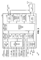
- FIG. 3 is a block diagram illustrating in more detail the wireless terminal of FIG. 2, with particular emphasis on the digital processing components of the wireless terminal;
- FIG. 4 is a block diagram illustrating the general structure of a GSM frame and the manner in which data blocks are carried by the GSM frame;
- FIG. 5 is a block diagram illustrating the formation of down link transmissions
- FIG. 6 is a block diagram illustrating the stages associated with recovering a data block from a series of RF bursts
- FIGs. 7A and 7B are flow charts illustrating operation of a wireless terminal in receiving and processing a RF burst.
- FIG. 8 is a flow chart illustrating operations to extract USF bits according to an embodiment of the present invention.
- FIG. 1 is a system diagram illustrating a portion of a cellular wireless communication system 100 that supports wireless terminals operating according to the present invention.
- the cellular wireless communication system 100 includes a Mobile Switching Center (MSC) 101, Serving GPRS Support Node/Serving EDGE Support Node (SGSN/SESN) 102, base station controllers (BSCs) 152 and 154, and base stations 103, 104, 105, and 106.
- the SGSN/SESN 102 couples to the Internet 114 via a GPRS Gateway Support Node (GGSN) 112.
- a conventional voice terminal 121 couples to the PSTN 110.
- a Voice over Internet Protocol (VoIP) terminal 123 and a personal computer 125 couple to the Internet 114.
- the MSC 101 couples to the Public Switched Telephone Network (PSTN) 110.
- PSTN Public Switched Telephone Network
- Each of the base stations 103-106 services a cell/set of sectors within which it supports wireless communications.
- Wireless links that include both forward link components and reverse link components support wireless communications between the base stations and their serviced wireless terminals. These wireless links support digital data communications, VoIP communications, and other digital multimedia communications.
- the cellular wireless communication system 100 may also be backward compatible in supporting analog operations as well.
- the cellular wireless communication system 100 supports the Global System for Mobile telecommunications (GSM) standard and also the Enhanced Data rates for GSM (or Global) Evolution (EDGE) extension thereof.
- the cellular wireless communication system 100 may also support the GSM General Packet Radio Service (GPRS) extension to GSM.
- GSM Global System for Mobile telecommunications
- EDGE Enhanced Data rates for GSM
- GPRS General Packet Radio Service
- the present invention is also applicable to other standards as well, e.g., TDMA standards, CDMA standards, etc.
- the teachings of the present invention apply to how the wireless terminal determines its uplink
- Wireless terminals 116, 118, 120, 122, 124, 126, 128, and 130 couple to the cellular wireless communication system 100 via wireless links with the base stations 103-106.
- wireless terminals may include cellular telephones 116 and 118, laptop computers 120 and 122, desktop computers 124 and 126, and data terminals 128 and 130.
- the cellular wireless communication system 100 supports communications with other types of wireless terminals as well.
- devices such as laptop computers 120 and 122, desktop computers 124 and 126, data terminals 128 and 130, and cellular telephones 116 and 118, are enabled to "surf" the Internet 114, transmit and receive data communications such as email, transmit and receive files, and to perform other data operations.
- Some or all of the wireless terminals 116-130 are therefore enabled to support the GPRS and/or EDGE operating standard as well as supporting the voice servicing portions the GSM standard.
- the wireless terminals 116-130 support the pipelined processing of received RF bursts in slots of a GSM frame so that a plurality of slots in each sub-frame of a GSM frame are allocated for forward link transmissions to a single wireless terminal.
- a number of slots of a GSM frame are allocated for forward link transmissions to a wireless terminal such that the wireless terminal must receive and process a number of RF bursts, e.g., 2, 3, 4, or more RF bursts, in each sub-frame of the GSM frame.
- the wireless terminal is able to process the RF bursts contained in these slots and still service reverse link transmissions and the other processing requirements of the wireless terminal.
- FIG. 2 is a block diagram functionally illustrating a wireless terminal 200 constructed according to the present invention.
- the wireless terminal 200 of FIG. 2 includes an RF transceiver 202, digital processing components 204, and various other components contained within a housing.
- the digital processing components 204 includes two main functional components, a physical layer processing, speech COder/DECoder (CODEC), and baseband CODEC functional block 206 and a protocol processing, man-machine interface functional block 208.
- CODEC speech COder/DECoder
- a Digital Signal Processor is the major component of the physical layer processing, speech COder/DECoder (CODEC), and baseband CODEC functional block 206 while a microprocessor, e.g., Reduced Instruction Set Computing (RISC) processor, is the major component of the protocol processing, man-machine interface functional block 208.
- the DSP may also be referred to as a Radio Interface Processor (RIP) while the RISC processor may be referred to as a system processor.
- RIP Radio Interface Processor
- RISC processor may be referred to as a system processor.
- the RF transceiver 202 couples to an antenna 203, to the digital processing components 204, and also to a battery 224 that powers all components of the wireless terminal 200.
- the physical layer processing, speech COder/DECoder (CODEC), and baseband CODEC functional block 206 couples to the protocol processing, man-machine interface functional block 208 and to a coupled microphone 226 and speaker 228.
- the protocol processing, man-machine interface functional block 208 couples to a Personal Computing/Data Terminal Equipment interface 210, a keypad 212, a Subscriber Identification Module (SIM) port 213, a camera 214, a flash RAM 216, an SRAM 218, a LCD 220, and LED(s) 222.
- SIM Subscriber Identification Module
- the camera 214 and LCD 220 may support either/both still pictures and moving pictures.
- the wireless terminal 200 of FIG. 2 supports video services as well as audio services via the cellular network.
- FIG. 3 is a block diagram illustrating in more detail the wireless terminal of FIG. 2, with particular emphasis on the digital processing components of the wireless terminal.
- the digital processing components 204 include a system processor 302, a baseband processor 304, and a plurality of supporting components.
- the supporting components include an external memory interface 306, MMI drivers and I/F 308, a video I/F 310, an audio I/F 312, a voice band CODEC 314, auxiliary functions 316, a modulator/demodulator 322, ROM 324, RAM 326 and a plurality of processing modules.
- the modulator/demodulator 322 is not a separate structural component with these functions being performed internal to the baseband processor 304.
- the processing modules are also referred to herein as accelerators, co-processors, processing modules, or otherwise, and include auxiliary functions 316, an equalizer module 318, an enCOder/DECoder (CODEC) processing module 320, and an Incremental Redundancy (IR) processing module 328.
- auxiliary functions 316 an equalizer module 318
- CODEC enCOder/DECoder
- IR Incremental Redundancy
- FIG. 3 are one example of a manner in which these components may be interconnected. Other embodiments support additional/alternate couplings. Such coupling may be direct, indirect, and/or may be via one or more intermediary components.
- RAM and ROM service both the system processor 302 and the baseband processor 304.
- Both the system processor 302 and the baseband processor 304 may couple to shared RAM 326 and ROM 324, couple to separate RAM, coupled to separate ROM, couple to multiple RAM blocks, some shared, some not shared, or may be served in a differing manner by the memory.
- the system processor 302 and the baseband processor 304 coupled to respective separate RAMs and ROMs and also couple to a shared RAM that services control and data transfers between the devices.
- the processing modules 316, 318, 320, 322, and 328 may coupled as illustrated in FIG. 3 but may also coupled in other manners in differing embodiments.
- the system processor 302 services at least a portion of a serviced protocol stack, e.g., GSM/GPRS/EDGE protocol stack.
- a serviced protocol stack e.g., GSM/GPRS/EDGE protocol stack.
- the system processor 302 services Layer I (L1) operations 330, a portion of Incremental Redundancy (IR) GSM protocol stack operations 332 (referred to as "IR control process"), Medium Access Control (MAC) operations 334, and Radio Link Control (RLC) operations 336.
- L1 Layer I
- IR control process Incremental Redundancy
- MAC Medium Access Control
- RLC Radio Link Control
- the baseband processor 304 in combination with the modulator/demodulator 322, RF transceiver, equalizer module 318, and/or encoder/decoder module 320 service the Physical Layer (PHY) operations performed by the digital processing components 204.
- the baseband processor 304 may also services a portion of the GSM/GPRS/EDGE protocol stack.
- the baseband processor 304 controls the interaction of the baseband processor 304 and equalizer module 318. As will be described further with reference to FIGs. 5-7B, the baseband processor 304 is responsible for causing the equalizer module 318 and the CODEC processing module 320 to process received RF bursts that reside within slots of a GSM frame. In the particular embodiment of FIGs. 2 and 3, with single RF front end 202, wireless terminal 200 may receive and process RF bursts in up to four slots of each sub-frame of a GSM frame, i.e., be assigned four slots for forward link transmissions in any particular GSM frame.
- the wireless terminal 200 may be assigned more than four slots in each sub-frame of the GSM frame. In this case, required transmit operations would be performed using a second RF front end while a first RF front end would perform the receive operations.
- the wireless terminal could receive and transmit at the same time.
- FIG. 4 is a block diagram illustrating the general structure of a GSM frame and the manner in which data blocks are carried by the GSM frame.
- the GSM frame is 20 ms in duration, including guard periods, is divided into four sub-frames, and includes eight slots, slots 0 through 7, in each sub-frame.
- Each slot is approximately 577 ⁇ s in duration, includes a left side, a midamble, and a right side. The left side and right side of an RF burst of the time slot carry data while the midamble is a training sequence.
- the RF bursts of four time slots of the GSM frame carry a segmented RLC block, a complete RLC block, or two RLC blocks, depending upon a supported Modulation and Coding Scheme (MCS) mode or GPRS CS-n mode, e.g., CS-1, CS-2.
- MCS Modulation and Coding Scheme
- GPRS CS-n mode e.g., CS-1, CS-2.
- data block A is carried in slot 0 of sub-frame 1, slot 0 of sub-frame 2, slot 0 of sub-frame 3, and slot 0 of sub-frame 3.
- Data block A may carry a segmented RLC block, an RLC block, or two RLC blocks.
- data block B is carried in slot 1 of sub-frame 1, slot 1 of sub-frame 2, slot 1 of sub-frame 3, and slot 1 of sub-frame 3.
- the MCS mode or CS mode of each set of slots, i.e., slot n of each sub-frame, for the GSM frame is consistent for the GSM frame. Further, the MCS mode or CS mode of differing sets of slots of the GSM frame, e.g., slot 0 of each sub-frame vs. any of slots 1-7 of each sub-frame, may differ. As will be described further with reference to FIG. 5, the wireless terminal 200 may be assigned multiple slots for forward link transmissions that must be received and processed by the wireless terminal 200.
- FIG. 5 depicts the various stages associated with mapping data into RF bursts.
- a Data Block Header and Data are initially uncoded.
- the Data Block Header contains Uplink Status Flags (USF) bits and other header information.
- the block coding operations perform the outer coding for the data block and support error detection/correction for data block.
- the outer coding operations typically employ a cyclic redundancy check (CRC) or a Fire Code.
- CRC cyclic redundancy check
- the outer coding operations are illustrated to add tail bits and/or a Block Code Sequence (BCS), which is/are appended to the Data.
- CS-1 the header and data are coded together using block coding and convolutional coding.
- the USF bits may be placed at specific known positions, depending on the coding scheme. Additionally, in these non-CS-1 coding schemes, the header and data is often coded separately
- the Fire Codes allow for either error correction or error detection.
- the Fire Code is a shortened binary cyclic code that appends 40 redundancy bits to 184 bits of the data Header and Data.
- the pure error detection capability of Fire Coding is sufficient to let undetected errors go through with only a probability of 2 -40 .
- After block coding has supplemented the Data with redundancy bits for error detection, calculation of additional redundancy for error correction to correct the transmissions caused by the radio channels.
- the internal error correction or coding scheme of GSM is based on convolutional codes.
- Some redundant bits generated by the convolutional encoder are punctured prior to transmission. Puncturing increases the rate of the convolutional code and reduces the redundancy per data block transmitted. Puncturing additionally lowers the bandwidth requirements such that the convolutional encoded signal fits into the available channel bit stream.
- the convolutional encoded punctured bits are passed to an interleaver, which shuffles various bit streams and segments the interleaved bit streams into the 4 bursts shown.
- FIG. 6 is a block diagram depicting the various stages associated with recovering a data block from an RF burst.
- Four RF bursts making up a data block are received and processed. Once all four RF bursts have been received, the RF bursts are combined to form an encoded data block.
- the encoded data block is then depunctured (if required), decoded according to an inner decoding scheme, and then decoded according to an outer decoding scheme.
- the decoded data block includes the data block header and the data.
- the wireless terminal may be concerned only with the USF bits contained within the header.
- the USF bits indicate whether a corresponding uplink is being used and, if it is, the identity of a wireless terminal currently allowed to use the uplink.
- partial decoding may be possible to identify data not intended for the receiving wireless terminal.
- USF bits consist of three bits located at the beginning of each radio block transmitted on the downlink. This embodiment enables coding eight different USF states, which are used to direct uplink traffic. More specifically, the USF bits tell multiple wireless terminals how to communicate with the servicing base station according to a predetermined schedule.
- FIGs. 7A and 7B are flow charts illustrating operation of a wireless terminal 200 in receiving and processing a RF burst.
- the operations illustrated in FIG. 7A to 7B correspond to a single RF burst in a corresponding slot of GSM frame.
- the RF front end 202, the baseband processor 304, and the equalizer module 318 illustrated in FIG. 3 perform these operations. These operations are generally called out as being performed by one of these components. However, the split of processing duties among these various components may differ without departing from the scope of the present invention.
- operation commences with the RF front end 202 receiving an RF burst in a corresponding slot of a GSM frame (step 602).
- the RF front end 202 then converts the RF burst to a baseband signal (step 604).
- the RF front end 202 sends an interrupt to the baseband processor 304 (step 606).
- the RF front end 202 performs steps 602-606.
- the baseband processor 304 receiving the baseband signal (step 608).
- either the RF front end 202, the baseband processor 304, or modulator/demodulator 322 will sample the analog baseband signal to digitize the baseband signal.
- the baseband processor 304 After receipt of the baseband signal (in a digitized format), the baseband processor 304 performs blind detection of a modulation format of the baseband signal (step 610). This blind detection of the modulation format determines the modulation format of the corresponding baseband signal.
- the modulation format will be either Gaussian Minimum Shift Keying (GMSK) modulation or Eight Phase Shift Keying (8PSK) modulation.
- GMSK Gaussian Minimum Shift Keying
- 8PSK Eight Phase Shift Keying
- the baseband processor 304 performs de-rotation and frequency correction of the baseband signal (step 614). Next, the baseband processor 304 performs burst power estimation of the baseband signal (step 616). Referring now to FIG. 7B via off page connector A, the baseband processor 304 next performs timing, channel, noise, and signal-to-noise ratio (SNR) estimation (step 620). Subsequently, the baseband processor 304 performs automatic gain control (AGC) loop calculations (step 622). Next, the baseband processor 304 performs soft decision scaling factor determination on the baseband signal (step 624). After step 624, the baseband processor 304 performs matched filtering operations on the baseband signal (step 626).
- SNR signal-to-noise ratio
- Steps 608-626 are referred to hereinafter as pre-equalization processing operations.
- the baseband processor 304 With the baseband processor 304 performing these pre-equalization processing operations on the baseband signal it produces a processed baseband signal. Upon completion of these pre-equalization processing operations, the baseband processor 304 issues a command to the equalizer module 318.
- the equalizer module 318 upon receiving the command, prepares to equalize the processed baseband signal based upon the modulation format, e.g., GMSK modulation or 8PSK modulation.
- the equalizer module 318 receives the processed baseband signal, settings, and/or parameters from the baseband processor 304 and performs Maximum Likelihood Sequence Estimation (MLSE) equalization on the left side of the baseband signal (step 628).
- MLSE Maximum Likelihood Sequence Estimation
- each RF burst contains a left side of data, a midamble, and a right side of data.
- the equalizer module 318 equalizes the left side of the RF burst to produce soft decisions for the left side.
- the equalizer module 318 equalizes the right side of the processed baseband signal (step 630). The equalization of the right side produces a plurality of soft decisions corresponding to the right side.
- the equalizer module 318 then issues an interrupt to the baseband processor 304 indicating that the equalizer operations are complete for the RF burst.
- the baseband processor 304 receives the soft decisions from the equalizer module 318.
- the baseband processor 304 determines an average phase of the left and right sides based upon the soft decisions received from the equalizer module 318 (step 632).
- the baseband processor 304 then performs frequency estimation and tracking based upon the soft decisions received from the equalizer module 318 (step 636).
- the operations of step 632 (or step 654) and step 636 are referred to herein as "post-equalization processing.” After operation at step 636, processing of the particular RF burst is completed.
- the baseband processor 304 and equalizer module 318 take the right branch from step 612 when an 8PSK modulation is blindly detected at step 610.
- the baseband processor 304 performs de-rotation and frequency correction on the baseband signal (step 618).
- the baseband processor 304 then performs burst power estimation of the baseband signal (step 620).
- FIG. 7B via off page connector B, operation continues with the baseband processor 304 performing timing, channel, noise, and SNR estimations (step 640).
- the baseband processor 304 then performs AGC loop calculations on the baseband signal (step 642).
- the baseband processor 304 calculates Decision Feedback Equalizer (DFE) coefficients that will be used by the equalizer module 318 (step 644).
- the baseband processor 304 then performs pre-equalizer operations on the baseband signal (step 646).
- the baseband processor 304 determines soft decision scaling factors for the baseband signal (step 648). Steps 618-648 performed by the baseband processor 304 are referred to herein as "pre-equalization processing" operations for an 8PSK modulation baseband signal.
- the baseband processor 304 issues a command to equalizer module 318 to equalize the processed baseband signal.
- the equalizer module 318 Upon receipt of the command from the baseband processor 304, the equalizer module 318 receives the processed baseband signal, settings, and/or parameters from the baseband processor 304 and commences equalization of the processed baseband signal. The equalizer module 318 first prepares state values that it will use in equalizing the 8PSK modulated processed baseband signal (step 650). In the illustrated embodiment the equalizer module 318 uses a Maximum A posteriori Probability (MAP) equalizer. The equalizer module 318 then equalizes the left and right sides of the processed baseband signal using the MAP equalizer to produce soft decisions for the processed baseband signal (step 652). Upon completion of step 654, the equalizer module 318 issues an interrupt to the baseband processor 304 indicating its completion of equalizing the processed baseband signal corresponding.
- MAP Maximum A posteriori Probability
- the baseband processor 304 then receives the soft decisions from the equalizer module 318. Next, the baseband processor 304 determines the average phase of the left and right sides of the processed baseband signal based upon the soft decisions (step 654). Finally, the baseband processor 304 performs frequency estimation and tracking for the soft decisions (step 636). The operations of steps 654 and 636 are referred to as post-equalization processing operations. From step 636, operation is complete for the particular RF burst depicts the various stages associated with recovering a data block from an RF Burst.
- FIGs. 7A and 7B are indicated to be performed by particular components of the wireless terminal, such segmentation of operations could be performed by differing components.
- the equalization operations could be performed by the baseband processor 304 or system processor 302 in other embodiments.
- decoding operations could also be performed by the baseband processor 304 or the system processor 302 in other embodiments.
- FIG. 8 is a flow chart illustrating operations to extract USF bits according to an embodiment of the present invention. Operations commence receiving and processing an RF burst in steps 702 and as described with reference to FIGs. 7A and 7B. When the block is complete, as determined at step 704, operation proceeds to step 706.
- the coding scheme may be any one of the CS-1 through CS-4 or MCS-1 through MCS-9 coding schemes.
- the USF bits are located at a known position and are also protected by precoding. This fact allows the USF bits to be easily extracted and decoded in these coding schemes.
- the header and data are coded together and this CS-1channel coding protects the USF bits.
- the CS-1 coding may be used to carry all control and configuration information, one can appreciate that timing is critical for GPRS and EDGE multi-slot operations.
- CS-1 coding requires special processing to quickly extract the USF bits if the wireless terminals are to meet timing requirements for the wireless terminal to transmit immediately to the servicing base station.
- the USF bits are protected by convolutional coding and error correction coding. Decoding must be performed, at least partially, to extract these USF bits. This differs from CS-2 through CS-4 and MCS-1 through MCS-9, where the USF bits are located in known positions and are protected by a strong precoding scheme. By locating this information in specific positions, the USF bits in non CS-1 coding schemes are easily extracted. However, for CS-1, the USF bits are extracted by partially decoding the CS-1 encoded data block (step 714). The remaining header and data bits may be left for further background processing when processor time is available. For CS-1 encoded data, this processing must occur to determine if the data is intended for the receiving wireless terminal.
- the header and data are coded separately. This allows the header to be decoded and evaluated. As the header contains information indicating if the data is intended for the receiving wireless terminal, the data need not be decoded when the data is not intended for the receiving wireless terminal. By not performing these decoding operations for these non-CS-1 coding schemes, power consumption and processing requirements of the wireless terminal are reduced. Additionally, resources associated with normal block processing of a data block not intended for the receiving wireless terminal are freed for other uses. This allows the wireless terminals to achieve an extended battery life by not performing an inner decode of a data block and an outer decode of a data block not intended for the receiving wireless terminal.
- step 706 Recovery of the USF bits begins in step 706 where, if necessary, the data block is decrypted.
- the data block is then de-interleaved (step 708).
- MCS-1 through MCS-4 and CS-1 through CS-4 interleave the header and data. This requires de-interleaving when receiving data blocks coded in these coding schemes.
- the data block is then de-punctured to produce a convoluted data block (step 710).
- step 712 a partial decode of the de-interleaved and de-punctured data block commences.
- a full decode of the data block may require 228 decoding steps.
- the USF bits are decoded and may be extracted in only 20 decoding steps, for example.
- the term “substantially” or “approximately”, as may be used herein, provides an industry-accepted tolerance to its corresponding term. Such an industry-accepted tolerance ranges from less than one percent to twenty percent and corresponds to, but is not limited to, component values, integrated circuit process variations, temperature variations, rise and fall times, and/or thermal noise.
- the term “operably coupled”, as may be used herein, includes direct coupling and indirect coupling via another component, element, circuit, or module where, for indirect coupling, the intervening component, element, circuit, or module does not modify the information of a signal but may adjust its current level, voltage level, and/or power level.
- inferred coupling includes direct and indirect coupling between two elements in the same manner as “operably coupled”.
- the term "compares favorably”, as may be used herein indicates that a comparison between two or more elements, items, signals, etc., provides a desired relationship. For example, when the desired relationship is that signal I has a greater magnitude than signal 2, a favorable comparison may be achieved when the magnitude of signal 1 is greater than that of signal 2 or when the magnitude of signal 2 is less than that of signal 1.
Landscapes
- Engineering & Computer Science (AREA)
- Computer Networks & Wireless Communication (AREA)
- Signal Processing (AREA)
- Quality & Reliability (AREA)
- Mobile Radio Communication Systems (AREA)
Applications Claiming Priority (4)
| Application Number | Priority Date | Filing Date | Title |
|---|---|---|---|
| US47892203P | 2003-06-16 | 2003-06-16 | |
| US478922P | 2003-06-16 | ||
| US749492 | 2003-12-31 | ||
| US10/749,492 US7342956B2 (en) | 2003-06-16 | 2003-12-31 | System and method to extract uplink status flag bits in a cellular wireless network |
Publications (2)
| Publication Number | Publication Date |
|---|---|
| EP1489873A2 true EP1489873A2 (de) | 2004-12-22 |
| EP1489873A3 EP1489873A3 (de) | 2011-11-02 |
Family
ID=33424126
Family Applications (2)
| Application Number | Title | Priority Date | Filing Date |
|---|---|---|---|
| EP04008246A Withdrawn EP1489873A3 (de) | 2003-06-16 | 2004-04-05 | System und Verfahren zum Extrahieren von Zustandsanzeigebits in einem zellularen, drahtlosen Netzwerk |
| EP04012583A Expired - Lifetime EP1489874B1 (de) | 2003-06-16 | 2004-05-27 | System und Verfahren zur Gewinnung von Statusflaggebits der Aufwärtsverbindung in einem zellularen, drahtlosen Netzwerk |
Family Applications After (1)
| Application Number | Title | Priority Date | Filing Date |
|---|---|---|---|
| EP04012583A Expired - Lifetime EP1489874B1 (de) | 2003-06-16 | 2004-05-27 | System und Verfahren zur Gewinnung von Statusflaggebits der Aufwärtsverbindung in einem zellularen, drahtlosen Netzwerk |
Country Status (3)
| Country | Link |
|---|---|
| US (2) | US7342956B2 (de) |
| EP (2) | EP1489873A3 (de) |
| DE (1) | DE602004007985T2 (de) |
Cited By (3)
| Publication number | Priority date | Publication date | Assignee | Title |
|---|---|---|---|---|
| GB2416961A (en) * | 2004-08-04 | 2006-02-08 | Matsushita Electric Ind Co Ltd | Uplink status flag (USF) detection for GPRS |
| CN101237296B (zh) * | 2007-01-30 | 2011-09-14 | 华为技术有限公司 | 基于压缩传输时间间隔的编码方法以及装置 |
| CN105406942A (zh) * | 2015-10-28 | 2016-03-16 | 无锡峰巢美家网络科技有限公司 | 一种通信数据去交织装置与去交织方法 |
Families Citing this family (15)
| Publication number | Priority date | Publication date | Assignee | Title |
|---|---|---|---|---|
| US7434147B2 (en) * | 2004-03-24 | 2008-10-07 | Research In Motion Limited | Power reception optimization method, and associated apparatus, for operating upon an encoded data block |
| US7593339B2 (en) * | 2004-07-12 | 2009-09-22 | Qualcomm Incorporated | Rate control for packet-based wireless communication |
| US7254381B1 (en) * | 2004-10-19 | 2007-08-07 | Skyworks Solutions, Inc. | Reducing DSP schedule bottlenecks in edge through premature USF decoding |
| JP4732935B2 (ja) * | 2006-03-20 | 2011-07-27 | 株式会社エヌ・ティ・ティ・ドコモ | 基地局、移動局及び方法 |
| KR100964577B1 (ko) * | 2006-06-02 | 2010-06-21 | 삼성전자주식회사 | 통신 시스템에서 전력 제어 방법 및 시스템 |
| BRPI0809043A2 (pt) * | 2007-03-21 | 2014-09-16 | Marvell Dspc Ltd | Codificação de usf |
| US8238836B2 (en) * | 2007-07-09 | 2012-08-07 | Qualcomm Incorporated | Methods for sending small packets in a peer-to-peer (P2P) network |
| JP5297469B2 (ja) * | 2008-02-12 | 2013-09-25 | テレフオンアクチーボラゲット エル エム エリクソン(パブル) | 無線通信ネットワークにおける方法および装置 |
| US8498607B2 (en) | 2008-06-12 | 2013-07-30 | Qualcomm Incorporated | Methods and systems for power savings using a message indication header |
| US8121046B2 (en) * | 2008-11-21 | 2012-02-21 | At&T Mobility Ii Llc | Efficient block error rate evaluation in a femto cell network |
| US8964615B2 (en) | 2012-09-06 | 2015-02-24 | Qualcomm Incorporated | Methods and devices for facilitating early header decoding in communications devices |
| US9680609B2 (en) * | 2015-01-27 | 2017-06-13 | Telefonaktiebolaget Lm Ericsson (Publ) | Transmitting device, receiving device, controlling node, and methods therein, for transmitting a block to the receiving device |
| WO2016144129A1 (ko) * | 2015-03-12 | 2016-09-15 | 엘지전자 주식회사 | 비면허 대역에서의 데이터 수신 방법 및 이를 이용한 기기 |
| US10462705B1 (en) * | 2015-05-13 | 2019-10-29 | Sprint Spectrum L.P. | Systems and methods for preventing premature processing during beam forming |
| US10454615B2 (en) * | 2017-05-05 | 2019-10-22 | Khalifa University of Science and Technology | SD decoder for digital communications |
Citations (3)
| Publication number | Priority date | Publication date | Assignee | Title |
|---|---|---|---|---|
| WO2000005844A1 (en) * | 1998-07-24 | 2000-02-03 | Nokia Networks Oy | Method and packet radio system for transmitting modulation and signalling information |
| EP1059754A1 (de) * | 1999-06-09 | 2000-12-13 | Lucent Technologies Inc. | Kodierung eines gemeinsamen Kopfes für Packetvermittlungsnetzwerke |
| WO2001020838A1 (en) * | 1999-09-15 | 2001-03-22 | Ericsson Inc | Methods and systems for decoding headers on a radio channel |
Family Cites Families (21)
| Publication number | Priority date | Publication date | Assignee | Title |
|---|---|---|---|---|
| US5471500A (en) | 1994-03-08 | 1995-11-28 | At&T Ipm Corp. | Soft symbol decoding |
| FR2718906B1 (fr) | 1994-04-13 | 1996-05-24 | Alcatel Mobile Comm France | Procédé d'adaptation de l'interface air, dans un système de radiocommunication avec des mobiles, station de base, station mobile et mode de transmission correspondants. |
| FI100017B (fi) * | 1995-08-29 | 1997-08-15 | Nokia Telecommunications Oy | Yhteyden laadun estimointimenetelmä ja vastaanotin |
| US5862186A (en) * | 1995-12-01 | 1999-01-19 | Kumar; Derek D. | RF simplex spread spectrum receiver and method |
| FI106175B (fi) * | 1997-08-18 | 2000-11-30 | Nokia Mobile Phones Ltd | Datansiirto matkaviestinverkossa |
| US6240304B1 (en) | 1998-02-11 | 2001-05-29 | Nokia Mobile Phones Ltd. | Mobile terminal having RF power consumption optimization of extended standby mode |
| US6539205B1 (en) | 1998-03-23 | 2003-03-25 | Skyworks Solutions, Inc. | Traffic channel quality estimation from a digital control channel |
| GB2341296B (en) | 1998-09-04 | 2003-05-28 | Siemens Ag | Data detector and method of detecting data from a sequence of received signal samples |
| EP1033852A1 (de) | 1999-02-05 | 2000-09-06 | Alcatel | Unterdrückung von Gleichspannungsversätzen für Null-ZF-Funkempfänger |
| US6504884B1 (en) | 1999-05-12 | 2003-01-07 | Analog Devices, Inc. | Method for correcting DC offsets in a receiver |
| FI111505B (fi) * | 1999-05-31 | 2003-07-31 | Nokia Corp | Menetelmä ohjaustiedon välittämiseksi tiedonsiirtojärjestelmässä, tiedonsiirtojärjestelmä, langaton päätelaite ja tukiasemajärjestelmä |
| GB2355900B (en) | 1999-10-29 | 2004-03-17 | Ericsson Telefon Ab L M | Radio receiver |
| US6400928B1 (en) * | 1999-11-19 | 2002-06-04 | Telefonaktiebolaget L M Ericsson (Publ) | Method and system for blind detection of modulation |
| US6282182B1 (en) * | 2000-01-07 | 2001-08-28 | Motorola, Inc. | Method and apparatus for simultaneous circuit switched voice and GPRS data interchange |
| US7068623B1 (en) * | 2000-01-10 | 2006-06-27 | Nortel Networks Limited | Communicating traffic over a wireless channel in a mobile communications system |
| EP1139614A1 (de) * | 2000-03-28 | 2001-10-04 | Lucent Technologies Inc. | Eine verbesserte Methode zur Dekodierung von Uplink Status Flags für RT-EGPRS-Benutzer |
| EP1176750A1 (de) | 2000-07-25 | 2002-01-30 | Telefonaktiebolaget L M Ericsson (Publ) | Bestimmung der Verbindungsqualität eines Übertragungskanals in einem OFDM-Übertragungssystem |
| US6597733B2 (en) | 2001-03-05 | 2003-07-22 | Ensemble Communications, Inc. | Equalizer performance enhancements for broadband wireless applications |
| US7106792B2 (en) | 2001-06-04 | 2006-09-12 | Qualcomm, Inc. | Method and apparatus for estimating the signal to interference-plus-noise ratio of a wireless channel |
| US7149245B2 (en) * | 2002-04-29 | 2006-12-12 | Lucent Technologies Inc. | Link adaption in enhanced general packet radio service networks |
| FR2840477B1 (fr) * | 2002-06-03 | 2005-02-04 | Nortel Networks Ltd | Procede d'adaptation de liens radio et unite de controle mettant en oeuvre le procede |
-
2003
- 2003-12-31 US US10/749,492 patent/US7342956B2/en active Active
-
2004
- 2004-04-05 EP EP04008246A patent/EP1489873A3/de not_active Withdrawn
- 2004-05-27 DE DE602004007985T patent/DE602004007985T2/de not_active Expired - Lifetime
- 2004-05-27 EP EP04012583A patent/EP1489874B1/de not_active Expired - Lifetime
-
2006
- 2006-07-27 US US11/494,396 patent/US7907907B2/en not_active Expired - Fee Related
Patent Citations (3)
| Publication number | Priority date | Publication date | Assignee | Title |
|---|---|---|---|---|
| WO2000005844A1 (en) * | 1998-07-24 | 2000-02-03 | Nokia Networks Oy | Method and packet radio system for transmitting modulation and signalling information |
| EP1059754A1 (de) * | 1999-06-09 | 2000-12-13 | Lucent Technologies Inc. | Kodierung eines gemeinsamen Kopfes für Packetvermittlungsnetzwerke |
| WO2001020838A1 (en) * | 1999-09-15 | 2001-03-22 | Ericsson Inc | Methods and systems for decoding headers on a radio channel |
Cited By (5)
| Publication number | Priority date | Publication date | Assignee | Title |
|---|---|---|---|---|
| GB2416961A (en) * | 2004-08-04 | 2006-02-08 | Matsushita Electric Ind Co Ltd | Uplink status flag (USF) detection for GPRS |
| GB2416961B (en) * | 2004-08-04 | 2007-03-14 | Matsushita Electric Ind Co Ltd | Improved uplink status flag detection method for GPRS |
| CN101237296B (zh) * | 2007-01-30 | 2011-09-14 | 华为技术有限公司 | 基于压缩传输时间间隔的编码方法以及装置 |
| CN101542996B (zh) * | 2007-01-30 | 2012-06-27 | 华为技术有限公司 | 基于压缩传输时间间隔的编码方法以及装置 |
| CN105406942A (zh) * | 2015-10-28 | 2016-03-16 | 无锡峰巢美家网络科技有限公司 | 一种通信数据去交织装置与去交织方法 |
Also Published As
| Publication number | Publication date |
|---|---|
| EP1489874A2 (de) | 2004-12-22 |
| US7342956B2 (en) | 2008-03-11 |
| US7907907B2 (en) | 2011-03-15 |
| DE602004007985D1 (de) | 2007-09-20 |
| EP1489874B1 (de) | 2007-08-08 |
| EP1489874A3 (de) | 2005-12-21 |
| EP1489873A3 (de) | 2011-11-02 |
| US20040253958A1 (en) | 2004-12-16 |
| US20060264180A1 (en) | 2006-11-23 |
| DE602004007985T2 (de) | 2008-04-24 |
Similar Documents
| Publication | Publication Date | Title |
|---|---|---|
| US7027539B2 (en) | Pipeline architecture for multi-slot wireless link processing | |
| US7342956B2 (en) | System and method to extract uplink status flag bits in a cellular wireless network | |
| EP1489774B1 (de) | System und Verfahren zur Bestimmung einer Bitfehlerwahrscheinlichkeit von empfangenen Daten in einem zellularen, drahtlosen Netzwerk | |
| US7203461B2 (en) | Adaptive channel quality estimation algorithm to support link adaptation | |
| US7756483B2 (en) | Adaptive channel quality estimation algorithm to support link adaptation | |
| US7512199B2 (en) | Channel estimation method operable to cancel a dominant disturber signal from a received signal | |
| EP1699194A1 (de) | Mehrzweigentzerrereinheit zur Unterdrückung von Störsignalen in einem drahtlosen Empfänger | |
| EP1524773B1 (de) | System und Verfahren zur adaptiven Kanalfilterung einer Signalfolge in einem zellularen, drahtlosen Netzwerk | |
| US20070184806A1 (en) | System and method to perform adaptive channel filtering on a radio frequency burst in a cellular | |
| US7643549B2 (en) | Wireless device having a hardware accelerator to support equalization processing | |
| US7406139B2 (en) | System and method to identify a modulation format of a data frame within a cellular wireless network | |
| US7489741B2 (en) | System and method to perform DC compensation on a radio frequency burst in a cellular wireless network | |
| US7342979B2 (en) | Incremental redundancy support in a cellular wireless terminal having IR processing module | |
| US20100246640A9 (en) | Feedback of decoded data characteristics | |
| US7457379B2 (en) | Adaptive multi-step combined DC offset compensation for EDGE 8-PSK | |
| US7450635B2 (en) | Single antenna interference cancellation within a wireless terminal |
Legal Events
| Date | Code | Title | Description |
|---|---|---|---|
| PUAI | Public reference made under article 153(3) epc to a published international application that has entered the european phase |
Free format text: ORIGINAL CODE: 0009012 |
|
| AK | Designated contracting states |
Kind code of ref document: A2 Designated state(s): AT BE BG CH CY CZ DE DK EE ES FI FR GB GR HU IE IT LI LU MC NL PL PT RO SE SI SK TR |
|
| AX | Request for extension of the european patent |
Extension state: AL HR LT LV MK |
|
| RAP1 | Party data changed (applicant data changed or rights of an application transferred) |
Owner name: BROADCOM CORPORATION |
|
| PUAL | Search report despatched |
Free format text: ORIGINAL CODE: 0009013 |
|
| AK | Designated contracting states |
Kind code of ref document: A3 Designated state(s): AT BE BG CH CY CZ DE DK EE ES FI FR GB GR HU IE IT LI LU MC NL PL PT RO SE SI SK TR |
|
| AX | Request for extension of the european patent |
Extension state: AL HR LT LV MK |
|
| 17P | Request for examination filed |
Effective date: 20120502 |
|
| AKX | Designation fees paid |
Designated state(s): DE FR GB |
|
| 17Q | First examination report despatched |
Effective date: 20140919 |
|
| STAA | Information on the status of an ep patent application or granted ep patent |
Free format text: STATUS: THE APPLICATION IS DEEMED TO BE WITHDRAWN |
|
| 18D | Application deemed to be withdrawn |
Effective date: 20141104 |
|
| REG | Reference to a national code |
Ref country code: DE Ref legal event code: R079 Free format text: PREVIOUS MAIN CLASS: H04Q0007380000 Ipc: H04W0004000000 |
|
| REG | Reference to a national code |
Ref country code: DE Ref legal event code: R079 Free format text: PREVIOUS MAIN CLASS: H04Q0007380000 Ipc: H04W0004000000 Effective date: 20150421 |