EP1489868A1 - Radio communication system - Google Patents
Radio communication system Download PDFInfo
- Publication number
- EP1489868A1 EP1489868A1 EP03705284A EP03705284A EP1489868A1 EP 1489868 A1 EP1489868 A1 EP 1489868A1 EP 03705284 A EP03705284 A EP 03705284A EP 03705284 A EP03705284 A EP 03705284A EP 1489868 A1 EP1489868 A1 EP 1489868A1
- Authority
- EP
- European Patent Office
- Prior art keywords
- radio station
- subcarrier
- radio
- power
- station
- Prior art date
- Legal status (The legal status is an assumption and is not a legal conclusion. Google has not performed a legal analysis and makes no representation as to the accuracy of the status listed.)
- Withdrawn
Links
Images


Classifications
-
- H—ELECTRICITY
- H04—ELECTRIC COMMUNICATION TECHNIQUE
- H04L—TRANSMISSION OF DIGITAL INFORMATION, e.g. TELEGRAPHIC COMMUNICATION
- H04L5/00—Arrangements affording multiple use of the transmission path
- H04L5/003—Arrangements for allocating sub-channels of the transmission path
- H04L5/0044—Allocation of payload; Allocation of data channels, e.g. PDSCH or PUSCH
- H04L5/0046—Determination of the number of bits transmitted on different sub-channels
-
- H—ELECTRICITY
- H04—ELECTRIC COMMUNICATION TECHNIQUE
- H04B—TRANSMISSION
- H04B7/00—Radio transmission systems, i.e. using radiation field
- H04B7/24—Radio transmission systems, i.e. using radiation field for communication between two or more posts
- H04B7/26—Radio transmission systems, i.e. using radiation field for communication between two or more posts at least one of which is mobile
- H04B7/2643—Radio transmission systems, i.e. using radiation field for communication between two or more posts at least one of which is mobile using time-division multiple access [TDMA]
-
- H—ELECTRICITY
- H04—ELECTRIC COMMUNICATION TECHNIQUE
- H04L—TRANSMISSION OF DIGITAL INFORMATION, e.g. TELEGRAPHIC COMMUNICATION
- H04L5/00—Arrangements affording multiple use of the transmission path
- H04L5/0001—Arrangements for dividing the transmission path
- H04L5/0003—Two-dimensional division
- H04L5/0005—Time-frequency
- H04L5/0007—Time-frequency the frequencies being orthogonal, e.g. OFDM(A) or DMT
-
- H—ELECTRICITY
- H04—ELECTRIC COMMUNICATION TECHNIQUE
- H04L—TRANSMISSION OF DIGITAL INFORMATION, e.g. TELEGRAPHIC COMMUNICATION
- H04L5/00—Arrangements affording multiple use of the transmission path
- H04L5/003—Arrangements for allocating sub-channels of the transmission path
- H04L5/0058—Allocation criteria
- H04L5/006—Quality of the received signal, e.g. BER, SNR, water filling
-
- H—ELECTRICITY
- H04—ELECTRIC COMMUNICATION TECHNIQUE
- H04W—WIRELESS COMMUNICATION NETWORKS
- H04W36/00—Hand-off or reselection arrangements
- H04W36/16—Performing reselection for specific purposes
- H04W36/18—Performing reselection for specific purposes for allowing seamless reselection, e.g. soft reselection
Definitions
- the present invention relates to digital radio communication systems and more particularly to a method of enabling a fast and stable communication to be carried out in a cellular system with planar or horizontal service areas in which cells are constructed using the same frequency.
- radio services In radio systems, such as one for cellular phones, for example, radio services must cover communication areas in a planar fashion. Further, the range of radio transmission is limited and all of the service areas cannot be covered by a single base station ("access point”; to be hereafter referred to as "access point AP"). Accordingly, a plurality of access points AP are provided so that communications can continue despite the movement of terminal stations.
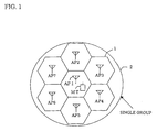
- each hexagon represents a cell 32 at the center of which an access point AP 31 is located.
- a terminal MT 33 is controlled by the access point AP 31 and communications are carried out between the access point AP 3 and the terminal MT 33.
- TDMA Time Division Multiple Access
- Fig. 10(a) shows the relationship between time and frequency in the FDMA (Frequency Division Multiple Access) method.
- Fig. 10(b) shows the relationship between time and frequency in the TDMA method.
- each user is allocated a different frequency, so that the same frequency is occupied by a particular user on the time axis during communication. Further, since there are a plurality of users in each single cell, a plurality of frequency channels are allocated to each cell. For example, there are users in cell 1 that conduct communications using frequencies f1 to f4. In cell 2, there are users who communicate using frequencies f5 to f8.
- the TDMA method employs one frequency (band) that is divided into small slots on the time axis, and the users conduct communications using their assigned slots.
- a slot must be allocated to each user repeatedly.
- a control is performed whereby, for example, a user is allocated in each period where a repetition period is taken as one cycle.
- the two access points AP1 and AP2 operate as communication systems of the TDMA method and that they have the same number of time slots (repetition periods) and the same time slot times that are synchronized between the first and second access points AP1 and AP2.
- the system shown in Fig .11 have eight time slots TS1 to TS8, for example.
- the first access point AP1 and a terminal communicate with each other using a second time slot TS2.
- the time slots TS1 and TS3 to TS8 are vacant.
- the use of the second time slot TS2 for communications between the second access point AP2 and the terminal would result in a large radio interference due to the communications going on between the first access point AP1 and the terminal. Therefore, the communications between the second access point AP2 and the terminal are carried out using a time slot selected from the remaining seven time slots other than the second time slot TS2.
- the frequency can be shared by different access points AP for communications among one another.
- the TDMA method is also advantageous for communications in which the transmission volume varies constantly, such as packet data communications.
- the vacancy state of time slots as minimum units has a large influence on the number of terminals that can be accommodated.
- the number of terminals that can be accommodated in each cell is determined by the number of time slots, the interference distance, and the cell arrangement.
- the received power (C) versus noise power (N) ratio (C/N), or the received power (C) versus interference power (I) ratio (C/I) that are required for communications are determined by the performance of the system or the terminals. If these conditions are not met, problems arise in communications.
- the expression (C/(N+I)), in which both of the above-mentioned influences are taken into consideration, might also be used as the indication of whether or not communications are possible.
- a time slot that can be used in a predetermined time slot TS is that slot on which the influence of interference due to other radio stations is not more than the above expression C/(N+I).
- a time slot in which an interference power exceeding an allowable power exists cannot be additionally allocated to an access point AP.
- a terminal that tries to connect to an access point AP has to measure the received power or the C/(N+I) ratio of every time slot and then notify the access point AP of the obtained information so that the access point AP can then allocate to the terminal a time slot that has no influence of interference and that is a vacant slot in the relevant cell.
- a hard handoff whereby the connection of a line between the terminal and an access point AP toward which the terminal is approaching is established after the connection of a line with the access point AP from which the terminal is moving is cut.
- the other is called a soft handoff whereby the connection of a line between the terminal MT and an approaching access point AP is established before disconnecting the connection of a line with the original access point AP, such that the weight of connection is gradually shifted from that with the original access point AP to the approaching access point AP.
- the same time slot is allocated for soft handoff.
- the terminal MT is thus allowed to carry out communications with the two access points AP at the same frequency and in the same time slot by emitting only one type of radio wave, thus realizing the soft handoff on the part of the system.
- Fig. 12 shows the manner in which the time slots are utilized in the above-described case. It is assumed that the two access points AP1 and AP2 are operated as TDMA radio communication systems and that they have the same number of time slots (repetition periods) and the same time slot times that are synchronized. The system shown in Fig. 12 involves eight time slots, for example.
- a first access point AP1 is communicating with a first terminal that exists in a cell of its own station, using a second time slot TS2.
- a second access point AP2 is communicating with a second terminal in a cell of its own station which is different from the first terminal, using a sixth time slot TS6.
- the TDMA system has the advantage of soft handoff, as the density of terminals increases, it becomes increasingly difficult to select a vacant time slot that is common to the two access points AP1 and AP2 and that has a reduced interference.
- the first radio station (a base station, for example) can arbitrarily allocate a time-divided time slot used for communication with the second radio station (a terminal station, for example) to a second radio station under the control of the first radio station.
- the base station can arbitrarily allocate time slots to terminal stations under the control of the base station without considering the interference with other cells.
- the interference power detection means may comprise the base station grouped with other base stations that can give interference in its own cell area, where the base stations transmit a notification signal one by one successively and periodically in a cyclic manner.
- the terminal station then calculates and stores the interference power state for each subcarrier of each base station, so that a ratio of the desired wave power to the interference power can be calculated for each subcarrier.
- the interference power detection means may comprise the base station grouped with other base stations that can give interference in its own cell area, wherein each base station comprises a means of transmitting a notification signal at the same time.
- the base stations terminate the transmission one by one successively and periodically in a cyclic manner, so that the terminal station can measure the interference power of the other base stations other than the base station with which the terminal is communicating and then calculate a ratio of the desired wave power to the interference power.
- the terminal station may categorize the received power from the base stations A and B and the interfering power from other stations into the following conditions on a subcarrier basis, so that more accurate handoff condition standards can be created.
- the handoff control is mainly carried out by base station A.
- the handoff control is mainly carried out by base station B. In this way, a more accurate handoff procedure can be performed.
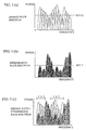
- the spectrum of the desired wave modulated by the OFDM method can be expressed as a composed wave of a number of subcarriers.
- Each of the subcarriers has temporal variations in accordance with the Rayleigh distribution due to the influence of fading. Namely, the electric power values vary temporally.
- the inventors thought of the spectrum of the desired wave and the interference wave (the relationship between power and frequency) at a given time as shown in Fig. 5(c). As shown, when looked at in subcarrier units and at a given time, it can be thought that there are frequency bands (fb1 and fb2 in the example of Fig. 5(c)) in which the power of the desired wave greatly exceeds the power intensity of the interference wave (i.e., the interference wave can be disregarded). In other words, in the frequency bands fb1 and fb2, the influence of the interference wave can be disregarded even when the same time slot is used, so that there is the possibility that different transmission and reception processes can be performed in the same time slot in communications between radio stations.
- the inventors further came up with the idea of providing a means for detecting the frequency bands fb1 and fb2 shown in Fig. 5(c) so that, by performing the transmission and reception processes using only these frequency bands (subcarriers), different transmission and reception processes can be reliably performed in the same time slot.
- the access point periodically transmits, for example, a detection signal that is used by the terminals in measuring the intensity of a signal from the access point and comparing it with the intensity of an interference signal.
- the detection signal must be transmitted by all of the access points.
- the access point AP1 emits the detection signal at a frequency that depends on the number of access points AP in a group that includes the cells of the access point AP1 and in which interference is thought to affect those cells.
- the radio communication system of the embodiment includes a single cell group 2 containing seven hexagonal cells 1.
- the cell group 2 has a cell configuration such that the cell in which a first access point AP1 exists has each of its six sides in contact with a side of each of the other six, surrounding cells. In the other six cells, there are located second to seventh access points AP2 to AP7, one access point for each cell.
- the cell in which the access point AP1 exists is influenced by an interference signal from the six other access points, so that these seven stations comprise a single group. In this case, the seven stations successively transmit a detection signal.
- a detection signal is transmitted from the access point AP1 once every seven times.
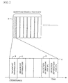
- Fig. 2 shows an example of the structure of a detection packet.
- a detection signal segment is provided in at least one time slot for use by grouped base stations.
- detection information is located in a time slot 3 for broadcast.
- the time slot in the radio communication system based on the TDMA method is made of a plurality of OFDM symbols in which broadcast data is allocated in the first half and detection signals 5 and 6 (including information indicating a signal is to be acquired from either access point AP1 or AP2) allocated for each access point AP are allocated in the latter half.
- detection signals 5 and 6 including information indicating a signal is to be acquired from either access point AP1 or AP2 allocated for each access point AP are allocated in the latter half.
- at least one OFDM signal must be occupied by a single access point AP.
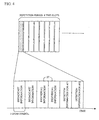
- the access points AP transmit successively two access points at a time in each repetition, the access points make a round after every 3.5 transmissions.
- the access points may be adapted to transmit one access point at a time, such that the repetition period consists of seven transmissions. This is dependent on the time that can be used for detection information which is determined by the number of the grouped access points AP, the length of one time slot, and the length of broadcast data, for example.
- each access point AP can transmit its own detection packet periodically.
- a terminal Upon reception of the transmitted signal, a terminal measures the intensity of the notification signal on a subcarrier basis.
- An example of a configuration is shown in Fig. 3.
- Fig. 3(a) shows a functional block diagram of an example of the radio terminal (MT) according to the present embodiment.
- Fig. 3(b) shows a functional block diagram of an example of the access point AP according to the present embodiment.
- a reception operation is carried out as the received signal is passed through an antenna, a frequency converter, a filter 7, an FFT 8, and a demodulator 9.
- a broadcast detection unit 13 the broadcast time slot is detected and detection information is extracted therefrom. Then, the power of each subcarrier is measured in a subcarrier power detection circuit 14. These items of information are then stored in a memory means 15 provided in a MAC layer (upper layer) 17 for each of the seven access points AP.
- the terminal station MT determines in a C/(N+I) calculation unit 16 the interference ratio to the access point AP1 on a subcarrier basis, namely C/(N+I).
- N+I is the undesired wave (interference wave) power, which is the sum of thermal noise and the interference from access point AP2 to access point AP7.
- the value (detection information) obtained by the C/(N+I) calculation unit 16 is then transmitted via a modulator 12, an IFFT (inverse Fourier transform) circuit 11, and a filter 10.
- the calculation of C/(N+I) is performed on the terminal (MT) end.
- the calculation may be performed on the access point AP1 end that has received individual measurement result via a transmission means.
- the base station selects a subcarrier that can be used for communications and then conduct communications.
- the signal transmitted from the terminal MT is sent via a filter 18, an FFT19 and a demodulator 20 to a determination circuit 25 in a MAC layer 26, where, based on the detection information, it is determined which subcarrier can be used for communications and only a subcarrier that can be used for communications is selected. This determination is made on the basis of the value of C/(N+I) determined by the performance of the terminal device and the system to which a system margin has been added.
- a transmission subcarrier selection circuit 24 selects a subcarrier that is transmitted.
- the determination circuit 25 notifies the upper layer of the number of information bits that can be transmitted in a single time slot. This is due to the fact that the overall required transmission time varies depending on the number of bits that can be transmitted, thus requiring a control in the upper layer.
- a broadcast packet including individual information 27 and detection information for access point AP1 and AP2 (information notifying that access point AP1 does not issue transmission information) is transferred to the terminal MT. Based on this signal, the terminal MT determines a subcarrier to be demodulated.
- the subcarrier that is transmitted is selected on the access point AP end
- a control signal from the terminal MT may be used.
- each subcarrier involves a power variation in accordance with the Rayleigh distribution, as mentioned above, such that there are subcarriers that exceed the predetermined C/(N+I).
- the radio communication technology according to the present embodiment in which the OFDM demodulation method is applied in the TDMA method
- individual subcarriers are independent, and even if the mean power is below the predetermined C/(N+I), each subcarrier involves a power variation in accordance with the Rayleigh distribution, as mentioned above, such that there are subcarriers that exceed the predetermined C/(N+I).
- time slots can be allocated based on the determination only by the access point AP of its own station.
- controls in the radio communication system are facilitated.
- the access point AP does not require the C/(N+I) information about all of the time slots from the terminal MT.
- the terminal MT there is no need for the terminal MT to measure the received power of all of the time slots or the C/(N+I) ratio.
- the terminal MT only needs to perform a reception operation in the time slot in its own station without monitoring the all of the time slots, so that the power consumption relating to monitoring purposes can be significantly reduced.
- the method of detecting interference power involved a calculation of C/(N+I) based on the reception of an individual access point AP signal.
- a signal composed of signals from stations other than its own station (for example, in a region 28, the sum of the power of the access points other than AP1 such that AP2+AP3+AP4+AP5+AP6+AP7) is transmitted periodically.
- (N+I) can be easily calculated by measuring the signals in the region 28.
- the sum of power except for AP2 i.e., AP1+AP3+AP4+AP5+AP6+AP7, is transmitted.
- controls are performed in the same manner as in the first embodiment, so that a subcarrier for communications can be also selected in the radio communication system according to the variation.
- the radio communication system of the second embodiment is characterized by a technique relating to the handoff process for the movement of a terminal across cells.
- the handoff process is a procedure allowing for a seamless transfer of access points such that the terminal as it moves can be connected to the radio communication system continuously.
- the intensity of radio waves from the two access points AP are compared in the terminal MT, and then a request is made for a handoff process.
- an optimum access point AP is selected between the access points AP based on the intensity of the radio wave from the terminal MT, delay time, and so on, and then instructions are made on the part of the radio communication system based on the selection.
- a handoff region is located in a boundary between the access points AP.
- the radio communication system includes two access points AP1 and AP2 disposed away from each other by a certain distance, and a mobile terminal MT.
- the soft handoff process when carrying out a soft handoff process that characterizes the TDMA method, if the power difference between the two access points AP1 and AP2 drops below a certain threshold value, the soft handoff process is initiated.
- the two access points AP1 and AP2 are connected with the terminal MT.
- the time slot that is used prior to the soft handoff region is controlled only within the access point AP1.
- a time slot must be vacant for both the access points AP1 and AP2. If the time slot is not vacant, any of the following measures can be taken:
- a common time slot for both access points AP can be secured in either way.
- the terminal MT can easily transition into the soft handoff process.
- the terminal MT After the control has transitioned into the soft handoff process, the terminal MT measures C/(N+I) as in the cases of the first embodiment of the radio communication system. In the present example, however, since the terminal MT is connected to the two access points (base stations), the terminal MT measures the C/(N+I) information about the two access points AP1 and AP2. Further, the signals from the two access points are classified into three conditions on a subcarrier basis.
- Fig. 8 shows a functional block diagram of an example of the terminal MT that has the aforementioned functions.
- the terminal shown in Fig. 8 detects the power of each subcarrier (a detection information detection unit 33, and a subcarrier power detection circuit 34) and stores it (a memory means 35), as does the terminal shown in Fig. 3. In addition, the terminal further classifies the subcarriers according to the following conditions 1 to 3 for the two access points AP1 and AP2.
- the control is maintained under the access point (base station A) AP1, while if the number of subcarriers with Conditions 2+3 is larger than the number of subcarriers with Condition 1, the control is transferred to the access point (base station B) AP2.
- the control may be placed under either access point.
- the in-between region should preferably be provided with a hysteresis, i.e., it should be placed under the control of the previous access point.
- the handoff is based on a total power alone.
- an importance should preferably be placed on the quality of actual communications and the control should be placed under the access point AP with a better C/(N+I) as a reference for demodulation performance.
- a control is performed such that communications are carried out using a subcarrier that can be used for communications, so that communications are possible even when there is interference from other stations.
- control is simplified and the need for the monitoring of all of the time slots by the terminal is eliminated, so that the power consumption by the terminal can be reduced.
- the soft handoff process can be performed easily.
- a control is perofrmed such that communications are carried out using a subcarrier that can be used for communications, so that communications are possible even when there is interference from other stations.
- the need for considering interference with other cells is eliminated, and time slots can be arbitrarily allocated to the terminal stations under the control of its own station.
Landscapes
- Engineering & Computer Science (AREA)
- Signal Processing (AREA)
- Computer Networks & Wireless Communication (AREA)
- Quality & Reliability (AREA)
- Mobile Radio Communication Systems (AREA)
- Time-Division Multiplex Systems (AREA)
Abstract
A TDMA radio communication system using a multiple subcarrier modulation
method and comprising at least a first and a second radio station. The first
radio station carries out communications by selectively modulating a
subcarrier with which a desired transmission rate can be obtained in the
second radio station, thereby providing a radio communication system that
does not require the monitoring of each time slot by a terminal.

Description
The present invention relates to digital radio communication systems
and more particularly to a method of enabling a fast and stable
communication to be carried out in a cellular system with planar or horizontal
service areas in which cells are constructed using the same frequency.
In radio systems, such as one for cellular phones, for example, radio
services must cover communication areas in a planar fashion. Further, the
range of radio transmission is limited and all of the service areas cannot be
covered by a single base station ("access point"; to be hereafter referred to as
"access point AP"). Accordingly, a plurality of access points AP are
provided so that communications can continue despite the movement of
terminal stations.
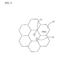
Specifically, a system called "cell configuration" is employed, as
shown in Fig. 9. Referring to Fig. 9, each hexagon represents a cell 32 at
the center of which an access point AP 31 is located. In each cell 32, a
terminal MT 33 is controlled by the access point AP 31 and communications
are carried out between the access point AP 3 and the terminal MT 33.
In this configuration, in order to allow services, such as telephone
services, to continue when the terminal MT moves, the individual cells 32
must be arranged at least in an adjoining manner or in such a manner that
they have partly overlapping areas therebetween. However, the adjoining
cells must communicate among themselves at different frequencies so as to
avoid their radio waves from entering each other and interfering with each
other. When communications are carried out at the same frequency, if the
communicating cells are apart from each other with a distance corresponding
to several cells, for example, the intensity of the interfering waves are
sufficiently reduced that no problems are caused. This type of system is
used in PDC (Personal Digital Cellular), for example, which is a current
cellular phone system.
However, since in this type of system the frequencies that can be
actually used in a single cell are only a fraction of the frequencies that are
allocated to the entire system, the volume of lines that can be accommodated
in a single cell is limited.
There has been a proposal to configure cells at the same frequency
using TDMA (Time Division Multiple Access) technology. With reference
to Fig. 10, the method of utilizing frequency and time in this technology will
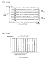
be described. Fig. 10(a) shows the relationship between time and frequency
in the FDMA (Frequency Division Multiple Access) method. Fig. 10(b)
shows the relationship between time and frequency in the TDMA method.
As shown in Fig. 10(a), in the FDMA method, each user is allocated a
different frequency, so that the same frequency is occupied by a particular
user on the time axis during communication. Further, since there are a
plurality of users in each single cell, a plurality of frequency channels are
allocated to each cell. For example, there are users in cell 1 that conduct
communications using frequencies f1 to f4. In cell 2, there are users who
communicate using frequencies f5 to f8.
As shown in Fig. 10(b), the TDMA method employs one frequency
(band) that is divided into small slots on the time axis, and the users conduct
communications using their assigned slots. When carrying out
communications, a slot must be allocated to each user repeatedly. For this
purpose, a control is performed whereby, for example, a user is allocated in
each period where a repetition period is taken as one cycle.
With reference to Fig. 11, the method of using time slots in a case
where a second access point AP2 exists in a cell adjacent to a first access
point AP1.
It is now assumed that the two access points AP1 and AP2 operate as
communication systems of the TDMA method and that they have the same
number of time slots (repetition periods) and the same time slot times that are
synchronized between the first and second access points AP1 and AP2. The
system shown in Fig .11 have eight time slots TS1 to TS8, for example.
As shown in Fig. 11, the first access point AP1 and a terminal (not
shown) communicate with each other using a second time slot TS2. In this
case, therefore, the time slots TS1 and TS3 to TS8 are vacant.
The use of the second time slot TS2 for communications between the
second access point AP2 and the terminal would result in a large radio
interference due to the communications going on between the first access
point AP1 and the terminal. Therefore, the communications between the
second access point AP2 and the terminal are carried out using a time slot
selected from the remaining seven time slots other than the second time slot
TS2.
By thus using the same frequency and dividing the time domain into a
plurality of time slots, the frequency can be shared by different access points
AP for communications among one another.
In the conventional frequency division method, it is difficult to freely
change the frequency width due to the limitations of analog circuits, such as
filters. On the other hand, there are no circuitry limitations in the TDMA
method since this method divides on the time axis. It is also possible for a
single terminal to use not just one time slot but two or three time slots. In
this way, the communication volume can be increased by two or three folds,
allowing bands to be freely controlled in multimedia communications, for
example.
Thus, the TDMA method is also advantageous for communications in
which the transmission volume varies constantly, such as packet data
communications.
In a communication system based on the TDMA method in which the
cell configuration is adopted as described above, the vacancy state of time
slots as minimum units has a large influence on the number of terminals that
can be accommodated. In the case where cells are assembled at the same
frequency, the number of terminals that can be accommodated in each cell is
determined by the number of time slots, the interference distance, and the cell
arrangement.
In radio communications, the received power (C) versus noise power
(N) ratio (C/N), or the received power (C) versus interference power (I) ratio
(C/I) that are required for communications are determined by the performance
of the system or the terminals. If these conditions are not met, problems
arise in communications. The expression (C/(N+I)), in which both of the
above-mentioned influences are taken into consideration, might also be used
as the indication of whether or not communications are possible.
Referring to Fig. 11, a time slot that can be used in a predetermined
time slot TS is that slot on which the influence of interference due to other
radio stations is not more than the above expression C/(N+I). For example,
a time slot in which an interference power exceeding an allowable power
exists cannot be additionally allocated to an access point AP.
Consequently, a terminal that tries to connect to an access point AP
has to measure the received power or the C/(N+I) ratio of every time slot and
then notify the access point AP of the obtained information so that the access
point AP can then allocate to the terminal a time slot that has no influence of
interference and that is a vacant slot in the relevant cell.
Further, when a packet communication is carried out in a TDMA
system, a particular terminal does not occupy a time slot constantly, but
rather vacant slots change all the time. Therefore, the terminal must
monitor the occupation state of every time slot continuously. This means
that the terminal is in a receiving state all the time, resulting in increasing
power consumption and other problems.
Moreover, as the number of terminals increases and the influence of
the radio waves used by adjacent cells increases, there could even be cases
where none of the time slots are available, putting a particular terminal in a
busy state. In such cases, communications with the particular terminal
cannot be conducted until its communication with another terminal ends, the
interfering station ends communications, or the radio environment changes as
the station attempting connection caused by movement of the station, for
example.
There is another problem relating to handoff. When a
communicating terminal moves across cells in a service area divided into
cells, the access points AP with which the terminal communicates are
switched in an operation ("handoff").
There are two types of handoff. One is called a hard handoff
whereby the connection of a line between the terminal and an access point AP
toward which the terminal is approaching is established after the connection
of a line with the access point AP from which the terminal is moving is cut.
The other is called a soft handoff whereby the connection of a line between
the terminal MT and an approaching access point AP is established before
disconnecting the connection of a line with the original access point AP, such
that the weight of connection is gradually shifted from that with the original
access point AP to the approaching access point AP.
Since the TDMA method employs the same frequency for
communications, the method characteristically realizes a soft handoff
procedure that allows the terminal MT to communicate with the original and
approaching access points AP simultaneously.
In the case of soft handoff, if the time slot that has been used by the
original access point AP is vacant in the approaching access point AP, the
same time slot is allocated for soft handoff. The terminal MT is thus
allowed to carry out communications with the two access points AP at the
same frequency and in the same time slot by emitting only one type of radio
wave, thus realizing the soft handoff on the part of the system.
Fig. 12 shows the manner in which the time slots are utilized in the
above-described case. It is assumed that the two access points AP1 and AP2
are operated as TDMA radio communication systems and that they have the
same number of time slots (repetition periods) and the same time slot times
that are synchronized. The system shown in Fig. 12 involves eight time
slots, for example.
A first access point AP1 is communicating with a first terminal that
exists in a cell of its own station, using a second time slot TS2. A second
access point AP2 is communicating with a second terminal in a cell of its own
station which is different from the first terminal, using a sixth time slot TS6.
It is now assumed that a soft handoff procedure is to be performed
and that a third terminal, which is about to initiate soft handoff, is
communicating using a fourth time slot. In this example, the soft handoff
procedure can be performed because the second access point AP 2 is not
using the fourth time slot TS4.
However, if a third access point AP (not shown) that is located
adjacent to or has a strong influence on the second access point AP2 is using
the fourth time slot TS4 such that, even though the second access point AP2
is not using the fourth time slot TS4, there is a strong interference, the
second access point AP2 may in some cases not be able to use the fourth time
slot TS4 for communications. In such cases, the soft handoff procedure
cannot be performed.
As explained above, while the TDMA system has the advantage of
soft handoff, as the density of terminals increases, it becomes increasingly
difficult to select a vacant time slot that is common to the two access points
AP1 and AP2 and that has a reduced interference.
It is therefore an object of the invention to provide a radio
communication system that does not require the monitoring of each time slot
by the terminals. It is another object of the invention to provide a
technology that can eliminate situations where a terminal cannot conduct
communications because none of the time slots are available or situations
where soft handoff cannot be performed.
In one aspect, the invention provides a TDMA radio communication
system that uses a multiple subcarrier modulation method and that comprises
at least a first and a second radio station, wherein said first radio station
carries out communications by selectively modulating a subcarrier with
which a desired transmission rate can be obtained in said second radio station.
The first radio station (a base station, for example) can arbitrarily
allocate a time-divided time slot used for communication with the second
radio station (a terminal station, for example) to a second radio station under
the control of the first radio station.
In the above TDMA radio communication system, the second radio
station preferably comprises: a power detection means for detecting the
received power for each subcarrier and detecting the interference power from
a radio station different from the first radio station with which said second
radio station is communicating; and a notification means for notifying said
first radio station of information regarding said received power and said
interference power detected by said detection means, and wherein said first
radio station comprises: a subcarrier selection means for selecting, based on a
reception state and an interference state of each subcarrier that have been
returned from said second radio station, a subcarrier with which a desired
transmission rate can be achieved in said second radio station; and a switch
means for turning on and off of modulation on a subcarrier basis.
In accordance with the invention, in a radio communication system
using a multiple carrier (multiple subcarrier) modulation method and based
on a cellular system in which a cell configuration is employed such that each
cell carries out connections in the TDMA method using the same frequency, a
terminal station detects the received power for each subcarrier and the
interference power for each subcarrier from other base stations other than the
base station with which the terminal is communicating, and then notifies the
base station. The base station, based on a reception state and an
interference state for each subcarrier that have been returned from the
terminal station, then selects a subcarrier with which a desired transmission
rate can be achieved in the terminal station, and then carries out
communication.
As a result, the base station can arbitrarily allocate time slots to
terminal stations under the control of the base station without considering the
interference with other cells.
The interference power detection means may comprise the base
station grouped with other base stations that can give interference in its own
cell area, where the base stations transmit a notification signal one by one
successively and periodically in a cyclic manner. The terminal station then
calculates and stores the interference power state for each subcarrier of each
base station, so that a ratio of the desired wave power to the interference
power can be calculated for each subcarrier.
In another embodiment, the interference power detection means may
comprise the base station grouped with other base stations that can give
interference in its own cell area, wherein each base station comprises a means
of transmitting a notification signal at the same time. The base stations
terminate the transmission one by one successively and periodically in a
cyclic manner, so that the terminal station can measure the interference
power of the other base stations other than the base station with which the
terminal is communicating and then calculate a ratio of the desired wave
power to the interference power.
In a soft handoff procedure, the terminal station may categorize the
received power from the base stations A and B and the interfering power from
other stations into the following conditions on a subcarrier basis, so that
more accurate handoff condition standards can be created.
If (the number of subcarriers with Conditions 1+3 > the number of
subcarriers with Condition 2), then the handoff control is mainly carried out
by base station A.
If (the number of subcarriers with Conditions 2+3 > the number of
subcarriers with Condition 1), then the handoff control is mainly carried out
by base station B. In this way, a more accurate handoff procedure can be
performed.
Before going into the details of the embodiments of the invention, the
inventors' analysis is described.
It had occurred to the inventors that by using the OFDM (Orthogonal
Frequency Division Multiplex) method for modulation in a radio
communication system based on the TDMA multiplication method, it might
be possible to allow radio communications to continue without interruption
even if the time slot used for radio communications between an access point
(a first radio station) and a terminal (a second radio station) is the same as
the time slot used for radio communications between radio stations that are
adjacent to the first and second radio stations.
This will be described in greater detail with reference to Figs. 5(a) to
5(c).
Fig. 5(a) shows a graph of the spectrum of a desired wave (a signal
that is actually used for radio communications), in which the ordinate shows
electric power and the abscissa shows frequency. When this spectrum as a
whole is considered a composed desired wave, the spectrum indicates a mean
power value that is defined by the dotted line MVD and independent of
frequency.
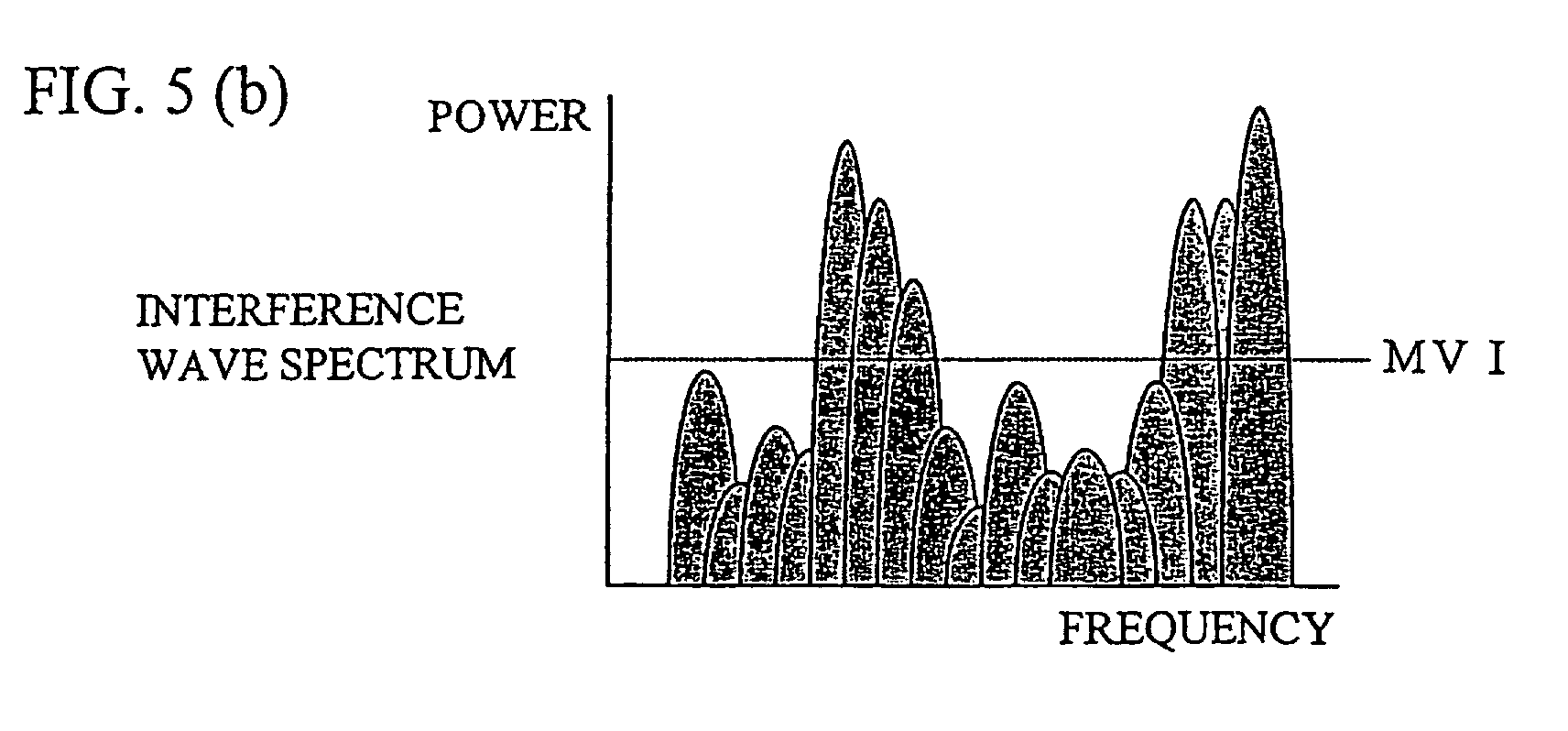
Fig. 5(b) shows a graph of the spectrum of an interference wave (a
signal that enters due to other radio communications). If this spectrum as a
whole is considered a composed interference wave, the spectrum indicates a
mean power value that is defined by the dotted line MVI and independent of
frequency.
If there is no difference in electric power values between the
composed desired wave of Fig. 5(a) and the composed interference wave of
Fig. 5(b) (such as when two radio communicating objects approach each
other), there would be no difference in electric power values at any frequency
between the composed desired wave and the composed interference wave, so
that it would be impossible to perform communications using the same time
slot.
In reality, however, as shown in Fig. 5(a), the spectrum of the desired
wave modulated by the OFDM method can be expressed as a composed wave
of a number of subcarriers. Each of the subcarriers has temporal variations
in accordance with the Rayleigh distribution due to the influence of fading.
Namely, the electric power values vary temporally.
The inventors thought of the spectrum of the desired wave and the
interference wave (the relationship between power and frequency) at a given
time as shown in Fig. 5(c). As shown, when looked at in subcarrier units
and at a given time, it can be thought that there are frequency bands (fb1 and
fb2 in the example of Fig. 5(c)) in which the power of the desired wave
greatly exceeds the power intensity of the interference wave (i.e., the
interference wave can be disregarded). In other words, in the frequency
bands fb1 and fb2, the influence of the interference wave can be disregarded
even when the same time slot is used, so that there is the possibility that
different transmission and reception processes can be performed in the same
time slot in communications between radio stations.
The inventors further came up with the idea of providing a means for
detecting the frequency bands fb1 and fb2 shown in Fig. 5(c) so that, by
performing the transmission and reception processes using only these
frequency bands (subcarriers), different transmission and reception processes
can be reliably performed in the same time slot.
Based on the above discussion, embodiments of the invention will be
described in the following.
A radio communication system according to a first embodiment of the
invention will be described by referring to the drawings.
A case will be described in which terminals exist in a cell in which an
access point is present. The terminals are connected as communication
systems to the network by conducting communications with the access point.
For this purpose, a time slot must be determined in which the
communications with the access point are conducted.
In accordance with the invention, a time slot among all of the time
slots provided for the access point by the system that is not allocated to any
other terminals in the station can be freely allocated for communications with
a particular terminal.
The access point periodically transmits, for example, a detection
signal that is used by the terminals in measuring the intensity of a signal from
the access point and comparing it with the intensity of an interference signal.
The detection signal must be transmitted by all of the access points.
Thus, the access point AP1 emits the detection signal at a frequency that
depends on the number of access points AP in a group that includes the cells
of the access point AP1 and in which interference is thought to affect those
cells.
Fig. 1 shows a conceptual chart of the radio communication system
according to the present embodiment.
As shown in Fig. 1, the radio communication system of the
embodiment includes a single cell group 2 containing seven hexagonal cells 1.
The cell group 2 has a cell configuration such that the cell in which a
first access point AP1 exists has each of its six sides in contact with a side of
each of the other six, surrounding cells. In the other six cells, there are
located second to seventh access points AP2 to AP7, one access point for
each cell.
In the radio communication system shown in Fig. 1, presumably the
cell in which the access point AP1 exists is influenced by an interference
signal from the six other access points, so that these seven stations comprise
a single group. In this case, the seven stations successively transmit a
detection signal.
Thus, a detection signal is transmitted from the access point AP1 once
every seven times.
Fig. 2 shows an example of the structure of a detection packet. As
shown, in a repetition period of time slots, a detection signal segment is
provided in at least one time slot for use by grouped base stations. In the
illustrated example, detection information is located in a time slot 3 for
broadcast. The time slot in the radio communication system based on the
TDMA method is made of a plurality of OFDM symbols in which broadcast
data is allocated in the first half and detection signals 5 and 6 (including
information indicating a signal is to be acquired from either access point AP1
or AP2) allocated for each access point AP are allocated in the latter half.
In order to measure a signal on a subcarrier basis, at least one OFDM signal
must be occupied by a single access point AP.
In the illustrated example, as the access points AP transmit
successively two access points at a time in each repetition, the access points
make a round after every 3.5 transmissions. Alternatively, the access points
may be adapted to transmit one access point at a time, such that the repetition
period consists of seven transmissions. This is dependent on the time that
can be used for detection information which is determined by the number of
the grouped access points AP, the length of one time slot, and the length of
broadcast data, for example. Thus, each access point AP can transmit its
own detection packet periodically.
Upon reception of the transmitted signal, a terminal measures the
intensity of the notification signal on a subcarrier basis. An example of a
configuration is shown in Fig. 3.
Fig. 3(a) shows a functional block diagram of an example of the radio
terminal (MT) according to the present embodiment. Fig. 3(b) shows a
functional block diagram of an example of the access point AP according to
the present embodiment.
As shown in Fig. 3(a), a reception operation is carried out as the
received signal is passed through an antenna, a frequency converter, a filter 7,
an FFT 8, and a demodulator 9. In a broadcast detection unit 13, the
broadcast time slot is detected and detection information is extracted
therefrom. Then, the power of each subcarrier is measured in a subcarrier
power detection circuit 14. These items of information are then stored in a
memory means 15 provided in a MAC layer (upper layer) 17 for each of the
seven access points AP.
Then, the terminal station MT determines in a C/(N+I) calculation
unit 16 the interference ratio to the access point AP1 on a subcarrier basis,
namely C/(N+I). (N+I) is the undesired wave (interference wave) power,
which is the sum of thermal noise and the interference from access point AP2
to access point AP7.
The value (detection information) obtained by the C/(N+I) calculation
unit 16 is then transmitted via a modulator 12, an IFFT (inverse Fourier
transform) circuit 11, and a filter 10.
In the present embodiment, the calculation of C/(N+I) is performed
on the terminal (MT) end. Alternatively, however, the calculation may be
performed on the access point AP1 end that has received individual
measurement result via a transmission means. Based on the result, the base
station selects a subcarrier that can be used for communications and then
conduct communications.
As shown in Fig.3(b), on the access point (AP) end, the signal
transmitted from the terminal MT is sent via a filter 18, an FFT19 and a
demodulator 20 to a determination circuit 25 in a MAC layer 26, where,
based on the detection information, it is determined which subcarrier can be
used for communications and only a subcarrier that can be used for
communications is selected. This determination is made on the basis of the
value of C/(N+I) determined by the performance of the terminal device and
the system to which a system margin has been added.
In response to the result of determination in the determination circuit
25, a transmission subcarrier selection circuit 24 selects a subcarrier that is
transmitted. In addition, the determination circuit 25 notifies the upper
layer of the number of information bits that can be transmitted in a single
time slot. This is due to the fact that the overall required transmission time
varies depending on the number of bits that can be transmitted, thus requiring
a control in the upper layer.
It is also necessary to place a signal in the control signal portion
instead of the information signal portion in order to notify the terminal MT of
which subcarrier carries a signal.
A configuration for this purpose is described below with reference to
Fig. 4.
As shown in Fig. 4, a broadcast packet including individual
information 27 and detection information for access point AP1 and AP2
(information notifying that access point AP1 does not issue transmission
information) is transferred to the terminal MT. Based on this signal, the
terminal MT determines a subcarrier to be demodulated.
While in the above-described example the subcarrier that is
transmitted is selected on the access point AP end, it is also possible to make
the selection on the terminal MT end and then notify the access point AP of a
usable subcarrier. In this case, there would be no need for the terminal to
determine which subcarrier carries a signal, thus simplifying the
configuration. For notification, a control signal from the terminal MT may
be used.
In the conventional TDMA system, if a time slot does not satisfy the
required C/(N+I), the communication quality cannot be maintained and the
time slot cannot be used.
In contrast, when the radio communication technology according to
the present embodiment (in which the OFDM demodulation method is applied
in the TDMA method) is applied, individual subcarriers are independent, and
even if the mean power is below the predetermined C/(N+I), each subcarrier
involves a power variation in accordance with the Rayleigh distribution, as
mentioned above, such that there are subcarriers that exceed the
predetermined C/(N+I). Thus, such subcarriers can then be detected and
used for communications, thereby making communications practically
possible.
This process is shown in Figs. 5(a) to (c), which show the spectra of a
desired wave and an interference wave.
As mentioned above, when looked at from the viewpoint of overall
power, there is not much difference in electric power between the desired
wave and the interference wave such that, when C/(N+I) of the overall power
is taken as an indicator, it looks as though communications cannot be
performed. However, as shown in Fig. 5(c), when recognized on a
subcarrier basis, it can be seen that there are a number of subcarriers in
which the desired C/(N+I) can be obtained. Thus, even in a case where time
slots have.been arbitrarily allocated by an access point AP, there exist regions
(fb1 and fb2) in which communications are possible using subcarriers. In
accordance with the radio communication technique of the present
embodiment, because the influence of interference on the access point AP
from other access points AP can be reduced, time slots can be allocated based
on the determination only by the access point AP of its own station. Thus,
controls in the radio communication system are facilitated.
The access point AP does not require the C/(N+I) information about
all of the time slots from the terminal MT. Thus, there is no need for the
terminal MT to measure the received power of all of the time slots or the
C/(N+I) ratio. As a result, the terminal MT only needs to perform a
reception operation in the time slot in its own station without monitoring the
all of the time slots, so that the power consumption relating to monitoring
purposes can be significantly reduced.
Hereafter, a variation of the radio communication system as described
above will be described by referring to the drawings. In this variation, a
different method of calculating interference power is used.
In the first embodiment of the invention, the method of detecting
interference power involved a calculation of C/(N+I) based on the reception
of an individual access point AP signal.
The present variation of the first embodiment employs a technique by
which a single station does not transmit in a cyclic manner, as described
below with reference to Fig. 6.
In the radio communication technique according to the first
embodiment, it was necessary to calculate individually for the individual
stations because signals were transmitted from the multiple stations
individually.
However, in the present variation, a signal composed of signals from
stations other than its own station (for example, in a region 28, the sum of the
power of the access points other than AP1 such that
AP2+AP3+AP4+AP5+AP6+AP7) is transmitted periodically. Thus, (N+I)
can be easily calculated by measuring the signals in the region 28. In a
region 29, the sum of power except for AP2, i.e.,
AP1+AP3+AP4+AP5+AP6+AP7, is transmitted. Thereafter, controls are
performed in the same manner as in the first embodiment, so that a subcarrier
for communications can be also selected in the radio communication system
according to the variation.
Hereafter, the radio communication system according to a second
embodiment of the invention will be described by referring to the drawings.
The radio communication system of the second embodiment is
characterized by a technique relating to the handoff process for the movement
of a terminal across cells.
The handoff process is a procedure allowing for a seamless transfer of
access points such that the terminal as it moves can be connected to the radio
communication system continuously.
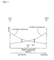
Referring to Fig. 7, in one example of the handoff process, the
intensity of radio waves from the two access points AP (AP1 and AP2) are
compared in the terminal MT, and then a request is made for a handoff
process. In another, an optimum access point AP is selected between the
access points AP based on the intensity of the radio wave from the terminal
MT, delay time, and so on, and then instructions are made on the part of the
radio communication system based on the selection. Generally, a handoff
region is located in a boundary between the access points AP. Thus, the
difference in the intensity of radio waves between the two access points
becomes small in the handoff region.
Referring to Fig. 7, an example will be described in which the radio
communication system includes two access points AP1 and AP2 disposed
away from each other by a certain distance, and a mobile terminal MT. In
this radio communication system, when carrying out a soft handoff process
that characterizes the TDMA method, if the power difference between the two
access points AP1 and AP2 drops below a certain threshold value, the soft
handoff process is initiated. In a soft handoff region illustrated in the figure,
the two access points AP1 and AP2 are connected with the terminal MT.
When the original access point is indicated by the sign AP1 and the
new access point is indicated by the sign AP2, the time slot that is used prior
to the soft handoff region is controlled only within the access point AP1.
In the soft handoff region, however, a time slot must be vacant for
both the access points AP1 and AP2. If the time slot is not vacant, any of
the following measures can be taken:
A common time slot for both access points AP can be secured in
either way. As in the case of the first embodiment, there is no need to
measure interference from access points AP other than the access points AP1
and AP2 and to search for a vacant slot, and it is only necessary to match
between the two access points. Thus, the terminal MT can easily transition
into the soft handoff process.
After the control has transitioned into the soft handoff process, the
terminal MT measures C/(N+I) as in the cases of the first embodiment of the
radio communication system. In the present example, however, since the
terminal MT is connected to the two access points (base stations), the
terminal MT measures the C/(N+I) information about the two access points
AP1 and AP2. Further, the signals from the two access points are classified
into three conditions on a subcarrier basis.
Fig. 8 shows a functional block diagram of an example of the
terminal MT that has the aforementioned functions.
The terminal shown in Fig. 8 detects the power of each subcarrier (a
detection information detection unit 33, and a subcarrier power detection
circuit 34) and stores it (a memory means 35), as does the terminal shown in
Fig. 3. In addition, the terminal further classifies the subcarriers according
to the following conditions 1 to 3 for the two access points AP1 and AP2.
In the handoff process, if the number of subcarriers with Conditions 1
+ 3 is greater than the number of subcarriers with Condition 2, the control is
maintained under the access point (base station A) AP1, while if the number
of subcarriers with Conditions 2+3 is larger than the number of subcarriers
with Condition 1, the control is transferred to the access point (base station
B) AP2.
In an in-between region, the control may be placed under either
access point. However, in order to prevent a frequent switching of the
control of the terminal MT, the in-between region should preferably be
provided with a hysteresis, i.e., it should be placed under the control of the
previous access point.
In the conventional handoff procedure, the handoff is based on a total
power alone. In the radio communication system according to the present
embodiment, however, an importance should preferably be placed on the
quality of actual communications and the control should be placed under the
access point AP with a better C/(N+I) as a reference for demodulation
performance.
In the determination of total power, conventionally, if there was a
subcarrier with a very strong power, there was the danger of making a
determination based on that subcarrier even if the characteristics of the other
subcarriers as a whole were poor. Moreover, in the radio communication
system of the first embodiment, since the influence of an interfering wave is
large, it is impossible to determine the reliability of data based solely on the
intensity of the received power.
In accordance with the radio communication system of the second
embodiment of the invention, however, since an access point AP that has
more subcarriers with good C/(N+I) is selected without fail, a more accurate
handoff process can be performed.
As described above, in accordance with the radio communication
system according to the various embodiments of the invention, in a cellular
system with a cellular configuration in which connections are made in
accordance with the TDMA method with each cell using the same frequency,
a control is performed such that communications are carried out using a
subcarrier that can be used for communications, so that communications are
possible even when there is interference from other stations.
Consequently, there is no need to take into consideration the
interference with other cells, and it is possible to arbitrarily allocate time
slots to a terminal station under the control of its own station.
Thus, the control is simplified and the need for the monitoring of all
of the time slots by the terminal is eliminated, so that the power consumption
by the terminal can be reduced.
Further, since the selection of a time slot can be made by the original
access point and by the new access point alone, the soft handoff process can
be performed easily.
Furthermore, as the relative quality of the two access points AP can
be determined on a subcarrier basis, a more accurate handoff can be
performed. Thus, an efficient cellular system can be constructed.
While the invention has been described with reference to preferred
embodiments thereof, it will be understood by those skilled in the art that the
invention is not limited thereto, and it is to be understood that various other
changes, improvements and combinations may be made.
In accordance with the radio communication system based on the
TDMA method according to the invention, a control is perofrmed such that
communications are carried out using a subcarrier that can be used for
communications, so that communications are possible even when there is
interference from other stations. The need for considering interference with
other cells is eliminated, and time slots can be arbitrarily allocated to the
terminal stations under the control of its own station.
Thus, the control is simplified, and the need for the monitoring of all
of the time slots by the terminal is eliminated, so that the power consumption
of the terminal can be reduced.
Moreover, in the handoff process, the selection of a time slot can be
performed by the original access point AP and the new access point AP alone,
so that the soft handoff process can be performed easily and accurately.
Claims (8)
- A TDMA radio communication system that uses a multiple subcarrier modulation method and that comprises at least a first and a second radio station, wherein
said first radio station carries out communications by selectively modulating a subcarrier with which a desired transmission rate can be obtained in said second radio station. - The TDMA radio communication system according to claim 1, wherein said second radio station comprises:a power detection means for detecting the received power for each subcarrier and detecting the interference power from another radio station with which said second radio station is communicating; anda notification means for notifying said first radio station of information regarding said received power and said interference power detected by said detection means, and whereinsaid first radio station comprises:a subcarrier selection means for selecting, based on a reception state and an interference state of each subcarrier that have been returned from said second radio station, a subcarrier with which a desired transmission rate can be achieved in said second radio station; anda switch means for turning on and off of modulation on a subcarrier basis.
- The TDMA radio communication system according to claim 2, wherein said power detection means comprises an interference power determination means, a memory means, and a calculation means, wherein said first radio station is grouped with other first radio stations that provide interference in a communication area of said first radio station, wherein said interference power determination means extracts or calculates, upon transmission of a notification signal from each of said grouped first radio stations one by one successively, an interference power state for each subcarrier of said second radio station, wherein the calcualted value is stored in said memory means, and wherein said calculation means calculates a ratio of a desired wave power to an interference power for each subcarrier.
- The TDMA radio communication system according to claim 2, wherein said power detection means comprises an interference power measuring means and a calculation means, wherein said first radio station is grouped with other first radio stations that provide interference within a communication area of said first radio station, wherein each of said grouped first radio stations transmits a notification signal at the same time, wherein said interference power measuring means measures, upon termination of the transmission from said first radio stations one by one successively and periodically in a cyclic manner, the interference power of said first radio stations other than said first station with which said second radio station is communicating, for each subcarrier, and wherein said calculation means calculates a ratio of a desired wave power to an interference power for each subcarrier.
- A second radio station in a TDMA radio communication system that uses a multiple subcarrier modulation method and that comprises at least a first radio station and said second radio station, in which system said first radio station conducts communications by selectively modulating a subcarrier with which a desired transfer rate can be obtained in said second radio station, said second radio station comprising:a power detection means for detecting a received power for each subcarrier and an interference power from a radio station other than said first radio station with which said second radio station is communicating, for each subcarrier; anda notification means for notifying said first radio station of information regarding said received power and said interference power detected by said power detection means.
- A first radio station in a TDMA radio communication system that uses a multiple subcarrier modulation method and that comprises at least said first radio station and a second radio station, in which system said first radio station conducts communications by selectively modulating a subcarrier with which a desired transfer rate can be obtained in said second radio station, said first radio station comprising:a subcarrier selection means for selecting, based on a reception state and an interference state for each subcarrier returned from said second radio station, a subcarrier with which a desired transmission rate can be achieved in said second radio station; anda switch means for turning on and off of modulation on a subcarrier basis.
- The TDMA radio communication system according to claim 2, wherein said second radio station comprises a comparison means for determining a ratio of the received power of said first radio station as a current control station to that of another first radio station, said second radio station further provided with a soft handoff function whereby, if the value of the ratio determined by said comparison means drops below a predetermined threshold value, the management of said second radio station is transferred from the current first radio station to a next first radio station, wherein
said soft handoff function determines, for each subcarrier, if a value detected by a detection means provided in said second radio station for detecting the received power of the current first radio station and the next first radio station base station, and the interference power from another station for each subcarrier corresponds to:said soft handoff function carrying out a handoff control based on the result of the determination, where C is received power, N is noise power, and I is interference power.Condition 1: The value of C/(N+I) of said current first radio station is larger than the value of C/(N+I) of said next first radio station;Condition 2: The value of C/(N+I) of said next first radio station is larger than the value of C/(N+I) of said current first radio station; orCondition 3: C/(N+I) is equal for both said current first radio station and said next first radio station, - The TDMA radio communication system according to claim 7, wherein the handoff control based on the result of said determination is carried out mainly by said current first radio station if the sum of the number of subcarriers of said Conditions 1 and 3 is larger than the number of subcarriers of said Condition 2, and mainly by said next first radio station if the sum of subcarriers of said Conditions 2 and 3 is larger than the number of subcarriers of said Condition 1.
Applications Claiming Priority (3)
| Application Number | Priority Date | Filing Date | Title |
|---|---|---|---|
| JP2002064925 | 2002-03-11 | ||
| JP2002064925A JP3898533B2 (en) | 2002-03-11 | 2002-03-11 | Wireless communication system |
| PCT/JP2003/001719 WO2003077578A1 (en) | 2002-03-11 | 2003-02-18 | Radio communication system |
Publications (2)
| Publication Number | Publication Date |
|---|---|
| EP1489868A1 true EP1489868A1 (en) | 2004-12-22 |
| EP1489868A4 EP1489868A4 (en) | 2010-08-11 |
Family
ID=27800224
Family Applications (1)
| Application Number | Title | Priority Date | Filing Date |
|---|---|---|---|
| EP03705284A Withdrawn EP1489868A4 (en) | 2002-03-11 | 2003-02-18 | RADIOCOMMUNICATION SYSTEM |
Country Status (7)
| Country | Link |
|---|---|
| US (1) | US7447169B2 (en) |
| EP (1) | EP1489868A4 (en) |
| JP (1) | JP3898533B2 (en) |
| KR (1) | KR100655237B1 (en) |
| CN (1) | CN100539751C (en) |
| AU (1) | AU2003211440A1 (en) |
| WO (1) | WO2003077578A1 (en) |
Cited By (1)
| Publication number | Priority date | Publication date | Assignee | Title |
|---|---|---|---|---|
| WO2009065075A1 (en) * | 2007-11-16 | 2009-05-22 | Qualcomm Incorporated | Time slot reservation for a dominant interference scenario in a wireless communication network through direct communication between interferred and interfering base station |
Families Citing this family (65)
| Publication number | Priority date | Publication date | Assignee | Title |
|---|---|---|---|---|
| US7239622B2 (en) * | 2002-09-19 | 2007-07-03 | Qualcomm Incorporated | Modified scheduling technique for a telecommunication system |
| JP2005167502A (en) * | 2003-12-01 | 2005-06-23 | Ntt Docomo Inc | Radio communication system, transmitting radio station control apparatus, receiving radio station control apparatus, and subcarrier selection method |
| JP4440739B2 (en) * | 2004-09-06 | 2010-03-24 | 株式会社エヌ・ティ・ティ・ドコモ | Frequency sharing type transmitter |
| JP4558452B2 (en) * | 2004-11-09 | 2010-10-06 | パナソニック株式会社 | Multi-carrier communication apparatus and cell selection method |
| JP2006157217A (en) * | 2004-11-26 | 2006-06-15 | Nec Corp | Apparatus for cell reselection, mobile communication terminal, method for cell reselection, program and recording medium |
| KR100696401B1 (en) * | 2004-11-29 | 2007-03-19 | 연세대학교 산학협력단 | Subcarrier Handover Method and System in Mobile Communication System Using Multiple Carriers |
| US20070002724A1 (en) * | 2005-06-15 | 2007-01-04 | Samsung Electronics Co., Ltd. | Apparatus and method for broadcast superposition and cancellation in a multi-carrier wireless network |
| US7894818B2 (en) * | 2005-06-15 | 2011-02-22 | Samsung Electronics Co., Ltd. | Apparatus and method for multiplexing broadcast and unicast traffic in a multi-carrier wireless network |
| KR100716269B1 (en) * | 2006-03-27 | 2007-05-10 | 연세대학교 산학협력단 | Handover Method in Multi-carrier Based Mobile Communication System and Mobile Communication Terminal for the Same |
| EP2020769A1 (en) * | 2006-05-25 | 2009-02-04 | Mitsubishi Electric Corporation | Mobile communication system |
| US9191799B2 (en) * | 2006-06-09 | 2015-11-17 | Juniper Networks, Inc. | Sharing data between wireless switches system and method |
| US8488447B2 (en) | 2006-06-30 | 2013-07-16 | Centurylink Intellectual Property Llc | System and method for adjusting code speed in a transmission path during call set-up due to reduced transmission performance |
| US7948909B2 (en) | 2006-06-30 | 2011-05-24 | Embarq Holdings Company, Llc | System and method for resetting counters counting network performance information at network communications devices on a packet network |
| US8194643B2 (en) | 2006-10-19 | 2012-06-05 | Embarq Holdings Company, Llc | System and method for monitoring the connection of an end-user to a remote network |
| US9094257B2 (en) | 2006-06-30 | 2015-07-28 | Centurylink Intellectual Property Llc | System and method for selecting a content delivery network |
| US8184549B2 (en) | 2006-06-30 | 2012-05-22 | Embarq Holdings Company, LLP | System and method for selecting network egress |
| US8000318B2 (en) | 2006-06-30 | 2011-08-16 | Embarq Holdings Company, Llc | System and method for call routing based on transmission performance of a packet network |
| US8289965B2 (en) | 2006-10-19 | 2012-10-16 | Embarq Holdings Company, Llc | System and method for establishing a communications session with an end-user based on the state of a network connection |
| US8717911B2 (en) | 2006-06-30 | 2014-05-06 | Centurylink Intellectual Property Llc | System and method for collecting network performance information |
| JP4978084B2 (en) * | 2006-07-05 | 2012-07-18 | 日本電気株式会社 | Cellular system, frequency carrier allocation method thereof, base station controller and base station used therefor |
| US8102770B2 (en) | 2006-08-22 | 2012-01-24 | Embarq Holdings Company, LP | System and method for monitoring and optimizing network performance with vector performance tables and engines |
| US8040811B2 (en) | 2006-08-22 | 2011-10-18 | Embarq Holdings Company, Llc | System and method for collecting and managing network performance information |
| US8238253B2 (en) | 2006-08-22 | 2012-08-07 | Embarq Holdings Company, Llc | System and method for monitoring interlayer devices and optimizing network performance |
| US8537695B2 (en) | 2006-08-22 | 2013-09-17 | Centurylink Intellectual Property Llc | System and method for establishing a call being received by a trunk on a packet network |
| US7843831B2 (en) | 2006-08-22 | 2010-11-30 | Embarq Holdings Company Llc | System and method for routing data on a packet network |
| US8549405B2 (en) | 2006-08-22 | 2013-10-01 | Centurylink Intellectual Property Llc | System and method for displaying a graphical representation of a network to identify nodes and node segments on the network that are not operating normally |
| US8189468B2 (en) | 2006-10-25 | 2012-05-29 | Embarq Holdings, Company, LLC | System and method for regulating messages between networks |
| US7684332B2 (en) | 2006-08-22 | 2010-03-23 | Embarq Holdings Company, Llc | System and method for adjusting the window size of a TCP packet through network elements |
| US8224255B2 (en) | 2006-08-22 | 2012-07-17 | Embarq Holdings Company, Llc | System and method for managing radio frequency windows |
| US8199653B2 (en) | 2006-08-22 | 2012-06-12 | Embarq Holdings Company, Llc | System and method for communicating network performance information over a packet network |
| US8015294B2 (en) | 2006-08-22 | 2011-09-06 | Embarq Holdings Company, LP | Pin-hole firewall for communicating data packets on a packet network |
| US7889660B2 (en) * | 2006-08-22 | 2011-02-15 | Embarq Holdings Company, Llc | System and method for synchronizing counters on an asynchronous packet communications network |
| US8194555B2 (en) | 2006-08-22 | 2012-06-05 | Embarq Holdings Company, Llc | System and method for using distributed network performance information tables to manage network communications |
| US8531954B2 (en) | 2006-08-22 | 2013-09-10 | Centurylink Intellectual Property Llc | System and method for handling reservation requests with a connection admission control engine |
| US8144587B2 (en) | 2006-08-22 | 2012-03-27 | Embarq Holdings Company, Llc | System and method for load balancing network resources using a connection admission control engine |
| US8576722B2 (en) | 2006-08-22 | 2013-11-05 | Centurylink Intellectual Property Llc | System and method for modifying connectivity fault management packets |
| US9479341B2 (en) | 2006-08-22 | 2016-10-25 | Centurylink Intellectual Property Llc | System and method for initiating diagnostics on a packet network node |
| US8144586B2 (en) | 2006-08-22 | 2012-03-27 | Embarq Holdings Company, Llc | System and method for controlling network bandwidth with a connection admission control engine |
| US8228791B2 (en) | 2006-08-22 | 2012-07-24 | Embarq Holdings Company, Llc | System and method for routing communications between packet networks based on intercarrier agreements |
| US8064391B2 (en) | 2006-08-22 | 2011-11-22 | Embarq Holdings Company, Llc | System and method for monitoring and optimizing network performance to a wireless device |
| US8125897B2 (en) | 2006-08-22 | 2012-02-28 | Embarq Holdings Company Lp | System and method for monitoring and optimizing network performance with user datagram protocol network performance information packets |
| US8107366B2 (en) | 2006-08-22 | 2012-01-31 | Embarq Holdings Company, LP | System and method for using centralized network performance tables to manage network communications |
| US8743703B2 (en) | 2006-08-22 | 2014-06-03 | Centurylink Intellectual Property Llc | System and method for tracking application resource usage |
| US8098579B2 (en) | 2006-08-22 | 2012-01-17 | Embarq Holdings Company, LP | System and method for adjusting the window size of a TCP packet through remote network elements |
| US8307065B2 (en) | 2006-08-22 | 2012-11-06 | Centurylink Intellectual Property Llc | System and method for remotely controlling network operators |
| US8407765B2 (en) | 2006-08-22 | 2013-03-26 | Centurylink Intellectual Property Llc | System and method for restricting access to network performance information tables |
| US8130793B2 (en) | 2006-08-22 | 2012-03-06 | Embarq Holdings Company, Llc | System and method for enabling reciprocal billing for different types of communications over a packet network |
| US7940735B2 (en) | 2006-08-22 | 2011-05-10 | Embarq Holdings Company, Llc | System and method for selecting an access point |
| US8750158B2 (en) | 2006-08-22 | 2014-06-10 | Centurylink Intellectual Property Llc | System and method for differentiated billing |
| US8223655B2 (en) | 2006-08-22 | 2012-07-17 | Embarq Holdings Company, Llc | System and method for provisioning resources of a packet network based on collected network performance information |
| US8274905B2 (en) | 2006-08-22 | 2012-09-25 | Embarq Holdings Company, Llc | System and method for displaying a graph representative of network performance over a time period |
| US7808918B2 (en) | 2006-08-22 | 2010-10-05 | Embarq Holdings Company, Llc | System and method for dynamically shaping network traffic |
| US8619600B2 (en) | 2006-08-22 | 2013-12-31 | Centurylink Intellectual Property Llc | System and method for establishing calls over a call path having best path metrics |
| FR2910776A1 (en) * | 2006-12-22 | 2008-06-27 | Thomson Licensing Sas | COMMUNICATION METHOD BETWEEN AT LEAST ONE CLIENT STATION AND AT LEAST TWO BASE STATIONS |
| US8111692B2 (en) | 2007-05-31 | 2012-02-07 | Embarq Holdings Company Llc | System and method for modifying network traffic |
| WO2009094264A2 (en) * | 2008-01-24 | 2009-07-30 | Firetide, Inc. | Channel assignment for wireless access networks |
| US8843069B2 (en) | 2008-02-01 | 2014-09-23 | Qualcomm Incorporated | Interference reduction request in a wireless communication system |
| US8825046B2 (en) | 2008-02-01 | 2014-09-02 | Qualcomm Incorporated | Short-term interference mitigation in a wireless communication system |
| EP2241135B1 (en) * | 2008-02-08 | 2017-03-01 | Telefonaktiebolaget LM Ericsson (publ) | Method and node in a communications network |
| KR101457690B1 (en) * | 2008-03-05 | 2014-11-04 | 삼성전자주식회사 | Receiving apparatus and method for removing an interference signal in a communication system |
| US8068425B2 (en) | 2008-04-09 | 2011-11-29 | Embarq Holdings Company, Llc | System and method for using network performance information to determine improved measures of path states |
| FR2939005A1 (en) * | 2008-11-21 | 2010-05-28 | Thomson Licensing | DATA TRANSMITTING METHOD AND CORRESPONDING RECEIVING METHOD |
| WO2010134121A1 (en) * | 2009-05-18 | 2010-11-25 | 富士通株式会社 | Wireless communication method, wireless communication system, base station device, and mobile terminal |
| US8897267B2 (en) * | 2011-04-04 | 2014-11-25 | Qualcomm Incorporated | System and method for enabling softer handover by user equipment in a non-dedicated channel state |
| CN102137478B (en) * | 2011-04-20 | 2015-09-09 | 大唐移动通信设备有限公司 | Power information reports, forward and power regulating method, system and equipment |
Family Cites Families (10)
| Publication number | Priority date | Publication date | Assignee | Title |
|---|---|---|---|---|
| JP2907626B2 (en) * | 1992-03-10 | 1999-06-21 | 日本電信電話株式会社 | Zone selection method for switching channels during a call |
| US5726978A (en) * | 1995-06-22 | 1998-03-10 | Telefonaktiebolaget L M Ericsson Publ. | Adaptive channel allocation in a frequency division multiplexed system |
| JPH1174861A (en) * | 1997-08-27 | 1999-03-16 | Sony Corp | Wireless communication system |
| EP0938208A1 (en) | 1998-02-22 | 1999-08-25 | Sony International (Europe) GmbH | Multicarrier transmission, compatible with the existing GSM system |
| JP3618600B2 (en) * | 1999-09-28 | 2005-02-09 | 株式会社東芝 | Wireless communication system, wireless communication method, wireless base station, and wireless terminal station |
| JP3826653B2 (en) * | 2000-02-25 | 2006-09-27 | Kddi株式会社 | Subcarrier allocation method for wireless communication system |
| US6721569B1 (en) * | 2000-09-29 | 2004-04-13 | Nortel Networks Limited | Dynamic sub-carrier assignment in OFDM systems |
| JP4067755B2 (en) * | 2000-10-24 | 2008-03-26 | 三菱電機株式会社 | Spread spectrum communication system receiver |
| US6947748B2 (en) * | 2000-12-15 | 2005-09-20 | Adaptix, Inc. | OFDMA with adaptive subcarrier-cluster configuration and selective loading |
| JP2002335557A (en) | 2001-05-08 | 2002-11-22 | Sony Corp | Communication device, base station, communication control device, and communication system using them |
-
2002
- 2002-03-11 JP JP2002064925A patent/JP3898533B2/en not_active Expired - Fee Related
-
2003
- 2003-02-18 CN CNB038057107A patent/CN100539751C/en not_active Expired - Lifetime
- 2003-02-18 KR KR1020047014040A patent/KR100655237B1/en not_active Expired - Lifetime
- 2003-02-18 WO PCT/JP2003/001719 patent/WO2003077578A1/en not_active Ceased
- 2003-02-18 US US10/507,068 patent/US7447169B2/en not_active Expired - Lifetime
- 2003-02-18 EP EP03705284A patent/EP1489868A4/en not_active Withdrawn
- 2003-02-18 AU AU2003211440A patent/AU2003211440A1/en not_active Abandoned
Cited By (3)
| Publication number | Priority date | Publication date | Assignee | Title |
|---|---|---|---|---|
| WO2009065075A1 (en) * | 2007-11-16 | 2009-05-22 | Qualcomm Incorporated | Time slot reservation for a dominant interference scenario in a wireless communication network through direct communication between interferred and interfering base station |
| RU2486712C2 (en) * | 2007-11-16 | 2013-06-27 | Квэлкомм Инкорпорейтед | Time slot reservation for dominant interference scenario in wireless communication network through direct communication between interfered and interfering base station |
| US8705506B2 (en) | 2007-11-16 | 2014-04-22 | Qualcomm Incorporated | Time reservation for a dominant interference scenario in a wireless communication network |
Also Published As
| Publication number | Publication date |
|---|---|
| US7447169B2 (en) | 2008-11-04 |
| JP2003264876A (en) | 2003-09-19 |
| US20050181814A1 (en) | 2005-08-18 |
| CN100539751C (en) | 2009-09-09 |
| WO2003077578A1 (en) | 2003-09-18 |
| JP3898533B2 (en) | 2007-03-28 |
| AU2003211440A1 (en) | 2003-09-22 |
| CN1640167A (en) | 2005-07-13 |
| KR20040088581A (en) | 2004-10-16 |
| KR100655237B1 (en) | 2006-12-08 |
| EP1489868A4 (en) | 2010-08-11 |
Similar Documents
| Publication | Publication Date | Title |
|---|---|---|
| US7447169B2 (en) | Radio communication system | |
| JP4673316B2 (en) | Wireless communication method, node, multi-user / multi-carrier communication system, and user apparatus | |
| EP1494379B1 (en) | Radio communication system | |
| US6021125A (en) | Cellular wireless communications system and base station | |
| EP1672947B1 (en) | Method and system for dynamic hybrid multiple access in an OFDM-based wireless network | |
| US8391234B2 (en) | Wireless communication system, mobile station, base station, and wireless communication method | |
| EP0677940A2 (en) | Handoff monitoring in cellular communication network using slow frequency hopping | |
| JPWO2006038694A1 (en) | Base station apparatus, radio communication system, and radio transmission method | |
| WO2001054301A2 (en) | Multi-beam antenna system with reduced cross-beam interference | |
| JP2005167502A (en) | Radio communication system, transmitting radio station control apparatus, receiving radio station control apparatus, and subcarrier selection method | |
| NZ550530A (en) | Methods and apparatus for selecting between multiple carriers based on signal energy measurements | |
| KR20010032135A (en) | Broadcast network selection techniques for hybrid radiocommunication systems comprising both a cellular communication system and a radio broadcast system | |
| US10644854B2 (en) | Mobility reference signal allocation | |
| JP2007013344A (en) | Transmission control method, terminal-side transmission method, interference power measurement method, control station apparatus, and terminal apparatus | |
| EP1695502B1 (en) | Method and apparatus in a cellular telecommunications system | |
| JP4567680B2 (en) | Synchronizing method of wireless communication system divided into a plurality of wireless cells | |
| CN110290499B (en) | Interference coordination method and device for LTE-R and wireless train dispatching communication system | |
| JP2689671B2 (en) | Mobile communication system | |
| JP5132715B2 (en) | Cellular system and control station apparatus | |
| CN119678556A (en) | A communication method and terminal device | |
| HK1247017A1 (en) | Mobility reference signal allocation | |
| MXPA00004691A (en) | Broadcast network selection techniques for hybrid radiocommunication systems comprising both a cellular communication system and a radio broadcast system |
Legal Events
| Date | Code | Title | Description |
|---|---|---|---|
| PUAI | Public reference made under article 153(3) epc to a published international application that has entered the european phase |
Free format text: ORIGINAL CODE: 0009012 |
|
| 17P | Request for examination filed |
Effective date: 20041006 |
|
| AK | Designated contracting states |
Kind code of ref document: A1 Designated state(s): AT BE BG CH CY CZ DE DK EE ES FI FR GB GR HU IE IT LI LU MC NL PT SE SI SK TR |
|
| AX | Request for extension of the european patent |
Extension state: AL LT LV MK RO |
|
| A4 | Supplementary search report drawn up and despatched |
Effective date: 20100709 |
|
| 17Q | First examination report despatched |
Effective date: 20110111 |
|
| STAA | Information on the status of an ep patent application or granted ep patent |
Free format text: STATUS: THE APPLICATION IS DEEMED TO BE WITHDRAWN |
|
| 18D | Application deemed to be withdrawn |
Effective date: 20130124 |