EP1489697A2 - Plug-type connector and its counterpart - Google Patents
Plug-type connector and its counterpart Download PDFInfo
- Publication number
- EP1489697A2 EP1489697A2 EP04253233A EP04253233A EP1489697A2 EP 1489697 A2 EP1489697 A2 EP 1489697A2 EP 04253233 A EP04253233 A EP 04253233A EP 04253233 A EP04253233 A EP 04253233A EP 1489697 A2 EP1489697 A2 EP 1489697A2
- Authority
- EP
- European Patent Office
- Prior art keywords
- holder
- ffcs
- type connector
- plug
- frames
- Prior art date
- Legal status (The legal status is an assumption and is not a legal conclusion. Google has not performed a legal analysis and makes no representation as to the accuracy of the status listed.)
- Withdrawn
Links
Images




Classifications
-
- H—ELECTRICITY
- H01—ELECTRIC ELEMENTS
- H01R—ELECTRICALLY-CONDUCTIVE CONNECTIONS; STRUCTURAL ASSOCIATIONS OF A PLURALITY OF MUTUALLY-INSULATED ELECTRICAL CONNECTING ELEMENTS; COUPLING DEVICES; CURRENT COLLECTORS
- H01R12/00—Structural associations of a plurality of mutually-insulated electrical connecting elements, specially adapted for printed circuits, e.g. printed circuit boards [PCB], flat or ribbon cables, or like generally planar structures, e.g. terminal strips, terminal blocks; Coupling devices specially adapted for printed circuits, flat or ribbon cables, or like generally planar structures; Terminals specially adapted for contact with, or insertion into, printed circuits, flat or ribbon cables, or like generally planar structures
- H01R12/70—Coupling devices
- H01R12/77—Coupling devices for flexible printed circuits, flat or ribbon cables or like structures
- H01R12/78—Coupling devices for flexible printed circuits, flat or ribbon cables or like structures connecting to other flexible printed circuits, flat or ribbon cables or like structures
-
- H—ELECTRICITY
- H01—ELECTRIC ELEMENTS
- H01R—ELECTRICALLY-CONDUCTIVE CONNECTIONS; STRUCTURAL ASSOCIATIONS OF A PLURALITY OF MUTUALLY-INSULATED ELECTRICAL CONNECTING ELEMENTS; COUPLING DEVICES; CURRENT COLLECTORS
- H01R13/00—Details of coupling devices of the kinds covered by groups H01R12/70 or H01R24/00 - H01R33/00
- H01R13/46—Bases; Cases
- H01R13/502—Bases; Cases composed of different pieces
- H01R13/506—Bases; Cases composed of different pieces assembled by snap action of the parts
-
- H—ELECTRICITY
- H01—ELECTRIC ELEMENTS
- H01R—ELECTRICALLY-CONDUCTIVE CONNECTIONS; STRUCTURAL ASSOCIATIONS OF A PLURALITY OF MUTUALLY-INSULATED ELECTRICAL CONNECTING ELEMENTS; COUPLING DEVICES; CURRENT COLLECTORS
- H01R12/00—Structural associations of a plurality of mutually-insulated electrical connecting elements, specially adapted for printed circuits, e.g. printed circuit boards [PCB], flat or ribbon cables, or like generally planar structures, e.g. terminal strips, terminal blocks; Coupling devices specially adapted for printed circuits, flat or ribbon cables, or like generally planar structures; Terminals specially adapted for contact with, or insertion into, printed circuits, flat or ribbon cables, or like generally planar structures
- H01R12/70—Coupling devices
- H01R12/7082—Coupling device supported only by cooperation with PCB
-
- H—ELECTRICITY
- H01—ELECTRIC ELEMENTS
- H01R—ELECTRICALLY-CONDUCTIVE CONNECTIONS; STRUCTURAL ASSOCIATIONS OF A PLURALITY OF MUTUALLY-INSULATED ELECTRICAL CONNECTING ELEMENTS; COUPLING DEVICES; CURRENT COLLECTORS
- H01R13/00—Details of coupling devices of the kinds covered by groups H01R12/70 or H01R24/00 - H01R33/00
- H01R13/02—Contact members
- H01R13/26—Pin or blade contacts for sliding co-operation on one side only
-
- H—ELECTRICITY
- H01—ELECTRIC ELEMENTS
- H01R—ELECTRICALLY-CONDUCTIVE CONNECTIONS; STRUCTURAL ASSOCIATIONS OF A PLURALITY OF MUTUALLY-INSULATED ELECTRICAL CONNECTING ELEMENTS; COUPLING DEVICES; CURRENT COLLECTORS
- H01R31/00—Coupling parts supported only by co-operation with counterpart
- H01R31/02—Intermediate parts for distributing energy to two or more circuits in parallel, e.g. splitter
Definitions
- the present invention relates to a plug-type connector for connecting an FFC (Flexible Flat Cable), and an electric connector comprising such a plug-type connector.
- FFC Flexible Flat Cable
- an FPC Flexible Printed Circuit
- a plug-type connector connected to an end of the FPC, to a receptacle-type base connector fixed to the base board.
- a plug housing is formed by a pair of mutually divided sandwiching members, which are connected to each other with an end of an FPC held by and between these sandwiching members.
- a fixing pin at one sandwiching member passes through a through-hole formed in the FPC at its widthwise intermediate position. This fixing pin is fitted to the other sandwiching member such that the FPC is securely held in the plug housing.
- an FFC is smaller in the degree of freedom as to the conductor layout as compared with an FPC. Accordingly, it is difficult to form, in the FFC at its widthwise intermediate position, a through-hole or the like for a fixing pin as mentioned above. That is, the plug-type connector disclosed in the above-mentioned Publication can hardly be applied to FFC connection.
- the present invention provides a plug-type connector for connecting end portions of a pair of FFCs extending in parallel to each other.
- This plug-type connector comprises: a holder comprising a placing frame provided on the surface and backside thereof with a pair of placing faces on which end portions of a pair of FFCs are respectively placed; and a fixingmember capable of fixing the endportions of the FFCs to the correspondingplacing faces of the holder.
- the fixing member comprises: an annular portion which defines an insertion hole into which the placing frame of the holder with the end portions of the FFCs placed on the corresponding placing faces, can be inserted together with the FFCs; and engagement portions which are engageable with corresponding engaged portions of the holder when the annular portion is brought toward the holder with the FFCs previously inserted into the insertion hole of the annular portion.
- the FFC end portions and the placing frame are fitted into the annular portion of the fixing member such that the engagement portions of the fixing member engage with the engaged portions of the holder.
- the pair of FFCs can readily be connected to the plug-type connector.
- the present invention uses the fixing member having the annular portion, thus enabling the FFCs to be stably held.
- the placing frame of the holder may comprise: first and second placing plates respectively provided on the mutually reversesidesthereof with placingfaces;and connecting portions for connecting the first and second placing plates to each other.
- the fixing member preferably comprises: first and second frames for holding the ends of the corresponding FFCs in cooperation with the corresponding placing faces; and a pair of lateral frames for connecting the corresponding ends of the first and second frames to each other, the lateral frames and the first and second frames defining the annular portion.
- the pair of placing plates are connected to each other by the connecting portions to form the placing frame. This enables the holder to be improved in strength.
- the fixing member is made in the form of a box structure using the first and second frames and the pair of lateral frames. This enables the fixing member to be improved in strength.
- the plug-type connector can be improved in strength in its entirety.
- the first and second placing plates may be different from each other in width, and the first and second frames may also be different from each other inwidth. This arrangement prevents the placing frame of the holder from being inversely inserted into the annular portion of the fixing member.
- a concavity may be formed between the rear end portions of the first and second placing plates of the holder, and the fixing member may comprise an intermediate frame which connects the pair of lateral frames to each other, which extends inparallel to the first and second frames, andwhich is engageable with the concavity.
- the intermediate frame of the fixing member is fitted into the concavity between the placing plates of the holder, and the first and second placing plates are fitted into the annular portion at both sides of the intermediate frame. This enables the holder and the fixing member to be joined to each other without any backlash or looseness.
- a reinforcing sheet may be attached to the backside of the end portion of each of the FFCs for holding exposed conductors in a row.
- a pulling-out preventing projection is preferably formed on each of the placing faces of the holder, this pulling-out preventing projection being engageable with an edge portion of the reinforcing sheet of each of the FFCs.
- the pulling-out preventing projections fulfill their function as far as they can engage with the thin reinforcing sheets. Accordingly, the projecting amount may be small. Thus, the plug-type connector can be made low in height.
- the holder may comprise, on each of the placing faces, a pair of holding frames for defining grooves into which a pair of lateral edges of each of the end portions of the corresponding FFCs, are introduced.
- the plug-type connector of the present invention is preferably arranged such that the fixing member comprises a pair of projection portions which proj ect from each of the first and second frames to come in contact with the corresponding holding frames of the holder, that the engagement portions are formed on the projection portions, and that the corresponding holding frames and the proj ectionportions are combined with each other, thus forming a part of an insertion projecting portion to be inserted into an insertion concave of a counter-connector.
- the holding frames of the holder and the projection portions of the fixing member form a part of the insertion projecting portion, which is inserted into the insertion concave of a counter-connector. This assures a secure connector connection.
- the holding frames and the projection portions not only serve as the insertion projecting portion, but are also utilized for defining the grooves and forming the engagement portions.
- the holding frames and the projection portions can fulfill a plurality of functions even though they have a simple structure.
- An electric connector of the present invention comprises: a plug-type connector having the features above-mentioned; and a receptacle-type connector combined with the plug-type connector.
- the receptacle-type connector comprises: a housing defining an insertion recess into which the insertion projecting portion of the plug-type connector is inserted; and a plurality of contacts arranged side by side in the insertion concave.
- the present invention can provide an electric connector ideal for connection of a pair of FFCs to a board when used with the receptacle-type connector attached to the board.
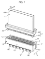
- Fig. 1 is an exploded perspective view of (i) a plug-type connector 2, according to an embodiment of the present invention, to which a pair of FFCs 1, 100 are connected, and (ii) a base connector 3 serving as a receptacle-type connector.
- Fig. 2 is an exploded perspective view of the FFCs 1, 100 and the plug-type connector 2
- Fig. 3 is a section view of the FFC 1.
- the FFC 1 comprises a number of conductors 4 arranged side by side, and insulating films 5 laminated on the both sides of the conductors 4.
- a synthetic resin reinforcing sheet 6 is attached to the backside 1b of an end portion 1a of the FFC 1.
- the reinforcing sheet 6 aligns and holds exposed conductors 4a extending from the end portion 1a of the FFC 1.
- the reinforcing sheet 6 is provided in a pair of lateral edges 6a, 6b thereof with first and second concaved grooves 6c, 6d.
- Each of the concaved grooves 6c, 6d is substantially rectangular for example. Provision is made such that the widths L1, L2 of the first and second concaved grooves 6c, 6d are different from each other with respect to the longitudinal direction of the FFC 1.
- the FFC 100 has an arrangement similar to that of the FFC 1.
- the FFCs 1, 100 are disposed with their backsides being opposite to each other.
- the FFC 100 has a width smaller by a predetermined distance W than the width of the FFC 1. More specifically, the number of the conductors 4 of the FFC 100 is smaller than that of the conductors 4 of the FFC 1.
- the base connector 3 comprises: a base housing 8 which defines an insertion concavity/recess 7, which is made of an insulating synthetic resin, and which is to be attached to the surface Ka of a board K; and two contact rows 9, 90 each having contacts 9a, 9b which pass through the base housing 8 and which are alternately disposed side by side.
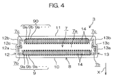
- the base housing 8 has first and second walls 10, 11 opposite to each other, and a pair of lateral walls 12, 13 which connect the opposite ends of the first and second walls 10, 11 to each other. These walls 10 to 13 define the insertion recess 7.
- the side of the base connector 3 at which the first wall 10 is disposed is referred to as the front side X.
- the lateral walls 12, 13 have first portions 12a, 13a between which the distance is relatively wide, and second portions 12b, 13b between which the distance is relatively narrow.
- the lateral walls 12, 13 further have step portions 12c, 13c between the first portions 12a, 13a and the second portions 12b, 13b.
- the insertion recess 7 has a first concavity/recess 7a along the second wall 11, and a pair of second concavities/recesses 7b and a pair of third concavities/recesses 7c which communicate with both ends of the first recess 7a.
- the pair of second recesses 7b are formed at both sides of the contact row 9 and extend along the first portions 12a, 13a of the lateral walls 12, 13.
- the pair of third recesses 7c are formed at both sides of the contact row 90 and extend along the second portions 12b, 13b of the lateral walls 12, 13.
- a plurality of partition walls 14 in the form of a rib of comb teeth are disposed side by side at each of the first and secondwalls 10, 11 defining the insertion recess 7.
- the partition walls 14 extend into the first recess 7a of the insertion recess 7.
- Contact holding grooves 15 which hold corresponding contacts 9a, 9b of the corresponding contact rows 9, 90, are formed between adjacent partition walls 14.
- the contact holding grooves 15 are opened in the first recess 7a of the insertion recess 7.
- the contacts 9a, 9b of the contact row 9 are so disposed as to be opposite to the contacts 9a, 9b of the contact row 90 in the back and forth direction of the base housing 8.
- contact holding holes 16 which hold corresponding contacts 9a, 9b of the corresponding contact rows 9, 90, are formed in the bottom 8a of the base housing 8 at the lower part of the insertion recess 7.
- the contact holding holes 16 communicate with the corresponding contact holding grooves 15.
- Each contact 9a has a long main body 17 housed in a contact holding groove 15, and a projecting portion 18 turned down from the tip of the main body 17 and curved in the form of a mountain.
- the top of the projecting portion 18 forms a contact portion 19 entering inside of the first recess 7a of the insertion recess 7.
- each contact 9a comprises: a press-fitting portion 20 which extends from the main body 17 and which is pressed in a contact holding hole 16; and a lead 21a which extends from the press-fitting portion 20 and which downwardly projects from the base housing 8.
- the alternately disposed contacts 9a, 9b have leads 21a, 21b different from each other only in shape.
- Each lead 21a is made in the form of a hook, while each lead 21b extends substantially straight from the press-fitting portion 20. Accordingly, the leads 21a, 21b are disposed in a zigzag manner with their positions alternately shifted back and forth.
- the leads 21a, 21b pass through the board K and are soldered on the backside Kb thereof.
- the plug-type connector 2 has a holder 22 for holding the end portions 1a of a pair of FFCs 1, 100 and a fixing member 23 for fixing the pair of FFCs 1, 100 to the holder 22.
- the holder 22 comprises: a placing frame 61 formed by connecting mutually parallel first and second placing plates 25, 250 by connecting portions 60; a pair of placing faces 24, 240 formed on the placing plates 25, 250 at their mutually reverse sides; and a pair of holding frames 26, 27 respectively disposed on each of the placing faces 24, 240 at their front sides.
- a recess 62 is formed between the rear end portions of the first and second placing plates 25, 250.
- pulling-outpreventing projections 28 are respectively formed on the placing faces 24, 240 at the rear edge portions 24a thereof. As shown in Figs. 3 and 5, the pulling-out preventing projections 28 are respectively engaged with rear edge portions 6e of the reinforcing sheets 6 of the FFCs 1, 100 placed on the placing faces 24, 240, thus preventing the FFCs 1, 100 from being pulled out.
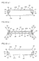
- each pulling-out preventing projection 28 a single long pulling-out preventing proj ection may be disposed on each of the placing faces 24, 240 as shown in Figs. 6(a) and 6(c), or a plurality of pulling-out preventing projections may be disposed at regular intervals.
- Each pulling-out preventing projection 28 fulfills its function as far as it can engage with the reinforcing sheet 6. Accordingly, the projecting amount may be very small (for example, about 0.2 mm).
- Each of the placing faces 24, 240 is provided at both lateral sides thereof with positioning projections 30, 31 engageable with the concaved grooves 6c, 6d (See Fig. 2) of each of the FFCs 1, 100.
- the positioning proj ections 30, 31 have such proper widths as to be just fitted into the concaved grooves 6c, 6d, respectively. This prevents the wrong sides of the FFCs 1, 100 from being respectively placed on the placing faces 24, 240.
- the pair of holding frames 26, 27 disposed on each of the placing faces 24, 240 have lateral frames 51 standing from the lateral edges of each of the placing plates 25, 250, and upper frames 52 inwardly extending from the upper front portions of the lateral frames 51.
- the upper frames 52, the lateral frames 51 and the corresponding placing plates 25, 250 define grooves 32 into which the corresponding lateral edges of the end portions 1a of the FFCs 1, 100 can be introduced.
- projections 33 are formed at the upper rear portions of the lateral frames 51.
- the projections 33 comprise engaged portions 34 with which hooks serving as engagement portions of the fixing member 23 to be discussed later, are engaged.
- the fixing member 23 has an annular portion 37. As shown in Fig. 8, this annular portion 37 defines a substantially rectangular insertion hole 38 into which the placing frame 61 of the holder 22 with the end portions 1a of the FFCs 1, 100 placed thereon, is inserted together with the FFCs 1, 100.
- the annular portion 37 comprises: first and second frames 39, 40 respectively corresponding to the placing faces 24, 240 of the first and second placing plates 25, 250 of the holder 22; and a pair of lateral frames 41, 42 for connecting the opposite ends of the first and second frames 39, 40 to each other.
- These frames 39 to 42 define the insertion hole 38.
- the lateral frames 41, 42 have first portions 41a, 42a between which the distance is relatively wide, and second portions 41b, 42b between which the distance is relatively narrow.
- the lateral frames 41, 42 further comprise step portions 41c, 42c between the first portions 41a, 42a and the second portions 41b, 42b.
- the fixing member 23 has an intermediate frame 63 which is connected to the lateral frames 41, 42 and which extends in parallel to the first and second frames 39, 40.
- the intermediate frame 63 divides the insertion hole 38 into first and second insertion holes 38a, 38b into which the first and second placing plates 25, 250 are respectively inserted.
- Two pairs of engagement portions 43 comprise hooks engageable with the engaged portions 34 of two pairs of projections 33 of the holder 22, and project from a connection-side end face 37a of the annular portion 37.
- cantilevered resilient pieces 44 are formed inside of the first and second walls 39, 40, and the engagement portions 43 comprising hooks are formed at the ends of those projection portions 44a of the resilient pieces 44 which project from the annular portion 37.
- a pair of positioning projections 45 project from the connection-side end face 37a of the annular portion 37.
- the rear part of the holder 22 is inserted into the insertion hole 38 of the annular portion 37 of the fixing member 23, and the engagement portions 43 of the fixing member 23 get over the projections 33 of the holder 22 and then engage with the engagedportions 34.
- the fixing member 23 and the holder 22 are joined to each other to form a plug-type connector 2.
- the first and second placing plates 25, 250 of the holder 22 can respectively be inserted into the first and second insertion holes 38a, 38b of the fixing member 23. Accordingly, the holder 22 and the fixing member 23 can be joined to each other.
- the first placing plate 25 cannot be inserted into the narrower second insertion hole 38b, thus preventing the holder 22 and the fixing member 23 from being joined to each other.
- the insertion projecting portion 2a includes the front parts of the placing plates 25, 250 of the holder 22, the first and second holding frames 26, 27 of the holder 22, and the engagement portions 43 and the positioning projections 45 of the fixing member 23.
- This insertion projecting portion 2a is to be inserted into the insertion recess 7 of the base connector 3 shown in Figs. 4 and 5. More specifically, out of the insertionproj ecting portion 2a, the front parts of the placing plates 25, 250 of the holder 22 are inserted into the first recess 7a (See Fig. 4) of the insertion recess 7, and (i) the first and second holding frames 26, 27 of the holder 22 and (ii) the engagement portions 43 and the positioning projections 45 of the fixing member 23, are inserted into the corresponding second recesses 7b and third recesses 7c (See Fig. 4) of the insertion recess 7.
- an electric connector A is assembled.
- exposed conductors 4a of the FFCs 1,100 connected to the plug-type connector 2 are pressed to and contacted with the contact portions 19 of the corresponding contacts 9a, 9b of the base connector 3, thereby to achieve electric connection.
- the FFCs 1, 100 are previously inserted into the corresponding insertion holes 38a, 38b of the annular portion 37 of the fixing member 23 such that the end portions 1a of the FFCs 1, 100 are temporarily held by the corresponding placing plates 25, 250 of the holder 22 as shown in Fig. 8.
- the end portions 1a of the FFCs 1, 100 and the placing plates 25, 250 are fitted into the annular portion 37 of the fixing member 23, and the engagement portions 43 of the fixing member 23 engage with the engaged portions 34 of the projections 33 of the holder 22 as shown in Fig. 16.
- the plug-type connector 2 can readily be connected to the FFCs 1, 100 as shown in Fig. 1.
- the present invention uses the fixing member 23 having the annular portion 37, thus enabling the FFCs 1, 100 to be stably held.
- the pair of placing plates 25, 250 are connected to each other by the connecting portions 60 to form the placing frame 61.
- the fixingmember 23 is made in the formof a box structure using the first and second frames 39, 40 and the pair of lateral frames 41, 42. This improves the fixing member 23 in strength.
- the plug-type connector 2 can be improved in strength in its entirety.
- the pair of lateral frames 41, 42 are connected to each other by the intermediate frame 63 to further improve the fixing member 23 in strength.
- the intermediate frame 63 of the fixing member 23 is fitted into the recess 62 between the placing plates 25, 250 of the holder 22, and the placing plates 25, 250 are respectively fitted into the insertion holes 38a, 38b at both sides of the intermediate frame 63. This enables the holder 22 and the fixing member 23 to be firmly joined to each other without any backlash or looseness.
- the placing plates 25, 250 of the holder 22 are different from each other in width, and the insertion holes 38a, 38b are also different from each other in width. This prevents the holder 22 from being inversely inserted into the annular portion 37 of the fixing member 23. Further, it is not required to pay special attention to prevention of inverse assembling, thus improving the working efficiency.
- the end portions 1a of the FFCs 1, 100 can be temporarily held as placed on the corresponding placing plates 25, 250 of the holder 22. This improves the working efficiency of connecting the FFCs 1, 100 to the plug-type connector 2. Further, such improvement can be achieved by a simple structure utilizing the reinforcing sheets 6 of the FFCs 1, 100. Further, provision is made such that the FFCs 1, 100 are prevented from being pulled out after assembled.
- the pulling-out preventing projections 28 fulfill their function as far as they can engage with the thin reinforcing sheets 6. Accordingly, the proj ecting amount may be small. Thus, the plug-type connector 2 can be made low in height.
- the positioning proj ections 30, 31 on the placing faces 24, 240 of the placing plates 25, 250 of the holder 22, are engaged with the concaved grooves 6c, 6d in the FFCs 1, 100.
- the concaved grooves 6c, 6d have different widths L1, L2, respectively, thus preventing the FFCs 1, 100 from being inversely placed on the placing plates 25, 250.
- one or more positioningprojections for positioning the front ends of the FFCs 1, 100, may be disposed along the front edge portions 24b (See Figs. 6(a) and 6(c)) of the placing faces 24, 240.
- first and second concaved grooves 6c, 6d of the reinforcing sheets 6 of the FFCs 1, 100 may be eliminated, and the positioning projections 30, 31 of the holder 22 may also be eliminated.
- the present invention may be applied to an electric connector of the side type in which the FFCs 1, 100 are inserted transversely along the surface of a printed board, instead of the type in which the FFCs 1, 100 are inserted from above the printed board.
Landscapes
- Connector Housings Or Holding Contact Members (AREA)
- Coupling Device And Connection With Printed Circuit (AREA)
- Details Of Connecting Devices For Male And Female Coupling (AREA)
Abstract
Description
- The present invention relates to a plug-type connector for connecting an FFC (Flexible Flat Cable), and an electric connector comprising such a plug-type connector.
- Conventionally, an FPC (Flexible Printed Circuit) in the form of a flexible printed circuit board is connected to a base board by connecting a plug-type connector connected to an end of the FPC, to a receptacle-type base connector fixed to the base board.
- For example, in a plug-type connector disclosed in Japanese Unexamined Patent Publication No. 11-329619 (1999), a plug housing is formed by a pair of mutually divided sandwiching members, which are connected to each other with an end of an FPC held by and between these sandwiching members. A fixing pin at one sandwiching member passes through a through-hole formed in the FPC at its widthwise intermediate position. This fixing pin is fitted to the other sandwiching member such that the FPC is securely held in the plug housing.
- Generally, an FFC is smaller in the degree of freedom as to the conductor layout as compared with an FPC. Accordingly, it is difficult to form, in the FFC at its widthwise intermediate position, a through-hole or the like for a fixing pin as mentioned above. That is, the plug-type connector disclosed in the above-mentioned Publication can hardly be applied to FFC connection.
- If the plug-type connector disclosed in the above-mentioned Publication is applied to FFC connection with no fixing pin used, this involves the likelihood that the FFC is unstably held due to variations of dimensional precision and combination precision of the sandwiching members, and the like.
- On the other hand, there is desired a connector capable of collectively connecting a plurality of FFCs.
- It is an object of the present invention to provide a plug-type connector which is capable of readily connecting and securely holding a plurality of FFCs, and also to provide an electric connector comprising such a plug-type connector.
- The present invention provides a plug-type connector for connecting end portions of a pair of FFCs extending in parallel to each other. This plug-type connector comprises: a holder comprising a placing frame provided on the surface and backside thereof with a pair of placing faces on which end portions of a pair of FFCs are respectively placed; and a fixingmember capable of fixing the endportions of the FFCs to the correspondingplacing faces of the holder. The fixing member comprises: an annular portion which defines an insertion hole into which the placing frame of the holder with the end portions of the FFCs placed on the corresponding placing faces, can be inserted together with the FFCs; and engagement portions which are engageable with corresponding engaged portions of the holder when the annular portion is brought toward the holder with the FFCs previously inserted into the insertion hole of the annular portion.
- According to the present invention having the arrangement above-mentioned, with the FFC end portions temporarily held by the corresponding placing faces of the placing frame of the holder, the FFC end portions and the placing frame are fitted into the annular portion of the fixing member such that the engagement portions of the fixing member engage with the engaged portions of the holder. Thus, the pair of FFCs can readily be connected to the plug-type connector. When an FFC is held by and between two sandwichingmembers connected to each other as conventionally done, this involves the likelihood that the FFC is unstably held due to variations of dimensional precision and combination precision of the sandwiching members. On the other hand, the present invention uses the fixing member having the annular portion, thus enabling the FFCs to be stably held.
- The placing frame of the holder may comprise: first and second placing plates respectively provided on the mutually reversesidesthereof with placingfaces;and connecting portions for connecting the first and second placing plates to each other. In this case, the fixing member preferably comprises: first and second frames for holding the ends of the corresponding FFCs in cooperation with the corresponding placing faces; and a pair of lateral frames for connecting the corresponding ends of the first and second frames to each other, the lateral frames and the first and second frames defining the annular portion. According to the arrangement above-mentioned, the pair of placing plates are connected to each other by the connecting portions to form the placing frame. This enables the holder to be improved in strength. Further, the fixing member is made in the form of a box structure using the first and second frames and the pair of lateral frames. This enables the fixing member to be improved in strength. Thus, the plug-type connector can be improved in strength in its entirety.
- The first and second placing plates may be different from each other in width, and the first and second frames may also be different from each other inwidth. This arrangement prevents the placing frame of the holder from being inversely inserted into the annular portion of the fixing member.
- Further, a concavity may be formed between the rear end portions of the first and second placing plates of the holder, and the fixing member may comprise an intermediate frame which connects the pair of lateral frames to each other, which extends inparallel to the first and second frames, andwhich is engageable with the concavity. According to the arrangement above-mentioned, the intermediate frame of the fixing member is fitted into the concavity between the placing plates of the holder, and the first and second placing plates are fitted into the annular portion at both sides of the intermediate frame. This enables the holder and the fixing member to be joined to each other without any backlash or looseness.
- A reinforcing sheet may be attached to the backside of the end portion of each of the FFCs for holding exposed conductors in a row. In this case, a pulling-out preventing projection is preferably formed on each of the placing faces of the holder, this pulling-out preventing projection being engageable with an edge portion of the reinforcing sheet of each of the FFCs. According to the arrangement above-mentioned, before the fixing member is mounted, the FFCs can be temporarily held with their end portions placed on the placing faces of the holder. This improves the working efficiency of connecting the FFCs to the plug-type connector. Further, such improvement can be achieved by a simple structure utilizing the reinforcing sheets of the FFCs. Further, provision is made such that the FFCs are prevented from being pulled out after assembled. The pulling-out preventing projections fulfill their function as far as they can engage with the thin reinforcing sheets. Accordingly, the projecting amount may be small. Thus, the plug-type connector can be made low in height.
- The holder may comprise, on each of the placing faces, a pair of holding frames for defining grooves into which a pair of lateral edges of each of the end portions of the corresponding FFCs, are introduced. In this case, the plug-type connector of the present invention is preferably arranged such that the fixing member comprises a pair of projection portions which proj ect from each of the first and second frames to come in contact with the corresponding holding frames of the holder, that the engagement portions are formed on the projection portions, and that the corresponding holding frames and the proj ectionportions are combined with each other, thus forming a part of an insertion projecting portion to be inserted into an insertion concave of a counter-connector.
- According to the arrangement above-mentioned, the holding frames of the holder and the projection portions of the fixing member, form a part of the insertion projecting portion, which is inserted into the insertion concave of a counter-connector. This assures a secure connector connection. Further, the holding frames and the projection portions not only serve as the insertion projecting portion, but are also utilized for defining the grooves and forming the engagement portions. Thus, the holding frames and the projection portions can fulfill a plurality of functions even though they have a simple structure.
- An electric connector of the present invention comprises: a plug-type connector having the features above-mentioned; and a receptacle-type connector combined with the plug-type connector. The receptacle-type connector comprises: a housing defining an insertion recess into which the insertion projecting portion of the plug-type connector is inserted; and a plurality of contacts arranged side by side in the insertion concave. The present invention can provide an electric connector ideal for connection of a pair of FFCs to a board when used with the receptacle-type connector attached to the board.
- The invention is further described hereinafter, by way of example only, with reference to the accompanying drawings, in which:
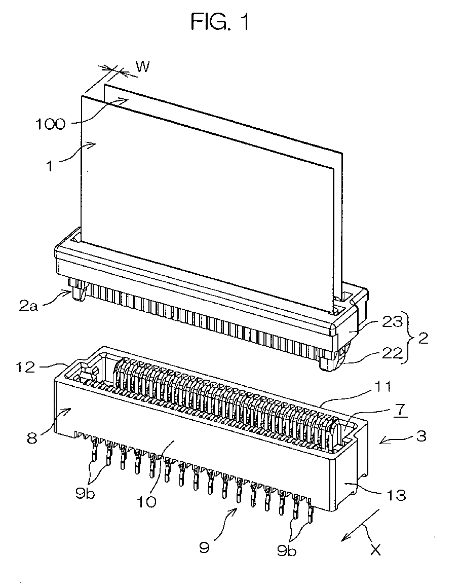
- Fig. 1 is an exploded perspective view of a base connector and a plug-type connector according to an embodiment of the present invention;
- Fig. 2 is an exploded perspective view of the plug-type connector and FFCs:
- Fig. 3 is a schematic section view of the FFC;
- Fig. 4 is a schematic plan view of the base connector;
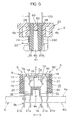
- Fig. 5 is an exploded section view of the plug-type connector and the base connector;
- Fig. 6 (a) , Fig. 6 (b) and Fig. 6 (c) are respectively plan, front and back views of a holder;
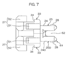
- Fig. 7 is a side view of the holder;
- Fig. 8 is an explodedperspective view of the base connector and the plug-type connector in the course of assembling;
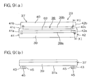
- Fig. 9 (a) is a plan view of a fixing member, and Fig. 9 (b) is a front view of the fixing member;
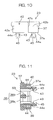
- Fig. 10 is a side view of the fixing member;
- Fig. 11 is a section view taken along the line XI-XI in Fig. 9(a);
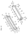
- Fig. 12 is an exploded perspective view of the holder and the fixing member;
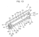
- Fig. 13 is a schematic perspective view of the plug-type connector in which the holder and the fixing member are being assembled with each other;
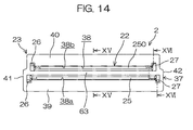
- Fig. 14 is a plan view of the plug-type connector in which the holder and the fixing member are being assembled with each other;
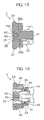
- Fig. 15 is a section view taken along the line XV-XV in Fig. 14;
- Fig. 16 a section view taken along the line XVI-XVI in Fig. 14; and
- Fig. 17 is a section view of the base connector and the plug-type connector connected to each other.
-
- Fig. 1 is an exploded perspective view of (i) a plug-
type connector 2, according to an embodiment of the present invention, to which a pair ofFFCs base connector 3 serving as a receptacle-type connector. Fig. 2 is an exploded perspective view of theFFCs type connector 2, and Fig. 3 is a section view of theFFC 1. - Referring to Figs. 2 and 3, the
FFC 1 comprises a number ofconductors 4 arranged side by side, and insulatingfilms 5 laminated on the both sides of theconductors 4. A syntheticresin reinforcing sheet 6 is attached to thebackside 1b of anend portion 1a of theFFC 1. The reinforcingsheet 6 aligns and holds exposedconductors 4a extending from theend portion 1a of theFFC 1. Referring to Fig. 2, the reinforcingsheet 6 is provided in a pair oflateral edges concaved grooves concaved grooves concaved grooves FFC 1. - The
FFC 100 has an arrangement similar to that of theFFC 1. TheFFCs FFC 100 has a width smaller by a predetermined distance W than the width of theFFC 1. More specifically, the number of theconductors 4 of theFFC 100 is smaller than that of theconductors 4 of theFFC 1. - Referring to Figs. 1 and 5, the
base connector 3 comprises: abase housing 8 which defines an insertion concavity/recess 7, which is made of an insulating synthetic resin, and which is to be attached to the surface Ka of a board K; and twocontact rows contacts base housing 8 and which are alternately disposed side by side. - Referring to Figs. 1 and 4, the
base housing 8 has first andsecond walls lateral walls second walls walls 10 to 13 define theinsertion recess 7. For convenience's sake, the side of thebase connector 3 at which thefirst wall 10 is disposed, is referred to as the front side X. - The
lateral walls first portions second portions lateral walls step portions first portions second portions - Referring to Fig. 4, the
insertion recess 7 has a first concavity/recess 7a along thesecond wall 11, and a pair of second concavities/recesses 7b and a pair of third concavities/recesses 7c which communicate with both ends of thefirst recess 7a. The pair ofsecond recesses 7b are formed at both sides of thecontact row 9 and extend along thefirst portions lateral walls third recesses 7c are formed at both sides of thecontact row 90 and extend along thesecond portions lateral walls - Referring to Figs. 4 and 5, a plurality of
partition walls 14 in the form of a rib of comb teeth are disposed side by side at each of the first andsecondwalls insertion recess 7. Thepartition walls 14 extend into thefirst recess 7a of theinsertion recess 7. Contact holdinggrooves 15 which holdcorresponding contacts corresponding contact rows adjacent partition walls 14. Thecontact holding grooves 15 are opened in thefirst recess 7a of theinsertion recess 7. Thecontacts contact row 9 are so disposed as to be opposite to thecontacts contact row 90 in the back and forth direction of thebase housing 8. - Referring to Fig. 5,
contact holding holes 16 which holdcorresponding contacts corresponding contact rows base housing 8 at the lower part of theinsertion recess 7. The contact holding holes 16 communicate with the correspondingcontact holding grooves 15. - Each
contact 9a has a longmain body 17 housed in acontact holding groove 15, and a projectingportion 18 turned down from the tip of themain body 17 and curved in the form of a mountain. The top of the projectingportion 18 forms acontact portion 19 entering inside of thefirst recess 7a of theinsertion recess 7. Further, eachcontact 9a comprises: a press-fittingportion 20 which extends from themain body 17 and which is pressed in acontact holding hole 16; and a lead 21a which extends from the press-fittingportion 20 and which downwardly projects from thebase housing 8. - The alternately disposed
contacts leads portion 20. Accordingly, theleads leads - Referring to Figs. 1 and 2, the plug-
type connector 2 has aholder 22 for holding theend portions 1a of a pair ofFFCs member 23 for fixing the pair ofFFCs holder 22. - Referring to Figs. 2, 6(a), 6 (b), 6(c), 7 and 12, the
holder 22 comprises: a placingframe 61 formed by connecting mutually parallel first andsecond placing plates portions 60; a pair of placing faces 24, 240 formed on the placingplates frames recess 62 is formed between the rear end portions of the first andsecond placing plates - Referring to Figs. 2, 6 (a) and 6 (c) , pulling-
outpreventing projections 28 are respectively formed on the placing faces 24, 240 at therear edge portions 24a thereof. As shown in Figs. 3 and 5, the pulling-out preventingprojections 28 are respectively engaged withrear edge portions 6e of the reinforcingsheets 6 of theFFCs FFCs - As each pulling-out preventing
projection 28, a single long pulling-out preventing proj ection may be disposed on each of the placing faces 24, 240 as shown in Figs. 6(a) and 6(c), or a plurality of pulling-out preventing projections may be disposed at regular intervals. Each pulling-out preventingprojection 28 fulfills its function as far as it can engage with the reinforcingsheet 6. Accordingly, the projecting amount may be very small (for example, about 0.2 mm). - Each of the placing faces 24, 240 is provided at both lateral sides thereof with
positioning projections concaved grooves FFCs positioning proj ections concaved grooves FFCs - Referring to Figs. 6(a), 6(b), 6(c) and 12, the pair of holding
frames lateral frames 51 standing from the lateral edges of each of the placingplates upper frames 52 inwardly extending from the upper front portions of the lateral frames 51. As shown in Fig. 6(b), theupper frames 52, the lateral frames 51 and thecorresponding placing plates grooves 32 into which the corresponding lateral edges of theend portions 1a of theFFCs - Referring to Figs. 6(a), 6(b), 6(c) and 7,
projections 33 are formed at the upper rear portions of the lateral frames 51. Theprojections 33 comprise engagedportions 34 with which hooks serving as engagement portions of the fixingmember 23 to be discussed later, are engaged. - Referring to Figs. 2, 9 (a) , 9(b), 10, 11 and 12, the fixing
member 23 has anannular portion 37. As shown in Fig. 8, thisannular portion 37 defines a substantiallyrectangular insertion hole 38 into which theplacing frame 61 of theholder 22 with theend portions 1a of theFFCs FFCs - Referring to Figs. 9 (a) and 9(b), the
annular portion 37 comprises: first andsecond frames second placing plates holder 22; and a pair oflateral frames second frames frames 39 to 42 define theinsertion hole 38. The lateral frames 41, 42 havefirst portions second portions step portions 41c, 42c between thefirst portions second portions - The fixing
member 23 has anintermediate frame 63 which is connected to the lateral frames 41, 42 and which extends in parallel to the first andsecond frames intermediate frame 63 divides theinsertion hole 38 into first andsecond insertion holes second placing plates - Two pairs of
engagement portions 43 comprise hooks engageable with the engagedportions 34 of two pairs ofprojections 33 of theholder 22, and project from a connection-side end face 37a of theannular portion 37. As shown in Figs. 10 and 11 which is a section view taken along the line XI - XI in Fig. 9 (a) , cantileveredresilient pieces 44 are formed inside of the first andsecond walls engagement portions 43 comprising hooks are formed at the ends of thoseprojection portions 44a of theresilient pieces 44 which project from theannular portion 37. - Referring to Figs. 9 (a) , 9 (b) and 10 - 16, in the vicinity of the inner sides of each pair of
engagement portions 43, a pair ofpositioning projections 45 project from the connection-side end face 37a of theannular portion 37. - Referring to Figs. 12 and 13, the rear part of the
holder 22 is inserted into theinsertion hole 38 of theannular portion 37 of the fixingmember 23, and theengagement portions 43 of the fixingmember 23 get over theprojections 33 of theholder 22 and then engage with theengagedportions 34. Thus, the fixingmember 23 and theholder 22 are joined to each other to form a plug-type connector 2. - As shown in Fig. 2, when the
holder 22 and the fixingmember 23 properly face each other, the first andsecond placing plates holder 22 can respectively be inserted into the first andsecond insertion holes member 23. Accordingly, theholder 22 and the fixingmember 23 can be joined to each other. On the other hand, when theholder 22 and the fixingmember 23 do not properly face each other, thefirst placing plate 25 cannot be inserted into the narrowersecond insertion hole 38b, thus preventing theholder 22 and the fixingmember 23 from being joined to each other. - As shown in Fig. 13, the tips of both the
engagement portions 43 and thepositioning projections 45 of the fixingmember 23, come in contact with the correspondingupper frames 52 of theholder 22 to properly position the fixingmember 23 and theholder 22. - In the assembly state of the plug-
type connector 2 shown in Fig. 13, that portion of the fixingmember 23 which projects forwardly from the connection-side end face 37a of theannular portion 37, forms aninsertion projecting portion 2a of the plug-type connector 2. More specifically, theinsertion projecting portion 2a includes the front parts of the placingplates holder 22, the first and second holding frames 26, 27 of theholder 22, and theengagement portions 43 and thepositioning projections 45 of the fixingmember 23. - This
insertion projecting portion 2a is to be inserted into theinsertion recess 7 of thebase connector 3 shown in Figs. 4 and 5. More specifically, out of the insertionproj ectingportion 2a, the front parts of the placingplates holder 22 are inserted into thefirst recess 7a (See Fig. 4) of theinsertion recess 7, and (i) the first and second holding frames 26, 27 of theholder 22 and (ii) theengagement portions 43 and thepositioning projections 45 of the fixingmember 23, are inserted into the correspondingsecond recesses 7b andthird recesses 7c (See Fig. 4) of theinsertion recess 7. Thus, as shown in Fig. 17, an electric connector A is assembled. In the electric connector A, exposedconductors 4a of the FFCs 1,100 connected to the plug-type connector 2, are pressed to and contacted with thecontact portions 19 of thecorresponding contacts base connector 3, thereby to achieve electric connection. - As to the connection of the
FFCs type connector 2, theFFCs corresponding insertion holes annular portion 37 of the fixingmember 23 such that theend portions 1a of theFFCs corresponding placing plates holder 22 as shown in Fig. 8. At this state, theend portions 1a of theFFCs plates annular portion 37 of the fixingmember 23, and theengagement portions 43 of the fixingmember 23 engage with the engagedportions 34 of theprojections 33 of theholder 22 as shown in Fig. 16. In this manner, the plug-type connector 2 can readily be connected to theFFCs - When an FFC is held by and between two sandwiching members connected to each other as conventionally done, this involves the likelihood that the FFC is unstably held due to variations of dimensional precision and combination precision of the sandwiching members. On the other hand, the present invention uses the fixing
member 23 having theannular portion 37, thus enabling theFFCs - Further, the pair of placing
plates portions 60 to form the placingframe 61. This enables theholder 22 to be improved in strength. Further, thefixingmember 23 is made in the formof a box structure using the first andsecond frames lateral frames member 23 in strength. Thus, the plug-type connector 2 can be improved in strength in its entirety. - In particular, the pair of
lateral frames intermediate frame 63 to further improve the fixingmember 23 in strength. In addition, as shown in Fig. 15, when theholder 22 and the fixingmember 23 are joined to each other, theintermediate frame 63 of the fixingmember 23 is fitted into therecess 62 between the placingplates holder 22, and the placingplates insertion holes intermediate frame 63. This enables theholder 22 and the fixingmember 23 to be firmly joined to each other without any backlash or looseness. - Further, the placing
plates holder 22 are different from each other in width, and theinsertion holes holder 22 from being inversely inserted into theannular portion 37 of the fixingmember 23. Further, it is not required to pay special attention to prevention of inverse assembling, thus improving the working efficiency. - Further, as shown in Fig. 8, before the fixing
member 23 is mounted, theend portions 1a of theFFCs corresponding placing plates holder 22. This improves the working efficiency of connecting theFFCs type connector 2. Further, such improvement can be achieved by a simple structure utilizing the reinforcingsheets 6 of theFFCs FFCs projections 28 fulfill their function as far as they can engage with the thin reinforcingsheets 6. Accordingly, the proj ecting amount may be small. Thus, the plug-type connector 2 can be made low in height. - Further, the
positioning proj ections plates holder 22, are engaged with theconcaved grooves FFCs plates FFCs concaved grooves FFCs plates - The present invention should not be limited to the embodiments above-mentioned. For example, one or more positioningprojections (not shown) for positioning the front ends of the
FFCs front edge portions 24b (See Figs. 6(a) and 6(c)) of the placing faces 24, 240. - Further, the first and second
concaved grooves sheets 6 of theFFCs positioning projections holder 22 may also be eliminated. - The present invention may be applied to an electric connector of the side type in which the
FFCs FFCs - Embodiments of the present invention have been discussed in detail, but these embodiments are mere specific examples for clarifying the technical contents of the present invention. Therefore, the present invention should not be construed as limited to these specific examples. The scope of the present invention is limited only by the appended claims.
Claims (7)
- A plug-type connector (2) for connecting end portions of a pair of FFCs (1, 100) extending in parallel to each other, comprising:a holder (22) including a placing frame (61) provided on a surface and backside thereof with a pair of placing faces (24, 240) on which end portions of the pair of FFCs (1, 100) are respectively placed; anda fixing member (23) capable of fixing the end portions of the pair of FFCs (1, 100) to the corresponding placing faces (24, 240) of the holder (22),the fixing member (23) including:an annular portion (37) which defines an insertion hole (38) into which the placing frame (61) of the holder (22) with the end portions of the FFCs (1, 100) placed on the corresponding placing faces (24, 240) , can be inserted together with the FFCs (1, 100); andengagement portions (43) which are engageable with corresponding engaged portions (34) of the holder (22) when the annular portion (37) is brought toward the holder (22) with the pair of FFCs (1, 100) previously inserted into the insertion hole (38) of the annular portion (37).
- A plug-type connector according to Claim 1, wherein
the placing frame (61) of the holder (22) includes: first and second placing plates (25, 250) respectively provided on mutually reverse sides thereof with the corresponding placing faces (24, 240); and connecting portions (60) for connecting the first and second placing plates (25, 250) to each other,
the fixing member (23) includes: first and second frames (39, 40) for holding the ends of the corresponding FFCs (1, 100) between the first and second frames (39, 40) and the corresponding placing faces (24, 240); and a pair of lateral frames (41, 42) for connecting corresponding ends of the first and second frames (39, 40) to each other, the lateral frames (41, 42) and the first and second frames (39, 40) defining the annular portion (37). - A plug-type connector according to Claim 2, wherein the first and second placing plates (25, 250) are different from each other in width, and the first and second frames (39, 40) are different from each other in width.
- A plug-type connector according to any of Claims 2 to 3, wherein
a recess (62) is formed between rear end portions of the first and second placing plates (25, 250) of the holder (22), and
the fixing member (23) further includes an intermediate frame (63) which connects the pair of lateral frames (41, 42) to each other, which extends in parallel to the first and second frames (39, 40) , and which is engageable with the recess (62). - A plug-type connector according to any of Claims 2 to 4, wherein
the holder (22) includes, on each of the placing faces (24, 240), a pair of holding frames (26, 27) for defining grooves (32) into which a pair of lateral edges of each of the end portions of the corresponding FFCs (1, 100), can be introduced,
the fixing member (23) includes a pair of projection portions (44a, 45) which proj ect from each of the first and second frames (39, 40) to come in contact with the corresponding holding frames (26, 27) of the holder (22),
the engagement portions (43) are respectively formed on the projection portions (44a, 45), and
the holding frames (26, 27) and the corresponding projection portions (44a, 45) are combined with each other, thus forming a part of an insertion projecting portion (2a) to be inserted into an insertion recess (7) of a mating connector (3). - A plug-type connector according to any of Claims 1 to 5, wherein
a reinforcing sheet (6) is attached to backside of the end portion of each FFC (1, 100) for holding exposed conductors (4a) in a row, and
a pulling-out preventing proj ection (28) is formed on each of the placing faces (24, 240) of the holder (22) , the pulling-out preventing proj ection (28) being engageable with an edge portion of the reinforcing sheet (6) of each FFC (1,100). - An electric connector (A) comprising:a plug-type connector (2) according to any of Claims 1 to 6; anda receptacle-type connector (3) combined with the plug-type connector (2),the plug-type connector (2) having an insertion projecting portion (2a) to be inserted into an insertion recess (7) of the receptacle-type connector (3), andthe receptacle-type connector (3) including: a housing (8) defining the insertion recess (7) into which the insertion projecting portion (2a) of the plug-type connector (2) is inserted; and a plurality of contacts (9a, 9b) arranged side by side in the insertion recess (7).
Applications Claiming Priority (2)
| Application Number | Priority Date | Filing Date | Title |
|---|---|---|---|
| JP2003164057A JP2005004994A (en) | 2003-06-09 | 2003-06-09 | Plug-type connector and electrical connector including the same |
| JP2003164057 | 2003-06-09 |
Publications (3)
| Publication Number | Publication Date |
|---|---|
| EP1489697A2 true EP1489697A2 (en) | 2004-12-22 |
| EP1489697A3 EP1489697A3 (en) | 2009-01-21 |
| EP1489697A9 EP1489697A9 (en) | 2009-07-01 |
Family
ID=33410879
Family Applications (1)
| Application Number | Title | Priority Date | Filing Date |
|---|---|---|---|
| EP04253233A Withdrawn EP1489697A3 (en) | 2003-06-09 | 2004-05-29 | Plug-type connector and its counterpart |
Country Status (6)
| Country | Link |
|---|---|
| US (1) | US7128596B2 (en) |
| EP (1) | EP1489697A3 (en) |
| JP (1) | JP2005004994A (en) |
| KR (1) | KR20040105566A (en) |
| CN (1) | CN100359765C (en) |
| TW (1) | TWI236783B (en) |
Cited By (1)
| Publication number | Priority date | Publication date | Assignee | Title |
|---|---|---|---|---|
| EP3118935A1 (en) * | 2015-07-14 | 2017-01-18 | odelo GmbH | Electrical contacting of flex circuit boards in vehicle lights |
Families Citing this family (22)
| Publication number | Priority date | Publication date | Assignee | Title |
|---|---|---|---|---|
| USD526277S1 (en) * | 2003-06-06 | 2006-08-08 | Hon Hai Precision Ind. Co., Ltd. | Interface of an electrical connector |
| TWD103912S1 (en) * | 2004-03-26 | 2005-04-01 | 日本壓著端子製造股份有限公司 | Electrical connector |
| TWD105398S1 (en) * | 2004-03-26 | 2005-07-01 | 日本壓著端子製造股份有限公司 | Electrical connector |
| TWM269683U (en) * | 2005-01-03 | 2005-07-01 | High Tech Comp Corp | Flexible printed circuit board and reinforcing structure thereof |
| USD539747S1 (en) * | 2005-11-08 | 2007-04-03 | Yamaichi Electronics Co. Ltd. | Electrical connector |
| JP4818833B2 (en) | 2006-06-30 | 2011-11-16 | 日本圧着端子製造株式会社 | Flat flexible cable harness |
| US7717767B2 (en) * | 2007-04-16 | 2010-05-18 | Ridemakerz, Llc | Modular toy vehicle accessory mounts |
| CN101533971B (en) * | 2008-03-11 | 2011-12-14 | 富士康(昆山)电脑接插件有限公司 | Cable connector component and flexible flat cable module thereof |
| JP5458842B2 (en) | 2009-12-02 | 2014-04-02 | ソニー株式会社 | Remote control device, remote control system, remote control method and program |
| KR101133954B1 (en) * | 2010-07-20 | 2012-04-05 | (주)우주일렉트로닉스 | Connector For Flat Cable |
| USD703143S1 (en) * | 2012-04-23 | 2014-04-22 | Japan Aviation Electronics Industry, Limited | Electrical connector |
| USD706222S1 (en) * | 2012-08-10 | 2014-06-03 | Japan Aviation Electronics Industry, Limited | Electrical connector |
| JP6352676B2 (en) * | 2014-05-13 | 2018-07-04 | モレックス エルエルシー | connector |
| CN111834772B (en) * | 2014-12-05 | 2022-03-01 | 松下知识产权经营株式会社 | Plug connectors and connector sets |
| WO2017053675A1 (en) * | 2015-09-23 | 2017-03-30 | Molex, Llc | Plug assembly and receptacle assembly with two rows |
| CN105161882A (en) * | 2015-10-23 | 2015-12-16 | 亳州联滔电子有限公司 | Cable connector assembly |
| CN109417242B (en) | 2016-05-16 | 2022-10-04 | 莫列斯有限公司 | high density socket |
| JP6859670B2 (en) * | 2016-11-11 | 2021-04-14 | セイコーエプソン株式会社 | Liquid discharge head |
| US11483928B2 (en) * | 2017-08-14 | 2022-10-25 | Sumitomo Electric Printed Circuits, Inc. | Flexible printed circuit board |
| KR102516102B1 (en) | 2017-11-28 | 2023-03-29 | 몰렉스 엘엘씨 | High speed connector |
| JP2019140356A (en) * | 2018-02-15 | 2019-08-22 | シャープ株式会社 | Flexible circuit board |
| CN109216977B (en) * | 2018-09-25 | 2020-07-03 | 青岛科技大学 | An electrical connection device for a circuit board |
Citations (3)
| Publication number | Priority date | Publication date | Assignee | Title |
|---|---|---|---|---|
| US3278887A (en) * | 1964-03-16 | 1966-10-11 | Westinghouse Electric Corp | Electrical circuit assembly and method of manufacture |
| EP1235304A1 (en) * | 2001-02-22 | 2002-08-28 | Yazaki Corporation | Connector for flat circuit member |
| JP2003157928A (en) * | 2001-11-20 | 2003-05-30 | Auto Network Gijutsu Kenkyusho:Kk | Connector for flat wiring material |
Family Cites Families (8)
| Publication number | Priority date | Publication date | Assignee | Title |
|---|---|---|---|---|
| JPH11329619A (en) * | 1998-03-13 | 1999-11-30 | Denso Corp | FPC connector |
| US6254435B1 (en) * | 1999-06-01 | 2001-07-03 | Molex Incorporated | Edge card connector for a printed circuit board |
| CN2452171Y (en) * | 2000-05-26 | 2001-10-03 | 富士康(昆山)电脑接插件有限公司 | Cable connector assembly |
| US6273753B1 (en) * | 2000-10-19 | 2001-08-14 | Hon Hai Precision Ind. Co., Ltd. | Twinax coaxial flat cable connector assembly |
| JP3687548B2 (en) * | 2001-02-16 | 2005-08-24 | 住友電装株式会社 | Waterproof connector for flexible flat cable |
| US6860755B2 (en) * | 2001-09-12 | 2005-03-01 | Hung-Jen Chiu | Bus cable connector having terminal tail sections positioned by ribs |
| US6520810B1 (en) * | 2001-10-24 | 2003-02-18 | Molex Incorporated | Connector system for interconnection with flat flexible circuitry |
| TW534493U (en) * | 2002-06-20 | 2003-05-21 | Hon Hai Prec Ind Co Ltd | Electrical connector |
-
2003
- 2003-06-09 JP JP2003164057A patent/JP2005004994A/en active Pending
-
2004
- 2004-05-24 TW TW093114620A patent/TWI236783B/en not_active IP Right Cessation
- 2004-05-29 EP EP04253233A patent/EP1489697A3/en not_active Withdrawn
- 2004-06-04 US US10/860,136 patent/US7128596B2/en not_active Expired - Fee Related
- 2004-06-04 KR KR1020040040815A patent/KR20040105566A/en not_active Ceased
- 2004-06-08 CN CNB2004100485704A patent/CN100359765C/en not_active Expired - Fee Related
Patent Citations (3)
| Publication number | Priority date | Publication date | Assignee | Title |
|---|---|---|---|---|
| US3278887A (en) * | 1964-03-16 | 1966-10-11 | Westinghouse Electric Corp | Electrical circuit assembly and method of manufacture |
| EP1235304A1 (en) * | 2001-02-22 | 2002-08-28 | Yazaki Corporation | Connector for flat circuit member |
| JP2003157928A (en) * | 2001-11-20 | 2003-05-30 | Auto Network Gijutsu Kenkyusho:Kk | Connector for flat wiring material |
Cited By (1)
| Publication number | Priority date | Publication date | Assignee | Title |
|---|---|---|---|---|
| EP3118935A1 (en) * | 2015-07-14 | 2017-01-18 | odelo GmbH | Electrical contacting of flex circuit boards in vehicle lights |
Also Published As
| Publication number | Publication date |
|---|---|
| TWI236783B (en) | 2005-07-21 |
| CN100359765C (en) | 2008-01-02 |
| JP2005004994A (en) | 2005-01-06 |
| EP1489697A3 (en) | 2009-01-21 |
| KR20040105566A (en) | 2004-12-16 |
| US7128596B2 (en) | 2006-10-31 |
| EP1489697A9 (en) | 2009-07-01 |
| US20040248450A1 (en) | 2004-12-09 |
| CN1574477A (en) | 2005-02-02 |
| TW200503334A (en) | 2005-01-16 |
Similar Documents
| Publication | Publication Date | Title |
|---|---|---|
| EP1487061B1 (en) | Plug-type connector and electric connector comprising the same | |
| US7128596B2 (en) | Plug-type connector and electric connector comprising the same | |
| JP7445703B2 (en) | connector | |
| US9847604B2 (en) | Electrical connector having improved shielding structure | |
| CN100361352C (en) | Connector with a locking member | |
| JPH06208874A (en) | Electrical connector for card reader | |
| EP1337009B1 (en) | A shielding connector, a shielding connector system, a terminal fitting and use thereof | |
| US7217158B2 (en) | Electrical connector | |
| US20080032560A1 (en) | Electrical connector assembly | |
| EP1235303B1 (en) | A connector terminal and a method for producing the same | |
| US7086889B2 (en) | Interlocking member for an electrical connector | |
| US20110235293A1 (en) | Shield case, connector and electronic equipment | |
| CN111525307A (en) | Dual connector assembly for circuit boards | |
| JPH10106693A (en) | Cable connector assembly and its manufacture | |
| JP3622946B2 (en) | connector | |
| US20090233462A1 (en) | Cable connector assembly with FFC module | |
| EP1965469A2 (en) | Electrical connector | |
| JP2822305B2 (en) | Connector structure | |
| JP2000150054A (en) | Joint connector | |
| JP2002289287A (en) | Shared connector and method of manufacturing the same | |
| JP3637859B2 (en) | Flat cable connector | |
| EP1601064A1 (en) | Board attachment-type electrical connector | |
| JP2548757Y2 (en) | Electrical connector for circuit board | |
| JP4602050B2 (en) | Multi-connection type header connector and vertical socket connector and horizontal socket connector connected to this | |
| JP3473897B2 (en) | Electrical junction box |
Legal Events
| Date | Code | Title | Description |
|---|---|---|---|
| PUAI | Public reference made under article 153(3) epc to a published international application that has entered the european phase |
Free format text: ORIGINAL CODE: 0009012 |
|
| AK | Designated contracting states |
Kind code of ref document: A2 Designated state(s): AT BE BG CH CY CZ DE DK EE ES FI FR GB GR HU IE IT LI LU MC NL PL PT RO SE SI SK TR |
|
| AX | Request for extension of the european patent |
Extension state: AL HR LT LV MK |
|
| PUAL | Search report despatched |
Free format text: ORIGINAL CODE: 0009013 |
|
| AK | Designated contracting states |
Kind code of ref document: A3 Designated state(s): AT BE BG CH CY CZ DE DK EE ES FI FR GB GR HU IE IT LI LU MC NL PL PT RO SE SI SK TR |
|
| AX | Request for extension of the european patent |
Extension state: AL HR LT LV MK |
|
| 17P | Request for examination filed |
Effective date: 20090417 |
|
| RTI1 | Title (correction) |
Free format text: PLUG-TYPE CONNECTOR ELECTRIC CONNECTOR COMPRISING THE SAME |
|
| RTI1 | Title (correction) |
Free format text: PLUG-TYPE CONNECTOR AND ELECTRIC CONNECTOR COMPRISING THE SAME |
|
| AKX | Designation fees paid |
Designated state(s): DE FR GB |
|
| 17Q | First examination report despatched |
Effective date: 20111215 |
|
| STAA | Information on the status of an ep patent application or granted ep patent |
Free format text: STATUS: THE APPLICATION IS DEEMED TO BE WITHDRAWN |
|
| 18D | Application deemed to be withdrawn |
Effective date: 20120426 |