EP1489356A1 - Waste treatment apparatus and method - Google Patents
Waste treatment apparatus and method Download PDFInfo
- Publication number
- EP1489356A1 EP1489356A1 EP04022569A EP04022569A EP1489356A1 EP 1489356 A1 EP1489356 A1 EP 1489356A1 EP 04022569 A EP04022569 A EP 04022569A EP 04022569 A EP04022569 A EP 04022569A EP 1489356 A1 EP1489356 A1 EP 1489356A1
- Authority
- EP
- European Patent Office
- Prior art keywords
- combustion furnace
- exhaust gas
- fly ash
- slagging combustion
- slagging
- Prior art date
- Legal status (The legal status is an assumption and is not a legal conclusion. Google has not performed a legal analysis and makes no representation as to the accuracy of the status listed.)
- Withdrawn
Links
Images

Classifications
-
- F—MECHANICAL ENGINEERING; LIGHTING; HEATING; WEAPONS; BLASTING
- F23—COMBUSTION APPARATUS; COMBUSTION PROCESSES
- F23G—CREMATION FURNACES; CONSUMING WASTE PRODUCTS BY COMBUSTION
- F23G5/00—Incineration of waste; Incinerator constructions; Details, accessories or control therefor
- F23G5/02—Incineration of waste; Incinerator constructions; Details, accessories or control therefor with pretreatment
- F23G5/027—Incineration of waste; Incinerator constructions; Details, accessories or control therefor with pretreatment pyrolising or gasifying stage
-
- F—MECHANICAL ENGINEERING; LIGHTING; HEATING; WEAPONS; BLASTING
- F23—COMBUSTION APPARATUS; COMBUSTION PROCESSES
- F23J—REMOVAL OR TREATMENT OF COMBUSTION PRODUCTS OR COMBUSTION RESIDUES; FLUES
- F23J15/00—Arrangements of devices for treating smoke or fumes
- F23J15/02—Arrangements of devices for treating smoke or fumes of purifiers, e.g. for removing noxious material
- F23J15/022—Arrangements of devices for treating smoke or fumes of purifiers, e.g. for removing noxious material for removing solid particulate material from the gasflow
- F23J15/025—Arrangements of devices for treating smoke or fumes of purifiers, e.g. for removing noxious material for removing solid particulate material from the gasflow using filters
-
- F—MECHANICAL ENGINEERING; LIGHTING; HEATING; WEAPONS; BLASTING
- F23—COMBUSTION APPARATUS; COMBUSTION PROCESSES
- F23G—CREMATION FURNACES; CONSUMING WASTE PRODUCTS BY COMBUSTION
- F23G2202/00—Combustion
- F23G2202/10—Combustion in two or more stages
- F23G2202/104—Combustion in two or more stages with ash melting stage
-
- F—MECHANICAL ENGINEERING; LIGHTING; HEATING; WEAPONS; BLASTING
- F23—COMBUSTION APPARATUS; COMBUSTION PROCESSES
- F23G—CREMATION FURNACES; CONSUMING WASTE PRODUCTS BY COMBUSTION
- F23G2202/00—Combustion
- F23G2202/10—Combustion in two or more stages
- F23G2202/106—Combustion in two or more stages with recirculation of unburned solid or gaseous matter into combustion chamber
-
- F—MECHANICAL ENGINEERING; LIGHTING; HEATING; WEAPONS; BLASTING
- F23—COMBUSTION APPARATUS; COMBUSTION PROCESSES
- F23G—CREMATION FURNACES; CONSUMING WASTE PRODUCTS BY COMBUSTION
- F23G2206/00—Waste heat recuperation
-
- F—MECHANICAL ENGINEERING; LIGHTING; HEATING; WEAPONS; BLASTING
- F23—COMBUSTION APPARATUS; COMBUSTION PROCESSES
- F23G—CREMATION FURNACES; CONSUMING WASTE PRODUCTS BY COMBUSTION
- F23G2209/00—Specific waste
- F23G2209/30—Solid combustion residues, e.g. bottom or flyash
-
- Y—GENERAL TAGGING OF NEW TECHNOLOGICAL DEVELOPMENTS; GENERAL TAGGING OF CROSS-SECTIONAL TECHNOLOGIES SPANNING OVER SEVERAL SECTIONS OF THE IPC; TECHNICAL SUBJECTS COVERED BY FORMER USPC CROSS-REFERENCE ART COLLECTIONS [XRACs] AND DIGESTS
- Y02—TECHNOLOGIES OR APPLICATIONS FOR MITIGATION OR ADAPTATION AGAINST CLIMATE CHANGE
- Y02E—REDUCTION OF GREENHOUSE GAS [GHG] EMISSIONS, RELATED TO ENERGY GENERATION, TRANSMISSION OR DISTRIBUTION
- Y02E50/00—Technologies for the production of fuel of non-fossil origin
- Y02E50/30—Fuel from waste, e.g. synthetic alcohol or diesel
Definitions
- the present invention relates to waste treatment apparatus and method, and more particularly to waste treatment apparatus and method for combusting and treating wastes such as municipal wastes, refuse-derived fuel (RDF), plastic wastes, waste FRP, biomass wastes, automobile wastes and waste oil.
- wastes such as municipal wastes, refuse-derived fuel (RDF), plastic wastes, waste FRP, biomass wastes, automobile wastes and waste oil.
- the present invention also relates to two-stage gasification apparatus and method comprising a fluidized-bed gasification furnace and a swirling-type slagging combustion gasification furnace.
- waste treatment method there has been known a method in which wastes are pyrolyzed and gasified at a low temperature in a gasification furnace to produce combustible gas, the produced combustible gas is supplied to a slagging combustion furnace, and then the produced combustion gas is combusted at a high temperature to melt solid components contained in the produced combustion gas and recover slag from a bottom of the slagging combustion furnace.
- Exhaust gas generated by combustion in the slagging combustion furnace is led to a waste heat boiler in which steam is generated by heat exchange with the exhaust gas for thereby recovering heat from the exhaust gas.
- the exhaust gas discharged from the waste heat boiler is led to a first bag filter in which ash contained in the exhaust gas is collected.
- the collected ash is treated by a slagging pyrolysis process, or is treated by a neutralization process using slaked lime, and is then discarded in a landfill site.
- the exhaust gas discharged from the first bag filter is neutralized by mixing slaked lime, and then the exhaust gas is led to a second bag filter in which neutralized ash is collected.
- the present invention has been made in view of the above drawbacks. It is therefore an object of the present invention to provide waste treatment apparatus and method which can increase the percentage of slagging, reduce the amount of the collected ash required to be neutralized, and reduce the amount of neutralizer to be used.
- a waste treatment apparatus comprising: a gasification furnace for gasifying wastes to produce combustible gas; a slagging combustion furnace for combusting the combustible gas and melting solid components contained in the combustible gas to generate exhaust gas; a first filter for filtrating the exhaust gas discharged from the slagging combustion furnace and collecting fly ash contained in the exhaust gas; an injection device for injecting a neutralizer into the exhaust gas discharged from the first filter; a second filter for filtrating the exhaust gas into which the neutralizer has been injected, and collecting'neutralized ash contained in the exhaust gas; a recovery device for recovering the neutralized ash which has been collected; and a conveying device for conveying fly ash collected by the first filter to the slagging combustion furnace.
- the first filter 13a, the second filter 13b, the injection device 14, the conveying decide 41a, and the recovery device 17 are provided.
- exhaust gas j is filtrated by the first filter 13a
- fly ash h1 collected by the first filter 13a is conveyed by the conveying device 41a and returned to the slagging combustion furnace 8
- a neutralizer i is injected into the exhaust gas j discharged from the first filter 13a by the injection device 14, the exhaust gas j into which the neutralizer i has been injected is filtrated by the second filter 13b to collect the neutralized ash h2, and the collected the neutralized ash h2 is recovered by the recovery device 17.
- the fly ash h1 collected by the first filter 13a is conveyed to the slagging combustion furnace 8, and hence the fly ash h1 is melted in the slagging combustion furnace 8 to thus increase the percentage of slagging in the slagging combustion furnace 8, and the collected ash which requires neutralization treatment can be decreased. Further, after the fly ash h1 is collected in the first filter 13a, the neutralizer i is injected into the exhaust gas j, and hence the amount of the neutralizer i to be used can be decreased and the amount of neutralized ash h2 can be decreased.
- fly ash h1 which does not contain the neutralized ash h2 is conveyed to the slagging combustion furnace 8, the fly ash h1 can be efficiently melted and treated. Further, since the exhaust gas j which does not contain components of the neutralizer i is discharged from the slagging combustion furnace 8, and the fly ash h1 collected by the first filter 13a does not contain components of the neutralizer i, slag e having a high quality can be produced.
- a waste treatment apparatus further comprises a waste heat boiler for recovering thermal energy of the exhaust gas discharged from the slagging combustion furnace, and a conveying device for conveying fly ash collected by the waste heat boiler to the slagging combustion furnace.
- the conveying device 41b because the conveying device 41b is provided, the fly ash h1 collected by the waste heat boiler 10 is conveyed to the slagging combustion furnace 8 by the conveying device 41b, and melted in the slagging combustion furnace 8, thus further increasing the percentage of slagging in the slagging combustion furnace 8.
- a waste treatment apparatus further comprises an economizer for preheating water to be fed to the waste heat boiler by thermal energy of the exhaust gas discharged from the waste heat boiler, and a conveying device for conveying fly ash collected by the economizer to the slagging combustion furnace.
- the conveying device 41c because the conveying device 41c is provided, the fly ash h1 collected by the economizer 12 is conveyed to the slagging combustion furnace 8 by the conveying device 41c, and melted in the slagging combustion furnace 8, thus further increasing the percentage of slagging in the slagging combustion furnace 8.
- a waste treatment apparatus further comprises an air preheater for preheating combustion air to be fed to the gasification furnace and the slagging combustion furnace by thermal energy of the exhaust gas discharged from the waste heat boiler, and a conveying device for conveying fly ash collected by the air preheater to the slagging combustion furnace.
- the conveying device 41c because the conveying device 41c is provided, the fly ash h1 collected by the air preheater 11 is conveyed to the slagging combustion furnace 8 by the conveying device 41c, and melted in the slagging combustion furnace 8, thus further increasing the percentage of slagging in the slagging combustion furnace 8.
- a waste treatment apparatus further comprises an introduction device for introducing the fly ash conveyed to the slagging combustion furnace into the slagging combustion furnace in a direction along an inner circumferential surface of the slagging combustion furnace.
- the fly ash h1 conveyed to the slagging combustion furnace 8 can be introduced into the slagging combustion furnace in a direction along an inner circumferential surface 8e of the slagging combustion furnace to form a swirling flow in the slagging combustion furnace 8, and the fly ash h1 can be efficiently melted and the percentage of slagging in the slagging combustion furnace 8 can be further increased.
- a waste treatment apparatus comprising: a gasification furnace for gasifying wastes to produce combustible gas; a slagging combustion furnace for combusting the combustible gas and melting solid components contained in the combustible gas to generate exhaust gas; a filter for filtrating the exhaust gas discharged from the slagging combustion furnace and collecting fly ash contained in the exhaust gas; a conveying device for conveying the fly ash collected by the filter to the slagging combustion furnace; and an introduction device for introducing the fly ash conveyed to the slagging combustion furnace into the slagging combustion furnace.
- the filter 13a, the conveying device 41a and the introduction device 23 are provided, exhaust gas j is filtrated by the filter 13a, the collected fly ash h1 is conveyed to the slagging combustion furnace 8 by the conveying device 41a, the conveyed fly ash h1 can be introduced into the slagging combustion furnace 8 in a direction along the inner circumferential surface 8e of the slagging combustion furnace 8 by the introduction device 23 to form a swirling flow in the slagging combustion furnace 8, and the fly ash h1 can be efficiently melted and the percentage of slagging in the slagging combustion furnace 8 can be further increase.
- the introduction device is mounted on the slagging combustion furnace at a location where the combustible gas which has not been combusted exists.
- the introduction devices 22 and 23 are mounted on the slagging combustion furnace 8 at the location where combustible gas m supplied from the gasification furnace 5 exists and such combustible gas has not been combusted, the introduced fly ash h1 is conveyed by the flow of the combustible gas m to the flame formed by combustion in the slagging combustion furnace 8, and hence the fly ash h1 is exposed to the maximum temperature range. Therefore, the fly ash h1 can be efficiently melted.
- a waste treatment apparatus further comprises an inlet duct for introducing the combustible gas into the slagging combustion furnace, and the introduction device is mounted on the inlet duct.
- the slagging combustion furnace 8 comprises the inlet duct 20 for introducing the combustible gas m into the slagging combustion furnace 8 in a direction along the inner circumferential surface 8e of the slagging combustion furnace 8, and the introduction devices 22 and 23 are mounted on the inlet duct 20. Therefore, the conveyed fly ash h1 can be introduced by the introduction devices 22 and 23 into the combustible gas m introduced in a direction along the inner circumferential surface 8e of the slagging combustion furnace 8 before the combustible gas m is combusted in the slagging combustion furnace 8.
- the combustible gas m introduced from the inlet duct 20 of the slagging combustion furnace 8 is combusted in the slagging combustion furnace 8 to generate flame, and hence the introduced fly ash h1 can pass through a high-temperature combustion range to thus melt the fly ash h1 efficiently.
- a waste treatment method comprising: pyrolizing and gasifying wastes to produce combustible gas; combusting the combustible gas and melting solid components contained in the combustible gas to generate exhaust gas; filtrating the exhaust gas discharged from the slagging combustion furnace and collecting fly ash contained in the exhaust gas; injecting a neutralizer into the exhaust gas discharged from the first filter; filtrating the exhaust gas into which the neutralizer has been injected, by a second filter, and collecting neutralized ash contained in the exhaust gas; and returning the fly ash collected by the first filter to the slagging combustion furnace.
- FIGS. 1, 2A and 2B like or corresponding parts are denoted by like or corresponding reference numerals throughout views, and repetitive description is eliminated.
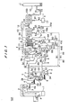
- FIG. 1 is a schematic diagram of a waste treatment apparatus 101 according to an embodiment of the present invention.
- the waste treatment apparatus 101 comprises a waste pit 1 for storing wastes a, a waste hopper 3 for storing wastes a temporarily, a crane 2 for conveying the wastes (a) from the waste pit 1 to the waste hopper 3, and a waste feeder 4 for feeding the wastes (a) discharged from the waste hopper 3 to a fluidized-bed gasification furnace 5.
- the waste treatment apparatus 101 comprises a fluidized-bed gasification furnace 5 for pyrolizing and gasifying the wastes (a) supplied at a constant rate by the waste feeder 4 at a low temperature to produce combustible gas m, an incombustible discharge apparatus 6 for discharging and classifying incombustibles d discharged from a bottom of the fluidized-bed gasification furnace 5 into small-sized incombustibles (c+d) containing silica sand c and large sized incombustibles d, and a vibrating screen 7 for vibrating and classifying the small-sized incombustibles (c+d) containing silica sand c into silica sand c and incombustibles d.
- a fluidized-bed gasification furnace 5 for pyrolizing and gasifying the wastes (a) supplied at a constant rate by the waste feeder 4 at a low temperature to produce combustible gas m
- the waste treatment apparatus 101 further comprises a swirling-type slagging combustion furnace 8 for combusting the produced gas m and melting solid components in the produced gas m.
- the swirling-type slagging combustion furnace 8 serves as a slagging combustion furnace.
- the waste feeder 4 comprises two-stage screw feeders 4a and 4b.
- the swirling-type slagging combustion furnace 8 has a circular shape in a horizontal cross section as shown in FIG. 2B and comprises a primary combustion chamber 8a, a secondary combustion chamber 8b, a slag separation section 8c, and a tertiary combustion chamber 8d.
- the waste treatment apparatus 101 comprises a slag conveyer 9 for conveying slag e discharged from a bottom of the swirling-type slagging combustion furnace 8, and a waste heat boiler 10 disposed immediately downstream of the swirling-type slagging combustion furnace 8 for recovering thermal energy from exhaust gas j discharged from the swirling-type slagging combustion furnace 8 and heating water f supplied thereto to generate steam g.
- the waste treatment apparatus 101 comprises an air preheater 11 for preheating combustion air b1 to be supplied to the fluidized-bed gasification furnace 5 and the swirling-type slagging combustion furnace 8, an economizer 12 for preheating water f to be supplied to the waste heat boiler 10, and a first bag filter 13a serving as a first filter (first ash separator/first ash collector) for filtrating the exhaust gas j discharged from the economizer 12 to collect fly ash h1 containing basic ash and heavy metal ash.
- the fly ash h1 collected by the first bag filter 13a is accumulated in an ash accumulator 18a, and then returned to the swirling-type slagging combustion furnace 8.
- the ash accumulator 18a comprises an ash storage tank (not shown), and an ash discharge device (not shown) disposed below the ash storage tank for discharging ash dropped from the ash storage tank.
- the ash discharge device is connected to a blower 41a serving as a first conveying device for feeding carrier air b2 to the ash discharge device, and the carrier air b2 fed from the blower 41a to the ash discharge device conveys the fly ash h1 discharged from the ash discharge device to the swirling-type slagging combustion furnace 8 by pneumatic transportation.
- the amount of the fly ash h1 conveyed to the swirling-type slagging combustion furnace 8 can be adjusted. A part of the fly ash h1 which is not returned to the swirling-type slagging combustion furnace 8 is discharged to the outside of the ash storage tank.
- a second bag filter 13b serving as a second filter (second ash separator/second ash collector) is disposed at a subsequent stage of the first bag filter 13a, and an injection nozzle 14 serving as an injection device for injecting slaked lime i as a neutralizer is provided on a pipe which connects the first bag filter 13a and the second bag filter 13b.
- the slaked lime i is mixed into the exhaust gas j at the location immediately upstream of the second bag filter 13b to thus neutralize the exhaust gas j.
- the neutralized ash h2 contained in the exhaust gas j is collected by the second bag filter 13b.
- the waste treatment apparatus 101 further comprises an induced draft fan 19 for inducing the exhaust gas j from the second bag filter 13b, a stack 15 for discharging the exhaust gas j to the atmosphere, a steam turbine 16 which is driven by steam g produced in the waste heat boiler 10, and an ash treatment device 17 serving as a recovery device for treating the neutralized ash h2 to form treated ash k.
- Fly ash h1 is collected also by the waste heat boiler 10, the air preheater 11, and the economizer 12 due to reduction of flow velocity of the exhaust gas j.
- the fly ash h1 collected by the waste heat boiler 10 is accumulated in an ash accumulator 18b, and the fly ash h1 collected by the air preheater 11 and the economizer 12 is gathered, and then accumulated in an ash accumulator 18c.
- the fly ash h1 accumulated in the ash accumulators 18b and 18c is partly or wholly discharged from the ash accumulators 18b and 18c and joined together, and then returned to the swirling-type slagging combustion furnace 8.
- the ash accumulators 18b and 18c can discharge a part of the fly ash h1 to the outside.
- the ash accumulators 18b and 18c comprise ash storage tanks (not shown), and ash discharge devices (not shown) disposed below the ash storage tanks for discharging ash dropped from the ash storage tanks, respectively.
- the ash discharge devices are connected to blowers 41b and 41c, respectively, for feeding carrier air b2 to the respective ash discharge devices, and the carrier air b2 fed from the blowers 41b and 41c to the respective ash discharge devices conveys the fly ash h1 discharged from the ash discharge devices to the swirling-type slagging combustion furnace 8 by pneumatic transportation.
- the amount of the fly ash h1 conveyed to the swirling-type slagging combustion furnace 8 can be adjusted. A part of the fly ash h1 which is not returned to the swirling-type slagging combustion furnace 8 is discharged to the outside of the respective ash storage tanks.
- the blower 41b serves as a second conveying device.
- the blower 41c serves as a third conveying device and also a fourth conveying device.
- Wastes (a) carried in by a truck are stored in the waste pit 1, and then the wastes a are supplied to the waste hopper 3 by the crane 2.
- the wastes (a) are withdrawn at a constant rate by the waste feeder 4 (two-stage screw feeders 4a and 4b) provided below the waste hopper 3, and supplied to the fluidized-bed gasification furnace 5.
- the combustion air b1 is supplied to the bottom of the fluidized-bed gasification furnace 5 to form a fluidized bed of silica sand c over a diffuser plate 5a formed in the fluidized-bed gasification furnace 5.
- the wastes (a) are supplied into the fluidized-bed gasification furnace 5, and dropped into the fluidized bed of silica sand c which is kept at a low temperature of 450 to 650°C.
- the wastes (a) are brought into contact with the heated silica sand c and the combustion air b1, and pyrolyzed and gasified rapidly, thus producing combustible gas, tar and fixed carbon.
- the fixed carbon is pulverized by a vigorous stirring motion in the fluidized bed. Further, the combustion air b1 is supplied also to a freeboard 5b formed in the upper portion of the fluidized-bed gasification furnace 5 for thereby gasifying tar and fixed carbon at a high temperature of 650 to 850°C.
- the silica sand c and the incombustibles d are discharged from the bottom of the fluidized-bed gasification furnace 5 by the incombustible discharge apparatus 6, and then classified.
- the incombustibles d contain metals such as iron, steel, copper, and aluminum. Since the interior of the fluidized-bed gasification furnace 5 is in a reducing atmosphere, metals can be recovered in a non-oxidized, and clean condition.
- the secondary combustion caused by blowing of the combustion air b1 in the freeboard 5b is not essential in the present invention.
- the reason for performing the secondary combustion is to improve controllability of the fluidized-bed furnace, and prevent the temperature in the slagging combustion furnace from rising excessively in the case where combustible gas introduced from the fluidized-bed furnace into the slagging combustion furnace has a high calorific value.
- the secondary combustion in the freeboard is not essential.
- the fluidized-bed furnace it is particularly desirable to form a revolving flow of a fluidized medium such as silica sand. This is because a slow gasification of wastes can be performed by the revolving flow of the fluidized medium to suppress fluctuation of produced gas in quality and quantity which is to be introduced into the slagging combustion furnace.
- the fluidized-bed furnace may comprise an internal circulating fluidized-bed furnace or an external circulating fluidized-bed furnace.
- a kiln furnace can be used other than the fluidized-bed furnace described in the present embodiment.
- the produced gas m accompanied by fine fixed carbon and discharged from the fluidized-bed gasification furnace 5 comprises combustible gas. Since the atmosphere contains no oxygen up to the inlet port or inlet of the swirling-type slagging combustion furnace 8, the produced gas m is unburned gas. In the swirling-type slagging combustion furnace 8, the produced gas m and the fixed carbon are mixed with the preheated combustion air b1 in a swirling flow created in the primary combustion chamber 8a, and combusted rapidly at a high temperature of 1200 to 1500°C. The combustion is completed in the inclined secondary chamber 8b.
- Ash content in the fixed carbon is entirely converted due to a high temperature into slag mist which is mostly trapped by molten slag phase on an inner wall of the primary combustion chamber 8a under a centrifugal force of the swirling flow.
- the trapped molten slag then flows down on the inner wall of the primary combustion chamber 8a and enters the secondary combustion chamber 8b, and is then discharged from the bottom of the slag separation section 8c.
- the slag e discharged from the bottom of the slag separation section 8c is conveyed by the slag conveyer 9. Unburned combustibles remaining in the gas are completely combusted in the tertiary combustion chamber 8d by the combustion air b1 supplied into the tertiary combustion chamber 8d.
- the exhaust gas j discharged from the waste heat boiler 10 is led to the waste heat boiler 10, and a high-temperature and high-pressure steam g generated in the waste heat boiler 10 is supplied to the steam turbine 16 coupled to a generator to generate electric power.
- the exhaust gas j discharged from the waste heat boiler 10 preheats the combustion air b1 in the air preheater 11, and condense water f supplied from the steam turbine 16 in the economizer 12, and thus the temperature of the exhaust gas j is lowered.
- the exhaust gas j from which fly ash h1 containing basic ash and heavy metal ash is removed by the first bag filter 13a is neutralized by mixing powdery slaked lime i as dechlorination agent.
- the exhaust gas j passes through the second bag filter 13b by which neutralized ash h2 is removed, and passes through the induced draft fan 19, and is then discharged from the stack 15 to the atmosphere.
- the slaked lime i reacts mainly with hydrogen chloride contained in the exhaust gas j to produce calcium chloride. Normally, the slaked lime i is added to the exhaust gas j by 1.5 to 2.5 equivalent to hydrogen chloride contained in the exhaust gas j.
- Neutralized ash h2 containing calcium chloride is treated in the ash treatment device 17 to form treated ash k.
- the amount of fly ash h1 returned to the swirling-type slagging combustion furnace 8 can be adjusted.
- the collected fly ash h1 is partly or wholly returned to the swirling-type slagging combustion furnace 8.
- the exhaust gas j After removing the fly ash h1 from the exhaust gas j in the first bag filter 13a, the exhaust gas j is neutralized before the exhaust gas j enters the second bag filter 13b. Therefore, the amount of slaked lime i to be used can be smaller, compared with the case in which the exhaust gas j is neutralized before the exhaust gas j enters the first bag filter 13a.
- the fly ash h1 collected by the first bag filter 13a and containing basic agent and heavy metal ash is accumulated in the ash accumulator 18a, the accumulated fly ash h1 is partly or wholly conveyed with pneumatic transportation to the swirling-type slagging combustion furnace 8 by the carrier air b2, and then melted in the swirling-type slagging combustion furnace 8 to produce slag. Therefore, the percentage of slagging ([slag weight/(slag weight + fly ash weight)] ⁇ 100(%)) is further increased.
- the fly ash h1 collected by the waste heat boiler 10 and the economizer 12 and accumulated in the ash accumulators 18b and 18c is partly or wholly conveyed with pneumatic transportation to the swirling-type slagging combustion furnace 8 by the carrier air b2, and then melted in the swirling-type slagging combustion furnace 8 to produce slag. Therefore, the percentage of slagging is further increased.
- the percentage of slagging is in the range of 70 to 80 %. In the present embodiment, the percentage of slagging can be increased to 90 % or more.
- fly ash h1 is returned indirectly to the swirling-type slagging combustion furnace via the gasification furnace such that the fly ash h1 is introduced into the fluidized-bed gasification furnace 5 together with the wastes a using the waste feeder 4 of the fluidized-bed gasification furnace 5, or the fly ash h1 is introduced into the fluidized-bed gasification furnace 5 together with sand using the sand circulating system of the fluidized-bed gasification furnace 5.
- the fly ash h1 may be returned to the duct which connects the gasification furnace and the slagging combustion furnace.
- combustion air nozzles 21 are mounted on the upper portion of the primary combustion chamber 8a of the swirling-type slagging combustion furnace 8 at angularly equal intervals in an outer circumferential direction of the primary combustion chamber 8a.
- the combustion air nozzles 21 are disposed horizontally, and serve to introduce the combustion air b1 in a direction along an inner circumferential surface 8e having a circular shape in a horizontal cross section of the primary combustion chamber 8a so that the combustion air b1 introduced into the primary combustion chamber 8a creates a swirling flow in a counterclockwise direction in FIG. 2B.
- An inlet duct 20 for introducing the produced gas m supplied from the fluidized-bed gasification furnace 5 into the primary combustion chamber 8a is mounted on the swirling-type slagging combustion furnace 8.
- the inlet duct 20 is arranged such that the produced gas m is introduced into the primary combustion chamber 8a in a direction along the inner circumferential surface 8e of the primary combustion chamber 8a so as to create a swirling flow in a counterclockwise direction in FIG. 2B.
- Three nozzles are mounted vertically in line on the primary combustion chamber 8a at the location where the inlet duct 20 is attached to the primary combustion chamber 8a. These three nozzles are arranged so as to introduce return ash into the slagging combustion furnace horizontally.
- the uppermost nozzle serves as a return ash nozzle 22 for introducing the collected fly ash h1 discharged from the waste heat boiler 10, the air preheater 11 and the economizer 12 into the primary combustion chamber 8a.
- the return ash nozzle 22 constitutes an introduction device.
- the intermediate nozzle serves as a return ash nozzle 23 for introducing the collected fly ash h1 discharged from the first bag filter 13a into the primary combustion chamber 8a.
- the return ash nozzle 23 also constitutes an introduction device.
- the lowermost nozzle serves as a combustion air nozzle 24 for introducing the combustion air b1 into the primary combustion chamber 8a.
- the fly ash h1 collected in the air preheater 11 may be accumulated, joined to the fly ash h1 collected by the waste heat boiler 10, and then returned to the swirling-type slagging combustion furnace 8 through the return ash nozzle 22.
- the above three nozzles introduce the fly ash h1 and the combustion air b1 into the primary combustion chamber 8a in a direction along the inner circumferential surface 8e of the swirling-type slagging combustion furnace 8 and along the flow of the produced gas m such that the fly ash h1 and the combustion air b1 create and support a swirling flow in a counterclockwise direction in FIG. 2B.
- Either of the collected fly ash h1 discharged from the economizer 12 and the collected fly as h1 discharged from the waste hear boiler 10 may be returned to the primary combustion chamber 8a, and the other may not be returned to the primary combustion chamber 8a.
- the return ash nozzles 22 and 23 are attached to the primary combustion chamber 8a at the location where the inlet duct 20 for introducing the produced gas m is attached to the primary combustion chamber 8a, and are attached at the location near the combustion air nozzle 24 in the same direction as the combustion air nozzle 24. Therefore, the produced gas m is combusted at the location where the produced gas m is introduced from the inlet duct 20 into the interior of the primary combustion chamber 8a, namely the introduction port of the produced gas m from the gasification furnace in the combustion chamber of the slagging combustion furnace, thus generating a flame and achieving high-temperature combustion.
- the collected fly ash h1 is introduced into the swirling-type slagging combustion furnace 8 such that the collected fly ash h1 is entrained by the flow of the produced gas m, the fly ash h1 can be led to the combustion area of the produced gas m, and efficiently melted.
- the collected fly ash h1 is returned to the primary combustion chamber 8a, and efficiently melted, and hence the percentage of slagging can be further increased. Further, because the fly ash h1 is supplied into the swirling-type slagging combustion furnace 8 in such a manner that the fly ash h1 is entrained by the combustion air b1, and the produced gas m reacts with the combustion air b1 to form a high-temperature flame immediately, the fly ash h1 is supplied directly into the formed high-temperature flame in a dense state.
- the flow velocity of the return ash is preferably 20 m/s at the outlets of the return ash nozzles 22 and 23. In this method, it is desirable to use carrier air for the fly ash h1 as combustion air.
- the return ash nozzles 22 and 23 are mounted on the upper half (upper half at the side of the inlet duct 20) of the primary combustion chamber 8a of the swirling-type slagging combustion furnace 8.
- the proper amount of air is supplied so that the produced gas m introduced into the swirling-type slagging combustion furnace 8 is combusted in the area of the upper half of the primary combustion chamber 8a
- the return ash nozzles 22 and 23 are mounted on the lower half of the primary combustion chamber 8a, the area near the return ash nozzles 22 and 23 is cooled by carrier air, and hence the fly ash h1 is liable not to be melted.
- the intermediate nozzle should serve as a return ash nozzle for introducing the fly ash h1 discharged from the first bag filter 13a, and the uppermost and lowermost nozzles should serve as a combustion air nozzle for introducing the combustion air b1.
- the counterclockwise swirling flow is formed in the swirling-type slagging combustion furnace as shown in FIG. 2B.
- the inlet duct, the combustion air nozzle, and the return ash nozzle may be arranged so as to form a clockwise swirling flow in FIG. 2B, and this arrangement is also effective in the same manner as the above embodiment.
- an ash pulverizer for pulverizing ash may be provided in the line 60 at the location between the waste heat boiler and the ash accumulator 18b, or the location between the junction of the fly ash h1 discharged from the air preheater 11 and the fly ash h1 discharged from the economizer 12 and the ash accumulator 18c.
- the collected fly ash h1 has a large diameter, and hence by pulverizing the fly ash h1 finely, the fly ash h1 can be reliably returned to the swirling-type slagging combustion furnace 8 by pneumatic transportation without clogging.
- the gathered fly ash which is formed by three kinds of fly ash may be pulverized finely by a single ash pulverizer, the gathered and pulverized fly ash may be fed to a single ash discharge device of a single ash accumulator comprising an ash storage tank and the ash discharge device, and the gathered and pulverized fly ash discharged from the ash discharge device may be supplied with pneumatic transportation to the swirling-type slagging combustion furnace by a single blower.
- the fly ash h1 discharged from the waste heat boiler 10, the fly ash h1 discharged from the air preheater 11, and the fly ash h1 discharged from the economizer 12 may be separately returned to the swirling-type slagging combustion furnace 8.
- the amount of the fly ash h1 collected by the waste heat boiler 10 the amount of the fly ash h1 collected by the air preheater 11, the amount of the fly ash collected by the economizer 12, any one of them may be smaller than the other, the smaller amount of the fly ash h1 may be accumulated in the ash accumulator, and may be separately recovered, without being returned to the swirling-type slagging combustion furnace 8.
- the waste (a) may be treated by a treatment method comprising a first step for pyrolizing and gasifying the wastes (a) at a low temperature to produce gas m; a second step for combusting the gas m at a high temperature and melting solid components contained in the gas m; a third step for filtrating the exhaust gas j generated in the second step by the first filter 13a to collect fly ash h1 contained in the exhaust gas j; a fourth step for injecting a neutralizer i into the exhaust gas j discharged from the first filter 13a; a fifth step for filtrating the exhaust gas j into which the neutralizer i has been injected, by a second filter (second ash separator/second ash collector) 13b to collect neutralized ash h2 contained in the exhaust gas j; a sixth step for returning the fly ash h1 collected by the first filter 13a to the slagging combustion furnace 8; a seventh step performed prior to the third step for recovering energy of the exhaust gas j
- the waste a may be treated by a treating method comprising a ninth step performed prior to the third step for recovering energy of the exhaust gas j discharged from the waste heat boiler 10; and a tenth step for returning fly ash h1 collected by the economizer 12 to the slagging combustion furnace 8.
- the fly ash h1 collected by the first filter or the waste heat boiler or the economizer or the air preheater may be returned to the slagging combustion furnace 8 so as to be introduced into the primary combustion chamber 8a in the direction along the inner circumferential surface 8e of the primary combustion chamber 8a.
- the collected fly ash h1 may be returned to the area where the produced gas m which has not contacted the combustion air b1 and has not been combusted exists in the slagging combustion furnace 8.
- the exhaust gas is filtrated by the first filter
- the collected fly ash is returned to the slagging combustion furnace by conveying the collected fly ash with the first conveying device
- the neutralizer is injected into the exhaust gas discharged from the first filter by the injection device
- the exhaust gas into which the neutralizer has been injected is filtrated by the second filter to collect the neutralized ash
- the collected neutralized ash is recovered by the recovery device.
- the fly ash collected by the first filter is conveyed to the slagging combustion furnace, the percentage of slagging in the slagging combustion furnace can be increased by melting the fly ash in the slagging combustion furnace, and the collected fly ash which needs neutralization treatment can be reduced. Further, because the neutralizer is injected into the exhaust gas from which the fly ash has been removed by the first filter, the amount of the neutralizer to be used can be reduced.
- a gasification and slagging combustion treatment for treating wastes are described.
- the present invention is also applicable to a two-stage gasification apparatus comprising a fluidized-bed gasification furnace and a swirling-type slagging combustion gasification furnace.
- the fluidized-bed gasification furnace may employ the same type as the fluidized-bed gasification furnace described in the above embodiment.
- the swirling-type slagging combustion gasification furnace the combustible gas obtained by pyrolysis and gasification in the fluidized-bed gasification furnace is reformed at a high temperature of 1300°C or higher to produce gas composed mainly of H 2 , CO, and CO 2 , and fly ash is melted into slag.
- the percentage of slagging is required to be increased.
- ash contained in the produced gas discharged from the swirling-type slagging combustion gasification furnace is collected in the ash collector provided at the subsequent stage of the swirling-type slagging combustion gasification furnace, and the collected ash is returned to the slagging combustion gasification furnace and the fluidized-bed gasification furnace with pneumatic transportation by using inert gas, and thus increasing the percentage of slagging as with the above embodiment.
- nozzles are arranged so that a swirling flow of gas in a clockwise direction or a swirling flow of gas in a counterclockwise can be formed, and the collected ash is introduced into the respective nozzles, as with the above embodiment.
- the present invention is applicable to waste treatment apparatus and method for combusting and treating wastes such as municipal wastes, refuse-derived fuel (RDF), plastic wastes, waste FRP, biomass wastes, automobile wastes and waste oil.
- wastes such as municipal wastes, refuse-derived fuel (RDF), plastic wastes, waste FRP, biomass wastes, automobile wastes and waste oil.
Landscapes
- Engineering & Computer Science (AREA)
- Mechanical Engineering (AREA)
- General Engineering & Computer Science (AREA)
- Gasification And Melting Of Waste (AREA)
- Chimneys And Flues (AREA)
- Incineration Of Waste (AREA)
- Treating Waste Gases (AREA)
- Processing Of Solid Wastes (AREA)
Abstract
Description
- The present invention relates to waste treatment apparatus and method, and more particularly to waste treatment apparatus and method for combusting and treating wastes such as municipal wastes, refuse-derived fuel (RDF), plastic wastes, waste FRP, biomass wastes, automobile wastes and waste oil.
- The present invention also relates to two-stage gasification apparatus and method comprising a fluidized-bed gasification furnace and a swirling-type slagging combustion gasification furnace.
- As a waste treatment method, there has been known a method in which wastes are pyrolyzed and gasified at a low temperature in a gasification furnace to produce combustible gas, the produced combustible gas is supplied to a slagging combustion furnace, and then the produced combustion gas is combusted at a high temperature to melt solid components contained in the produced combustion gas and recover slag from a bottom of the slagging combustion furnace. Exhaust gas generated by combustion in the slagging combustion furnace is led to a waste heat boiler in which steam is generated by heat exchange with the exhaust gas for thereby recovering heat from the exhaust gas. The exhaust gas discharged from the waste heat boiler is led to a first bag filter in which ash contained in the exhaust gas is collected. The collected ash is treated by a slagging pyrolysis process, or is treated by a neutralization process using slaked lime, and is then discarded in a landfill site. The exhaust gas discharged from the first bag filter is neutralized by mixing slaked lime, and then the exhaust gas is led to a second bag filter in which neutralized ash is collected.
- According to the conventional waste treatment apparatus, there exists a large amount of collected ash which is not slagged, but is neutralized by a neutralizer and is discarded in the landfill site. In this case, if the percentage of slagging is further increased, the amount of neutralizer to be used can be decreased, and the collected ash to be discarded in the landfill site can be decreased. Therefore, there has been a demand for increasing the percentage of slagging, for the purpose of a reduction in costs and a prolonging of the life of the landfill site.
- The present invention has been made in view of the above drawbacks. It is therefore an object of the present invention to provide waste treatment apparatus and method which can increase the percentage of slagging, reduce the amount of the collected ash required to be neutralized, and reduce the amount of neutralizer to be used.
- In order to achieve the above object of the present invention, according to an aspect of the present invention, there is provided a waste treatment apparatus comprising: a gasification furnace for gasifying wastes to produce combustible gas; a slagging combustion furnace for combusting the combustible gas and melting solid components contained in the combustible gas to generate exhaust gas; a first filter for filtrating the exhaust gas discharged from the slagging combustion furnace and collecting fly ash contained in the exhaust gas; an injection device for injecting a neutralizer into the exhaust gas discharged from the first filter; a second filter for filtrating the exhaust gas into which the neutralizer has been injected, and collecting'neutralized ash contained in the exhaust gas; a recovery device for recovering the neutralized ash which has been collected; and a conveying device for conveying fly ash collected by the first filter to the slagging combustion furnace.
- According to the present invention, the
first filter 13a, thesecond filter 13b, theinjection device 14, the conveying decide 41a, and therecovery device 17 are provided. Thus, exhaust gas j is filtrated by thefirst filter 13a, and fly ash h1 collected by thefirst filter 13a is conveyed by theconveying device 41a and returned to the slagging combustion furnace 8, a neutralizer i is injected into the exhaust gas j discharged from thefirst filter 13a by theinjection device 14, the exhaust gas j into which the neutralizer i has been injected is filtrated by thesecond filter 13b to collect the neutralized ash h2, and the collected the neutralized ash h2 is recovered by therecovery device 17. - Therefore, the fly ash h1 collected by the
first filter 13a is conveyed to the slagging combustion furnace 8, and hence the fly ash h1 is melted in the slagging combustion furnace 8 to thus increase the percentage of slagging in the slagging combustion furnace 8, and the collected ash which requires neutralization treatment can be decreased. Further, after the fly ash h1 is collected in thefirst filter 13a, the neutralizer i is injected into the exhaust gas j, and hence the amount of the neutralizer i to be used can be decreased and the amount of neutralized ash h2 can be decreased. Further, because the fly ash h1 which does not contain the neutralized ash h2 is conveyed to the slagging combustion furnace 8, the fly ash h1 can be efficiently melted and treated. Further, since the exhaust gas j which does not contain components of the neutralizer i is discharged from the slagging combustion furnace 8, and the fly ash h1 collected by thefirst filter 13a does not contain components of the neutralizer i, slag e having a high quality can be produced. - According to a preferred aspect of the present invention, a waste treatment apparatus further comprises a waste heat boiler for recovering thermal energy of the exhaust gas discharged from the slagging combustion furnace, and a conveying device for conveying fly ash collected by the waste heat boiler to the slagging combustion furnace.
- With this arrangement, because the conveying device 41b is provided, the fly ash h1 collected by the
waste heat boiler 10 is conveyed to the slagging combustion furnace 8 by the conveying device 41b, and melted in the slagging combustion furnace 8, thus further increasing the percentage of slagging in the slagging combustion furnace 8. - According to a preferred aspect of the present invention, a waste treatment apparatus further comprises an economizer for preheating water to be fed to the waste heat boiler by thermal energy of the exhaust gas discharged from the waste heat boiler, and a conveying device for conveying fly ash collected by the economizer to the slagging combustion furnace.
- With this arrangement, because the
conveying device 41c is provided, the fly ash h1 collected by theeconomizer 12 is conveyed to the slagging combustion furnace 8 by theconveying device 41c, and melted in the slagging combustion furnace 8, thus further increasing the percentage of slagging in the slagging combustion furnace 8. - According to a preferred aspect of the present invention, a waste treatment apparatus further comprises an air preheater for preheating combustion air to be fed to the gasification furnace and the slagging combustion furnace by thermal energy of the exhaust gas discharged from the waste heat boiler, and a conveying device for conveying fly ash collected by the air preheater to the slagging combustion furnace.
- With this arrangement, because the
conveying device 41c is provided, the fly ash h1 collected by theair preheater 11 is conveyed to the slagging combustion furnace 8 by theconveying device 41c, and melted in the slagging combustion furnace 8, thus further increasing the percentage of slagging in the slagging combustion furnace 8. - According to a preferred aspect of the present invention, a waste treatment apparatus further comprises an introduction device for introducing the fly ash conveyed to the slagging combustion furnace into the slagging combustion furnace in a direction along an inner circumferential surface of the slagging combustion furnace.
- With this arrangement, because the
introduction devices circumferential surface 8e of the slagging combustion furnace to form a swirling flow in the slagging combustion furnace 8, and the fly ash h1 can be efficiently melted and the percentage of slagging in the slagging combustion furnace 8 can be further increased. - According to another aspect of the present invention, there is provided a waste treatment apparatus comprising: a gasification furnace for gasifying wastes to produce combustible gas; a slagging combustion furnace for combusting the combustible gas and melting solid components contained in the combustible gas to generate exhaust gas; a filter for filtrating the exhaust gas discharged from the slagging combustion furnace and collecting fly ash contained in the exhaust gas; a conveying device for conveying the fly ash collected by the filter to the slagging combustion furnace; and an introduction device for introducing the fly ash conveyed to the slagging combustion furnace into the slagging combustion furnace.
- According to the present invention, because the
filter 13a, theconveying device 41a and theintroduction device 23 are provided, exhaust gas j is filtrated by thefilter 13a, the collected fly ash h1 is conveyed to the slagging combustion furnace 8 by theconveying device 41a, the conveyed fly ash h1 can be introduced into the slagging combustion furnace 8 in a direction along the innercircumferential surface 8e of the slagging combustion furnace 8 by theintroduction device 23 to form a swirling flow in the slagging combustion furnace 8, and the fly ash h1 can be efficiently melted and the percentage of slagging in the slagging combustion furnace 8 can be further increase. - According to a preferred aspect of the present invention, the introduction device is mounted on the slagging combustion furnace at a location where the combustible gas which has not been combusted exists.
- With this arrangement, because the
introduction devices gasification furnace 5 exists and such combustible gas has not been combusted, the introduced fly ash h1 is conveyed by the flow of the combustible gas m to the flame formed by combustion in the slagging combustion furnace 8, and hence the fly ash h1 is exposed to the maximum temperature range. Therefore, the fly ash h1 can be efficiently melted. - According to a preferred aspect of the present invention, a waste treatment apparatus further comprises an inlet duct for introducing the combustible gas into the slagging combustion furnace, and the introduction device is mounted on the inlet duct.
- With this arrangement, the slagging combustion furnace 8 comprises the
inlet duct 20 for introducing the combustible gas m into the slagging combustion furnace 8 in a direction along the innercircumferential surface 8e of the slagging combustion furnace 8, and theintroduction devices inlet duct 20. Therefore, the conveyed fly ash h1 can be introduced by theintroduction devices circumferential surface 8e of the slagging combustion furnace 8 before the combustible gas m is combusted in the slagging combustion furnace 8. Thereafter, the combustible gas m introduced from theinlet duct 20 of the slagging combustion furnace 8 is combusted in the slagging combustion furnace 8 to generate flame, and hence the introduced fly ash h1 can pass through a high-temperature combustion range to thus melt the fly ash h1 efficiently. - According to another aspect of the present invention, there is provided a waste treatment method comprising: pyrolizing and gasifying wastes to produce combustible gas; combusting the combustible gas and melting solid components contained in the combustible gas to generate exhaust gas; filtrating the exhaust gas discharged from the slagging combustion furnace and collecting fly ash contained in the exhaust gas; injecting a neutralizer into the exhaust gas discharged from the first filter; filtrating the exhaust gas into which the neutralizer has been injected, by a second filter, and collecting neutralized ash contained in the exhaust gas; and returning the fly ash collected by the first filter to the slagging combustion furnace.
-
- FIG. 1 is a schematic diagram of a waste treatment apparatus according to an embodiment of the present invention;
- FIG. 2A is a front view of a swirling-type slagging combustion furnace, the view showing an arrangement of nozzles for return ash; and
- FIG. 2B is a fragmentary plan view of the swirling-type slagging combustion furnace.
-
- A waste treatment apparatus according to an embodiment of the present invention will be described below with reference to the drawings. In FIGS. 1, 2A and 2B, like or corresponding parts are denoted by like or corresponding reference numerals throughout views, and repetitive description is eliminated.
- FIG. 1 is a schematic diagram of a
waste treatment apparatus 101 according to an embodiment of the present invention. Thewaste treatment apparatus 101 comprises awaste pit 1 for storing wastes a, a waste hopper 3 for storing wastes a temporarily, acrane 2 for conveying the wastes (a) from thewaste pit 1 to thewaste hopper 3, and a waste feeder 4 for feeding the wastes (a) discharged from thewaste hopper 3 to a fluidized-bed gasification furnace 5. - The
waste treatment apparatus 101 comprises a fluidized-bed gasification furnace 5 for pyrolizing and gasifying the wastes (a) supplied at a constant rate by the waste feeder 4 at a low temperature to produce combustible gas m, an incombustible discharge apparatus 6 for discharging and classifying incombustibles d discharged from a bottom of the fluidized-bed gasification furnace 5 into small-sized incombustibles (c+d) containing silica sand c and large sized incombustibles d, and a vibratingscreen 7 for vibrating and classifying the small-sized incombustibles (c+d) containing silica sand c into silica sand c and incombustibles d. Thewaste treatment apparatus 101 further comprises a swirling-type slagging combustion furnace 8 for combusting the produced gas m and melting solid components in the produced gas m. The swirling-type slagging combustion furnace 8 serves as a slagging combustion furnace. The waste feeder 4 comprises two-stage screw feeders primary combustion chamber 8a, asecondary combustion chamber 8b, aslag separation section 8c, and atertiary combustion chamber 8d. - Further, the
waste treatment apparatus 101 comprises aslag conveyer 9 for conveying slag e discharged from a bottom of the swirling-type slagging combustion furnace 8, and awaste heat boiler 10 disposed immediately downstream of the swirling-type slagging combustion furnace 8 for recovering thermal energy from exhaust gas j discharged from the swirling-type slagging combustion furnace 8 and heating water f supplied thereto to generate steam g. - Further, the
waste treatment apparatus 101 comprises anair preheater 11 for preheating combustion air b1 to be supplied to the fluidized-bed gasification furnace 5 and the swirling-type slagging combustion furnace 8, aneconomizer 12 for preheating water f to be supplied to thewaste heat boiler 10, and afirst bag filter 13a serving as a first filter (first ash separator/first ash collector) for filtrating the exhaust gas j discharged from theeconomizer 12 to collect fly ash h1 containing basic ash and heavy metal ash. The fly ash h1 collected by thefirst bag filter 13a is accumulated in anash accumulator 18a, and then returned to the swirling-type slagging combustion furnace 8. - The
ash accumulator 18a comprises an ash storage tank (not shown), and an ash discharge device (not shown) disposed below the ash storage tank for discharging ash dropped from the ash storage tank. The ash discharge device is connected to ablower 41a serving as a first conveying device for feeding carrier air b2 to the ash discharge device, and the carrier air b2 fed from theblower 41a to the ash discharge device conveys the fly ash h1 discharged from the ash discharge device to the swirling-type slagging combustion furnace 8 by pneumatic transportation. By adjusting the amount of ash discharged from the ash discharge device, the amount of the fly ash h1 conveyed to the swirling-type slagging combustion furnace 8 can be adjusted. A part of the fly ash h1 which is not returned to the swirling-type slagging combustion furnace 8 is discharged to the outside of the ash storage tank. - A
second bag filter 13b serving as a second filter (second ash separator/second ash collector) is disposed at a subsequent stage of thefirst bag filter 13a, and aninjection nozzle 14 serving as an injection device for injecting slaked lime i as a neutralizer is provided on a pipe which connects thefirst bag filter 13a and thesecond bag filter 13b. The slaked lime i is mixed into the exhaust gas j at the location immediately upstream of thesecond bag filter 13b to thus neutralize the exhaust gas j. The neutralized ash h2 contained in the exhaust gas j is collected by thesecond bag filter 13b. - The
waste treatment apparatus 101 further comprises an induceddraft fan 19 for inducing the exhaust gas j from thesecond bag filter 13b, astack 15 for discharging the exhaust gas j to the atmosphere, asteam turbine 16 which is driven by steam g produced in thewaste heat boiler 10, and anash treatment device 17 serving as a recovery device for treating the neutralized ash h2 to form treated ash k. - Fly ash h1 is collected also by the
waste heat boiler 10, theair preheater 11, and theeconomizer 12 due to reduction of flow velocity of the exhaust gas j. The fly ash h1 collected by thewaste heat boiler 10 is accumulated in anash accumulator 18b, and the fly ash h1 collected by theair preheater 11 and theeconomizer 12 is gathered, and then accumulated in an ash accumulator 18c. The fly ash h1 accumulated in theash accumulators 18b and 18c is partly or wholly discharged from theash accumulators 18b and 18c and joined together, and then returned to the swirling-type slagging combustion furnace 8. Theash accumulators 18b and 18c can discharge a part of the fly ash h1 to the outside. - The
ash accumulators 18b and 18c comprise ash storage tanks (not shown), and ash discharge devices (not shown) disposed below the ash storage tanks for discharging ash dropped from the ash storage tanks, respectively. The ash discharge devices are connected toblowers 41b and 41c, respectively, for feeding carrier air b2 to the respective ash discharge devices, and the carrier air b2 fed from theblowers 41b and 41c to the respective ash discharge devices conveys the fly ash h1 discharged from the ash discharge devices to the swirling-type slagging combustion furnace 8 by pneumatic transportation. By adjusting the amount of ash discharged from the respective ash discharge devices, the amount of the fly ash h1 conveyed to the swirling-type slagging combustion furnace 8 can be adjusted. A part of the fly ash h1 which is not returned to the swirling-type slagging combustion furnace 8 is discharged to the outside of the respective ash storage tanks. The blower 41b serves as a second conveying device. Theblower 41c serves as a third conveying device and also a fourth conveying device. - The combustion air b1 supplied to the
air preheater 11, the combustion air b1 discharged from the air preheater and supplied to the fluidized-bed gasification furnace and the swirling-type slagging combustion furnace 8, silica sand c, incombustibles d discharged from the incombustible discharge apparatus 6, incombustibles d discharged from the vibratingscreen 7, slag e, water f, steam g, collected fly ash h1 discharged from thefirst bag filter 13a and theeconomizer 12, collected fly ash h1 discharged from thewaste heat boiler 10, neutralized ash h2, slaked lime i, carrier air b2 of the collected fly ash h1 discharged from thefirst bag filter 13a, carrier air b2 of the collected fly ash h1 discharged from theeconomizer 12, carrier air b2 of the collected fly ash h1 discharged from thewaste heat boiler 10 are supplied throughrespective supply lines 51 to 65. - Next, operation of the
waste treatment apparatus 101 according to the embodiment of the present invention will be described below. Wastes (a) carried in by a truck (not shown) are stored in thewaste pit 1, and then the wastes a are supplied to thewaste hopper 3 by thecrane 2. The wastes (a) are withdrawn at a constant rate by the waste feeder 4 (two-stage screw feeders waste hopper 3, and supplied to the fluidized-bed gasification furnace 5. - The combustion air b1 is supplied to the bottom of the fluidized-
bed gasification furnace 5 to form a fluidized bed of silica sand c over adiffuser plate 5a formed in the fluidized-bed gasification furnace 5. The wastes (a) are supplied into the fluidized-bed gasification furnace 5, and dropped into the fluidized bed of silica sand c which is kept at a low temperature of 450 to 650°C. Thus, the wastes (a) are brought into contact with the heated silica sand c and the combustion air b1, and pyrolyzed and gasified rapidly, thus producing combustible gas, tar and fixed carbon. - The fixed carbon is pulverized by a vigorous stirring motion in the fluidized bed. Further, the combustion air b1 is supplied also to a
freeboard 5b formed in the upper portion of the fluidized-bed gasification furnace 5 for thereby gasifying tar and fixed carbon at a high temperature of 650 to 850°C. The silica sand c and the incombustibles d are discharged from the bottom of the fluidized-bed gasification furnace 5 by the incombustible discharge apparatus 6, and then classified. The incombustibles d contain metals such as iron, steel, copper, and aluminum. Since the interior of the fluidized-bed gasification furnace 5 is in a reducing atmosphere, metals can be recovered in a non-oxidized, and clean condition. - However, the secondary combustion caused by blowing of the combustion air b1 in the
freeboard 5b is not essential in the present invention. The reason for performing the secondary combustion is to improve controllability of the fluidized-bed furnace, and prevent the temperature in the slagging combustion furnace from rising excessively in the case where combustible gas introduced from the fluidized-bed furnace into the slagging combustion furnace has a high calorific value. However, in the case where only combustible gas having a low calorific value is obtained, the secondary combustion in the freeboard is not essential. - Further, in the fluidized-bed gasification furnace, it is particularly desirable to form a revolving flow of a fluidized medium such as silica sand. This is because a slow gasification of wastes can be performed by the revolving flow of the fluidized medium to suppress fluctuation of produced gas in quality and quantity which is to be introduced into the slagging combustion furnace. In the present embodiment, the fluidized-bed furnace may comprise an internal circulating fluidized-bed furnace or an external circulating fluidized-bed furnace. Further, if the fluctuation of produced gas in quality and quantity which is to be introduced into the subsequent slagging combustion furnace can be suppressed, as a gasification furnace, a kiln furnace can be used other than the fluidized-bed furnace described in the present embodiment.
- The produced gas m accompanied by fine fixed carbon and discharged from the fluidized-
bed gasification furnace 5 comprises combustible gas. Since the atmosphere contains no oxygen up to the inlet port or inlet of the swirling-type slagging combustion furnace 8, the produced gas m is unburned gas. In the swirling-type slagging combustion furnace 8, the produced gas m and the fixed carbon are mixed with the preheated combustion air b1 in a swirling flow created in theprimary combustion chamber 8a, and combusted rapidly at a high temperature of 1200 to 1500°C. The combustion is completed in the inclinedsecondary chamber 8b. - Ash content in the fixed carbon is entirely converted due to a high temperature into slag mist which is mostly trapped by molten slag phase on an inner wall of the
primary combustion chamber 8a under a centrifugal force of the swirling flow. The trapped molten slag then flows down on the inner wall of theprimary combustion chamber 8a and enters thesecondary combustion chamber 8b, and is then discharged from the bottom of theslag separation section 8c. The slag e discharged from the bottom of theslag separation section 8c is conveyed by theslag conveyer 9. Unburned combustibles remaining in the gas are completely combusted in thetertiary combustion chamber 8d by the combustion air b1 supplied into thetertiary combustion chamber 8d. - The exhaust gas j discharged from the
waste heat boiler 10 is led to thewaste heat boiler 10, and a high-temperature and high-pressure steam g generated in thewaste heat boiler 10 is supplied to thesteam turbine 16 coupled to a generator to generate electric power. The exhaust gas j discharged from thewaste heat boiler 10 preheats the combustion air b1 in theair preheater 11, and condense water f supplied from thesteam turbine 16 in theeconomizer 12, and thus the temperature of the exhaust gas j is lowered. Then, the exhaust gas j from which fly ash h1 containing basic ash and heavy metal ash is removed by thefirst bag filter 13a, is neutralized by mixing powdery slaked lime i as dechlorination agent. Thereafter, the exhaust gas j passes through thesecond bag filter 13b by which neutralized ash h2 is removed, and passes through the induceddraft fan 19, and is then discharged from thestack 15 to the atmosphere. - The slaked lime i reacts mainly with hydrogen chloride contained in the exhaust gas j to produce calcium chloride. Normally, the slaked lime i is added to the exhaust gas j by 1.5 to 2.5 equivalent to hydrogen chloride contained in the exhaust gas j. Neutralized ash h2 containing calcium chloride is treated in the
ash treatment device 17 to form treated ash k. The amount of fly ash h1 returned to the swirling-type slagging combustion furnace 8 can be adjusted. The collected fly ash h1 is partly or wholly returned to the swirling-type slagging combustion furnace 8. After removing the fly ash h1 from the exhaust gas j in thefirst bag filter 13a, the exhaust gas j is neutralized before the exhaust gas j enters thesecond bag filter 13b. Therefore, the amount of slaked lime i to be used can be smaller, compared with the case in which the exhaust gas j is neutralized before the exhaust gas j enters thefirst bag filter 13a. - The fly ash h1 collected by the
first bag filter 13a and containing basic agent and heavy metal ash is accumulated in theash accumulator 18a, the accumulated fly ash h1 is partly or wholly conveyed with pneumatic transportation to the swirling-type slagging combustion furnace 8 by the carrier air b2, and then melted in the swirling-type slagging combustion furnace 8 to produce slag. Therefore, the percentage of slagging ([slag weight/(slag weight + fly ash weight)] × 100(%)) is further increased. Further, the fly ash h1 collected by thewaste heat boiler 10 and theeconomizer 12 and accumulated in theash accumulators 18b and 18c is partly or wholly conveyed with pneumatic transportation to the swirling-type slagging combustion furnace 8 by the carrier air b2, and then melted in the swirling-type slagging combustion furnace 8 to produce slag. Therefore, the percentage of slagging is further increased. When the collected fly ash h1 is not returned to the swirling-type slagging combustion furnace 8, the percentage of slagging is in the range of 70 to 80 %. In the present embodiment, the percentage of slagging can be increased to 90 % or more. - In addition to the method in which the fly ash h1 is directly returned to the swirling-type slagging combustion furnace, there is a method in which the fly ash h1 is returned indirectly to the swirling-type slagging combustion furnace via the gasification furnace such that the fly ash h1 is introduced into the fluidized-
bed gasification furnace 5 together with the wastes a using the waste feeder 4 of the fluidized-bed gasification furnace 5, or the fly ash h1 is introduced into the fluidized-bed gasification furnace 5 together with sand using the sand circulating system of the fluidized-bed gasification furnace 5. The fly ash h1 may be returned to the duct which connects the gasification furnace and the slagging combustion furnace. - Next, arrangement of nozzles mounted on the swirling-type slagging combustion furnace 8 for returning the collected fly ash h1 collected by the
first bag filter 13a, theeconomizer 12, and thewaste heat boiler 10 to the swirling-type slagging combustion furnace 8 will be described below with reference to FIGS. 2A and 2B. - Four
combustion air nozzles 21 are mounted on the upper portion of theprimary combustion chamber 8a of the swirling-type slagging combustion furnace 8 at angularly equal intervals in an outer circumferential direction of theprimary combustion chamber 8a. Thecombustion air nozzles 21 are disposed horizontally, and serve to introduce the combustion air b1 in a direction along an innercircumferential surface 8e having a circular shape in a horizontal cross section of theprimary combustion chamber 8a so that the combustion air b1 introduced into theprimary combustion chamber 8a creates a swirling flow in a counterclockwise direction in FIG. 2B. Aninlet duct 20 for introducing the produced gas m supplied from the fluidized-bed gasification furnace 5 into theprimary combustion chamber 8a is mounted on the swirling-type slagging combustion furnace 8. Theinlet duct 20 is arranged such that the produced gas m is introduced into theprimary combustion chamber 8a in a direction along the innercircumferential surface 8e of theprimary combustion chamber 8a so as to create a swirling flow in a counterclockwise direction in FIG. 2B. - Three nozzles are mounted vertically in line on the
primary combustion chamber 8a at the location where theinlet duct 20 is attached to theprimary combustion chamber 8a. These three nozzles are arranged so as to introduce return ash into the slagging combustion furnace horizontally. The uppermost nozzle serves as areturn ash nozzle 22 for introducing the collected fly ash h1 discharged from thewaste heat boiler 10, theair preheater 11 and theeconomizer 12 into theprimary combustion chamber 8a. Thereturn ash nozzle 22 constitutes an introduction device. The intermediate nozzle serves as areturn ash nozzle 23 for introducing the collected fly ash h1 discharged from thefirst bag filter 13a into theprimary combustion chamber 8a. Thereturn ash nozzle 23 also constitutes an introduction device. Further, the lowermost nozzle serves as acombustion air nozzle 24 for introducing the combustion air b1 into theprimary combustion chamber 8a. - The fly ash h1 collected in the
air preheater 11 may be accumulated, joined to the fly ash h1 collected by thewaste heat boiler 10, and then returned to the swirling-type slagging combustion furnace 8 through thereturn ash nozzle 22. - The above three nozzles introduce the fly ash h1 and the combustion air b1 into the
primary combustion chamber 8a in a direction along the innercircumferential surface 8e of the swirling-type slagging combustion furnace 8 and along the flow of the produced gas m such that the fly ash h1 and the combustion air b1 create and support a swirling flow in a counterclockwise direction in FIG. 2B. Either of the collected fly ash h1 discharged from theeconomizer 12 and the collected fly as h1 discharged from the waste hearboiler 10 may be returned to theprimary combustion chamber 8a, and the other may not be returned to theprimary combustion chamber 8a. - The
return ash nozzles primary combustion chamber 8a at the location where theinlet duct 20 for introducing the produced gas m is attached to theprimary combustion chamber 8a, and are attached at the location near thecombustion air nozzle 24 in the same direction as thecombustion air nozzle 24. Therefore, the produced gas m is combusted at the location where the produced gas m is introduced from theinlet duct 20 into the interior of theprimary combustion chamber 8a, namely the introduction port of the produced gas m from the gasification furnace in the combustion chamber of the slagging combustion furnace, thus generating a flame and achieving high-temperature combustion. Further, because the collected fly ash h1 is introduced into the swirling-type slagging combustion furnace 8 such that the collected fly ash h1 is entrained by the flow of the produced gas m, the fly ash h1 can be led to the combustion area of the produced gas m, and efficiently melted. - In this manner, the collected fly ash h1 is returned to the
primary combustion chamber 8a, and efficiently melted, and hence the percentage of slagging can be further increased. Further, because the fly ash h1 is supplied into the swirling-type slagging combustion furnace 8 in such a manner that the fly ash h1 is entrained by the combustion air b1, and the produced gas m reacts with the combustion air b1 to form a high-temperature flame immediately, the fly ash h1 is supplied directly into the formed high-temperature flame in a dense state. Therefore, particles of the fly ash h1 are adhered to each other to make the size of the particles larger, and hence the fly ash h1 tends to be trapped on the inner wall surface of theprimary combustion chamber 8a and melted efficiently on the inner wall surface. The flow velocity of the return ash is preferably 20 m/s at the outlets of thereturn ash nozzles - It is desirable that the
return ash nozzles primary combustion chamber 8a of the swirling-type slagging combustion furnace 8. In general, because the proper amount of air is supplied so that the produced gas m introduced into the swirling-type slagging combustion furnace 8 is combusted in the area of the upper half of theprimary combustion chamber 8a, if thereturn ash nozzles primary combustion chamber 8a, the area near thereturn ash nozzles first bag filter 13a should be returned to theprimary combustion chamber 8a, and the fly ash h1 discharged from theeconomizer 12 and thewaste heat boiler 10 should not be returned to theprimary combustion chamber 8a. In this case, among the three nozzles attached to theprimary combustion chamber 8a at the location where the inlet duct is attached to theprimary combustion chamber 8a, the intermediate nozzle should serve as a return ash nozzle for introducing the fly ash h1 discharged from thefirst bag filter 13a, and the uppermost and lowermost nozzles should serve as a combustion air nozzle for introducing the combustion air b1. - In the above embodiment, the counterclockwise swirling flow is formed in the swirling-type slagging combustion furnace as shown in FIG. 2B. However, the inlet duct, the combustion air nozzle, and the return ash nozzle may be arranged so as to form a clockwise swirling flow in FIG. 2B, and this arrangement is also effective in the same manner as the above embodiment.
- Further, an ash pulverizer for pulverizing ash may be provided in the
line 60 at the location between the waste heat boiler and theash accumulator 18b, or the location between the junction of the fly ash h1 discharged from theair preheater 11 and the fly ash h1 discharged from theeconomizer 12 and the ash accumulator 18c. The collected fly ash h1 has a large diameter, and hence by pulverizing the fly ash h1 finely, the fly ash h1 can be reliably returned to the swirling-type slagging combustion furnace 8 by pneumatic transportation without clogging. - Further, it is desirable that after the fly ash discharged from the
air preheater 11 and the fly ash discharged from theeconomizer 12 are gathered, the fly ash discharged from thewaste heat boiler 10 is also gathered. The gathered fly ash which is formed by three kinds of fly ash may be pulverized finely by a single ash pulverizer, the gathered and pulverized fly ash may be fed to a single ash discharge device of a single ash accumulator comprising an ash storage tank and the ash discharge device, and the gathered and pulverized fly ash discharged from the ash discharge device may be supplied with pneumatic transportation to the swirling-type slagging combustion furnace by a single blower. - The fly ash h1 discharged from the
waste heat boiler 10, the fly ash h1 discharged from theair preheater 11, and the fly ash h1 discharged from theeconomizer 12 may be separately returned to the swirling-type slagging combustion furnace 8. Among the amount of the fly ash h1 collected by thewaste heat boiler 10, the amount of the fly ash h1 collected by theair preheater 11, the amount of the fly ash collected by theeconomizer 12, any one of them may be smaller than the other, the smaller amount of the fly ash h1 may be accumulated in the ash accumulator, and may be separately recovered, without being returned to the swirling-type slagging combustion furnace 8. - As shown in FIG. 1, the waste (a) may be treated by a treatment method comprising a first step for pyrolizing and gasifying the wastes (a) at a low temperature to produce gas m; a second step for combusting the gas m at a high temperature and melting solid components contained in the gas m; a third step for filtrating the exhaust gas j generated in the second step by the
first filter 13a to collect fly ash h1 contained in the exhaust gas j; a fourth step for injecting a neutralizer i into the exhaust gas j discharged from thefirst filter 13a; a fifth step for filtrating the exhaust gas j into which the neutralizer i has been injected, by a second filter (second ash separator/second ash collector) 13b to collect neutralized ash h2 contained in the exhaust gas j; a sixth step for returning the fly ash h1 collected by thefirst filter 13a to the slagging combustion furnace 8; a seventh step performed prior to the third step for recovering energy of the exhaust gas j discharged from the slagging combustion furnace 8 by thewaste heat boiler 10; and an eighth step for returning fly ash h1 collected by thewaste heat boiler 10 to the slagging combustion furnace 8. - Further, the waste a may be treated by a treating method comprising a ninth step performed prior to the third step for recovering energy of the exhaust gas j discharged from the
waste heat boiler 10; and a tenth step for returning fly ash h1 collected by theeconomizer 12 to the slagging combustion furnace 8. - For example, as shown in FIGS. 1 and 2, in the sixth step, the fly ash h1 collected by the first filter or the waste heat boiler or the economizer or the air preheater may be returned to the slagging combustion furnace 8 so as to be introduced into the
primary combustion chamber 8a in the direction along the innercircumferential surface 8e of theprimary combustion chamber 8a. - For example, as shown in FIGS. 1, 2A and 2B, in the sixth step, the collected fly ash h1 may be returned to the area where the produced gas m which has not contacted the combustion air b1 and has not been combusted exists in the slagging combustion furnace 8.
- As described above, according to the present invention, because the first filter, the second filter, the injection device, the first conveying device, and the recovery device are provided, the exhaust gas is filtrated by the first filter, the collected fly ash is returned to the slagging combustion furnace by conveying the collected fly ash with the first conveying device, the neutralizer is injected into the exhaust gas discharged from the first filter by the injection device, the exhaust gas into which the neutralizer has been injected is filtrated by the second filter to collect the neutralized ash, and the collected neutralized ash is recovered by the recovery device.
- Therefore, because the fly ash collected by the first filter is conveyed to the slagging combustion furnace, the percentage of slagging in the slagging combustion furnace can be increased by melting the fly ash in the slagging combustion furnace, and the collected fly ash which needs neutralization treatment can be reduced. Further, because the neutralizer is injected into the exhaust gas from which the fly ash has been removed by the first filter, the amount of the neutralizer to be used can be reduced.
- In the above embodiment, a gasification and slagging combustion treatment for treating wastes are described. However, the present invention is also applicable to a two-stage gasification apparatus comprising a fluidized-bed gasification furnace and a swirling-type slagging combustion gasification furnace. Specifically, the fluidized-bed gasification furnace may employ the same type as the fluidized-bed gasification furnace described in the above embodiment. In the swirling-type slagging combustion gasification furnace, the combustible gas obtained by pyrolysis and gasification in the fluidized-bed gasification furnace is reformed at a high temperature of 1300°C or higher to produce gas composed mainly of H2, CO, and CO2, and fly ash is melted into slag. In this case also, in some cases, in the introduction section of the swirling-type slagging combustion gasification furnace, the percentage of slagging is required to be increased. In such case also, ash contained in the produced gas discharged from the swirling-type slagging combustion gasification furnace is collected in the ash collector provided at the subsequent stage of the swirling-type slagging combustion gasification furnace, and the collected ash is returned to the slagging combustion gasification furnace and the fluidized-bed gasification furnace with pneumatic transportation by using inert gas, and thus increasing the percentage of slagging as with the above embodiment. Further, in the slagging combustion gasification furnace, nozzles are arranged so that a swirling flow of gas in a clockwise direction or a swirling flow of gas in a counterclockwise can be formed, and the collected ash is introduced into the respective nozzles, as with the above embodiment.
- The present invention is applicable to waste treatment apparatus and method for combusting and treating wastes such as municipal wastes, refuse-derived fuel (RDF), plastic wastes, waste FRP, biomass wastes, automobile wastes and waste oil.
Claims (11)
- A waste treatment apparatus comprising:a gasification furnace for gasifying wastes to produce combustible gas;a slagging combustion furnace for combusting said combustible gas and melting solid components contained in said combustible gas to generate exhaust gas;a first filter for filtrating said exhaust gas discharged from said slagging combustion furnace and collecting fly ash contained in said exhaust gas;an injection device for injecting a neutralizer into said exhaust gas discharged from said first filter;a second filter for filtrating said exhaust gas into which said neutralizer has been injected, and collecting neutralized ash contained in said exhaust gas;a recovery device for recovering said neutralized ash which has been collected; anda conveying device for conveying fly ash collected by said first filter to said slagging combustion furnace.
- A waste treatment apparatus according to claim 1, further comprising:a waste heat boiler for recovering thermal energy of said exhaust gas discharged from said slagging combustion furnace; anda conveying device for conveying fly ash collected by said waste heat boiler to said slagging combustion furnace.
- A waste treatment apparatus according to claim 2, further comprising:an economizer for preheating water to be fed to said waste heat boiler by thermal energy of said exhaust gas discharged from said waste heat boiler; anda conveying device for conveying fly ash collected by said economizer to said slagging combustion furnace.
- A waste treatment apparatus according to claim 3, further comprising:an air preheater for preheating combustion air to be fed to said gasification furnace and said slagging combustion furnace by thermal energy of said exhaust gas discharged from said waste heat boiler; anda conveying device for conveying fly ash collected by said air preheater to said slagging combustion furnace.
- A waste treatment apparatus according to any one of claims 1 to 4, further comprising an introduction device for introducing said fly ash conveyed to said slagging combustion furnace into said slagging combustion furnace in a direction along an inner circumferential surface of said slagging combustion furnace.
- A waste treatment apparatus comprising:a gasification furnace for gasifying wastes to produce combustible gas;a slagging combustion furnace for combusting said combustible gas and melting solid components contained in said combustible gas to generate exhaust gas;a filter for filtrating said exhaust gas discharged from said slagging combustion furnace and collecting fly ash contained in said exhaust gas;a conveying device for conveying said fly ash collected by said filter to said slagging combustion furnace; andan introduction device for introducing said fly ash conveyed to said slagging combustion furnace into said slagging combustion furnace.
- A waste treatment apparatus according to claim 6, wherein said fly ash is introduced into said slagging combustion furnace in a direction along an inner circumferential surface of said slagging combustion furnace.
- A waste treatment apparatus according to claim 6, wherein said introduction device is mounted on said slagging combustion furnace at a location where said combustible gas which has not been combusted exists.
- A waste treatment apparatus according to claim 6, further comprising an inlet duct for introducing said combustible gas into said slagging combustion furnace, wherein said introduction device is mounted on said inlet duct.
- A waste treatment method comprising:pyrolizing and gasifying wastes to produce combustible gas;combusting said combustible gas and melting solid components contained in said combustible gas to generate exhaust gas;filtrating said exhaust gas discharged from said slagging combustion furnace and collecting fly ash contained in said exhaust gas;injecting a neutralizer into said exhaust gas discharged from said first filter;filtrating said exhaust gas into which said neutralizer has been injected, by a second filter, and collecting neutralized ash contained in said exhaust gas; andreturning said fly ash collected by said first filter to said slagging combustion furnace.
- A waste treatment apparatus according to claim 6, wherein said fly ash conveyed to said slagging combustion furnace is supplied into said slagging combustion furnace in such a manner that said fly ash is entrained by combustion air.
Applications Claiming Priority (5)
| Application Number | Priority Date | Filing Date | Title |
|---|---|---|---|
| JP2001120601 | 2001-04-19 | ||
| JP2001120601 | 2001-04-19 | ||
| JP2001221031 | 2001-07-23 | ||
| JP2001221031A JP2003004211A (en) | 2001-04-19 | 2001-07-23 | Equipment and method for treating waste |
| EP02720517A EP1379813A1 (en) | 2001-04-19 | 2002-04-19 | Waste treatment apparatus and method |
Related Parent Applications (1)
| Application Number | Title | Priority Date | Filing Date |
|---|---|---|---|
| EP02720517A Division EP1379813A1 (en) | 2001-04-19 | 2002-04-19 | Waste treatment apparatus and method |
Publications (1)
| Publication Number | Publication Date |
|---|---|
| EP1489356A1 true EP1489356A1 (en) | 2004-12-22 |
Family
ID=26613811
Family Applications (2)
| Application Number | Title | Priority Date | Filing Date |
|---|---|---|---|
| EP04022569A Withdrawn EP1489356A1 (en) | 2001-04-19 | 2002-04-19 | Waste treatment apparatus and method |
| EP02720517A Withdrawn EP1379813A1 (en) | 2001-04-19 | 2002-04-19 | Waste treatment apparatus and method |
Family Applications After (1)
| Application Number | Title | Priority Date | Filing Date |
|---|---|---|---|
| EP02720517A Withdrawn EP1379813A1 (en) | 2001-04-19 | 2002-04-19 | Waste treatment apparatus and method |
Country Status (7)
| Country | Link |
|---|---|
| US (1) | US20040141891A1 (en) |
| EP (2) | EP1489356A1 (en) |
| JP (1) | JP2003004211A (en) |
| KR (1) | KR20030085599A (en) |
| CA (1) | CA2443854A1 (en) |
| TW (1) | TW510957B (en) |
| WO (1) | WO2002086389A1 (en) |
Cited By (2)
| Publication number | Priority date | Publication date | Assignee | Title |
|---|---|---|---|---|
| CN106833695A (en) * | 2017-04-19 | 2017-06-13 | 湖南力永环保科技股份有限公司 | A kind of domestic garbage pyrolysis system |
| CN112797420A (en) * | 2020-12-07 | 2021-05-14 | 南京锦泥资源环境科技有限公司 | Waste water mud minimizing is with burning device |
Families Citing this family (19)
| Publication number | Priority date | Publication date | Assignee | Title |
|---|---|---|---|---|
| US9371487B2 (en) | 2007-12-12 | 2016-06-21 | Outotec Oyj | Process and plant for producing char and fuel gas |
| JP4909296B2 (en) * | 2008-02-12 | 2012-04-04 | 三菱重工業株式会社 | Heavy fuel fired boiler system and operating method thereof |
| JP2009240981A (en) * | 2008-03-31 | 2009-10-22 | Mitsui Eng & Shipbuild Co Ltd | Waste disposal system |
| EP2300576A4 (en) * | 2008-06-26 | 2012-06-20 | Casella Waste Sys Inc | Engineered fuel feed stock |
| US8444721B2 (en) | 2008-06-26 | 2013-05-21 | Re Community Energy, Llc | Engineered fuel feed stock |
| CN102076833A (en) | 2008-06-26 | 2011-05-25 | 凯斯勒废物系统公司 | Engineered fuel feed stocks useful for displacement of coal in coal firing plants |
| JP5421567B2 (en) * | 2008-10-03 | 2014-02-19 | 株式会社神鋼環境ソリューション | Waste treatment facilities and methods of using recovered heat in waste treatment facilities |
| CN102770710A (en) | 2009-12-22 | 2012-11-07 | 再生社会能源有限责任公司 | Sorbent containing engineered fuel feed stocks |
| FI122103B (en) * | 2010-03-12 | 2011-08-31 | Maricap Oy | Method and apparatus in a pneumatic material transport system and waste transport system |
| CN102319720B (en) * | 2011-07-20 | 2014-06-11 | 珠海经济特区联谊机电工程有限公司 | Comprehensive treatment system of municipal domestic garbage |
| US9539581B2 (en) | 2011-10-11 | 2017-01-10 | Materials Recovery Company | Method for recycling ash |
| DK2807238T3 (en) | 2012-01-26 | 2018-10-29 | Accordant Energy Llc | REDUCING HARMFUL COMBUSTION EMISSIONS USING FUEL MATERIALS CONTAINING SORBENT |
| JP2013155955A (en) * | 2012-01-31 | 2013-08-15 | Kobelco Eco-Solutions Co Ltd | Furnace and method of two-stage combustion |
| BR112015020338A2 (en) * | 2013-03-05 | 2017-08-22 | Maricap Oy | METHOD FOR FILLING A TAILING CONTAINMENT/SEPARATION DEVICE FROM A PNEUMATIC MATERIAL TRANSPORT SYSTEM, EQUIPMENT FOR FILLING A TAILING CONTAINMENT/SEPARATION DEVICE FROM A PNEUMATIC MATERIAL TRANSPORT SYSTEM, DEVICES FOR CONTENTION/SEPARATION OF TAILINGS TAILINGS FOR PNEUMATIC MATERIAL TRANSPORT SYSTEMS |
| CN103900075B (en) * | 2014-04-09 | 2016-02-10 | 大连容大资源循环利用咨询设计有限公司 | A kind of combustion gas constant temperature heat storage burner |
| CN105546545B (en) * | 2016-01-29 | 2017-09-12 | 苏州新区环保服务中心有限公司 | The environment protection emission processing system of industrial solid castoff |
| CN109966900B (en) * | 2019-03-08 | 2021-09-03 | 厦门东江环保科技有限公司 | Flue gas purification system of pyrolysis gasifier |
| CN110822434A (en) * | 2019-11-14 | 2020-02-21 | 陕西润和环保科技有限公司 | Pretreatment system for energy treatment of household garbage |
| CN111692601B (en) * | 2020-06-15 | 2022-04-01 | 浙江伊诺环保科技股份有限公司 | Fly ash treatment system |
Citations (10)
| Publication number | Priority date | Publication date | Assignee | Title |
|---|---|---|---|---|
| DE1128873B (en) * | 1959-10-17 | 1962-05-03 | Siemens Ag | Plant for the extraction of fused phosphate fertilizers in connection with boiler furnaces |
| US4467732A (en) * | 1982-09-27 | 1984-08-28 | Kubota, Ltd. | Melting apparatus |
| EP0446888A2 (en) * | 1990-03-15 | 1991-09-18 | Osaka Gas Co., Ltd. | Incinerating-fusing system for city refuse disposal |
| EP0455624A2 (en) * | 1990-05-02 | 1991-11-06 | AUSTRIAN ENERGY & ENVIRONMENT SGP/WAAGNER-BIRO GmbH | Method for burning dust-laden gases as well as a combustion chamber for use in such a process |
| DE4021362A1 (en) * | 1990-07-05 | 1992-01-09 | Siemens Ag | Disposal of solids loaded with pollutants - in slagging furnace with total ash recycle |
| DE4107200A1 (en) * | 1991-03-06 | 1992-09-10 | Siemens Ag | Thermal redn. of industrial waste - by removing organic and inorganic material using low temp. distn. reactor, and treating waste material of low heat value |
| EP0676464A2 (en) * | 1994-03-10 | 1995-10-11 | Ebara Corporation | Method of and apparatus for fluidized-bed gasification and melt combustion |
| EP0862019A1 (en) * | 1997-02-28 | 1998-09-02 | Abb Research Ltd. | Method and device for thermal treatment of fly ash from grate incinerators |
| DE19715671A1 (en) * | 1997-04-15 | 1998-10-29 | Siemens Ag | Thermal waste disposal plant and method |
| CH691507A5 (en) * | 1995-08-23 | 2001-07-31 | Theodor Koch | Method to burn solid or viscous material in grate firing unit; involves burning material, conducting gases through units to remove pollutants, removing slag and returning pollutant residues to grate |
Family Cites Families (3)
| Publication number | Priority date | Publication date | Assignee | Title |
|---|---|---|---|---|
| US2725950A (en) * | 1953-06-17 | 1955-12-06 | Technical Specialties Inc | Centrifuge furnace |
| US2917011A (en) * | 1956-05-10 | 1959-12-15 | Kohlenscheidungs Gmbh | Apparatus and method for melting fly ash in a tangentially fired furnace chamber |
| US5309850A (en) * | 1992-11-18 | 1994-05-10 | The Babcock & Wilcox Company | Incineration of hazardous wastes using closed cycle combustion ash vitrification |
-
2001
- 2001-07-23 JP JP2001221031A patent/JP2003004211A/en active Pending
-
2002
- 2002-04-19 KR KR10-2003-7013549A patent/KR20030085599A/en not_active Application Discontinuation
- 2002-04-19 WO PCT/JP2002/003908 patent/WO2002086389A1/en not_active Application Discontinuation
- 2002-04-19 CA CA002443854A patent/CA2443854A1/en not_active Abandoned
- 2002-04-19 US US10/475,112 patent/US20040141891A1/en not_active Abandoned
- 2002-04-19 EP EP04022569A patent/EP1489356A1/en not_active Withdrawn
- 2002-04-19 EP EP02720517A patent/EP1379813A1/en not_active Withdrawn
- 2002-04-19 TW TW091108045A patent/TW510957B/en not_active IP Right Cessation
Patent Citations (10)
| Publication number | Priority date | Publication date | Assignee | Title |
|---|---|---|---|---|
| DE1128873B (en) * | 1959-10-17 | 1962-05-03 | Siemens Ag | Plant for the extraction of fused phosphate fertilizers in connection with boiler furnaces |
| US4467732A (en) * | 1982-09-27 | 1984-08-28 | Kubota, Ltd. | Melting apparatus |
| EP0446888A2 (en) * | 1990-03-15 | 1991-09-18 | Osaka Gas Co., Ltd. | Incinerating-fusing system for city refuse disposal |
| EP0455624A2 (en) * | 1990-05-02 | 1991-11-06 | AUSTRIAN ENERGY & ENVIRONMENT SGP/WAAGNER-BIRO GmbH | Method for burning dust-laden gases as well as a combustion chamber for use in such a process |
| DE4021362A1 (en) * | 1990-07-05 | 1992-01-09 | Siemens Ag | Disposal of solids loaded with pollutants - in slagging furnace with total ash recycle |
| DE4107200A1 (en) * | 1991-03-06 | 1992-09-10 | Siemens Ag | Thermal redn. of industrial waste - by removing organic and inorganic material using low temp. distn. reactor, and treating waste material of low heat value |
| EP0676464A2 (en) * | 1994-03-10 | 1995-10-11 | Ebara Corporation | Method of and apparatus for fluidized-bed gasification and melt combustion |
| CH691507A5 (en) * | 1995-08-23 | 2001-07-31 | Theodor Koch | Method to burn solid or viscous material in grate firing unit; involves burning material, conducting gases through units to remove pollutants, removing slag and returning pollutant residues to grate |
| EP0862019A1 (en) * | 1997-02-28 | 1998-09-02 | Abb Research Ltd. | Method and device for thermal treatment of fly ash from grate incinerators |
| DE19715671A1 (en) * | 1997-04-15 | 1998-10-29 | Siemens Ag | Thermal waste disposal plant and method |
Cited By (2)
| Publication number | Priority date | Publication date | Assignee | Title |
|---|---|---|---|---|
| CN106833695A (en) * | 2017-04-19 | 2017-06-13 | 湖南力永环保科技股份有限公司 | A kind of domestic garbage pyrolysis system |
| CN112797420A (en) * | 2020-12-07 | 2021-05-14 | 南京锦泥资源环境科技有限公司 | Waste water mud minimizing is with burning device |
Also Published As
| Publication number | Publication date |
|---|---|
| JP2003004211A (en) | 2003-01-08 |
| US20040141891A1 (en) | 2004-07-22 |
| EP1379813A1 (en) | 2004-01-14 |
| KR20030085599A (en) | 2003-11-05 |
| TW510957B (en) | 2002-11-21 |
| CA2443854A1 (en) | 2002-10-31 |
| WO2002086389A1 (en) | 2002-10-31 |
Similar Documents
| Publication | Publication Date | Title |
|---|---|---|
| EP1489356A1 (en) | Waste treatment apparatus and method | |
| EP0676464B1 (en) | Method of and apparatus for fluidized-bed gasification and melt combustion | |
| US6286443B1 (en) | Method for treating combustibles by slagging combustion | |
| JP2003004211A5 (en) | ||
| JP2007147270A (en) | Processing method, and gasifying and melting device for waste | |
| JP3270457B1 (en) | Waste treatment method and gasification and melting equipment | |
| JP3270447B2 (en) | Waste treatment method and gasification and melting equipment | |
| JP3544953B2 (en) | Waste treatment method and gasification and melting equipment | |
| JP2004251618A (en) | Processing method and gasifying and fusing apparatus for combustible material | |
| JP3270456B2 (en) | Waste treatment method and gasification and melting equipment | |
| JP3270454B1 (en) | Waste treatment method and gasification and melting equipment | |
| JP3270455B2 (en) | Waste treatment method and gasification and melting equipment | |
| JPH10306907A (en) | Fluidized bed pyrolysis method and pyrolysis fuenace as well as treating device for matter to be burnt | |
| JP3270453B1 (en) | Waste treatment method and gasification and melting equipment | |
| JP2004264018A (en) | Processing method, and gasifying and melting device for waste | |
| JP2004264017A (en) | Municipal waste gasification furnace and method | |
| JP3270452B2 (en) | Waste treatment method and gasification and melting equipment | |
| JPH10300047A (en) | Temperature control method of fluidized bed pyrolysis furnace, waste pyrolysis furnace, and waste treating equipment | |
| JPH10306910A (en) | Fluidized bed pyrolysis furnace and treating device for matter to be burnt | |
| JP2004264017A5 (en) | ||
| JP2003090520A (en) | Gasifying furnace and gasifying method for combustible substance | |
| JP2002147724A (en) | Waste disposal method and gasifying and melting device | |
| JP2002130630A (en) | Processing method for waste, and gasifying and melting apparatus for waste | |
| JP2002130633A (en) | Waste processing method, and waste gasifying and melting apparatus |
Legal Events
| Date | Code | Title | Description |
|---|---|---|---|
| PUAI | Public reference made under article 153(3) epc to a published international application that has entered the european phase |
Free format text: ORIGINAL CODE: 0009012 |
|
| AC | Divisional application: reference to earlier application |
Ref document number: 1379813 Country of ref document: EP Kind code of ref document: P |
|
| AK | Designated contracting states |
Kind code of ref document: A1 Designated state(s): AT BE CH CY DE DK ES FI FR GB GR IE IT LI LU MC NL PT SE TR |
|
| 17P | Request for examination filed |
Effective date: 20050503 |
|
| AKX | Designation fees paid |
Designated state(s): AT BE CH CY DE DK ES FI FR GB GR IE IT LI LU MC NL PT SE TR |
|
| REG | Reference to a national code |
Ref country code: HK Ref legal event code: DE Ref document number: 1072974 Country of ref document: HK |
|
| 17Q | First examination report despatched |
Effective date: 20060727 |
|
| STAA | Information on the status of an ep patent application or granted ep patent |
Free format text: STATUS: THE APPLICATION IS DEEMED TO BE WITHDRAWN |
|
| 18D | Application deemed to be withdrawn |
Effective date: 20061207 |
|
| REG | Reference to a national code |
Ref country code: HK Ref legal event code: WD Ref document number: 1072974 Country of ref document: HK |