EP1489317A1 - Rotation support device for compressor pulley - Google Patents
Rotation support device for compressor pulley Download PDFInfo
- Publication number
- EP1489317A1 EP1489317A1 EP02788837A EP02788837A EP1489317A1 EP 1489317 A1 EP1489317 A1 EP 1489317A1 EP 02788837 A EP02788837 A EP 02788837A EP 02788837 A EP02788837 A EP 02788837A EP 1489317 A1 EP1489317 A1 EP 1489317A1
- Authority
- EP
- European Patent Office
- Prior art keywords
- raceway
- contact
- ball bearing
- balls
- rolling contact
- Prior art date
- Legal status (The legal status is an assumption and is not a legal conclusion. Google has not performed a legal analysis and makes no representation as to the accuracy of the status listed.)
- Withdrawn
Links
- 238000005096 rolling process Methods 0.000 claims abstract description 90
- 239000002131 composite material Substances 0.000 claims abstract description 15
- 230000002093 peripheral effect Effects 0.000 claims description 18
- 238000005304 joining Methods 0.000 claims description 6
- 238000011282 treatment Methods 0.000 description 18
- 239000004519 grease Substances 0.000 description 14
- 230000020169 heat generation Effects 0.000 description 12
- 230000036961 partial effect Effects 0.000 description 11
- 238000005121 nitriding Methods 0.000 description 7
- RTZKZFJDLAIYFH-UHFFFAOYSA-N Diethyl ether Chemical compound CCOCC RTZKZFJDLAIYFH-UHFFFAOYSA-N 0.000 description 6
- 238000000034 method Methods 0.000 description 6
- 230000006641 stabilisation Effects 0.000 description 6
- 238000011105 stabilization Methods 0.000 description 6
- 230000005489 elastic deformation Effects 0.000 description 5
- 238000006073 displacement reaction Methods 0.000 description 4
- 239000000463 material Substances 0.000 description 4
- 239000003921 oil Substances 0.000 description 4
- 238000004378 air conditioning Methods 0.000 description 3
- 239000002199 base oil Substances 0.000 description 3
- 230000003247 decreasing effect Effects 0.000 description 3
- 230000000670 limiting effect Effects 0.000 description 3
- 239000000203 mixture Substances 0.000 description 3
- 230000002028 premature Effects 0.000 description 3
- XEEYBQQBJWHFJM-UHFFFAOYSA-N Iron Chemical compound [Fe] XEEYBQQBJWHFJM-UHFFFAOYSA-N 0.000 description 2
- XSQUKJJJFZCRTK-UHFFFAOYSA-N Urea Chemical compound NC(N)=O XSQUKJJJFZCRTK-UHFFFAOYSA-N 0.000 description 2
- 239000000654 additive Substances 0.000 description 2
- 230000000996 additive effect Effects 0.000 description 2
- 229910001566 austenite Inorganic materials 0.000 description 2
- 230000005540 biological transmission Effects 0.000 description 2
- 239000004202 carbamide Substances 0.000 description 2
- 229910052799 carbon Inorganic materials 0.000 description 2
- 239000000470 constituent Substances 0.000 description 2
- 150000002148 esters Chemical class 0.000 description 2
- 238000002474 experimental method Methods 0.000 description 2
- 229920013639 polyalphaolefin Polymers 0.000 description 2
- 229920005989 resin Polymers 0.000 description 2
- 239000011347 resin Substances 0.000 description 2
- 238000005496 tempering Methods 0.000 description 2
- 239000002562 thickening agent Substances 0.000 description 2
- XMKLTEGSALONPH-UHFFFAOYSA-N 1,2,4,5-tetrazinane-3,6-dione Chemical compound O=C1NNC(=O)NN1 XMKLTEGSALONPH-UHFFFAOYSA-N 0.000 description 1
- 229910000975 Carbon steel Inorganic materials 0.000 description 1
- 239000005069 Extreme pressure additive Substances 0.000 description 1
- 229920000459 Nitrile rubber Polymers 0.000 description 1
- 239000004734 Polyphenylene sulfide Substances 0.000 description 1
- 229910000831 Steel Inorganic materials 0.000 description 1
- 229920000800 acrylic rubber Polymers 0.000 description 1
- 238000000137 annealing Methods 0.000 description 1
- 238000005452 bending Methods 0.000 description 1
- 239000010962 carbon steel Substances 0.000 description 1
- 230000015556 catabolic process Effects 0.000 description 1
- 238000001816 cooling Methods 0.000 description 1
- 238000006731 degradation reaction Methods 0.000 description 1
- 230000000694 effects Effects 0.000 description 1
- 239000003365 glass fiber Substances 0.000 description 1
- 230000002401 inhibitory effect Effects 0.000 description 1
- 238000001746 injection moulding Methods 0.000 description 1
- 229910052742 iron Inorganic materials 0.000 description 1
- 238000003754 machining Methods 0.000 description 1
- 239000000696 magnetic material Substances 0.000 description 1
- 239000002184 metal Substances 0.000 description 1
- 229910052751 metal Inorganic materials 0.000 description 1
- 239000007769 metal material Substances 0.000 description 1
- 229920000058 polyacrylate Polymers 0.000 description 1
- 229920002647 polyamide Polymers 0.000 description 1
- 238000003825 pressing Methods 0.000 description 1
- 239000003507 refrigerant Substances 0.000 description 1
- 230000002787 reinforcement Effects 0.000 description 1
- 230000002441 reversible effect Effects 0.000 description 1
- 239000000243 solution Substances 0.000 description 1
- 239000010935 stainless steel Substances 0.000 description 1
- 229910001220 stainless steel Inorganic materials 0.000 description 1
- 239000010959 steel Substances 0.000 description 1
- 229920003002 synthetic resin Polymers 0.000 description 1
- 239000000057 synthetic resin Substances 0.000 description 1
- 238000007669 thermal treatment Methods 0.000 description 1
- MBBWTVUFIXOUBE-UHFFFAOYSA-L zinc;dicarbamodithioate Chemical compound [Zn+2].NC([S-])=S.NC([S-])=S MBBWTVUFIXOUBE-UHFFFAOYSA-L 0.000 description 1
Images
Classifications
-
- F—MECHANICAL ENGINEERING; LIGHTING; HEATING; WEAPONS; BLASTING
- F16—ENGINEERING ELEMENTS AND UNITS; GENERAL MEASURES FOR PRODUCING AND MAINTAINING EFFECTIVE FUNCTIONING OF MACHINES OR INSTALLATIONS; THERMAL INSULATION IN GENERAL
- F16C—SHAFTS; FLEXIBLE SHAFTS; ELEMENTS OR CRANKSHAFT MECHANISMS; ROTARY BODIES OTHER THAN GEARING ELEMENTS; BEARINGS
- F16C19/00—Bearings with rolling contact, for exclusively rotary movement
- F16C19/02—Bearings with rolling contact, for exclusively rotary movement with bearing balls essentially of the same size in one or more circular rows
- F16C19/14—Bearings with rolling contact, for exclusively rotary movement with bearing balls essentially of the same size in one or more circular rows for both radial and axial load
- F16C19/16—Bearings with rolling contact, for exclusively rotary movement with bearing balls essentially of the same size in one or more circular rows for both radial and axial load with a single row of balls
-
- F—MECHANICAL ENGINEERING; LIGHTING; HEATING; WEAPONS; BLASTING
- F16—ENGINEERING ELEMENTS AND UNITS; GENERAL MEASURES FOR PRODUCING AND MAINTAINING EFFECTIVE FUNCTIONING OF MACHINES OR INSTALLATIONS; THERMAL INSULATION IN GENERAL
- F16C—SHAFTS; FLEXIBLE SHAFTS; ELEMENTS OR CRANKSHAFT MECHANISMS; ROTARY BODIES OTHER THAN GEARING ELEMENTS; BEARINGS
- F16C19/00—Bearings with rolling contact, for exclusively rotary movement
- F16C19/02—Bearings with rolling contact, for exclusively rotary movement with bearing balls essentially of the same size in one or more circular rows
- F16C19/14—Bearings with rolling contact, for exclusively rotary movement with bearing balls essentially of the same size in one or more circular rows for both radial and axial load
- F16C19/16—Bearings with rolling contact, for exclusively rotary movement with bearing balls essentially of the same size in one or more circular rows for both radial and axial load with a single row of balls
- F16C19/163—Bearings with rolling contact, for exclusively rotary movement with bearing balls essentially of the same size in one or more circular rows for both radial and axial load with a single row of balls with angular contact
- F16C19/166—Four-point-contact ball bearings
-
- F—MECHANICAL ENGINEERING; LIGHTING; HEATING; WEAPONS; BLASTING
- F04—POSITIVE - DISPLACEMENT MACHINES FOR LIQUIDS; PUMPS FOR LIQUIDS OR ELASTIC FLUIDS
- F04B—POSITIVE-DISPLACEMENT MACHINES FOR LIQUIDS; PUMPS
- F04B27/00—Multi-cylinder pumps specially adapted for elastic fluids and characterised by number or arrangement of cylinders
- F04B27/08—Multi-cylinder pumps specially adapted for elastic fluids and characterised by number or arrangement of cylinders having cylinders coaxial with, or parallel or inclined to, main shaft axis
- F04B27/0873—Component parts, e.g. sealings; Manufacturing or assembly thereof
- F04B27/0895—Component parts, e.g. sealings; Manufacturing or assembly thereof driving means
-
- F—MECHANICAL ENGINEERING; LIGHTING; HEATING; WEAPONS; BLASTING
- F04—POSITIVE - DISPLACEMENT MACHINES FOR LIQUIDS; PUMPS FOR LIQUIDS OR ELASTIC FLUIDS
- F04B—POSITIVE-DISPLACEMENT MACHINES FOR LIQUIDS; PUMPS
- F04B27/00—Multi-cylinder pumps specially adapted for elastic fluids and characterised by number or arrangement of cylinders
- F04B27/08—Multi-cylinder pumps specially adapted for elastic fluids and characterised by number or arrangement of cylinders having cylinders coaxial with, or parallel or inclined to, main shaft axis
- F04B27/10—Multi-cylinder pumps specially adapted for elastic fluids and characterised by number or arrangement of cylinders having cylinders coaxial with, or parallel or inclined to, main shaft axis having stationary cylinders
- F04B27/1036—Component parts, details, e.g. sealings, lubrication
- F04B27/1054—Actuating elements
- F04B27/1063—Actuating-element bearing means or driving-axis bearing means
-
- F—MECHANICAL ENGINEERING; LIGHTING; HEATING; WEAPONS; BLASTING
- F04—POSITIVE - DISPLACEMENT MACHINES FOR LIQUIDS; PUMPS FOR LIQUIDS OR ELASTIC FLUIDS
- F04B—POSITIVE-DISPLACEMENT MACHINES FOR LIQUIDS; PUMPS
- F04B39/00—Component parts, details, or accessories, of pumps or pumping systems specially adapted for elastic fluids, not otherwise provided for in, or of interest apart from, groups F04B25/00 - F04B37/00
-
- F—MECHANICAL ENGINEERING; LIGHTING; HEATING; WEAPONS; BLASTING
- F16—ENGINEERING ELEMENTS AND UNITS; GENERAL MEASURES FOR PRODUCING AND MAINTAINING EFFECTIVE FUNCTIONING OF MACHINES OR INSTALLATIONS; THERMAL INSULATION IN GENERAL
- F16C—SHAFTS; FLEXIBLE SHAFTS; ELEMENTS OR CRANKSHAFT MECHANISMS; ROTARY BODIES OTHER THAN GEARING ELEMENTS; BEARINGS
- F16C33/00—Parts of bearings; Special methods for making bearings or parts thereof
- F16C33/30—Parts of ball or roller bearings
- F16C33/58—Raceways; Race rings
-
- F—MECHANICAL ENGINEERING; LIGHTING; HEATING; WEAPONS; BLASTING
- F16—ENGINEERING ELEMENTS AND UNITS; GENERAL MEASURES FOR PRODUCING AND MAINTAINING EFFECTIVE FUNCTIONING OF MACHINES OR INSTALLATIONS; THERMAL INSULATION IN GENERAL
- F16C—SHAFTS; FLEXIBLE SHAFTS; ELEMENTS OR CRANKSHAFT MECHANISMS; ROTARY BODIES OTHER THAN GEARING ELEMENTS; BEARINGS
- F16C33/00—Parts of bearings; Special methods for making bearings or parts thereof
- F16C33/30—Parts of ball or roller bearings
- F16C33/58—Raceways; Race rings
- F16C33/583—Details of specific parts of races
- F16C33/585—Details of specific parts of races of raceways, e.g. ribs to guide the rollers
-
- F—MECHANICAL ENGINEERING; LIGHTING; HEATING; WEAPONS; BLASTING
- F16—ENGINEERING ELEMENTS AND UNITS; GENERAL MEASURES FOR PRODUCING AND MAINTAINING EFFECTIVE FUNCTIONING OF MACHINES OR INSTALLATIONS; THERMAL INSULATION IN GENERAL
- F16C—SHAFTS; FLEXIBLE SHAFTS; ELEMENTS OR CRANKSHAFT MECHANISMS; ROTARY BODIES OTHER THAN GEARING ELEMENTS; BEARINGS
- F16C2240/00—Specified values or numerical ranges of parameters; Relations between them
- F16C2240/40—Linear dimensions, e.g. length, radius, thickness, gap
- F16C2240/70—Diameters; Radii
- F16C2240/76—Osculation, i.e. relation between radii of balls and raceway groove
-
- F—MECHANICAL ENGINEERING; LIGHTING; HEATING; WEAPONS; BLASTING
- F16—ENGINEERING ELEMENTS AND UNITS; GENERAL MEASURES FOR PRODUCING AND MAINTAINING EFFECTIVE FUNCTIONING OF MACHINES OR INSTALLATIONS; THERMAL INSULATION IN GENERAL
- F16C—SHAFTS; FLEXIBLE SHAFTS; ELEMENTS OR CRANKSHAFT MECHANISMS; ROTARY BODIES OTHER THAN GEARING ELEMENTS; BEARINGS
- F16C2361/00—Apparatus or articles in engineering in general
- F16C2361/63—Gears with belts and pulleys
-
- F—MECHANICAL ENGINEERING; LIGHTING; HEATING; WEAPONS; BLASTING
- F16—ENGINEERING ELEMENTS AND UNITS; GENERAL MEASURES FOR PRODUCING AND MAINTAINING EFFECTIVE FUNCTIONING OF MACHINES OR INSTALLATIONS; THERMAL INSULATION IN GENERAL
- F16H—GEARING
- F16H55/00—Elements with teeth or friction surfaces for conveying motion; Worms, pulleys or sheaves for gearing mechanisms
- F16H55/32—Friction members
- F16H55/36—Pulleys
Definitions
- the present invention is related to a rotation support device for a compressor pulley for rotationally supporting a follower pulley around a stationary supporting member such as a housing of a compressor in an air-conditioning system of a vehicle, and installed for use in the rotation driving device of this compressor.
- Compressors for use in an air-conditioning system of a vehicle are rotationally driven by a traction engine to compress a refrigerant.
- a traction engine for use in an air-conditioning system of a vehicle
- an endless belt running around a follower pulley fixed at the end portion of the rotatable shaft of this compressor and a driven pulley fixed at the end portion of a crank shaft for the above traction engine in order to rotationally drive the above rotatable shaft by the rotation of this endless belt.
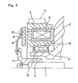
- Fig. 5 is a view showing the rotational driving structure of a rotatable shaft 1 of a compressor.
- This rotatable shaft 1 is rotationally supported within a casing 2 by a rolling bearing not shown in the figure.
- a follower pulley 4 is rotationally supported by a double-row radial ball bearing 5 around a supporting cylinder member 3, which is an instance of the supporting member as recited in a claim, the external surface of the end portion of this casing 2.
- This follower pulley 4 is designed in the form of a circular ring having a horseshoe cross section within whose inner space is arranged a solenoid 6 which is fixed to the end surface of the above casing 2.
- an attachment bracket 7 is fixed to the end portion of the above rotatable shaft 1 projected from the above casing 2 while an annular plate 8 made of a magnetic material is supported by a sheet spring 9 around this attachment bracket 7.
- this annular plate 8 is located separate from the above driven pulley 4 by the elasticity of the above board spring 9 as illustrated in Fig. 5.
- this annular plate 8 is attracted and stuck to this follower pulley 4 to allow the transmission of a rotation force from this follower pulley 4 to the above rotatable shaft 1.
- the above solenoid 6, the above annular plate 8 and the above sheet spring 9 serve as an electromagnetic clutch 10, in combination, for engaging and disengaging the above follower pulley 4 with the above rotatable shaft 1.
- Figs. 6 and 7 shows the second example of the conventional structures as described in JP Patent Publication No. Tokukai Hei 9-119510.
- a single-row four-point contact type radial ball bearing 14 is used to support, around the supporting structure not shown in the figure, a follower pulley 4a formed by bending process, e.g., by pressing a metallic plate and the like process.
- This radial ball bearing 14 is provided with an outer race 15 and an inner race 16 which are supported to be concentric with each other, and a plurality of balls 17 and 17. While the inner peripheral surface of the outer race 15 is formed with an outer raceway 18 over the entire circumference, the outer peripheral surface of the inner race 16 is formed with an inner raceway 19 over the entire circumference.
- Each of the respective outer raceways 18 and 19 has a so-called Gothic arch-like cross section in which arcs having curvature radii larger than a 1/2 of the diameter of the respective balls 17 and 17 intersect at the center position. Accordingly, each of the respective outer raceways 18 and 19 is in contact with the rolling contact surface of each of the respective balls 17 and 17 at two points, so that there are four contact points in total for each of the respective balls 17 and 17.
- the four-point contact type radial ball bearing 14 as described above has a higher rigidity against moment loads as compared with conventional single-row deep groove type radial ball bearings, and therefore even when a moment load is applied thereto the central axis of the above outer race 15 is hardly displaced from the central axis of the above inner race 16. Because of this, it is possible to lessen the partial wear of the endless belt 11 (refer to Fig. 5) rinning around the follower pulley 4 as compared with the case where a rotation support device for a compressor pulley is constructed by the use of a conventional single-row deep groove type radial ball bearing. Meanwhile, the above JP Patent Publication No.
- Tokukai Hei 11-336795 describes a structure in which a four-point contact type radial ball bearing as described above is installed in the rotatable supporting structure of a follower pulley for driving a compressor while an electromagnetic clutch is further provided between this follower pulley and the rotatable shaft of the compressor.
- This three-point contact type ball bearing 14a is provided with an inner raceway 19a having an arcuate cross sectional profile with a single curvature radius on the outer peripheral surface of this inner race 16a, and an outer raceway 18 having a Gothic arch-like cross sectional profile and making in contact with the rolling contact surface of the above ball 17 at two points on the inner peripheral surface of the above outer race 15 in the same manner as the four-point contact type radial ball bearing 14 as illustrated in Fig. 7.
- this three-point contact type ball bearing 14a for supporting a compressor pulley it is also possible to lessen the partial wear of the endless belt 11 (refer to Fig.
- JP Patent Publication No. Tokukai 2001-208081 describes a single-row deep groove type radial ball bearing having a cross sectional profile of each of the inner raceway and the outer raceway in which arcs having different curvature radii are smoothly joined in the form of a composite arc.
- the rolling contact surface of each ball is in contact with each of the inner raceway and the outer raceway at one point, i.e., as a two-point contact type, and therefore the rigidity against moment loads is considered as smaller than that of the three-point contact type or the four-point contact type as described above.
- the present invention has been made in order to provide a rotation support device for a compressor pulley having an excellent durability by assuring the rigidity of a radial ball bearing against moment loads, preventing ball from riding over the end edge of the raceway and preventing the rotational resistance and the internal heat generation from increasing.
- the rotation support device for a compressor pulley of this invention comprises, in the same manner as the prior art rotation support device for a compressor pulley, a rotatable shaft of a compressor, a stationary supporting member located around this rotatable shaft, a rolling bearing supported by this supporting member, and a pulley rotationally supported around this supporting member by this rolling bearing for having an endless belt run therearound.
- the above rolling bearing is then provided with an inner race having an inner raceway, an outer race having an outer raceway and a plurality of balls rollingly supported between the inner raceway and the outer raceway, such that the outer peripheral surface of the inner raceway is shaped to come in contact with a rolling contact surface of the balls at one or two points and that the inner peripheral surface of the outer raceway is shaped to come in contact with a rolling contact surface of the balls at one or two points, and that one raceway of the inner raceway and the outer raceway is in contact with the rolling contact surface of each ball at two points while the other raceway of the inner raceway and the outer raceway is in contact with the rolling contact surface of each ball at one point to form a single-row three-point contact type radial ball bearing.
- the cross sectional profile of the other raceway being in contact with the rolling contact surface of each ball at one point is a composite arc formed by smoothly joining a plurality of arcs having different curvature radii, in which the curvature radius of the composite arc is small in the center side in the width direction while the curvature radius of the composite arc in the width direction is large near the opposite edges.
- the curvature radius of the cross sectional profile of the one raceway being in contact with the rolling contact surface of each ball at two points is 0.53 to 0.57 times the diameter of the respective balls while the respective curvature radii of the cross sectional profile of the other raceway being in contact with the rolling contact surface of each ball at one point is 0.505 to 0.560 times the diameter of the respective balls.
- the present invention as recited above may be combined with one or more structures of the following structures 1 ⁇ 5 ⁇ .
- the cross sectional profile of the other raceway being in contact with the rolling contact surface of each of the above balls at one point is designed as a composite arc formed by a plurality of smoothly joining arcs having different curvature radii respectively, and in addition to this, the curvature radius in the center side in the width direction is smaller while the curvature radius is larger near the opposite edges in the width direction. For this reason, even when a heavy moment load is applied, the above respective balls hardly ride over the end edges in the width direction of the above other raceway and therefore preventing an excessive surface pressure from being applied to the rolling contact surface.
- the curvature radius in cross section of the one raceway being in contact with the rolling contact surface of each of the above balls at two points is limited to the range of 0.53 to 0.57 times the diameter of the respective balls while the respective curvature radii in cross section of the other raceway being in contact with the rolling contact surface of each of the above balls at one point is limited to the range of 0.505 to 0.560 times the diameter of the respective balls, and therefore it is possible to maintain the contact condition well in the rolling contact surfaces between the rolling contact surface of each ball and the respective raceways.
- the contact ellipse of the rolling contact surface becomes excessively large so that the rotational resistance and the internal heat generation possibly tends to increase.
- the contact ellipse of the rolling contact surface becomes excessively small so that it becomes likely to cause damage such as premature flaking due to the increase in the contact pressure.
- the durability of the above radial ball bearing can be furthermore improved by combining one or more structures of the above structures 1 ⁇ 5 ⁇ .
- the life of the grease is elongated to improve the durability of the above radial ball bearing.
- Figs. 1 and 2 show a first example of the embodiment in accordance with the present invention.
- the characteristic features of the present invention reside in assuring the durability of a radial ball bearing 14b of a structure which is used as a three-point contact type radial ball bearing 14b for rotationally supporting a follower pulley 4b around a stationary supporting member such as a supporting cylinder member 3 of a casing 2.
- the structures and the function of the other members are similar to those of the prior art structure as illustrated in Fig. 5, and therefore, while redundant explanation is not repeated or is simplified, the following description is focused on the characteristic structure of this example.
- the cross sectional profile of the inner raceway 19b includes a composite arc formed by smoothly joining arcs having different curvature radii R 1 and R 2 larger than a 1/2 of the diameter of the respective balls 17a with different centers of curvature respectively, and in addition to this, the curvature radius R 1 in the center side in the width direction is smaller while the curvature radius R 2 near the opposite edges in the width direction is larger (R 1 ⁇ R 2 ).
- the above outer raceway 18a is in contact with the rolling contact surface of each of the respective balls 17a at two points while the above inner raceway 19b is in contact the rolling contact surface of each of the respective balls 17a at one point, so that there are three contact points in total for each of the respective balls 17a.
- the rest angle ⁇ is selected to be 20 degrees which represents the differential angle between the center of this outer raceway 18a and the locations of the rolling contact surfaces with which the above outer raceway 18a rollingly engages a respective ball 17a.
- the above outer race 15a and the inner race 16b are assembled with a plurality of balls 17a to form the above radial ball bearing 14b, there is a positive or negative radial clearance in this radial ball bearing 14b.
- the positive radial clearance even when it exists, is limited to no larger than 0.2 % of the diameter Dp of the pitch circle of the above radial ball bearing 14b or no larger than 1.5 % of the diameter Da of the respective balls 17a.
- the above outer race 15a and the inner race 16b are treated by a high temperature tempering process (annealing process) at 190°C to 230°C or 230°C to 270°C in accordance with the usage environment for the purpose of improving the rolling contact fatigue lives of the above outer raceway 18a and the inner raceway 19b is improved.
- a nominal value is selected as a target temperature, e.g., 200°C, 210°C, 220°C, 240°C, 250°C, 260°C and the like in the above-mentioned temperature range.
- a relief groove 20 is formed in the center position in the width direction of the outer raceway 18a that is in contact with the rolling contact surface of each of the above balls 17a at two points, for the purpose of avoiding interference with a tool used during machining of this outer raceway 18a.
- the relief groove 20 as described above can be omitted with as in the prior art structure shown in Fig. 7.
- the above wall thickness T 15 is equal to the distance between the bottom of this relief groove 20 and the outer peripheral surface of the above outer race 15a.
- the dimension of the groove depth of the outer raceway 18a is preferred to be at least 18 % of the diameter Da of the respective balls 17a.
- the dimension of the groove depth of the outer raceway 18a is equal to the distance H from the bottom of the curve having the above curvature radius Ro to the edge of the above outer raceway 18a (if a chamfer exists, to the edge of the chamfer) as illustrated in Fig. 3.
- the groove depth H as defined in this manner, to be at least 18 % of the diameter Da of the respective balls 17a, it is possible to prevent the rolling contact surface of the respective balls 17a from riding over the end edge of the above outer raceway 18a. Consequently, it is possible to prevent an excessive surface pressure due to the edge load from being applied to the rolling contact surface of the respective balls 17a, to assure the rolling contact fatigue lives of the respective rolling contact surfaces and thereby improve the durability of the above radial ball bearing 14b. The reason of this will be explained with reference to Fig. 3.
- a pair of contact ellipses 33 and 33 exist, as well known, in the vicinity of the contact points between the rolling contact surface of each ball 17a and the above outer raceway 18a and in the left and right sides of this outer raceway 18a (the left and right direction is considered in relation to Fig. 3).
- the sizes of the respective contact ellipses 33 and 33 change depending on the radial load and the moment load applied to the above radial ball bearing 14b. When a moment load is applied, the above-described pair of the left and right contact ellipses 33 and 33 become different in size.
- the inventors of the present invention conducted experiments for determining the relationship between the effective radial clearance and the height of the contact ellipses 33 and 33 (refer to Fig. 3) by using a four-point contact type radial ball bearing which was driven under the application of a moment load, though not equivalent to the three-point contact type radial ball bearing 14b in accordance with this example.
- the maximum ratio of the height h of the contact ellipse 33 to the diameter Da of the respective balls 17a was 18 % in the case where the effective radial clearance of the above four-point contact type radial ball bearing was 0.020 mm (the maximum value of the effective radial clearance of the four-point contact type radial ball bearing used in the temperature environment at -40°C to 160°C).
- the maximum ratio (H/Da) of the groove depth H to the diameter Da of the respective balls 17a is preferably 40% or less.
- seal rings 22 and 22 engage, at their outer peripheral edges, respectively with locking grooves 21 and 21 of the inner peripheral surface of the above outer race 15a at the opposite ends thereof.
- the respective seal rings 22 and 22 are formed respectively of a resilient member 24 which is reinforced with a core metal 23 so that the outer peripheral edge of this resilient member 24 resiliently engages the respective locking grooves 21 and 21.
- the distal edge portion of each seal lip 25 provided at the inner peripheral edge portion of this resilient member 24 is let slidably contact part of the above inner race 16b over the entire circumference in order to closely seal both the opposite openings of the inner space 26 in which the respective balls 17a are placed.
- the above resilient member 24 forming the respective seal rings 22 and 22 is preferably made of a nitrile rubber or an acrylic rubber.
- an ether base grease (not shown in the figure) having a viscosity of 70 to 90 mm 2 /s(cst), preferably, 77 to 82 mm 2 /s, at an atmospheric temperature of 40°C, as described in the above 2 ⁇ .
- This grease is preferably made of a composite oil comprising an ether as a base oil with a thickener of an urea such as diurea and including at least ZnDTC as an additive.
- This type of grease serves to form an effective oil film on the rolling contact section between the rolling contact surfaces of the above respective balls 17a and the above respective raceways 18a and 19b to make a contribution to the assuring of the rolling contact fatigue lives of the respective the raceways 18a and 19b. That is, if generation of heat inside of the above radial ball bearing 14b becomes significant because of the operation under a substantial moment load and so forth, the life of the grease in the above internal space 26 is shortened due to thermal degradation. Since the grease having the above composition has an excellent heat resistance, the life is little shortened even with a temperature rise in the above internal space 26, and therefore the use of the grease can make a contribution to the assuring of the rolling contact fatigue life of the above radial ball bearing 14b. Incidentally, besides those having the composition as described above, ester base and poly- ⁇ -olefin base composite oils are suitable for use as a base oil of the grease to be inserted into the above internal space 26.
- the respective balls 17a are rollingly supported by a retainer 27 of the crown type.
- This retainer 27 is formed in a body by injection moulding a synthetic resin such as a polyamid resin, a poly-phenylene-sulfide resin and the like containing glass fibers in an amount of 5 weight % to 35 weight % (preferably 10 weight % to 25 weight %) as a reinforcement member.
- each pocket 29 in the circumferential direction of the above retainer 27 is at least 1.03 times of the diameter Da of the respective balls 17a.
- the orbital speeds of the respective balls 17a depend on the contact angle with the above outer raceway 18a and the inner raceway 19b.
- the contact angle of each ball 17a slightly changes in regard to the circumferential direction of the above outer raceway 18a and the inner raceway 19b.
- the orbital speeds of the above respective balls 17a become uneven in the circumferential direction. In other words, the orbital speed is increased or decreased in a subtle manner depending upon the phase in the circumferential direction.
- each pocket 29 in the peripheral direction of the respective pocket 29 is at least 1.03 times the diameter Da of the above respective balls 17a as described above, it is possible to prevent the balls 17a supported in the respective pocket 29 from strongly being pushed against the inner surfaces of the respective pocket 29.
- the above inside dimension is 1.03 times the diameter Da of the above respective balls 17a, although the rolling contact surfaces of the respective balls 17a may be pushed against the inner surfaces of the respective pocket 29, the pushing force is very weak and can be sufficiently absorbed by a tolerable elastic deformation of the above craw member 32.
- the above inside dimension is at least 1.035 times the diameter Da of the above respective balls 17a, it is possible to effectively prevent the rolling contact surfaces of the respective balls 17a from being pushed against the inner surfaces of the respective pocket 29.
- the size of the entire inner diameter of the respective pockets 29 are increased, or alternatively the respective pockets 29 are designed as oblong circles elongated in the circumferential direction.
- the maximum value of the inside dimension in the circumferential direction is limited in accordance with the relationship with the diameter Da of the above respective balls 17a and taking into consideration the entire strength of the above retainer 27.
- the maximum value of the above inside dimension is limited up to 1.1 times this diameter Da, preferably up to 1.05 times.
- the technique of improving the durability of the retainer by increasing the inside dimension of the respective pocket 29 is applicable not only to the retainer of the crown type as illustrated but also to a machined retainer having rims at the both end in the axial direction.
- the radial ball bearing 14b having the structure as described above is inserted between the inner peripheral surface of the above follower pulley 4b and the supporting cylinder member 3 of the above casing 2 as illustrated in Fig. 1 to form the rotation support device for a compressor pulley in accordance with the present invention.
- a rotation support device for a compressor pulley is constructed in this manner, as illustrated in Fig. 1, there is provided a displacement d (an offset amount) in the axial direction (the lateral direction in Fig. 1) between the center position in the width direction (the chained line ⁇ in Fig.
- the durability of the above radial ball bearing 14b can be assured by selecting this offset amount ⁇ up to 40% (0.4Dp ⁇ ) of the diameter Dp (refer to Fig. 2) of the pitch circle of the above radial ball bearing 14b, preferably, up to 20% (0.2Dp ⁇ ), and furthermore preferably, up to 10% (0.1Dp ⁇ ).
- a moment load proportional to the above offset amount d is applied to the above radial ball bearing 14b through the above follower pulley 4b according to the tension of the above endless belt 11.
- the central axis of the inner race 16b and the central axis of the outer race 15a constituting this radial ball bearing 14b in combination tends to be misaligned (inclined) from each other.
- the moment load applied to the above outer race 15a through the above follower pulley 4b can be minimized by limiting the offset amount d as described above.
- the above radial ball bearing 14b installed in the rotation support device for a compressor pulley is of a three-point contact type, and therefore it is possible to minimize the increase in the rotational resistance and the internal heat generation, while assuring the rigidity of the radial ball bearing against moment loads.
- the rigidity against moment loads can be easily assured as compared with that of a two-point contact type.
- the cross sectional profile of the inner raceway 19b being in contact with the rolling contact surface of each of the above balls 17a at one point is designed as a composite arc formed by a plurality of smoothly joining arcs having different curvature radii R 1 and R 2 , and in addition to this, the curvature radius R 1 in the center side in the width direction is smaller while the curvature radius R 2 near the opposite edges in the width direction is larger. For this reason, even when a heavy moment load is applied, the above respective balls 17a hardly ride over the end edges in the width direction of the above inner raceway 19b and therefore preventing an excessive surface pressure from being applied to the rolling contact surface.
- the contact ellipse of the rolling contact section becomes excessively large so that the rotational resistance and the internal heat generation possibly tends to increase.
- the contact ellipse of the rolling contact section becomes excessively small so that it becomes likely to cause damage such as premature flaking due to the increase in the contact pressure.
- the present invention is applicable also to a structure without an electromagnetic clutch as long as the structure serves to transmit a rotation force from a pulley to a rotatable shaft. That is, in the case of an variable displacement swash plate compressor for example as described in JP Patent Publication No. Tokukai Hei 11-210619 or JP Utility Model Publication No. Sho 64-27482, the rotating torque of the rotatable shaft of the compressor can be significantly small by setting a very small gradient angle of the swash plate (or by setting the gradient angle to zero). In the case of such a structure, as illustrated in Fig.
- the electromagnetic clutch may be dispensed with by linking a rotatable shaft 1 with a follower pulley 4c rotationally supported through a roller bearing 30 around a supporting cylinder member 3 formed at the end portion of a casing 2 to allow the transmission of a rotation force through a buffer member 31 serving as a torque tube unless an excessive torque is not applied.
- a buffer member 31 serving as a torque tube unless an excessive torque is not applied.
- the outer race 15a and the balls 17a is made of an iron base metallic material such as a carbon steel, a bearing steel, a stainless steel and the like
- this radial ball bearing 14b which is a single-row ball bearing is driven under an offset load (under a moment load)
- the surface pressure at the contact portion between the rolling contact surface of each ball 17a and each of the above inner raceway 19b and the outer raceway 18a becomes high. If the elastic deformation due to this surface pressure increases, the rolling contact fatigue life of the corresponding member is shortened so that the durability of the above radial ball bearing 14b is degraded, and for this reason the above nitriding treatment is given in order to improve the surface hardness of the corresponding member, suppress the above elastic deformation and inhibit the wear.
- the nitriding treatment is a solution treatment of C and N by which the surface hardness increases after the treatment. Accordingly, nitrided layers having a high degree of hardness are formed on the surfaces of the above inner race 16b, the above outer race 15a and the above respective balls 17a by the nitriding treatment. Meanwhile, in regard to the above inner race 16b and the outer race 15a, as long as nitrided layers are formed on the above inner raceway 19b and the outer raceway 18a, the other portions are not necessarily nitrided.
- the elastic deformation due to the above surface pressure does not equally appears in the above inner race 16b, the outer race 15a and the balls 17a but the degree of deformation depends on the profile and the material.
- the outer raceway 18a and the inner raceway 19b are easily elastically deformed while the balls 17a are not easily elastically deformed in the case where they are made of the same material. Accordingly, while it is preferred to give the above nitriding treatment to all the members, only some members such as only the above inner race 16b and the outer race 15a are treated depending upon the material, the size, the profile and the like.
- the above dimensional stabilization treatment is a thermal treatment used for the purpose of decreasing the remained austenite amount ⁇ R and, for example, conducted by gradually cooling the material of the above inner race 16b and the outer race 15a to decrease the remained austenite amount ⁇ R to 6 % or lower by volume after the above treatment.
- the dimension of the cross sectional profile of the radial ball bearing 14b in the lateral direction is 1.3 or more times the height of the same cross sectional profile in the radial direction as described the above 5 ⁇ , it is possible to increase the volume of the internal space of this radial ball bearing and therefore increase the amount of grease inserted in this internal space. Then, as a result, the durability life of this grease is elongated to improve the durability of the above radial ball bearing 14b.
- Fig. 4 shows a second example of the embodiment in accordance with the present invention. While the first example of the embodiment as described above is applicable to a three-point contact type radial ball bearing in which the rolling contact surface of each of the balls 17a and the inner raceway 19b (refer to Fig. 4) at one point, this example is applicable to a three-point contact type radial ball bearing in which the rolling contact surface of each of the balls 17a and the outer raceway 18b at one point.
- the cross sectional profile of the inner raceway 19c is a so-called Gothic arch-like cross section in which arcs having a curvature radius Ri larger than a 1/2 of the diameter Da of the respective ball 17a and different centers of curvature intersect at the middle portion.
- the cross sectional profile of the outer raceway 18b includes a composite arc formed by smoothly joining arcs having different curvature radii R 1 and R 2 larger than a 1/2 of the diameter of the respective balls 17a, and in addition to this, the curvature radius R 1 in the center side in the width direction is smaller while the curvature radius R 2 near the opposite edges in the width direction is larger (R 1 ⁇ R 2 ).
- the structures and the function of the other members are similar to those of the first example as described above, and therefore redundant explanation is omitted.
- the rotation support device for a compressor pulley in accordance with the present invention which is constructed and operated as mentioned above, it is possible to secure the tolerable moment load and to suppress heat generation and wear during operation without increasing the dimension in the axial direction.
- the present invention contributes to downsizing and improving the performance of a variety of mechanical devices such as compressors for use in an air-conditioning system of a vehicle, e.g., by increasing the life of the rolling bearing installed in the above rotation support device for a compressor pulley and the life of an endless belt extending around a pulley supported by this rolling bearing.
Landscapes
- Engineering & Computer Science (AREA)
- General Engineering & Computer Science (AREA)
- Mechanical Engineering (AREA)
- Manufacturing & Machinery (AREA)
- Rolling Contact Bearings (AREA)
Abstract
A rotation support device for a compressor pulley, wherein a
three-point contact radial ball bearing (14b) is used as a rolling bearing for
supporting a driven pulley, the cross sectional shape of an inner ring raceway
track (19b) coming into contact, at one point, with the rolling contact surface of
each ball (17a) is formed in a composite arc by smoothly and continuously
connecting arcs with different radii of curvature R1 and R2 to each other, and
the radius of curvature R1 on a center side in the width direction is made
smaller and the radii of curvature R2 on the both end sides in the width
direction are made larger (R1<R2) whereby the durability of the rolling bearing
for supporting the driven pulley can be assured while reducing the size of the
rolling bearing.
Description
- The present invention is related to a rotation support device for a compressor pulley for rotationally supporting a follower pulley around a stationary supporting member such as a housing of a compressor in an air-conditioning system of a vehicle, and installed for use in the rotation driving device of this compressor.
- Compressors for use in an air-conditioning system of a vehicle are rotationally driven by a traction engine to compress a refrigerant. For this purpose, an endless belt running around a follower pulley fixed at the end portion of the rotatable shaft of this compressor and a driven pulley fixed at the end portion of a crank shaft for the above traction engine in order to rotationally drive the above rotatable shaft by the rotation of this endless belt.
- Fig. 5 is a view showing the rotational driving structure of a
rotatable shaft 1 of a compressor. Thisrotatable shaft 1 is rotationally supported within acasing 2 by a rolling bearing not shown in the figure. Afollower pulley 4 is rotationally supported by a double-row radial ball bearing 5 around a supportingcylinder member 3, which is an instance of the supporting member as recited in a claim, the external surface of the end portion of thiscasing 2. Thisfollower pulley 4 is designed in the form of a circular ring having a horseshoe cross section within whose inner space is arranged asolenoid 6 which is fixed to the end surface of theabove casing 2. On the other hand, an attachment bracket 7 is fixed to the end portion of the aboverotatable shaft 1 projected from theabove casing 2 while anannular plate 8 made of a magnetic material is supported by a sheet spring 9 around this attachment bracket 7. When theabove solenoid 6 is not energized, thisannular plate 8 is located separate from the above drivenpulley 4 by the elasticity of the above board spring 9 as illustrated in Fig. 5. However, when theabove solenoid 6 is energized, thisannular plate 8 is attracted and stuck to thisfollower pulley 4 to allow the transmission of a rotation force from thisfollower pulley 4 to the aboverotatable shaft 1. Namely, theabove solenoid 6, the aboveannular plate 8 and the above sheet spring 9 serve as anelectromagnetic clutch 10, in combination, for engaging and disengaging theabove follower pulley 4 with the aboverotatable shaft 1. - In the case of the above structure in which the double-row radial ball bearing 5 is used to rotationally support the
follower pulley 4, even when some unbalanced load is applied to thisfollower pulley 4 from the endless belt 11 (shown with a phantom line) running around thisfollower pulley 4, there is little possibility of incurring the misalignment (inclination) between the central axis of theouter race 12 and the central axis of theinner race 13 constituting the above double-row radial ball bearing 5. Accordingly, it is possible to assure the durability of the above double-row radial ball bearing 5 and also to avoid the partial wear of the aboveendless belt 11 by preventing the center of rotation of theabove follower pulley 4 from being inclined. - By the use of the above double-row radial ball bearing 5, however, it is inevitable that the dimension is increased in the axial direction. The rotatable supporting structure of the
follower pulley 4 has to be located within a limited space in many cases, and therefore it is undesirable that the dimension is increased in the axial direction. In addition to this, the increased dimension in the axial direction results in the increased cost of the respective constituent parts. - It becomes easy to install the rotatable supporting structure in a limited space by making use of a single-row deep groove type radial ball bearing, in place of the double-row radial ball bearing 5 as described above, as a rolling bearing for supporting the
above follower pulley 4. However, in the case of a simple single-row deep groove type radial ball bearing, when a moment load is applied to theabove follower pulley 4, there is only a small resisting force to prevent thefollower pulley 4 from being inclined to increase the degree of misalignment between the central axis of the outer race and the central axis of the inner race constituting the above double-row radial ball bearing. This results not only in an insufficiency in durability of the above radial ball bearing, but also in a substantial partial wear of theendless belt 11 running around theabove follower pulley 4. - Taking into consideration the above circumstances, it is proposed in the prior art to use a single-row four-point contact type radial ball bearing, for example, as described in JP Patent Publication Nos. Tokukai Hei 9-119510 and Tokukai Hei 11-336795. Among them, Figs. 6 and 7 shows the second example of the conventional structures as described in JP Patent Publication No. Tokukai Hei 9-119510.
- In the case of the second example of the conventional structures, a single-row four-point contact type
radial ball bearing 14 is used to support, around the supporting structure not shown in the figure, a follower pulley 4a formed by bending process, e.g., by pressing a metallic plate and the like process. This radial ball bearing 14 is provided with anouter race 15 and aninner race 16 which are supported to be concentric with each other, and a plurality of 17 and 17. While the inner peripheral surface of theballs outer race 15 is formed with anouter raceway 18 over the entire circumference, the outer peripheral surface of theinner race 16 is formed with aninner raceway 19 over the entire circumference. Each of the respective 18 and 19 has a so-called Gothic arch-like cross section in which arcs having curvature radii larger than a 1/2 of the diameter of theouter raceways 17 and 17 intersect at the center position. Accordingly, each of the respectiverespective balls 18 and 19 is in contact with the rolling contact surface of each of theouter raceways 17 and 17 at two points, so that there are four contact points in total for each of therespective balls 17 and 17.respective balls - The four-point contact type radial ball bearing 14 as described above has a higher rigidity against moment loads as compared with conventional single-row deep groove type radial ball bearings, and therefore even when a moment load is applied thereto the central axis of the above
outer race 15 is hardly displaced from the central axis of the aboveinner race 16. Because of this, it is possible to lessen the partial wear of the endless belt 11 (refer to Fig. 5) rinning around thefollower pulley 4 as compared with the case where a rotation support device for a compressor pulley is constructed by the use of a conventional single-row deep groove type radial ball bearing. Meanwhile, the above JP Patent Publication No. Tokukai Hei 11-336795 describes a structure in which a four-point contact type radial ball bearing as described above is installed in the rotatable supporting structure of a follower pulley for driving a compressor while an electromagnetic clutch is further provided between this follower pulley and the rotatable shaft of the compressor. - Also in the case of the single-row three-point contact type ball bearing 14a as illustrated in Fig. 8, the rigidity against moment loads is high as compared with conventional single-row deep groove type radial ball bearings, and therefore even when a moment load is applied thereto the central axis of the above
outer race 15 is hardly displaced from the central axis of the above inner race 16a. This three-point contact type ball bearing 14a is provided with an inner raceway 19a having an arcuate cross sectional profile with a single curvature radius on the outer peripheral surface of this inner race 16a, and anouter raceway 18 having a Gothic arch-like cross sectional profile and making in contact with the rolling contact surface of theabove ball 17 at two points on the inner peripheral surface of the aboveouter race 15 in the same manner as the four-point contact type radial ball bearing 14 as illustrated in Fig. 7. In the case of this three-point contact type ball bearing 14a for supporting a compressor pulley, it is also possible to lessen the partial wear of the endless belt 11 (refer to Fig. 5) running around thefollower pulley 4 as compared with the case where a rotation support device for a compressor pulley is constructed by the use of a conventional single-row deep groove type radial ball bearing. This applies also to a three-point contact type ball bearing in which the rolling contact surface of each ball is in contact respectively with the outer raceway at one point and with the inner raceway at two points in a reverse manner to the structure of Fig. 8. - As mentioned above, when a three-point contact type or a four-point contact type radial ball bearing is used in the rotatable supporting structure of a follower pulley for driving a compressor, there is a possibility of achieving both the reduction of the size and weight thereof and the durability thereof at a higher level. However, in the case of the three-point contact type or four-point contact type radial ball bearings as described above, there may occur the following shortcomings respectively.
- First, in the case of the three-point contact type radial ball bearing among these two types, it is desired to decrease the curvature radius of the cross sectional profile of the raceway being in contact with the rolling contact surface of each ball at one point to 0.505 to 0.520 times the diameter (50.5 to 52.0 %) of each ball for the purpose of assuring the rigidity against radial loads. However, if the curvature radius is decreased in this manner, it becomes likely that the respective balls ride over the edge of the above raceways so that an excessive surface pressure due to the edge load may be applied to the rolling contact surfaces of the respective balls. As a result, it becomes likely to cause damage such as premature flaking on the rolling contact surfaces of the respective balls.
- On the other hand, in the case of the four-point contact type radial ball bearing, the rigidity against moment loads can be assured but then the rotational resistance and the internal heat generation tend to increase due to the larger number of contact points between the raceways and the respective balls. In addition to this, when a heavy moment load is applied, there is a possibility of displacing the above contact points toward the edge in the width direction. Because of the displacement, a micro slip tends to occur at the respective contact points so that internal heat generation and wear may be increased due to the micro slip.
- Incidentally, JP Patent Publication No. Tokukai 2001-208081 describes a single-row deep groove type radial ball bearing having a cross sectional profile of each of the inner raceway and the outer raceway in which arcs having different curvature radii are smoothly joined in the form of a composite arc. However, in the case of the single-row deep groove type radial ball bearing as described in this publication, the rolling contact surface of each ball is in contact with each of the inner raceway and the outer raceway at one point, i.e., as a two-point contact type, and therefore the rigidity against moment loads is considered as smaller than that of the three-point contact type or the four-point contact type as described above.
- Taking into consideration the above situation, the present invention has been made in order to provide a rotation support device for a compressor pulley having an excellent durability by assuring the rigidity of a radial ball bearing against moment loads, preventing ball from riding over the end edge of the raceway and preventing the rotational resistance and the internal heat generation from increasing.
- The rotation support device for a compressor pulley of this invention comprises, in the same manner as the prior art rotation support device for a compressor pulley, a rotatable shaft of a compressor, a stationary supporting member located around this rotatable shaft, a rolling bearing supported by this supporting member, and a pulley rotationally supported around this supporting member by this rolling bearing for having an endless belt run therearound.
- Then, as illustrated in Fig. 8, the above rolling bearing is then provided with an inner race having an inner raceway, an outer race having an outer raceway and a plurality of balls rollingly supported between the inner raceway and the outer raceway, such that the outer peripheral surface of the inner raceway is shaped to come in contact with a rolling contact surface of the balls at one or two points and that the inner peripheral surface of the outer raceway is shaped to come in contact with a rolling contact surface of the balls at one or two points, and that one raceway of the inner raceway and the outer raceway is in contact with the rolling contact surface of each ball at two points while the other raceway of the inner raceway and the outer raceway is in contact with the rolling contact surface of each ball at one point to form a single-row three-point contact type radial ball bearing.
- Particularly, in the rotation support device for a compressor pulley of this invention, the cross sectional profile of the other raceway being in contact with the rolling contact surface of each ball at one point is a composite arc formed by smoothly joining a plurality of arcs having different curvature radii, in which the curvature radius of the composite arc is small in the center side in the width direction while the curvature radius of the composite arc in the width direction is large near the opposite edges.
- Also, more preferably, the curvature radius of the cross sectional profile of the one raceway being in contact with the rolling contact surface of each ball at two points is 0.53 to 0.57 times the diameter of the respective balls while the respective curvature radii of the cross sectional profile of the other raceway being in contact with the rolling contact surface of each ball at one point is 0.505 to 0.560 times the diameter of the respective balls.
- Furthermore, the present invention as recited above may be combined with one or more structures of the following
structures 1 ○∼5 ○. - 1 ○ With the inner and outer raceways, the groove depth of the one raceway being in contact with the rolling contact surface of each ball at two points is at least 18 % of the diameter of the balls.
- 2 ○ The radial ball bearing is filled with a grease made of a composite oil comprising one or more selected from the group of an ether, an ester and a poly-alpha-olefin as a base oil with a thickener of an urea and including as an additive at least ZnDTC (zinc dithiocarbamate which is an extreme pressure additive).
- 3 ○ At least one of a nitriding treatment and a dimensional stabilization treatment is given to at least one of the inner race and the outer race and balls.
- 4 ○ Each ball is rollingly supported in a pocket provided in a retainer while the inside dimension of the pocket in the circumferential direction is 1.03 or more times of the diameter of the respective balls.
- 5 ○ The width dimension in cross section of the radial ball bearing is also 1.3 or more times of the diameter in the radial direction of the radial ball bearing.
-
- In accordance with the rotation support device for a compressor pulley of the present invention as constructed above, it is possible to prevent the balls in the radial ball bearing from riding even the end edge of the raceways and to minimize the increase in the rotational resistance and the internal heat generation, while assuring the rigidity of the radial ball bearing against moment loads. Namely, since the above radial ball bearing is of a three-point contact type, the rigidity against moment loads can be easily assured as compared with that of a two-point contact type. Also, in addition to this, it is possible to minimize the increase in the rotational resistance and the internal heat generation as compared with that of a four-point contact type.
- Furthermore, the cross sectional profile of the other raceway being in contact with the rolling contact surface of each of the above balls at one point is designed as a composite arc formed by a plurality of smoothly joining arcs having different curvature radii respectively, and in addition to this, the curvature radius in the center side in the width direction is smaller while the curvature radius is larger near the opposite edges in the width direction. For this reason, even when a heavy moment load is applied, the above respective balls hardly ride over the end edges in the width direction of the above other raceway and therefore preventing an excessive surface pressure from being applied to the rolling contact surface. As a result, it is possible to inhibit the inclination of the above follower pulley and the outer race relative to the inner race and assure the rolling contact fatigue life of the above radial ball bearing and the durability of this radial ball bearing. In addition to this, it is also possible to inhibit the partial wear of the endless belt running around the above pulley and assure the durability of this endless belt.
- Furthermore, the curvature radius in cross section of the one raceway being in contact with the rolling contact surface of each of the above balls at two points is limited to the range of 0.53 to 0.57 times the diameter of the respective balls while the respective curvature radii in cross section of the other raceway being in contact with the rolling contact surface of each of the above balls at one point is limited to the range of 0.505 to 0.560 times the diameter of the respective balls, and therefore it is possible to maintain the contact condition well in the rolling contact surfaces between the rolling contact surface of each ball and the respective raceways. That is, if the curvature radius in cross section of the above one raceway is smaller than 0.53 time the diameter of the respective balls, or if the respective curvature radii in cross section of the above other raceway are smaller than 0.505 times the diameter of the respective balls, the contact ellipse of the rolling contact surface becomes excessively large so that the rotational resistance and the internal heat generation possibly tends to increase. On the other hand, if the curvature radius in cross section of the above one raceway is larger than 0.57 times the diameter of the respective balls, or if the respective curvature radii in cross section of the above other raceway are larger than 0.560 times the diameter Da of the respective balls, the contact ellipse of the rolling contact surface becomes excessively small so that it becomes likely to cause damage such as premature flaking due to the increase in the contact pressure.
- In addition to this, the durability of the above radial ball bearing can be furthermore improved by combining one or more structures of the
above structures 1 ○∼5 ○. - First, by securing the groove depth of the one raceway being in contact with the rolling contact surface of each ball at two points to be no less than 18 % of the diameter of the respective balls as described in the 1 ○, it is possible to prevent the rolling contact surface of the respective balls from riding over the end edge of the above one raceway. As a result, it is possible to prevent an excessive surface pressure from being applied to the rolling contact surface of the respective balls, assure the rolling contact fatigue lives of the respective rolling contact surfaces and thereby improve the durability of the above radial ball bearing.
- Also, by the use of a grease having the predetermined composition as described in the 2 ○, the life of the grease is elongated to improve the durability of the above radial ball bearing.
- Furthermore, if a nitriding treatment or a dimensional stabilization treatment is conducted as described in the 3 ○, it is possible to improve the rolling contact fatigue lives of the elements given the treatment and other elements contacting the elements and therefore improve the durability of the above radial ball bearing.
- Still further, by securing the inside dimension of the respective pockets of the retainer as described in the 4 ○, it is possible to prevent each pocket from being strongly pressed by the balls supported by the pocket, avoid the damage on the above retainer and improve the durability of the above radial ball bearing.
- Still further, if the width dimension of the cross sectional profile of the radial ball bearing is secured as described the above 5 ○, it is possible to increase the volume of the internal space of this radial ball bearing and therefore increase the amount of a grease filled in this internal space. As a result, the durability life of this grease can be elongated to improve the durability of the above radial ball bearing.
-
- Fig. 1 is a partial sectional view showing a first example of the embodiment of the present invention.
- Fig. 2 is a partial enlarged sectional view separately showing a radial ball bearing.
- Fig. 3 is a partial sectional view showing a raceway with which the concept of a groove depth is explained.
- Fig. 4 is a partial sectional view showing a second example of the embodiment of the present invention in the same manner as Fig. 2.
- Fig. 5 is a partial sectional view showing a first example of a conventional structure.
- Fig. 6 is a sectional view showing a second example of the conventional structure.
- Fig. 7 is a sectional view separately showing a four-point contact type radial ball bearing.
- Fig. 8 is a sectional view separately showing a three-point contact type radial ball bearing.
- Fig. 9 is a sectional view showing another exemplary structure to which the present invention is applicable.
-
- Figs. 1 and 2 show a first example of the embodiment in accordance with the present invention. The characteristic features of the present invention reside in assuring the durability of a
radial ball bearing 14b of a structure which is used as a three-point contact typeradial ball bearing 14b for rotationally supporting afollower pulley 4b around a stationary supporting member such as a supportingcylinder member 3 of acasing 2. The structures and the function of the other members are similar to those of the prior art structure as illustrated in Fig. 5, and therefore, while redundant explanation is not repeated or is simplified, the following description is focused on the characteristic structure of this example. - The above described
radial ball bearing 14b is provided with anouter race 15a and aninner race 16b which are supported to be concentric with each other, and a plurality ofballs 17a. While the inner peripheral surface of theouter race 15a is formed with anouter raceway 18a over the entire circumference, the outer peripheral surface of theinner race 16b is formed with aninner raceway 19b over the entire circumference. With theouter raceway 18a and theinner raceway 19b, the cross sectional profile of theouter raceway 18a, is a so-called Gothic arch-like cross section in which arcs having a curvature radius Ro larger than 1/2 of the diameter Da of therespective ball 17a and different centers of curvature intersect each other at the center position. Meanwhile, the curvature radius Ro of the aboveouter raceway 18a is desirably limited to the range of 0.53 to 0.57 times the diameter Da of therespective balls 17a (Ro = 0.53Da to 0.57Da). - On the other hand, of the above
outer raceway 18a and theinner raceway 19b, the cross sectional profile of theinner raceway 19b includes a composite arc formed by smoothly joining arcs having different curvature radii R1 and R2 larger than a 1/2 of the diameter of therespective balls 17a with different centers of curvature respectively, and in addition to this, the curvature radius R1 in the center side in the width direction is smaller while the curvature radius R2 near the opposite edges in the width direction is larger (R1<R2). Namely, in the case of this example, the above curvature radius R1 in the center side in the width direction is 0.505 times the diameter Da of therespective balls 17a (R1 = 0.505Da) while the curvature radius R2 near the opposite edges in the width direction is 0.560 times the diameter Da (R2 = 0.560Da). For example, the respective curvature radii R1 and R2 are preferably limited to the range of 0.505 to 0.560 times the diameter Da of therespective balls 17a (R1 = 0.505Da to 0.56Da and R2 = 0.505Da to 0.56Da). - In the case where the respective elements are designed as described above, the above
outer raceway 18a is in contact with the rolling contact surface of each of therespective balls 17a at two points while the aboveinner raceway 19b is in contact the rolling contact surface of each of therespective balls 17a at one point, so that there are three contact points in total for each of therespective balls 17a. In the case of this example, the rest angle is selected to be 20 degrees which represents the differential angle between the center of thisouter raceway 18a and the locations of the rolling contact surfaces with which the aboveouter raceway 18a rollingly engages arespective ball 17a. Also, when the aboveouter race 15a and theinner race 16b are assembled with a plurality ofballs 17a to form the aboveradial ball bearing 14b, there is a positive or negative radial clearance in thisradial ball bearing 14b. The positive radial clearance, even when it exists, is limited to no larger than 0.2 % of the diameter Dp of the pitch circle of the aboveradial ball bearing 14b or no larger than 1.5 % of the diameter Da of therespective balls 17a. - Furthermore, the above
outer race 15a and theinner race 16b are treated by a high temperature tempering process (annealing process) at 190°C to 230°C or 230°C to 270°C in accordance with the usage environment for the purpose of improving the rolling contact fatigue lives of the aboveouter raceway 18a and theinner raceway 19b is improved. Incidentally, when the high temperature tempering process is actually performed, a nominal value is selected as a target temperature, e.g., 200°C, 210°C, 220°C, 240°C, 250°C, 260°C and the like in the above-mentioned temperature range. - Also, in the case of the example as illustrated, of the above
outer raceway 18a and theinner raceway 19b, arelief groove 20 is formed in the center position in the width direction of theouter raceway 18a that is in contact with the rolling contact surface of each of theabove balls 17a at two points, for the purpose of avoiding interference with a tool used during machining of thisouter raceway 18a. However, therelief groove 20 as described above can be omitted with as in the prior art structure shown in Fig. 7. Anyway, the wall thickness T15 of the aboveouter race 15a at the groove bottom (at the portion with the smallest wall thickness in the center of theouter raceway 18a) is at least 20 % of the diameter Da of therespective balls 17a as described above, preferably 20 % to 40 % of Da {T15 = (0.2 to 0.4)Da}. In the case where theabove relief groove 20 is formed, the above wall thickness T15 is equal to the distance between the bottom of thisrelief groove 20 and the outer peripheral surface of the aboveouter race 15a. By limiting the above wall thickness T15 to the above range, it is possible to prevent the outer diameter of the aboveradial ball bearing 14b from unnecessarily increasing and to assure the strength of thisouter race 15a while avoiding growth in size of theradial ball bearing 14b with the aboveouter race 15a. - Also, of the above
outer raceway 18a and theinner raceway 19b, the dimension of the groove depth of theouter raceway 18a, that is in contact with the rolling contact surface of each of theabove balls 17a at two points, is preferred to be at least 18 % of the diameter Da of therespective balls 17a. Incidentally, the dimension of the groove depth of theouter raceway 18a is equal to the distance H from the bottom of the curve having the above curvature radius Ro to the edge of the aboveouter raceway 18a (if a chamfer exists, to the edge of the chamfer) as illustrated in Fig. 3. By selecting the groove depth H, as defined in this manner, to be at least 18 % of the diameter Da of therespective balls 17a, it is possible to prevent the rolling contact surface of therespective balls 17a from riding over the end edge of the aboveouter raceway 18a. Consequently, it is possible to prevent an excessive surface pressure due to the edge load from being applied to the rolling contact surface of therespective balls 17a, to assure the rolling contact fatigue lives of the respective rolling contact surfaces and thereby improve the durability of the aboveradial ball bearing 14b. The reason of this will be explained with reference to Fig. 3. - A pair of
33 and 33 exist, as well known, in the vicinity of the contact points between the rolling contact surface of eachcontact ellipses ball 17a and the aboveouter raceway 18a and in the left and right sides of thisouter raceway 18a (the left and right direction is considered in relation to Fig. 3). The sizes of the 33 and 33 change depending on the radial load and the moment load applied to the aboverespective contact ellipses radial ball bearing 14b. When a moment load is applied, the above-described pair of the left and 33 and 33 become different in size. Anyway, an excessive surface pressure is not applied to the rolling contact surface of theright contact ellipses respective balls 17a as long as the 33 and 33 fall within the abovewhole contact ellipses outer raceway 18a, however, an excessive surface pressure due to the edge load is applied to the rolling contact surface if eithercontact ellipse 33 derails the aboveouter raceway 18a (more exactly speaking, although no contact ellipse is defined when derailing, the term "contact ellipse" is used also in the case where the contact point reaches the end edge for the sake of explanation). Accordingly, in order to assure the rolling contact fatigue lives of the rolling contact surfaces of therespective balls 17a and improve the durability of the aboveradial ball bearing 14b, it is necessary to prevent thecontact ellipses 33 from derailing the aboveouter raceway 18a or, in other words, from reaching the end edge of theraceway 18a. - Then, the inventors of the present invention conducted experiments for determining the relationship between the effective radial clearance and the height of the
contact ellipses 33 and 33 (refer to Fig. 3) by using a four-point contact type radial ball bearing which was driven under the application of a moment load, though not equivalent to the three-point contact typeradial ball bearing 14b in accordance with this example. From the results of the experiments, it was confirmed that the maximum ratio of the height h of thecontact ellipse 33 to the diameter Da of therespective balls 17a was 18 % in the case where the effective radial clearance of the above four-point contact type radial ball bearing was 0.020 mm (the maximum value of the effective radial clearance of the four-point contact type radial ball bearing used in the temperature environment at -40°C to 160°C). - From this fact, as described in the above 1 ○, of the above
outer raceway 18a and theinner raceway 19b, it is possible to prevent the rolling contact surfaces of therespective balls 17a from riding over the end edge of the aboveouter raceway 18a by securing at least 18 % of the diameter Da of therespective balls 17a for the dimension of the groove depth H of theouter raceway 18a, that is in contact with the rolling contact surface of each of theabove balls 17a at two points. If this riding is avoided, it is possible to prevent an excessive surface pressure from being applied to the rolling contact surface of therespective balls 17a, to assure the rolling contact fatigue lives of the respective rolling contact surfaces and thereby to improve the durability of the aboveradial ball bearing 14b. Incidentally, taking into consideration the work of assembling such as installing theballs 17a between the aboveouter raceway 18a and the aboveinner raceway 19b, the maximum ratio (H/Da) of the groove depth H to the diameter Da of therespective balls 17a is preferably 40% or less. - Moreover, as shown in Fig. 2, seal rings 22 and 22 engage, at their outer peripheral edges, respectively with locking
21 and 21 of the inner peripheral surface of the abovegrooves outer race 15a at the opposite ends thereof. The respective seal rings 22 and 22 are formed respectively of aresilient member 24 which is reinforced with acore metal 23 so that the outer peripheral edge of thisresilient member 24 resiliently engages the 21 and 21. In this condition, the distal edge portion of eachrespective locking grooves seal lip 25 provided at the inner peripheral edge portion of thisresilient member 24 is let slidably contact part of the aboveinner race 16b over the entire circumference in order to closely seal both the opposite openings of theinner space 26 in which therespective balls 17a are placed. Incidentally, the aboveresilient member 24 forming the respective seal rings 22 and 22 is preferably made of a nitrile rubber or an acrylic rubber. - Then, the above
inner space 26 shielded in this manner from the external space is filled with an ether base grease (not shown in the figure) having a viscosity of 70 to 90 mm2/s(cst), preferably, 77 to 82 mm2/s, at an atmospheric temperature of 40°C, as described in the above 2 ○. This grease is preferably made of a composite oil comprising an ether as a base oil with a thickener of an urea such as diurea and including at least ZnDTC as an additive. This type of grease serves to form an effective oil film on the rolling contact section between the rolling contact surfaces of the aboverespective balls 17a and the above 18a and 19b to make a contribution to the assuring of the rolling contact fatigue lives of the respective therespective raceways 18a and 19b. That is, if generation of heat inside of the aboveraceways radial ball bearing 14b becomes significant because of the operation under a substantial moment load and so forth, the life of the grease in the aboveinternal space 26 is shortened due to thermal degradation. Since the grease having the above composition has an excellent heat resistance, the life is little shortened even with a temperature rise in the aboveinternal space 26, and therefore the use of the grease can make a contribution to the assuring of the rolling contact fatigue life of the aboveradial ball bearing 14b. Incidentally, besides those having the composition as described above, ester base and poly-α-olefin base composite oils are suitable for use as a base oil of the grease to be inserted into the aboveinternal space 26. - Also, in the case of this example, the
respective balls 17a are rollingly supported by aretainer 27 of the crown type. Thisretainer 27 is formed in a body by injection moulding a synthetic resin such as a polyamid resin, a poly-phenylene-sulfide resin and the like containing glass fibers in an amount of 5 weight % to 35 weight % (preferably 10 weight % to 25 weight %) as a reinforcement member. The thickness of the bottom portion of thisretainer 27, i.e., the thickness T28 of the most thin portion of theannular rim 28 corresponding to the deepest area of apocket 29 is 10 % to 40% {T28 = (0.1 to 0.4)Da} of the diameter Da of the aboverespective balls 17a. By limiting the geometries of theabove retainer 27 in this manner, it is possible to inhibit thisretainer 27 from increasing in the axial dimension, assure the strength of thisretainer 27, and suppress the elastic deformation of thisretainer 27 to a tolerable degree from the practical view point irrespective of the centrifugal force applied during the high speed rotation of theabove follower pulley 4b. - Moreover, as described in the above 4 ○, the inside dimension of each
pocket 29 in the circumferential direction of the above retainer 27 (the direction normal to the papers of Figs. 1 and 2) is at least 1.03 times of the diameter Da of therespective balls 17a. By securing the inside dimension of therespective pockets 29 of theabove retainer 27 in this manner, it is possible to prevent eachpocket 29 from being strongly pressed by theballs 17a supported by thepocket 29, to avoid the damage on theabove retainer 27 and to improve the durability of the aboveradial ball bearing 14b. - Namely, while the
above retainer 27 rotates in association with the orbital motion of the aboverespective balls 17a, the orbital speeds of therespective balls 17a depend on the contact angle with the aboveouter raceway 18a and theinner raceway 19b. On the other hand, when the aboveradial ball bearing 14b rotates under a moment load applied thereto, the contact angle of eachball 17a slightly changes in regard to the circumferential direction of the aboveouter raceway 18a and theinner raceway 19b. As a result, the orbital speeds of the aboverespective balls 17a become uneven in the circumferential direction. In other words, the orbital speed is increased or decreased in a subtle manner depending upon the phase in the circumferential direction. Consequently, the positions of the aboverespective balls 17a in relation to the circumferential direction are displaced from the positions (hereinbelow called as "regular positions") in a subtle manner to be taken on the assumption that therespective balls 17a revolves uniformly (without variation of the orbital speeds in regard to the circumferential direction). Namely, if the rolling contact surfaces of the aboverespective balls 17a are located close to the inner surfaces of the aboverespective pockets 29, aball 17a revolving at a higher speed pushes the front inner surface of thecorresponding pocket 29 in the orbital direction while aball 17a revolving at a lower speed pushes the rear inner surface thereof. Consequently, large forces are alternately applied to a craw member 32 (refer to Fig. 2) located between thepockets 29 adjacent to one another in the circumferential direction so that the durability of theabove retainer 27 including thiscraw member 32 is deteriorated. - Contrary to this, if the inside dimension of each
pocket 29 in the peripheral direction of therespective pocket 29 is at least 1.03 times the diameter Da of the aboverespective balls 17a as described above, it is possible to prevent theballs 17a supported in therespective pocket 29 from strongly being pushed against the inner surfaces of therespective pocket 29. Incidentally, in the case where the above inside dimension is 1.03 times the diameter Da of the aboverespective balls 17a, although the rolling contact surfaces of therespective balls 17a may be pushed against the inner surfaces of therespective pocket 29, the pushing force is very weak and can be sufficiently absorbed by a tolerable elastic deformation of theabove craw member 32. Furthermore, in the case where the above inside dimension is at least 1.035 times the diameter Da of the aboverespective balls 17a, it is possible to effectively prevent the rolling contact surfaces of therespective balls 17a from being pushed against the inner surfaces of therespective pocket 29. - Incidentally, for the purpose of increasing the inside dimension of the
respective pockets 29 in the circumferential direction of theabove retainer 27, the size of the entire inner diameter of therespective pockets 29 are increased, or alternatively therespective pockets 29 are designed as oblong circles elongated in the circumferential direction. Anyway, the maximum value of the inside dimension in the circumferential direction is limited in accordance with the relationship with the diameter Da of the aboverespective balls 17a and taking into consideration the entire strength of theabove retainer 27. Generally speaking, the maximum value of the above inside dimension is limited up to 1.1 times this diameter Da, preferably up to 1.05 times. Incidentally, the technique of improving the durability of the retainer by increasing the inside dimension of therespective pocket 29 is applicable not only to the retainer of the crown type as illustrated but also to a machined retainer having rims at the both end in the axial direction. - The
radial ball bearing 14b having the structure as described above is inserted between the inner peripheral surface of theabove follower pulley 4b and the supportingcylinder member 3 of theabove casing 2 as illustrated in Fig. 1 to form the rotation support device for a compressor pulley in accordance with the present invention. In the case where a rotation support device for a compressor pulley is constructed in this manner, as illustrated in Fig. 1, there is provided a displacement d (an offset amount) in the axial direction (the lateral direction in Fig. 1) between the center position in the width direction (the chained line α in Fig. 1) of theendless belt 11 extending around the outer peripheral surface of theabove follower pulley 4b and the center position in the width direction of the aboveradial ball bearing 14b (the center position of theball 17a indicated with the chained line β in Fig. 1). Particularly, the durability of the aboveradial ball bearing 14b can be assured by selecting this offset amount δ up to 40% (0.4Dp≧δ) of the diameter Dp (refer to Fig. 2) of the pitch circle of the aboveradial ball bearing 14b, preferably, up to 20% (0.2Dp≧δ), and furthermore preferably, up to 10% (0.1Dp≧δ). - That is, when driving the rotation support device for a compressor pulley as described above, a moment load proportional to the above offset amount d is applied to the above radial ball bearing 14b through the
above follower pulley 4b according to the tension of the aboveendless belt 11. The central axis of theinner race 16b and the central axis of theouter race 15a constituting thisradial ball bearing 14b in combination tends to be misaligned (inclined) from each other. However, even in this case, the moment load applied to the aboveouter race 15a through theabove follower pulley 4b can be minimized by limiting the offset amount d as described above. As a result, it is possible to inhibit the displacement between the central axis of theinner race 16b and the central axis of theouter race 15a which are elements of thisradial ball bearing 14b, while inhibiting the increase in the rotational resistance of the aboveradial ball bearing 14b. - In addition to this, in accordance with this embodiment as described above, the above
radial ball bearing 14b installed in the rotation support device for a compressor pulley is of a three-point contact type, and therefore it is possible to minimize the increase in the rotational resistance and the internal heat generation, while assuring the rigidity of the radial ball bearing against moment loads. Namely, since the above radial ball bearing is of a three-point contact type, the rigidity against moment loads can be easily assured as compared with that of a two-point contact type. Also, in addition to this, it is possible to minimize the increase in the rotational resistance and the internal heat generation as compared with that of a four-point contact type. - Furthermore, the cross sectional profile of the
inner raceway 19b being in contact with the rolling contact surface of each of theabove balls 17a at one point is designed as a composite arc formed by a plurality of smoothly joining arcs having different curvature radii R1 and R2, and in addition to this, the curvature radius R1 in the center side in the width direction is smaller while the curvature radius R2 near the opposite edges in the width direction is larger. For this reason, even when a heavy moment load is applied, the aboverespective balls 17a hardly ride over the end edges in the width direction of the aboveinner raceway 19b and therefore preventing an excessive surface pressure from being applied to the rolling contact surface. As a result, it is possible to inhibit the inclination of theabove follower pulley 4b and theouter race 15a relative to theinner race 16b and assure the rolling contact fatigue life of the aboveradial ball bearing 14b and the durability of thisradial ball bearing 14b. In addition to this, it is also possible to inhibit the partial wear of theendless belt 11 running around theabove follower pulley 4b and to assure the durability of thisendless belt 11. - Furthermore, the curvature radius Ro of the above
outer raceway 18a is limited to the range of 0.53 to 0.57 times the diameter Da of the respective balls (Ro = 0.53Da to 0.57Da) while the respective curvature radii R1 and R2 of the cross sectional profile of the aboveinner raceway 19b are limited to the range of 0.505 to 0.560 times the diameter Da of therespective balls 17a (R1 = 0.505Da to 0.560Da and R2 = 0.505Da to 0.560Da), and therefore it is possible to maintain the contact condition of the rolling contact section between the rolling contact surface of eachball 17a and the rolling contact surface of each of the 18a and 19b.raceways - That is, if the curvature radius Ro of the cross sectional profile of the above
outer raceway 18a is smaller than 0.53 times the diameter Da of the respective balls, or if the respective curvature radii R1 and R2 of the cross sectional profile of the aboveinner raceway 19b are smaller than 0.505 times the diameter Da of therespective balls 17a, the contact ellipse of the rolling contact section becomes excessively large so that the rotational resistance and the internal heat generation possibly tends to increase. On the other hand, if the curvature radius Ro of the cross sectional profile of the aboveouter raceway 18a is larger than 0.57 times the diameter Da of the respective balls, or if the respective curvature radii R1 and R2 of the cross sectional profile of the aboveinner raceway 19b are larger than 0.560 times the diameter Da of therespective balls 17a, the contact ellipse of the rolling contact section becomes excessively small so that it becomes likely to cause damage such as premature flaking due to the increase in the contact pressure. - Incidentally, while the above explanation is applicable to the structure with an electromagnetic clutch for engaging and disengaging a pulley with a rotatable shaft, the present invention is applicable also to a structure without an electromagnetic clutch as long as the structure serves to transmit a rotation force from a pulley to a rotatable shaft. That is, in the case of an variable displacement swash plate compressor for example as described in JP Patent Publication No. Tokukai Hei 11-210619 or JP Utility Model Publication No. Sho 64-27482, the rotating torque of the rotatable shaft of the compressor can be significantly small by setting a very small gradient angle of the swash plate (or by setting the gradient angle to zero). In the case of such a structure, as illustrated in Fig. 9, the electromagnetic clutch may be dispensed with by linking a
rotatable shaft 1 with a follower pulley 4c rotationally supported through aroller bearing 30 around a supportingcylinder member 3 formed at the end portion of acasing 2 to allow the transmission of a rotation force through abuffer member 31 serving as a torque tube unless an excessive torque is not applied. Needless to say, by making use of the three-point contact typeradial ball bearing 14b according to this example illustrated in Fig. 2 as theabove roller bearing 30 in this structure, the effects and advantages are obtained in accordance with the present invention. - Also, in the case where at least one member of the
inner race 16b, theouter race 15a and theballs 17a is made of an iron base metallic material such as a carbon steel, a bearing steel, a stainless steel and the like, it is desirable, from the view point of assuring the durability of the aboveradial ball bearing 14b, to give at least one of a nitriding treatment and a dimensional stabilization treatment to at least one of theinner race 16b,outer race 15a andballs 17a as described in the above 3 ○. That is, when thisradial ball bearing 14b which is a single-row ball bearing is driven under an offset load (under a moment load), the surface pressure at the contact portion between the rolling contact surface of eachball 17a and each of the aboveinner raceway 19b and theouter raceway 18a becomes high. If the elastic deformation due to this surface pressure increases, the rolling contact fatigue life of the corresponding member is shortened so that the durability of the aboveradial ball bearing 14b is degraded, and for this reason the above nitriding treatment is given in order to improve the surface hardness of the corresponding member, suppress the above elastic deformation and inhibit the wear. Also, when driving under the above offset load, the amount of heat generation increases so that the dimensions of the respective constituent members of the above radial ball bearing 14b tend to change, and for this reason the above dimensional stabilization treatment is given to inhibit the dimension changes irrespective of the above heat generation. - Of the above treatments, the nitriding treatment is a solution treatment of C and N by which the surface hardness increases after the treatment. Accordingly, nitrided layers having a high degree of hardness are formed on the surfaces of the above
inner race 16b, the aboveouter race 15a and the aboverespective balls 17a by the nitriding treatment. Meanwhile, in regard to the aboveinner race 16b and theouter race 15a, as long as nitrided layers are formed on the aboveinner raceway 19b and theouter raceway 18a, the other portions are not necessarily nitrided. However, since it is troublesome to form the nitrided layers only on theinner raceway 19b and theouter raceway 18a, it is desirable in practice to form nitrided layers on the entire surfaces of the aboveinner race 16b and theouter race 15a. Incidentally, the elastic deformation due to the above surface pressure does not equally appears in the aboveinner race 16b, theouter race 15a and theballs 17a but the degree of deformation depends on the profile and the material. For example, theouter raceway 18a and theinner raceway 19b are easily elastically deformed while theballs 17a are not easily elastically deformed in the case where they are made of the same material. Accordingly, while it is preferred to give the above nitriding treatment to all the members, only some members such as only the aboveinner race 16b and theouter race 15a are treated depending upon the material, the size, the profile and the like. - Meanwhile, the above dimensional stabilization treatment is a thermal treatment used for the purpose of decreasing the remained austenite amount γR and, for example, conducted by gradually cooling the material of the above
inner race 16b and theouter race 15a to decrease the remained austenite amount γR to 6 % or lower by volume after the above treatment. By giving the dimensional stabilization treatment in this manner, even if the temperatures of the respective members rise, the dimensions and profile of the respective members are prevented from substantially changing from those as predetermined while the geometries of the aboveradial ball bearing 14b are also prevented from substantially changing from those as predetermined, and therefore it is possible to improve the durability of thisball bearing 14b. - Furthermore, not shown in the figure, if the dimension of the cross sectional profile of the
radial ball bearing 14b in the lateral direction is 1.3 or more times the height of the same cross sectional profile in the radial direction as described the above 5 ○, it is possible to increase the volume of the internal space of this radial ball bearing and therefore increase the amount of grease inserted in this internal space. Then, as a result, the durability life of this grease is elongated to improve the durability of the aboveradial ball bearing 14b. - Next, Fig. 4 shows a second example of the embodiment in accordance with the present invention. While the first example of the embodiment as described above is applicable to a three-point contact type radial ball bearing in which the rolling contact surface of each of the
balls 17a and theinner raceway 19b (refer to Fig. 4) at one point, this example is applicable to a three-point contact type radial ball bearing in which the rolling contact surface of each of theballs 17a and theouter raceway 18b at one point. - That is, of the
outer raceway 18b and theinner raceway 19c, the cross sectional profile of theinner raceway 19c is a so-called Gothic arch-like cross section in which arcs having a curvature radius Ri larger than a 1/2 of the diameter Da of therespective ball 17a and different centers of curvature intersect at the middle portion. On the other hand, the cross sectional profile of theouter raceway 18b, includes a composite arc formed by smoothly joining arcs having different curvature radii R1 and R2 larger than a 1/2 of the diameter of therespective balls 17a, and in addition to this, the curvature radius R1 in the center side in the width direction is smaller while the curvature radius R2 near the opposite edges in the width direction is larger (R1<R2). Meanwhile, in the case of this example, the above curvature radius R1 in the center side in the width direction is 0.505 times the diameter Da of therespective balls 17a (R1 = 0.505Da) while the curvature radius R2 near the opposite edges in the width direction is 0.560 times the diameter Da (R2 = 0.560Da). The structures and the function of the other members are similar to those of the first example as described above, and therefore redundant explanation is omitted. - With the rotation support device for a compressor pulley in accordance with the present invention, which is constructed and operated as mentioned above, it is possible to secure the tolerable moment load and to suppress heat generation and wear during operation without increasing the dimension in the axial direction. For this reason, the present invention contributes to downsizing and improving the performance of a variety of mechanical devices such as compressors for use in an air-conditioning system of a vehicle, e.g., by increasing the life of the rolling bearing installed in the above rotation support device for a compressor pulley and the life of an endless belt extending around a pulley supported by this rolling bearing.
Claims (2)
- A rotation support device for a compressor pulley comprising: a rotatable shaft of a compressor; a stationary supporting member located around this rotatable shaft; a rolling bearing supported by this supporting member; and a pulley rotationally supported around this supporting member by this rolling bearing for entraining an endless belt therearound, the above rolling bearing being provided with an inner race having an inner raceway whose outer peripheral surface is shaped to come in contact with a rolling contact surface of a ball at one or two points and an outer race having an outer raceway whose inner peripheral surface is shaped to come in contact with a rolling contact surface of a ball at one or two points, and a plurality of balls rollingly supported between the inner raceway and the outer raceway, one raceway of the inner raceway and the outer raceway being in contact with the rolling contact surface of each ball at two points, the other raceway of the inner raceway and the outer raceway being in contact with the rolling contact surface of each ball at one point to form a single-row three-point contact type radial ball bearing, wherein the cross sectional profile of the other raceway being in contact with the rolling contact surface of each ball at one point is formed in a composite arc by smoothly joining a plurality of arcs having different curvature radii in order that the curvature radius of the composite arc is small in the center side in the width direction while the curvature radius of the composite arc in the width direction is large near the opposite edges.
- The rotation support device for a compressor pulley as claimed in claim 1 wherein the curvature radius of the cross sectional profile of the one raceway being in contact with the rolling contact surface of each ball at two points is 0.53 to 0.57 times the diameter of the respective balls while the curvature radius of the cross sectional profile of the other raceway being in contact with the rolling contact surface of each ball at one point is 0.505 to 00.560 times the diameter of the respective balls.
Applications Claiming Priority (3)
| Application Number | Priority Date | Filing Date | Title |
|---|---|---|---|
| JP2002042593 | 2002-02-20 | ||
| JP2002042593 | 2002-02-20 | ||
| PCT/JP2002/013087 WO2003071142A1 (en) | 2002-02-20 | 2002-12-13 | Rotation support device for compressor pulley |
Publications (1)
| Publication Number | Publication Date |
|---|---|
| EP1489317A1 true EP1489317A1 (en) | 2004-12-22 |
Family
ID=27750499
Family Applications (1)
| Application Number | Title | Priority Date | Filing Date |
|---|---|---|---|
| EP02788837A Withdrawn EP1489317A1 (en) | 2002-02-20 | 2002-12-13 | Rotation support device for compressor pulley |
Country Status (7)
| Country | Link |
|---|---|
| US (1) | US7448806B2 (en) |
| EP (1) | EP1489317A1 (en) |
| JP (1) | JPWO2003071142A1 (en) |
| KR (1) | KR100841824B1 (en) |
| CN (1) | CN100400907C (en) |
| AU (1) | AU2002354491A1 (en) |
| WO (1) | WO2003071142A1 (en) |
Cited By (3)
| Publication number | Priority date | Publication date | Assignee | Title |
|---|---|---|---|---|
| DE102010002748A1 (en) * | 2010-03-11 | 2011-09-15 | Zf Friedrichshafen Ag | Rolling bearing arrangement for use in vehicle transmission, has bearing outer ring and bearing inner ring, between which rolling body is guided, where rolling body track has two sections with different radius of curvature |
| WO2016004931A1 (en) * | 2014-07-10 | 2016-01-14 | Schaeffler Technologies AG & Co. KG | Bearing component |
| CN105673705A (en) * | 2016-04-20 | 2016-06-15 | 哈尔滨理工大学 | Novel asymmetric V-shaped inner ring bearing structure |
Families Citing this family (24)
| Publication number | Priority date | Publication date | Assignee | Title |
|---|---|---|---|---|
| JP4552895B2 (en) * | 2006-05-17 | 2010-09-29 | トヨタ自動車株式会社 | Internal combustion engine |
| WO2008055747A1 (en) * | 2006-11-08 | 2008-05-15 | Schaeffler Kg | Bearing arrangement of a shaft |
| US8257210B2 (en) * | 2008-05-27 | 2012-09-04 | Jtekt Corporation | Rotation urging mechanism and pulley device |
| US8065867B2 (en) * | 2008-06-20 | 2011-11-29 | United Technologies Corporation | Radial ball bearing |
| US9080570B2 (en) * | 2009-09-25 | 2015-07-14 | Toshiba Carrier Corporation | Hermetic compressor and refrigeration cycle equipment using the same |
| CN101776121B (en) * | 2010-03-16 | 2011-12-28 | 河南三维重工有限公司 | Three-point contact thrust ball bearing and design method |
| US20120011953A1 (en) * | 2010-07-16 | 2012-01-19 | Stephen Michael Bortoli | Ball bearing for ram air turbine gearbox |
| US8801383B2 (en) * | 2011-06-29 | 2014-08-12 | Hamilton Sundstrand Corporation | Ball bearing retention for propeller blade and method of assembly |
| US20150043852A1 (en) * | 2011-12-28 | 2015-02-12 | Thierry Adane | Rolling Bearing With Reduced Friction Torque |
| JP2014059030A (en) * | 2012-09-19 | 2014-04-03 | Jtekt Corp | Rolling bearing |
| US8834033B2 (en) * | 2012-10-25 | 2014-09-16 | Ford Global Technologies, Llc | Ball bearing having segmented and integral races |
| US9188107B2 (en) * | 2013-08-30 | 2015-11-17 | General Electric Company | Wind turbine bearings |
| US9752570B2 (en) | 2014-02-13 | 2017-09-05 | S-RAM Dynamics | Variable displacement compressor and expander |
| DE102015207394A1 (en) * | 2015-04-23 | 2016-10-27 | Aktiebolaget Skf | Rolling bearings, high speed bearings and compressors |
| DE102015012332B4 (en) * | 2015-09-22 | 2022-09-08 | Gebrüder Reinfurt GmbH & Co. KG | Ball bearing design with tilt compensation |
| CN105805167A (en) * | 2016-04-20 | 2016-07-27 | 哈尔滨理工大学 | Novel bearing with inner-ring conical ball track and outer-ring arc-shaped ball track |
| JP2018066453A (en) * | 2016-10-21 | 2018-04-26 | 株式会社ジェイテクト | Rolling bearing |
| US10801546B2 (en) | 2017-06-07 | 2020-10-13 | Roller Bearing Company Of America, Inc. | Ball bearing cam follower for an adjustable aircraft seat |
| DE102017223317A1 (en) * | 2017-12-20 | 2019-06-27 | Aktiebolaget Skf | Pulley device, in particular for a tensioning roller or roller |
| FR3078758B1 (en) * | 2018-03-06 | 2020-04-03 | Aktiebolaget Skf | PULLEY DEVICE FOR TENSIONER OR ROLLER |
| FR3078759B1 (en) | 2018-03-06 | 2020-02-28 | Aktiebolaget Skf | PULLEY DEVICE FOR TENSIONER OR ROLLER |
| FR3079583B1 (en) * | 2018-04-03 | 2020-03-06 | Aktiebolaget Skf | PULLEY DEVICE FOR TENSIONER OR ROLLER |
| CN109578443A (en) * | 2018-12-26 | 2019-04-05 | 蚌埠市昊德汽车轴承有限责任公司 | A kind of pulley support bearing for engine accessory system |
| IT202300006525A1 (en) * | 2023-04-03 | 2024-10-03 | Skf Ab | BEARING UNIT |
Family Cites Families (26)
| Publication number | Priority date | Publication date | Assignee | Title |
|---|---|---|---|---|
| US1492672A (en) * | 1921-04-14 | 1924-05-06 | Hess Bright Mfg Co | Antifriction bearing and method of assembling the same |
| US2142474A (en) * | 1933-05-08 | 1939-01-03 | United Motors Service Inc | Antifriction bearing |
| SU48161A1 (en) * | 1935-10-08 | 1936-08-31 | А.П. Соколов | Peat Forming Machine |
| JPS5610516U (en) * | 1979-07-05 | 1981-01-29 | ||
| JPS5631524A (en) * | 1979-08-23 | 1981-03-30 | Nippon Seiko Kk | Ball bearing |
| JPS61286608A (en) * | 1985-06-12 | 1986-12-17 | Nippon Thompson Co Ltd | Raceway groove of linear motion ball bearing |
| US5740893A (en) * | 1995-07-14 | 1998-04-21 | Ntn Corporation | One-way clutch and method of making bearing ring |
| JP3854338B2 (en) | 1995-08-21 | 2006-12-06 | Ntn株式会社 | Pulley |
| JPH10273690A (en) * | 1997-03-31 | 1998-10-13 | Nachi Fujikoshi Corp | Grease composition for rolling bearings |
| US6020290A (en) * | 1997-03-31 | 2000-02-01 | Nachi-Fujikoshi Corp. | Grease composition for rolling bearing |
| JPH11336795A (en) | 1997-05-29 | 1999-12-07 | Nachi Fujikoshi Corp | Bearing for electromagnetic clutch |
| JPH1113750A (en) * | 1997-06-30 | 1999-01-22 | Nippon Seiko Kk | Three point contact ball bearing |
| JPH1161168A (en) * | 1997-08-27 | 1999-03-05 | Asahi Denka Kogyo Kk | Grease composition |
| JP3736149B2 (en) * | 1997-11-07 | 2006-01-18 | 日本精工株式会社 | Electromagnetic clutch with 3-point contact ball bearing |
| JP4054923B2 (en) * | 1998-03-23 | 2008-03-05 | 日本精工株式会社 | GREASE COMPOSITION FOR ROLLING BEARING AND ROLLING BEARING |
| JPH11270566A (en) * | 1998-03-19 | 1999-10-05 | Ntn Corp | Automotive pulley bearings |
| JPH11344037A (en) * | 1998-05-29 | 1999-12-14 | Ntn Corp | Rotary support device for spindle motor of information apparatus |
| JP2000120668A (en) * | 1998-10-19 | 2000-04-25 | Nachi Fujikoshi Corp | Bearings for electromagnetic clutch |
| US6116786A (en) * | 1999-01-20 | 2000-09-12 | Nachi-Fujikoshi Corp. | Clutch bearing for automotive air conditioning compressor |
| JP2001021855A (en) | 1999-07-02 | 2001-01-26 | Minolta Co Ltd | Light shutter chip |
| DE60022833T2 (en) * | 1999-07-19 | 2006-03-23 | Nsk Ltd. | ball-bearing |
| JP2001208080A (en) * | 2000-01-27 | 2001-08-03 | Koyo Seiko Co Ltd | Ball bearing |
| JP2001208081A (en) | 2000-01-31 | 2001-08-03 | Nsk Ltd | Single row deep groove radial ball bearings |
| JP4015360B2 (en) * | 2000-12-21 | 2007-11-28 | Ntn株式会社 | Pulley ball bearing and pulley |
| JP4834921B2 (en) * | 2001-01-30 | 2011-12-14 | 日本精工株式会社 | Rotation support device for pulley for compressor |
| AU2003273966A1 (en) * | 2002-10-18 | 2004-05-13 | Ina-Schaeffler Kg | Helical rotary compressor |
-
2002
- 2002-12-13 EP EP02788837A patent/EP1489317A1/en not_active Withdrawn
- 2002-12-13 CN CNB028282515A patent/CN100400907C/en not_active Expired - Fee Related
- 2002-12-13 AU AU2002354491A patent/AU2002354491A1/en not_active Abandoned
- 2002-12-13 WO PCT/JP2002/013087 patent/WO2003071142A1/en not_active Ceased
- 2002-12-13 JP JP2003570016A patent/JPWO2003071142A1/en active Pending
- 2002-12-13 KR KR1020047012912A patent/KR100841824B1/en not_active Expired - Fee Related
-
2004
- 2004-08-17 US US10/920,049 patent/US7448806B2/en not_active Expired - Fee Related
Non-Patent Citations (1)
| Title |
|---|
| See references of WO03071142A1 * |
Cited By (3)
| Publication number | Priority date | Publication date | Assignee | Title |
|---|---|---|---|---|
| DE102010002748A1 (en) * | 2010-03-11 | 2011-09-15 | Zf Friedrichshafen Ag | Rolling bearing arrangement for use in vehicle transmission, has bearing outer ring and bearing inner ring, between which rolling body is guided, where rolling body track has two sections with different radius of curvature |
| WO2016004931A1 (en) * | 2014-07-10 | 2016-01-14 | Schaeffler Technologies AG & Co. KG | Bearing component |
| CN105673705A (en) * | 2016-04-20 | 2016-06-15 | 哈尔滨理工大学 | Novel asymmetric V-shaped inner ring bearing structure |
Also Published As
| Publication number | Publication date |
|---|---|
| AU2002354491A1 (en) | 2003-09-09 |
| CN100400907C (en) | 2008-07-09 |
| US20050037877A1 (en) | 2005-02-17 |
| US7448806B2 (en) | 2008-11-11 |
| KR100841824B1 (en) | 2008-06-26 |
| WO2003071142A1 (en) | 2003-08-28 |
| KR20040091062A (en) | 2004-10-27 |
| JPWO2003071142A1 (en) | 2005-06-16 |
| CN1620559A (en) | 2005-05-25 |
Similar Documents
| Publication | Publication Date | Title |
|---|---|---|
| US7448806B2 (en) | Rotation support device for compressor pulley | |
| JP4834921B2 (en) | Rotation support device for pulley for compressor | |
| US7370741B2 (en) | Engine start roller clutch-housed type rotation transmission device | |
| US6554480B2 (en) | Single row deep groove radial ball bearing | |
| US7325974B2 (en) | Pulley rotation support apparatus | |
| US9593718B2 (en) | Multipoint contact ball bearing | |
| JPWO2004007983A1 (en) | Double row ball bearings for pulley support | |
| JP2000240663A (en) | Ball bearing | |
| JPWO2003069175A1 (en) | Bearing for engine accessory pulley | |
| JPH11210762A (en) | Angular bearing for double-cavity toroidal continuously variable transmission | |
| JP2003049848A (en) | Ball bearing for pulley support | |
| US7398724B2 (en) | Support structure carrying thrust load of compressor and thrust needle roller bearing | |
| JP2004183765A (en) | Rolling bearing for belt-type continuously variable transmission | |
| JPWO2003025409A1 (en) | Pulley rotation support device | |
| JP2003021149A (en) | Rotary support device for compressor pulley | |
| EP2811204A1 (en) | Toroidal-type continuously variable transmission | |
| EP1396661B1 (en) | Rotary support of pulley for compressor | |
| JP4114422B2 (en) | Rolling bearing for belt type continuously variable transmission | |
| JP4736235B2 (en) | Rotation support device for pulley | |
| JP2004019898A (en) | Rotary support device for pulley | |
| JP2002054642A (en) | Single row deep groove radial ball bearings | |
| JP2004084731A (en) | Rotary support device for pulley | |
| JP2017155818A (en) | Ball bearing | |
| JP2003214527A (en) | Rotation supporting device for pulley |
Legal Events
| Date | Code | Title | Description |
|---|---|---|---|
| PUAI | Public reference made under article 153(3) epc to a published international application that has entered the european phase |
Free format text: ORIGINAL CODE: 0009012 |
|
| 17P | Request for examination filed |
Effective date: 20040916 |
|
| AK | Designated contracting states |
Kind code of ref document: A1 Designated state(s): AT BE BG CH CY CZ DE DK EE ES FI FR GB GR IE IT LI LU MC NL PT SE SI SK TR |
|
| AX | Request for extension of the european patent |
Extension state: AL LT LV MK RO |
|
| STAA | Information on the status of an ep patent application or granted ep patent |
Free format text: STATUS: THE APPLICATION HAS BEEN WITHDRAWN |
|
| 18W | Application withdrawn |
Effective date: 20090317 |