EP1488999A1 - Moteur d'avion dont les capots de soufflante et d'inverseurs de poussée sont séparés par un jeu réduit - Google Patents
Moteur d'avion dont les capots de soufflante et d'inverseurs de poussée sont séparés par un jeu réduit Download PDFInfo
- Publication number
- EP1488999A1 EP1488999A1 EP04102758A EP04102758A EP1488999A1 EP 1488999 A1 EP1488999 A1 EP 1488999A1 EP 04102758 A EP04102758 A EP 04102758A EP 04102758 A EP04102758 A EP 04102758A EP 1488999 A1 EP1488999 A1 EP 1488999A1
- Authority
- EP
- European Patent Office
- Prior art keywords
- blower
- fan
- thrust reverser
- aircraft engine
- hood
- Prior art date
- Legal status (The legal status is an assumption and is not a legal conclusion. Google has not performed a legal analysis and makes no representation as to the accuracy of the status listed.)
- Granted
Links
- 230000002787 reinforcement Effects 0.000 claims description 13
- 239000003351 stiffener Substances 0.000 claims description 12
- 230000000295 complement effect Effects 0.000 claims description 8
- 230000005540 biological transmission Effects 0.000 claims description 7
- 239000000446 fuel Substances 0.000 abstract description 9
- 230000003071 parasitic effect Effects 0.000 abstract description 4
- 230000001627 detrimental effect Effects 0.000 abstract description 3
- 230000015572 biosynthetic process Effects 0.000 abstract description 2
- 238000004519 manufacturing process Methods 0.000 description 4
- 230000002093 peripheral effect Effects 0.000 description 4
- 230000000694 effects Effects 0.000 description 3
- 238000012423 maintenance Methods 0.000 description 2
- 244000045947 parasite Species 0.000 description 2
- 235000021183 entrée Nutrition 0.000 description 1
- 208000014674 injury Diseases 0.000 description 1
- 210000000056 organ Anatomy 0.000 description 1
- 238000005728 strengthening Methods 0.000 description 1
- 230000008733 trauma Effects 0.000 description 1
Images

Classifications
-
- F—MECHANICAL ENGINEERING; LIGHTING; HEATING; WEAPONS; BLASTING
- F02—COMBUSTION ENGINES; HOT-GAS OR COMBUSTION-PRODUCT ENGINE PLANTS
- F02K—JET-PROPULSION PLANTS
- F02K1/00—Plants characterised by the form or arrangement of the jet pipe or nozzle; Jet pipes or nozzles peculiar thereto
- F02K1/54—Nozzles having means for reversing jet thrust
- F02K1/64—Reversing fan flow
- F02K1/70—Reversing fan flow using thrust reverser flaps or doors mounted on the fan housing
-
- B—PERFORMING OPERATIONS; TRANSPORTING
- B64—AIRCRAFT; AVIATION; COSMONAUTICS
- B64C—AEROPLANES; HELICOPTERS
- B64C7/00—Structures or fairings not otherwise provided for
- B64C7/02—Nacelles
-
- B—PERFORMING OPERATIONS; TRANSPORTING
- B64—AIRCRAFT; AVIATION; COSMONAUTICS
- B64D—EQUIPMENT FOR FITTING IN OR TO AIRCRAFT; FLIGHT SUITS; PARACHUTES; ARRANGEMENT OR MOUNTING OF POWER PLANTS OR PROPULSION TRANSMISSIONS IN AIRCRAFT
- B64D29/00—Power-plant nacelles, fairings or cowlings
- B64D29/06—Attaching of nacelles, fairings or cowlings
-
- B—PERFORMING OPERATIONS; TRANSPORTING
- B64—AIRCRAFT; AVIATION; COSMONAUTICS
- B64D—EQUIPMENT FOR FITTING IN OR TO AIRCRAFT; FLIGHT SUITS; PARACHUTES; ARRANGEMENT OR MOUNTING OF POWER PLANTS OR PROPULSION TRANSMISSIONS IN AIRCRAFT
- B64D29/00—Power-plant nacelles, fairings or cowlings
- B64D29/08—Inspection panels for power plants
-
- Y—GENERAL TAGGING OF NEW TECHNOLOGICAL DEVELOPMENTS; GENERAL TAGGING OF CROSS-SECTIONAL TECHNOLOGIES SPANNING OVER SEVERAL SECTIONS OF THE IPC; TECHNICAL SUBJECTS COVERED BY FORMER USPC CROSS-REFERENCE ART COLLECTIONS [XRACs] AND DIGESTS
- Y02—TECHNOLOGIES OR APPLICATIONS FOR MITIGATION OR ADAPTATION AGAINST CLIMATE CHANGE
- Y02T—CLIMATE CHANGE MITIGATION TECHNOLOGIES RELATED TO TRANSPORTATION
- Y02T50/00—Aeronautics or air transport
- Y02T50/60—Efficient propulsion technologies, e.g. for aircraft
Definitions
- the invention relates to an aircraft engine comprising a nacelle comprising successively, in the direction of the flow of air, a structure air intake, blower hoods and hoods thrust reversers.
- the aircraft engine according to the invention can be installed on any type of aircraft and in particular on passenger airliners for passenger transport or goods.
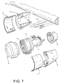
- a conventional aircraft engine such as a turbojet engine usually includes a crankcase 1, suspended from an aircraft wing 2 by a mast 3 and surrounded by a basket, so as to delimit between them an annular channel in which is placed a 4.
- the duct blower is delimited by a fan casing 5, secured to the crankcase 1 by fins (not shown)
- the nacelle In the direction of the flow of air, that is to say from before backwards, the nacelle includes successively an annular structure of air inlet 6, a pair of right and left fan covers 7, a pair of right thrust reverser covers 8 and left and an annular nozzle 9.
- the hoods of 7 are articulated on the mast 3 by their top edges and can be opened to allow maintenance. In flight, the fan cowls 7 are kept closed by locking members interposed between their lower edges.
- the internal rear edge of the structure 6 air inlet is attached directly to the front edge of the fan casing 5 by means of represented) bolts or rivets.
- each of the hoods thrust reverser 8 is also made integral the rear edge of the fan case.
- thrust reverser covers 8 are installed, this function is ensured by the interlocking of an ergot circular (not shown) in solidarity with each of thrust reverser covers 8 in a throat (no shown) machined on the fan case 5.
- this arrangement makes it possible to transmit integrally to the fan case 5 the efforts axial forces generated by the inverted thrust of the engine.
- the fan cowls 7 When the fan cowls 7 are closed, they are made integral with the structure 6. This function is usually provided by knives (not shown) mounted inside the front edge of each of the hoods of 7, who come to live without play in orifices (not shown) provided at the rear end of the air intake structure 6.
- the number of knives and orifices is a function of the size of the engine.
- the knives are sometimes replaced by a single lug formed on at least a portion of the circumference of the fan cowls 7 and coming lodge in a circumferential groove provided on the air intake structure.
- the structure air inlet 6 When the aircraft is in flight, the structure air inlet 6 is subject to differences in pressure generated by the aerodynamic flow of the air. These pressure differences have the effect of subject the air intake structure to a phenomenon of sucking, which tends to suck it forward compared to other engine components.
- the air intake structure 6 and the fan cowls 7 are made integral by knife-orifices-type structures analogous is the whole formed by the structure air intake and blower hoods that gets going in flexion and tends to be sucked forward.
- the game J2 between these parts remains constant and limited.
- the clearance J1 between the fan cowls 7 and the thrust reverser hoods 8 is accented by this flexion, because there is no connection between these hoods. This increases parasitic drag and helps to degrade fuel consumption while along the flight.
- the subject of the invention is an aircraft engine whose original design allows it to resolve at less in part the problems posed on the engines existing.
- the subject of the invention is an airplane engine in which the game between the hoods blower and thrust reverser hoods remains low when the aircraft is in flight, so as to limit parasite trauma and not to increase the fuel consumption.
- this result is obtained by means of an aircraft engine comprising a crankcase blower and a nacelle comprising successively, in the direction of the flow of air, a structure air inlet attached to the fan casing, at least a fan cowl adapted to occupy a position open and a closed position and at least one hood thrust reverser attached to the fan casing, a front edge of the blower hood being engaged on a rear edge of the air intake structure by means for transmitting axial forces, in said closed position, characterized in that means additional stiffening are placed in the air intake structure or between the hood of blower and thrust reverser hood.
- the additional means of stiffening comprise a plurality of rigid reinforcements, one of which first end is attached to the entrance structure of air, close to the means of transmission of forces axial axes, and a second end of which is attached to the air intake structure near the place where this is attached to the fan casing.
- the additional means of stiffening include complementary elements formed respectively on a front edge of the inverter cover thrust and on a rear edge of the hood of blower, said complementary elements being able to fit into each other, with a weak predetermined axial clearance, in the closed position of the fan cover, to ensure the transmission axial forces after catching said game. catching the existing game between those elements to take account of the tolerances of manufacture, this arrangement makes it possible to ensure rigid connection between the fan cowls and the thrust reverser covers, said rigid link opposing the suction force that tends to suck the air intake structure forward.
- the complementary elements comprise advantageously a plurality of orifices formed on the front edge of the thrust reverser hood and a a plurality of lugs formed on the rear edge of the hood blower, so as to penetrate into said holes in the closed position of the hood of blower, the orifices and the lugs being distributed on the periphery of the engine.
- the complementary elements may also be include a circumferential groove formed on the front edge of the thrust reverser hood and a lug formed on at least part of the circumference of the rear edge of the fan cowl, so that penetrate into said circumferential groove in the closed position of the fan cover.
- the engine according to the invention is similar to that described previously in referring to Figure 1. We will therefore refer to the description made with reference to this figure for know the main building blocks of the motor and their relative arrangement.
- the engine includes a central part delimited externally by a crankcase 1 and a nacelle surrounding the Crankcase.
- the central part of the engine is separate of the nacelle by a fan channel in which is placed a blower 4.
- a blower housing 5 surrounds the blower and is rigidly attached to the housing 1.
- the basket includes a air intake structure 6, attached to the front end of the fan casing 5, two fan cowls 7 articulated on the mast 3 and surrounding the housing of blower 5, two thrust reverser covers 8 attached to the rear end of the crankcase blower 5 and an annular nozzle 9.
- hoods of blower 7 can be tilted upwards in an open position.
- the fan cowls 7 are closed and their edges are connected to each other by means of locking.
- the air intake structure 6 includes an envelope 10, an inner envelope 12 provided with a anti noise structure 14 and stiffeners 16 connecting between them the envelopes 10 and 12, at the level of the rear end of the outer casing 10.
- each of the stiffeners 16 is attached to the envelope 10 by a square 18 and organs of fasteners such as rivets or bolts schematically by the mixed lines 20 and 22.
- each stiffeners 16 is attached to the inner casing 12 by a bracket 24 and fasteners such as rivets or bolts schematically illustrated by the mixed lines 26 and 28.
- the stiffeners 16 are arranged so such that their ends are located in the same plane substantially perpendicular to the longitudinal axis of the motor.
- the rear end of said inner envelope 12 is attached to the front end of the fan case 5, for example by brackets 30 and 32 and bodies fasteners such as rivets or bolts illustrated schematically by the mixed lines 34, 36 and 38.
- the hoods of blower 7 are made integral with the structure air intake 6 for example by knives 40 which come to stay without play in orifices 42 provided at the rear end of the air intake structure 6.
- the orifices 42 are formed in parts 44 which are attached to the rear edge of the entrance structure 6, close to the outer shell of it. This attachment can in particular be ensured by the fixing means 20 serving to fix the stiffeners 16 on the brackets 18.
- the fan cowlings 7 can also be returned integral with the air inlet structure 6 in providing a circumferential groove on the edge rear of the air intake structure 6, nearby the outer shell of the latter, and a pin on the front edge of each of the fan cowls 7, at the less on part of their circumference. When the fan cowls are closed, the pin enters without play in the circumferential groove, so as to secure said covers 7 of the input structure of air 6.
- the structure air intake 6 deforms forward, in its outside, due to differences in pressure generated by the aerodynamic flow of air when the plane is in flight.
- the fan cowls 7 are driven forward by the play-free link provided by the 40 knives and orifices 42.
- the game J2 remains constant and very weak.
- the game J1 increases, which has the effect of increasing the drag aerodynamics and, consequently, the consumption of fuel on existing engines.
- means additional stiffening are integrated into the nacelle, in order to increase very significantly the rigidity of the assembly formed by the input structure 6 and the fan cowls 7.
- these additional means of stiffening comprise a plurality of rigid reinforcements, one of which is shown at 48 in Figure 2.
- Each of the rigid reinforcements comes in the form of a bar 48 substantially rectilinear, disposed in a plane passing through the longitudinal axis of the engine.
- each of bars 48 is attached to the air inlet structure 6, proximity of axial force transmission means between said air inlet structure and the hoods of blower 7, materialized here by the knives 40 and 42.
- This fixation is ensured by brackets 50 and fastening means such as rivets or bolts, symbolized by the dotted lines 20 and 52 in Figure 2, where the bracket is fixed on the stiffener 16 by the fixing means 20 serving also to the fixing of the square 18 and the room 44.
- the first end of each of the rigid reinforcements 48 can also be fixed substantially in the middle of the length of the stiffeners 16. This arrangement makes it possible to limit the vibrations of the stiffeners in flight and, therefore, the wear of elements involved.
- each rigid reinforcements 48 is attached to the entrance structure 6, close to where said structure is attached to the fan casing 5.
- This attachment is provided by another square 54 and by means of fasteners such as rivets or bolts, symbolized by the mixed lines 34 and 56 in Figure 2, where the bracket 54 is fixed to the brackets 30 and 32 by the fixing means connecting them to one another.
- each of the rigid reinforcements 48 is shifted towards the rear and the inside of the engine compared to its first end.
- rigid reinforcements 48 connect the back of the peripheral part exterior of the air intake structure 6 at the rear of the inner peripheral part of the structure, in its fixing area on the housing of blower 5, that is to say on a rigid part of the engine.
- the rigid reinforcements 48 repeat the efforts that tend to move the party forward outer peripheral of the air intake structure 6, compared to the rest of the engine, when the plane is in flight.
- Rigid reinforcements 48 depend efforts to resume. Rigid reinforcements 48 are regularly distributed throughout the periphery of the nacelle.
- the additional means of stiffening include complementary elements 58, 60 formed respectively on the front edges of the hoods thrust reverser 8 and on the rear edges of fan hoods 7.
- these elements 58 and 60 are arranged in such a way as to fit one into the other, with low axial clearance predetermined, when the fan cowls 6 are closed.
- the presence of a small axial clearance between these complementary elements is made necessary by the manufacturing and assembly tolerances, taking into account the that the fan cowls 7 are rendered integral with the air intake structure 6 to their front ends.
- Complementary elements 58 and 60 thus ensure, in the axial direction, a rigid connection between the blower hoods 7 and the hoods thrust reverser 8, when the low axial clearance that originally existed between these elements was caught.
- fastening means 64 such as rivets or bolts.
- These additional elements also include a plurality of lugs 60, which are attached to the rear edge of each of the hoods blower 7, by fastening means 62 such that rivets or bolts, so as to penetrate the orifices 58 when the fan cowls are closed, leaving between them the aforementioned axial clearance.
- the lugs 60 are replaced by a lug unique formed on at least a part of the circumference of the trailing edge of each hood of blower and the multiple orifices 58 are replaced by a circumferential groove formed on the edge front of each thrust reverser hood.
- this second embodiment makes it possible to keep the J1 game almost constant between thrust reverser covers 8 and the assembly formed by the air inlet structure 6 and the hoods of 7. Therefore, the consumption of fuel is kept to a minimum despite the pressure differences applied in flight on the air intake structure 6, due to the flow aerodynamic air.
Landscapes
- Engineering & Computer Science (AREA)
- Aviation & Aerospace Engineering (AREA)
- Chemical & Material Sciences (AREA)
- Combustion & Propulsion (AREA)
- Mechanical Engineering (AREA)
- General Engineering & Computer Science (AREA)
- Structures Of Non-Positive Displacement Pumps (AREA)
- Turbine Rotor Nozzle Sealing (AREA)
- Automatic Cycles, And Cycles In General (AREA)
Abstract
Description
- la figure 1, déjà décrite, est une vue en perspective éclatée qui représente un moteur d'avion de l'art antérieur ;
- la figure 2 est une vue en coupe à plus grande échelle de la zone de jonction entre la structure d'entrée d'air et l'un des capots de soufflante de la nacelle d'un moteur d'avion, selon un premier mode de réalisation de l'invention ; et
- la figure 3 est une vue en coupe à plus grande échelle de la zone de jonction entre l'un des capots de soufflante et le capot d'inverseur de poussée adjacent, selon un deuxième mode de réalisation de l'invention.
Claims (6)
- Moteur d'avion comprenant un carter de soufflante (5) et une nacelle comportant successivement, dans le sens de l'écoulement de l'air, une structure d'entrée d'air (6) fixée au carter de soufflante (5), au moins un capot de soufflante (7) apte à occuper une position ouverte et une position fermée et au moins un capot (8) d'inverseur de poussée fixé au carter de soufflante (5), un bord avant du capot de soufflante (7) étant en prise sur un bord arrière de la structure d'entrée d'air (6) par des moyens (40, 42) de transmission d'efforts axiaux, dans ladite position fermée, caractérisé en ce que des moyens additionnels de rigidification (48 ; 58, 60) sont placés dans la structure d'entrée d'air (6) ou entre le capot de soufflante (7) et le capot (8) d'inverseur de poussée.
- Moteur d'avion selon la revendication 1, dans lequel les moyens additionnels de rigidification comprennent une pluralité de renforts rigides (48) dont une première extrémité est fixée à la structure d'entrée d'air (6), à proximité des moyens (40,42) de transmission d'efforts axiaux, et dont une deuxième extrémité est fixée à la structure d'entrée d'air (6) à proximité de l'endroit où celle-ci est fixée au carter de soufflante (5).
- Moteur d'avion selon la revendication 1, dans lequel la structure d'entrée d'air (6) comprend une enveloppe extérieure (10), une enveloppe intérieure (12) et des raidisseurs (16) reliant entre elles les enveloppes extérieure (10) et intérieure (12), les moyens additionnels de rigidification comprenant une pluralité de renforts rigides (48) dont une première extrémité est fixée aux raidisseurs (16), sensiblement au milieu de leur longueur, et dont une deuxième extrémité est fixée à la structure d'entrée d'air (6) à proximité de l'endroit où celle-ci est fixée au carter de soufflante (5).
- Moteur d'avion selon l'une quelconque des revendications précédentes, dans lequel les moyens additionnels de rigidification comprennent des éléments complémentaires (58, 60) formés respectivement sur un bord avant du capot (8) d'inverseur de poussée et sur un bord arrière du capot de soufflante (7), lesdits éléments complémentaires (58, 60) étant aptes à s'emboíter l'un dans l'autre, avec un faible jeu axial prédéterminé, dans la position fermée du capot de soufflante (7), pour assurer la transmission d'efforts axiaux après rattrapage dudit jeu.
- Moteur d'avion selon la revendication 4, dans lequel les éléments complémentaires comprennent une pluralité d'orifices (58) formés sur le bord avant du capot (8) d'inverseur de poussée et une pluralité d'ergots (60) formés sur le bord arrière du capot de soufflante (7), de façon à pénétrer dans lesdits orifices (58) dans la position fermée du capot de soufflante (7), les orifices (58) et les ergots (60) étant répartis sur la périphérie du moteur.
- Moteur d'avion selon la revendication 4, dans lequel les éléments complémentaires comprennent une gorge circonférentielle formée sur le bord avant du capot (8) d'inverseur de poussée et un ergot formé sur au moins une partie de la circonférence du bord arrière du capot de soufflante (7), de façon à pénétrer dans ladite gorge circonférentielle dans la position fermée du capot de soufflante (7).
Applications Claiming Priority (2)
| Application Number | Priority Date | Filing Date | Title |
|---|---|---|---|
| FR0350231 | 2003-06-18 | ||
| FR0350231A FR2856379B1 (fr) | 2003-06-18 | 2003-06-18 | Moteur d'avion dont les capots de soufflante et d'inverseurs de poussee sont separes par un jeu reduit |
Publications (2)
| Publication Number | Publication Date |
|---|---|
| EP1488999A1 true EP1488999A1 (fr) | 2004-12-22 |
| EP1488999B1 EP1488999B1 (fr) | 2006-08-16 |
Family
ID=33396881
Family Applications (1)
| Application Number | Title | Priority Date | Filing Date |
|---|---|---|---|
| EP04102758A Expired - Lifetime EP1488999B1 (fr) | 2003-06-18 | 2004-06-16 | Moteur d'avion dont les capots de soufflante et d'inverseurs de poussée sont séparés par un jeu réduit |
Country Status (7)
| Country | Link |
|---|---|
| US (1) | US7334393B2 (fr) |
| EP (1) | EP1488999B1 (fr) |
| AT (1) | ATE336421T1 (fr) |
| CA (1) | CA2470926C (fr) |
| DE (1) | DE602004001924T2 (fr) |
| ES (1) | ES2270282T3 (fr) |
| FR (1) | FR2856379B1 (fr) |
Cited By (5)
| Publication number | Priority date | Publication date | Assignee | Title |
|---|---|---|---|---|
| WO2007083024A1 (fr) | 2006-01-23 | 2007-07-26 | Aircelle | Systeme de fixation pour element constitutif d'une nacelle de turboreacteur |
| WO2008006826A1 (fr) * | 2006-07-11 | 2008-01-17 | Airbus France | Ensemble moteur pour aeronef comprenant un capotage aerodynamique de jonction monte sur deux elements distincts |
| FR2967398A1 (fr) * | 2010-11-16 | 2012-05-18 | Aircelle Sa | Structure de renforcement d'une nacelle de turboreacteur |
| FR2987601A1 (fr) * | 2012-09-20 | 2013-09-06 | Aircelle Sa | Nacelle laminaire |
| FR3148006A1 (fr) * | 2023-04-21 | 2024-10-25 | Airbus Operations (S.A.S.) | Entrée d’air d’une nacelle d’aéronef comprenant des renforts radiaux arrières disjoints, ensemble de propulsion et aéronef comprenant ladite entrée d’air |
Families Citing this family (31)
| Publication number | Priority date | Publication date | Assignee | Title |
|---|---|---|---|---|
| FR2868124B1 (fr) * | 2004-03-29 | 2006-06-23 | Airbus France Sas | Structure d'entree d'air pour moteur d'aeronef |
| US7721525B2 (en) * | 2006-07-19 | 2010-05-25 | Rohr, Inc. | Aircraft engine inlet having zone of deformation |
| US7665310B2 (en) * | 2006-12-27 | 2010-02-23 | General Electric Company | Gas turbine engine having a cooling-air nacelle-cowl duct integral with a nacelle cowl |
| FR2920136B1 (fr) * | 2007-08-20 | 2009-10-30 | Aircelle Sa | Systeme de liaison entre une structure interne et un structure externe d'une nacelle |
| FR2926791B1 (fr) * | 2008-01-29 | 2010-05-28 | Aircelle Sa | Entree d'air pour nacelle d'aeronef, et ensemble propulsif comprenant une telle entree d'air |
| GB2458679B (en) * | 2008-03-28 | 2010-04-21 | Rolls Royce Plc | Acoustic liners |
| FR2936223B1 (fr) * | 2008-09-23 | 2010-09-17 | Airbus France | Dispositif de liaison entre une entree d'air et une motorisation d'une nacelle d'aeronef |
| US7798285B2 (en) * | 2008-11-14 | 2010-09-21 | Rohr, Inc. | Acoustic barrel for aircraft engine nacelle including crack and delamination stoppers |
| US9188026B2 (en) * | 2008-11-26 | 2015-11-17 | Mra Systems, Inc. | Apparatus for facilitating access to a nacelle interior and method of assembling the same |
| US9188025B2 (en) * | 2008-11-26 | 2015-11-17 | Mra Systems, Inc. | Apparatus for facilitating access to a nacelle interior |
| US8220738B2 (en) * | 2008-11-26 | 2012-07-17 | Mra Systems, Inc. | Nacelle and method of assembling the same |
| US8197191B2 (en) * | 2009-04-14 | 2012-06-12 | Rohr, Inc. | Inlet section of an aircraft engine nacelle |
| FR2955312B1 (fr) * | 2010-01-20 | 2013-05-31 | Airbus Operations Sas | Dispositif de liaison fusible entre une partie mobile et une partie fixe d'une nacelle d'aeronef |
| FR2966128B1 (fr) * | 2010-10-15 | 2013-06-14 | Airbus Operations Sas | Nacelle d'aeronef incorporant une zone de jonction continue entre une paroi exterieure et un cadre avant et/ou un cadre arriere |
| US8752795B2 (en) * | 2010-11-23 | 2014-06-17 | John Ralph Stewart, III | Inlet nose cowl with a locally thickened fastening portion to enable an uninterrupted airflow surface |
| US9016042B2 (en) | 2011-05-20 | 2015-04-28 | Rohr, Inc. | Reinforcement members for aircraft propulsion system components configured to address delamination of the inner fixed structure |
| FR2986582B1 (fr) * | 2012-02-06 | 2014-03-14 | Snecma | Carter de soufflante pour moteur a turbine a gaz munie d'une bride pour la fixation d'equipements |
| US9555871B2 (en) * | 2012-03-05 | 2017-01-31 | The Boeing Company | Two-surface sandwich structure for accommodating in-plane expansion of one of the surfaces relative to the opposing surface |
| US9833930B2 (en) | 2012-10-23 | 2017-12-05 | Albany Engineered Composites, Inc. | Circumferential stiffeners for composite fancases |
| FR2998545B1 (fr) * | 2012-11-23 | 2016-10-28 | Airbus Operations Sas | Nacelle d'aeronef comprenant une liaison renforcee entre une entree d'air et une motorisation |
| FR2998548B1 (fr) * | 2012-11-23 | 2015-01-30 | Airbus Operations Sas | Nacelle d'aeronef comprenant une liaison renforcee entre une entree d'air et une motorisation |
| FR3075759B1 (fr) * | 2017-12-21 | 2020-11-06 | Airbus Operations Sas | Partie anterieure de nacelle d'un ensemble propulsif d'aeronef comportant un element amortisseur |
| GB201809822D0 (en) * | 2018-06-15 | 2018-08-01 | Rolls Royce Plc | Gas turbine engine |
| FR3095418B1 (fr) * | 2019-04-26 | 2021-09-24 | Safran Nacelles | Entrée d’air de nacelle et nacelle comportant une telle entrée d’air |
| FR3095417B1 (fr) * | 2019-04-26 | 2021-09-24 | Safran Nacelles | Entrée d’air de nacelle et nacelle comportant une telle entrée d’air |
| US11414200B2 (en) * | 2019-04-29 | 2022-08-16 | Rohr, Inc. | Fan cowl securement retainers |
| CN110466782B (zh) * | 2019-07-26 | 2022-12-20 | 中国航发沈阳发动机研究所 | 一种航空发动机用弹性连接组件 |
| CN111977026B (zh) * | 2020-07-29 | 2022-11-22 | 西安飞机工业(集团)有限责任公司 | 一种飞机进气道圆形开口的检测方法 |
| US11878808B2 (en) * | 2022-04-05 | 2024-01-23 | Rohr, Inc. | Nacelle inlet structure fitting with locator clip and hoist bracket |
| EP4470920A1 (fr) * | 2023-05-29 | 2024-12-04 | Airbus Operations (S.A.S.) | Ensemble de propulsion d'aéronef comportant au moins un panneau aérodynamique supporté par au moins un support radial intermédiaire, aéronef comprenant au moins un tel ensemble de propulsion |
| FR3151837A1 (fr) * | 2023-08-01 | 2025-02-07 | Airbus Operations | Ensemble de positionnement ameliore de capot mobile d’aeronef et aeronef muni d’un tel ensemble. |
Citations (5)
| Publication number | Priority date | Publication date | Assignee | Title |
|---|---|---|---|---|
| EP0744339A1 (fr) * | 1995-05-24 | 1996-11-27 | AEROSPATIALE Société Nationale Industrielle | Nacelle de moteur d'aéronef comportant un capot de nacelle |
| US5603471A (en) * | 1991-09-27 | 1997-02-18 | Short Brothers Plc | Ducted fan turbine engine nozzle assembly |
| EP0898063A1 (fr) * | 1997-08-19 | 1999-02-24 | AEROSPATIALE Société Nationale Industrielle | Ensemble réducteur de bruit pour turboréacteur d'aéronef |
| WO1999030969A1 (fr) * | 1997-12-16 | 1999-06-24 | Aerospatiale Societe Nationale Industrielle | Ensemble propulseur a capots de soufflante munis de securites de maintien et de positionnement, pour aeronef |
| US6340135B1 (en) * | 2000-05-30 | 2002-01-22 | Rohr, Inc. | Translating independently mounted air inlet system for aircraft turbofan jet engine |
Family Cites Families (19)
| Publication number | Priority date | Publication date | Assignee | Title |
|---|---|---|---|---|
| US4044973A (en) * | 1975-12-29 | 1977-08-30 | The Boeing Company | Nacelle assembly and mounting structures for a turbofan jet propulsion engine |
| US4150802A (en) * | 1977-05-31 | 1979-04-24 | The Boeing Company | Aircraft engine installation |
| GB2093125B (en) * | 1981-02-14 | 1984-04-18 | Rolls Royce | Gas turbine engine casing |
| US4603821A (en) * | 1983-12-30 | 1986-08-05 | The Boeing Company | System for mounting a jet engine |
| FR2560854B1 (fr) * | 1984-03-07 | 1986-09-12 | Snecma | Capotages structuraux participant a la rigidite d'ensemble d'un turboreacteur |
| FR2622507B1 (fr) * | 1987-10-28 | 1990-01-26 | Snecma | |
| GB8822798D0 (en) * | 1988-09-28 | 1988-11-02 | Short Brothers Ltd | Ducted fan turbine engine |
| FR2645911B1 (fr) * | 1989-04-18 | 1991-06-07 | Snecma | Moteur a grand taux de dilution a soufflante amont et soufflante aval |
| FR2661213B1 (fr) * | 1990-04-19 | 1992-07-03 | Snecma | Moteur d'aviation a tres grand taux de dilution et du type dit contrafan avant. |
| US5174525A (en) * | 1991-09-26 | 1992-12-29 | General Electric Company | Structure for eliminating lift load bending in engine core of turbofan |
| US5205513A (en) * | 1991-09-26 | 1993-04-27 | General Electric Company | Method and system for the removal of large turbine engines |
| US5524847A (en) * | 1993-09-07 | 1996-06-11 | United Technologies Corporation | Nacelle and mounting arrangement for an aircraft engine |
| FR2732074B1 (fr) * | 1995-03-21 | 1997-06-06 | Aerospatiale | Turboreacteur a double flux a nacelle flottante |
| FR2771451B1 (fr) * | 1997-11-21 | 2000-04-14 | Aerospatiale | Dispositif de protection pour capot d'entree d'air de moteur a reaction, pourvu d'un systeme de degivrage |
| FR2771459B1 (fr) * | 1997-11-27 | 2000-02-04 | Aerospatiale | Bielle telescopique d'ouverture d'un capot mobile, notamment de nacelle d'un moteur d'avion |
| FR2793768B1 (fr) * | 1999-05-17 | 2001-09-07 | Aerospatiale Airbus | Dispositif de montage sur un mat d'un ensemble propulsif d'aeronef et mat adapte a ce dispositif |
| FR2813581B1 (fr) * | 2000-09-06 | 2002-11-29 | Aerospatiale Matra Airbus | Capot d'entree d'air de moteur a reaction pourvu de moyens de degivrage |
| FR2823533B1 (fr) * | 2001-04-17 | 2003-08-08 | Eads Airbus Sa | Capot d'entree d'air pour moteur a reaction, pourvu de moyens de degivrage |
| FR2840647B1 (fr) * | 2002-06-05 | 2004-10-29 | Airbus France | Dispositif pour le raccordement de deux pieces tubulaires de turboreacteur d'aeronef |
-
2003
- 2003-06-18 FR FR0350231A patent/FR2856379B1/fr not_active Expired - Fee Related
-
2004
- 2004-04-12 US US10/821,854 patent/US7334393B2/en not_active Expired - Lifetime
- 2004-06-15 CA CA2470926A patent/CA2470926C/fr not_active Expired - Lifetime
- 2004-06-16 DE DE602004001924T patent/DE602004001924T2/de not_active Expired - Lifetime
- 2004-06-16 EP EP04102758A patent/EP1488999B1/fr not_active Expired - Lifetime
- 2004-06-16 ES ES04102758T patent/ES2270282T3/es not_active Expired - Lifetime
- 2004-06-16 AT AT04102758T patent/ATE336421T1/de not_active IP Right Cessation
Patent Citations (5)
| Publication number | Priority date | Publication date | Assignee | Title |
|---|---|---|---|---|
| US5603471A (en) * | 1991-09-27 | 1997-02-18 | Short Brothers Plc | Ducted fan turbine engine nozzle assembly |
| EP0744339A1 (fr) * | 1995-05-24 | 1996-11-27 | AEROSPATIALE Société Nationale Industrielle | Nacelle de moteur d'aéronef comportant un capot de nacelle |
| EP0898063A1 (fr) * | 1997-08-19 | 1999-02-24 | AEROSPATIALE Société Nationale Industrielle | Ensemble réducteur de bruit pour turboréacteur d'aéronef |
| WO1999030969A1 (fr) * | 1997-12-16 | 1999-06-24 | Aerospatiale Societe Nationale Industrielle | Ensemble propulseur a capots de soufflante munis de securites de maintien et de positionnement, pour aeronef |
| US6340135B1 (en) * | 2000-05-30 | 2002-01-22 | Rohr, Inc. | Translating independently mounted air inlet system for aircraft turbofan jet engine |
Cited By (15)
| Publication number | Priority date | Publication date | Assignee | Title |
|---|---|---|---|---|
| RU2433071C2 (ru) * | 2006-01-23 | 2011-11-10 | Эрсель | Система крепления составного элемента гондолы турбореактивного двигателя |
| FR2896481A1 (fr) * | 2006-01-23 | 2007-07-27 | Aircelle Sa | Systeme de fixation pour element constitutif d'une nacelle de turboreacteur |
| CN101360649B (zh) * | 2006-01-23 | 2013-03-27 | 埃尔塞乐公司 | 用于涡轮喷气发动机的发动机罩的部件的固定系统 |
| WO2007083024A1 (fr) | 2006-01-23 | 2007-07-26 | Aircelle | Systeme de fixation pour element constitutif d'une nacelle de turboreacteur |
| RU2433070C2 (ru) * | 2006-07-11 | 2011-11-10 | Эрбюс Франс | Силовая установка летательного аппарата, содержащая соединительный аэродинамический обтекатель, смонтированный на двух отдельных элементах |
| CN101484359B (zh) * | 2006-07-11 | 2011-05-11 | 法国空中客车公司 | 包括安装在两个不同部件上的接口空气动力学整流罩的用于飞行器的发动机组件 |
| FR2903666A1 (fr) * | 2006-07-11 | 2008-01-18 | Airbus France Sas | Ensemble moteur pour aeronef comprenant un capotage aerodynamique de jonction monte sur deux elements distincts |
| US8162254B2 (en) | 2006-07-11 | 2012-04-24 | Airbus Operations Sas | Aircraft engine assembly comprising a junction aerodynamic fairing mounted on two separate elements |
| WO2008006826A1 (fr) * | 2006-07-11 | 2008-01-17 | Airbus France | Ensemble moteur pour aeronef comprenant un capotage aerodynamique de jonction monte sur deux elements distincts |
| FR2967398A1 (fr) * | 2010-11-16 | 2012-05-18 | Aircelle Sa | Structure de renforcement d'une nacelle de turboreacteur |
| WO2012066211A1 (fr) * | 2010-11-16 | 2012-05-24 | Aircelle | Structure de renforcement d'une nacelle de turboréacteur |
| RU2569725C2 (ru) * | 2010-11-16 | 2015-11-27 | Эрсель | Усиливающая конструкция гондолы турбореактивного двигателя |
| US10087842B2 (en) | 2010-11-16 | 2018-10-02 | Aircelle | Turbojet engine nacelle reinforcing structure |
| FR2987601A1 (fr) * | 2012-09-20 | 2013-09-06 | Aircelle Sa | Nacelle laminaire |
| FR3148006A1 (fr) * | 2023-04-21 | 2024-10-25 | Airbus Operations (S.A.S.) | Entrée d’air d’une nacelle d’aéronef comprenant des renforts radiaux arrières disjoints, ensemble de propulsion et aéronef comprenant ladite entrée d’air |
Also Published As
| Publication number | Publication date |
|---|---|
| CA2470926A1 (fr) | 2004-12-18 |
| US20040255572A1 (en) | 2004-12-23 |
| EP1488999B1 (fr) | 2006-08-16 |
| US7334393B2 (en) | 2008-02-26 |
| FR2856379B1 (fr) | 2006-11-24 |
| DE602004001924D1 (de) | 2006-09-28 |
| ES2270282T3 (es) | 2007-04-01 |
| ATE336421T1 (de) | 2006-09-15 |
| FR2856379A1 (fr) | 2004-12-24 |
| DE602004001924T2 (de) | 2007-03-15 |
| CA2470926C (fr) | 2012-06-05 |
Similar Documents
| Publication | Publication Date | Title |
|---|---|---|
| EP1488999B1 (fr) | Moteur d'avion dont les capots de soufflante et d'inverseurs de poussée sont séparés par un jeu réduit | |
| EP2038175B1 (fr) | Ensemble moteur pour aeronef comprenant un berceau de support de capot de soufflante monte sur deux elements distincts | |
| EP2185413B1 (fr) | Berceau de support de capot de soufflante monte sur le mât d'accrochage et sur l'entree d'air de la nacelle | |
| EP2038176B1 (fr) | Ensemble moteur pour aeronef comprenant un capotage aerodynamique de jonction monte sur deux elements distincts | |
| EP1902951B1 (fr) | Système propulsif à pylone intégré pour avion | |
| EP1582702B1 (fr) | Structure d'entrée d'air pour moteur d'aéronef | |
| EP0960051B1 (fr) | Ensemble propulseur a capots de soufflante munis de securites de maintien et de positionnement, pour aeronef | |
| EP0527672B1 (fr) | Structure d'accrochage arrière d'un turboréacteur | |
| EP2554478B1 (fr) | Berceau d'articulation de capots de soufflante supportes par ces capots en position fermée | |
| FR2793768A1 (fr) | Dispositif de montage sur un mat d'un ensemble propulsif d'aeronef et mat adapte a ce dispositif | |
| WO2018233860A1 (fr) | Ensemble de motorisation pour un aeronef | |
| EP2072396B1 (fr) | Carter intermediaire pour turboréacteur d'aéronef à conception ameliorée | |
| FR2905991A1 (fr) | Systeme propulsif integre comportant un moteur a turboreacteur a double flux. | |
| EP0728934A1 (fr) | Inverseur de pousée à volets aval pour turboréacteur | |
| FR2610592A1 (fr) | Combinaison d'avion et de groupe motopropulseur | |
| FR3133377A1 (fr) | Ensemble de motorisation pour un aéronef comprenant un support de charge | |
| FR2966125A1 (fr) | Ensemble d'accrochage d'une suspension d'un ensemble propulsif d'aeronef | |
| EP1813529B1 (fr) | Entrée d'air de turboréacteur à double flux | |
| EP1883580B1 (fr) | Ensemble moteur pour aeronef | |
| EP3539878B1 (fr) | Turboreacteur comportant une nacelle equipee d'un carter de soufflante et d'une structure fixe | |
| FR2898336A1 (fr) | Carenage aerodynamique destine a etre rapporte fixement sous une aile d'aeronef | |
| FR3096352A1 (fr) | Ensemble de motorisation pour un aeronef comprenant un support de charge | |
| EP4237334B1 (fr) | Nacelle pour ensemble propulsif d'aéronef, comprenant une bielle de sécurité formant renfort structural | |
| WO2019243117A1 (fr) | Système propulsif arrière pour aéronef | |
| WO2017216463A1 (fr) | Ensemble propulsif pour aéronef à traînée aérodynamique réduite |
Legal Events
| Date | Code | Title | Description |
|---|---|---|---|
| PUAI | Public reference made under article 153(3) epc to a published international application that has entered the european phase |
Free format text: ORIGINAL CODE: 0009012 |
|
| AK | Designated contracting states |
Kind code of ref document: A1 Designated state(s): AT BE BG CH CY CZ DE DK EE ES FI FR GB GR HU IE IT LI LU MC NL PL PT RO SE SI SK TR |
|
| AX | Request for extension of the european patent |
Extension state: AL HR LT LV MK |
|
| 17P | Request for examination filed |
Effective date: 20050131 |
|
| 17Q | First examination report despatched |
Effective date: 20050401 |
|
| AKX | Designation fees paid |
Designated state(s): AT BE BG CH CY CZ DE DK EE ES FI FR GB GR HU IE IT LI LU MC NL PL PT RO SE SI SK TR |
|
| GRAP | Despatch of communication of intention to grant a patent |
Free format text: ORIGINAL CODE: EPIDOSNIGR1 |
|
| GRAS | Grant fee paid |
Free format text: ORIGINAL CODE: EPIDOSNIGR3 |
|
| GRAA | (expected) grant |
Free format text: ORIGINAL CODE: 0009210 |
|
| AK | Designated contracting states |
Kind code of ref document: B1 Designated state(s): AT BE BG CH CY CZ DE DK EE ES FI FR GB GR HU IE IT LI LU MC NL PL PT RO SE SI SK TR |
|
| PG25 | Lapsed in a contracting state [announced via postgrant information from national office to epo] |
Ref country code: IT Free format text: LAPSE BECAUSE OF FAILURE TO SUBMIT A TRANSLATION OF THE DESCRIPTION OR TO PAY THE FEE WITHIN THE PRESCRIBED TIME-LIMIT;WARNING: LAPSES OF ITALIAN PATENTS WITH EFFECTIVE DATE BEFORE 2007 MAY HAVE OCCURRED AT ANY TIME BEFORE 2007. THE CORRECT EFFECTIVE DATE MAY BE DIFFERENT FROM THE ONE RECORDED. Effective date: 20060816 Ref country code: SK Free format text: LAPSE BECAUSE OF FAILURE TO SUBMIT A TRANSLATION OF THE DESCRIPTION OR TO PAY THE FEE WITHIN THE PRESCRIBED TIME-LIMIT Effective date: 20060816 Ref country code: AT Free format text: LAPSE BECAUSE OF FAILURE TO SUBMIT A TRANSLATION OF THE DESCRIPTION OR TO PAY THE FEE WITHIN THE PRESCRIBED TIME-LIMIT Effective date: 20060816 Ref country code: FI Free format text: LAPSE BECAUSE OF FAILURE TO SUBMIT A TRANSLATION OF THE DESCRIPTION OR TO PAY THE FEE WITHIN THE PRESCRIBED TIME-LIMIT Effective date: 20060816 Ref country code: RO Free format text: LAPSE BECAUSE OF FAILURE TO SUBMIT A TRANSLATION OF THE DESCRIPTION OR TO PAY THE FEE WITHIN THE PRESCRIBED TIME-LIMIT Effective date: 20060816 Ref country code: CZ Free format text: LAPSE BECAUSE OF FAILURE TO SUBMIT A TRANSLATION OF THE DESCRIPTION OR TO PAY THE FEE WITHIN THE PRESCRIBED TIME-LIMIT Effective date: 20060816 Ref country code: SI Free format text: LAPSE BECAUSE OF FAILURE TO SUBMIT A TRANSLATION OF THE DESCRIPTION OR TO PAY THE FEE WITHIN THE PRESCRIBED TIME-LIMIT Effective date: 20060816 Ref country code: PL Free format text: LAPSE BECAUSE OF FAILURE TO SUBMIT A TRANSLATION OF THE DESCRIPTION OR TO PAY THE FEE WITHIN THE PRESCRIBED TIME-LIMIT Effective date: 20060816 Ref country code: NL Free format text: LAPSE BECAUSE OF FAILURE TO SUBMIT A TRANSLATION OF THE DESCRIPTION OR TO PAY THE FEE WITHIN THE PRESCRIBED TIME-LIMIT Effective date: 20060816 Ref country code: IE Free format text: LAPSE BECAUSE OF FAILURE TO SUBMIT A TRANSLATION OF THE DESCRIPTION OR TO PAY THE FEE WITHIN THE PRESCRIBED TIME-LIMIT Effective date: 20060816 |
|
| REG | Reference to a national code |
Ref country code: GB Ref legal event code: FG4D Free format text: NOT ENGLISH |
|
| REG | Reference to a national code |
Ref country code: CH Ref legal event code: EP |
|
| REG | Reference to a national code |
Ref country code: IE Ref legal event code: FG4D Free format text: LANGUAGE OF EP DOCUMENT: FRENCH |
|
| REF | Corresponds to: |
Ref document number: 602004001924 Country of ref document: DE Date of ref document: 20060928 Kind code of ref document: P |
|
| PG25 | Lapsed in a contracting state [announced via postgrant information from national office to epo] |
Ref country code: BG Free format text: LAPSE BECAUSE OF FAILURE TO SUBMIT A TRANSLATION OF THE DESCRIPTION OR TO PAY THE FEE WITHIN THE PRESCRIBED TIME-LIMIT Effective date: 20061116 Ref country code: DK Free format text: LAPSE BECAUSE OF FAILURE TO SUBMIT A TRANSLATION OF THE DESCRIPTION OR TO PAY THE FEE WITHIN THE PRESCRIBED TIME-LIMIT Effective date: 20061116 |
|
| REG | Reference to a national code |
Ref country code: SE Ref legal event code: TRGR |
|
| GBT | Gb: translation of ep patent filed (gb section 77(6)(a)/1977) |
Effective date: 20061122 |
|
| PG25 | Lapsed in a contracting state [announced via postgrant information from national office to epo] |
Ref country code: PT Free format text: LAPSE BECAUSE OF FAILURE TO SUBMIT A TRANSLATION OF THE DESCRIPTION OR TO PAY THE FEE WITHIN THE PRESCRIBED TIME-LIMIT Effective date: 20070116 |
|
| NLV1 | Nl: lapsed or annulled due to failure to fulfill the requirements of art. 29p and 29m of the patents act | ||
| REG | Reference to a national code |
Ref country code: IE Ref legal event code: FD4D |
|
| REG | Reference to a national code |
Ref country code: ES Ref legal event code: FG2A Ref document number: 2270282 Country of ref document: ES Kind code of ref document: T3 |
|
| PLBE | No opposition filed within time limit |
Free format text: ORIGINAL CODE: 0009261 |
|
| STAA | Information on the status of an ep patent application or granted ep patent |
Free format text: STATUS: NO OPPOSITION FILED WITHIN TIME LIMIT |
|
| 26N | No opposition filed |
Effective date: 20070518 |
|
| BERE | Be: lapsed |
Owner name: AIRBUS FRANCE Effective date: 20070630 |
|
| PG25 | Lapsed in a contracting state [announced via postgrant information from national office to epo] |
Ref country code: MC Free format text: LAPSE BECAUSE OF NON-PAYMENT OF DUE FEES Effective date: 20070630 |
|
| PG25 | Lapsed in a contracting state [announced via postgrant information from national office to epo] |
Ref country code: BE Free format text: LAPSE BECAUSE OF NON-PAYMENT OF DUE FEES Effective date: 20070630 |
|
| PG25 | Lapsed in a contracting state [announced via postgrant information from national office to epo] |
Ref country code: GR Free format text: LAPSE BECAUSE OF FAILURE TO SUBMIT A TRANSLATION OF THE DESCRIPTION OR TO PAY THE FEE WITHIN THE PRESCRIBED TIME-LIMIT Effective date: 20061117 |
|
| PG25 | Lapsed in a contracting state [announced via postgrant information from national office to epo] |
Ref country code: EE Free format text: LAPSE BECAUSE OF FAILURE TO SUBMIT A TRANSLATION OF THE DESCRIPTION OR TO PAY THE FEE WITHIN THE PRESCRIBED TIME-LIMIT Effective date: 20060816 |
|
| PGRI | Patent reinstated in contracting state [announced from national office to epo] |
Ref country code: IT Effective date: 20080801 |
|
| REG | Reference to a national code |
Ref country code: CH Ref legal event code: PL |
|
| PG25 | Lapsed in a contracting state [announced via postgrant information from national office to epo] |
Ref country code: LI Free format text: LAPSE BECAUSE OF NON-PAYMENT OF DUE FEES Effective date: 20080630 Ref country code: CH Free format text: LAPSE BECAUSE OF NON-PAYMENT OF DUE FEES Effective date: 20080630 |
|
| PG25 | Lapsed in a contracting state [announced via postgrant information from national office to epo] |
Ref country code: CY Free format text: LAPSE BECAUSE OF FAILURE TO SUBMIT A TRANSLATION OF THE DESCRIPTION OR TO PAY THE FEE WITHIN THE PRESCRIBED TIME-LIMIT Effective date: 20060816 Ref country code: LU Free format text: LAPSE BECAUSE OF NON-PAYMENT OF DUE FEES Effective date: 20070616 |
|
| PGFP | Annual fee paid to national office [announced via postgrant information from national office to epo] |
Ref country code: SE Payment date: 20090612 Year of fee payment: 6 |
|
| PG25 | Lapsed in a contracting state [announced via postgrant information from national office to epo] |
Ref country code: HU Free format text: LAPSE BECAUSE OF FAILURE TO SUBMIT A TRANSLATION OF THE DESCRIPTION OR TO PAY THE FEE WITHIN THE PRESCRIBED TIME-LIMIT Effective date: 20070217 Ref country code: TR Free format text: LAPSE BECAUSE OF FAILURE TO SUBMIT A TRANSLATION OF THE DESCRIPTION OR TO PAY THE FEE WITHIN THE PRESCRIBED TIME-LIMIT Effective date: 20060816 |
|
| EUG | Se: european patent has lapsed | ||
| REG | Reference to a national code |
Ref country code: GB Ref legal event code: 732E Free format text: REGISTERED BETWEEN 20110721 AND 20110727 |
|
| REG | Reference to a national code |
Ref country code: FR Ref legal event code: TP Owner name: AIRBUS HOLDING, FR Effective date: 20110913 Ref country code: FR Ref legal event code: CJ Effective date: 20110916 Ref country code: FR Ref legal event code: CD Owner name: AIRBUS HOLDING, FR Effective date: 20110916 Ref country code: FR Ref legal event code: CA Effective date: 20110916 |
|
| REG | Reference to a national code |
Ref country code: ES Ref legal event code: PC2A Owner name: AIRBUS OPERATIONS SAS Effective date: 20120308 |
|
| REG | Reference to a national code |
Ref country code: DE Ref legal event code: R082 Ref document number: 602004001924 Country of ref document: DE Representative=s name: HENKEL, BREUER & PARTNER, DE |
|
| REG | Reference to a national code |
Ref country code: DE Ref legal event code: R081 Ref document number: 602004001924 Country of ref document: DE Owner name: AIRBUS OPERATIONS SAS, FR Free format text: FORMER OWNER: AIRBUS FRANCE, TOULOUSE, FR Effective date: 20120326 Ref country code: DE Ref legal event code: R082 Ref document number: 602004001924 Country of ref document: DE Representative=s name: PATENTANWAELTE HENKEL, BREUER & PARTNER, DE Effective date: 20120326 Ref country code: DE Ref legal event code: R082 Ref document number: 602004001924 Country of ref document: DE Representative=s name: PATENTANWAELTE HENKEL, BREUER & PARTNER MBB, DE Effective date: 20120326 |
|
| PG25 | Lapsed in a contracting state [announced via postgrant information from national office to epo] |
Ref country code: SE Free format text: LAPSE BECAUSE OF NON-PAYMENT OF DUE FEES Effective date: 20100617 |
|
| REG | Reference to a national code |
Ref country code: FR Ref legal event code: PLFP Year of fee payment: 13 |
|
| REG | Reference to a national code |
Ref country code: FR Ref legal event code: PLFP Year of fee payment: 14 |
|
| PGFP | Annual fee paid to national office [announced via postgrant information from national office to epo] |
Ref country code: IT Payment date: 20170622 Year of fee payment: 14 |
|
| PGFP | Annual fee paid to national office [announced via postgrant information from national office to epo] |
Ref country code: ES Payment date: 20170725 Year of fee payment: 14 |
|
| REG | Reference to a national code |
Ref country code: FR Ref legal event code: PLFP Year of fee payment: 15 |
|
| PG25 | Lapsed in a contracting state [announced via postgrant information from national office to epo] |
Ref country code: IT Free format text: LAPSE BECAUSE OF FAILURE TO SUBMIT A TRANSLATION OF THE DESCRIPTION OR TO PAY THE FEE WITHIN THE PRESCRIBED TIME-LIMIT Effective date: 20180616 |
|
| REG | Reference to a national code |
Ref country code: ES Ref legal event code: FD2A Effective date: 20190916 |
|
| PG25 | Lapsed in a contracting state [announced via postgrant information from national office to epo] |
Ref country code: ES Free format text: LAPSE BECAUSE OF NON-PAYMENT OF DUE FEES Effective date: 20180617 |
|
| PGFP | Annual fee paid to national office [announced via postgrant information from national office to epo] |
Ref country code: DE Payment date: 20200618 Year of fee payment: 17 |
|
| REG | Reference to a national code |
Ref country code: DE Ref legal event code: R119 Ref document number: 602004001924 Country of ref document: DE |
|
| PG25 | Lapsed in a contracting state [announced via postgrant information from national office to epo] |
Ref country code: DE Free format text: LAPSE BECAUSE OF NON-PAYMENT OF DUE FEES Effective date: 20220101 |
|
| PGFP | Annual fee paid to national office [announced via postgrant information from national office to epo] |
Ref country code: FR Payment date: 20230622 Year of fee payment: 20 |
|
| PGFP | Annual fee paid to national office [announced via postgrant information from national office to epo] |
Ref country code: GB Payment date: 20230620 Year of fee payment: 20 |
|
| PG25 | Lapsed in a contracting state [announced via postgrant information from national office to epo] |
Ref country code: GB Free format text: LAPSE BECAUSE OF EXPIRATION OF PROTECTION Effective date: 20240615 |
|
| PG25 | Lapsed in a contracting state [announced via postgrant information from national office to epo] |
Ref country code: GB Free format text: LAPSE BECAUSE OF EXPIRATION OF PROTECTION Effective date: 20240615 |