EP1488975A1 - Damping device for a hydraulic unit - Google Patents
Damping device for a hydraulic unit Download PDFInfo
- Publication number
- EP1488975A1 EP1488975A1 EP04102197A EP04102197A EP1488975A1 EP 1488975 A1 EP1488975 A1 EP 1488975A1 EP 04102197 A EP04102197 A EP 04102197A EP 04102197 A EP04102197 A EP 04102197A EP 1488975 A1 EP1488975 A1 EP 1488975A1
- Authority
- EP
- European Patent Office
- Prior art keywords
- elastic element
- hydraulic unit
- damping
- vibrations
- elastic
- Prior art date
- Legal status (The legal status is an assumption and is not a legal conclusion. Google has not performed a legal analysis and makes no representation as to the accuracy of the status listed.)
- Granted
Links
Images

Classifications
-
- F—MECHANICAL ENGINEERING; LIGHTING; HEATING; WEAPONS; BLASTING
- F04—POSITIVE - DISPLACEMENT MACHINES FOR LIQUIDS; PUMPS FOR LIQUIDS OR ELASTIC FLUIDS
- F04B—POSITIVE-DISPLACEMENT MACHINES FOR LIQUIDS; PUMPS
- F04B53/00—Component parts, details or accessories not provided for in, or of interest apart from, groups F04B1/00 - F04B23/00 or F04B39/00 - F04B47/00
- F04B53/001—Noise damping
- F04B53/003—Noise damping by damping supports
-
- B—PERFORMING OPERATIONS; TRANSPORTING
- B60—VEHICLES IN GENERAL
- B60T—VEHICLE BRAKE CONTROL SYSTEMS OR PARTS THEREOF; BRAKE CONTROL SYSTEMS OR PARTS THEREOF, IN GENERAL; ARRANGEMENT OF BRAKING ELEMENTS ON VEHICLES IN GENERAL; PORTABLE DEVICES FOR PREVENTING UNWANTED MOVEMENT OF VEHICLES; VEHICLE MODIFICATIONS TO FACILITATE COOLING OF BRAKES
- B60T8/00—Arrangements for adjusting wheel-braking force to meet varying vehicular or ground-surface conditions, e.g. limiting or varying distribution of braking force
- B60T8/32—Arrangements for adjusting wheel-braking force to meet varying vehicular or ground-surface conditions, e.g. limiting or varying distribution of braking force responsive to a speed condition, e.g. acceleration or deceleration
- B60T8/34—Arrangements for adjusting wheel-braking force to meet varying vehicular or ground-surface conditions, e.g. limiting or varying distribution of braking force responsive to a speed condition, e.g. acceleration or deceleration having a fluid pressure regulator responsive to a speed condition
- B60T8/36—Arrangements for adjusting wheel-braking force to meet varying vehicular or ground-surface conditions, e.g. limiting or varying distribution of braking force responsive to a speed condition, e.g. acceleration or deceleration having a fluid pressure regulator responsive to a speed condition including a pilot valve responding to an electromagnetic force
- B60T8/3615—Electromagnetic valves specially adapted for anti-lock brake and traction control systems
- B60T8/3675—Electromagnetic valves specially adapted for anti-lock brake and traction control systems integrated in modulator units
- B60T8/368—Electromagnetic valves specially adapted for anti-lock brake and traction control systems integrated in modulator units combined with other mechanical components, e.g. pump units, master cylinders
- B60T8/3685—Electromagnetic valves specially adapted for anti-lock brake and traction control systems integrated in modulator units combined with other mechanical components, e.g. pump units, master cylinders characterised by the mounting of the modulator unit onto the vehicle
-
- F—MECHANICAL ENGINEERING; LIGHTING; HEATING; WEAPONS; BLASTING
- F04—POSITIVE - DISPLACEMENT MACHINES FOR LIQUIDS; PUMPS FOR LIQUIDS OR ELASTIC FLUIDS
- F04B—POSITIVE-DISPLACEMENT MACHINES FOR LIQUIDS; PUMPS
- F04B39/00—Component parts, details, or accessories, of pumps or pumping systems specially adapted for elastic fluids, not otherwise provided for in, or of interest apart from, groups F04B25/00 - F04B37/00
- F04B39/0027—Pulsation and noise damping means
- F04B39/0044—Pulsation and noise damping means with vibration damping supports
-
- F—MECHANICAL ENGINEERING; LIGHTING; HEATING; WEAPONS; BLASTING
- F04—POSITIVE - DISPLACEMENT MACHINES FOR LIQUIDS; PUMPS FOR LIQUIDS OR ELASTIC FLUIDS
- F04B—POSITIVE-DISPLACEMENT MACHINES FOR LIQUIDS; PUMPS
- F04B53/00—Component parts, details or accessories not provided for in, or of interest apart from, groups F04B1/00 - F04B23/00 or F04B39/00 - F04B47/00
- F04B53/16—Casings; Cylinders; Cylinder liners or heads; Fluid connections
-
- F—MECHANICAL ENGINEERING; LIGHTING; HEATING; WEAPONS; BLASTING
- F16—ENGINEERING ELEMENTS AND UNITS; GENERAL MEASURES FOR PRODUCING AND MAINTAINING EFFECTIVE FUNCTIONING OF MACHINES OR INSTALLATIONS; THERMAL INSULATION IN GENERAL
- F16L—PIPES; JOINTS OR FITTINGS FOR PIPES; SUPPORTS FOR PIPES, CABLES OR PROTECTIVE TUBING; MEANS FOR THERMAL INSULATION IN GENERAL
- F16L55/00—Devices or appurtenances for use in, or in connection with, pipes or pipe systems
- F16L55/02—Energy absorbers; Noise absorbers
- F16L55/033—Noise absorbers
- F16L55/035—Noise absorbers in the form of specially adapted hangers or supports
Definitions
- the present invention relates to a device for Damping vibrations for a hydraulic unit.
- Hydraulic units are used in motor vehicles for example in braking systems, stability systems or Traction systems used.
- the hydraulic units are in usually compact components, which a pump, a electrical actuator, valves, etc. include.
- Vibrations and structure-borne noise which, for example, over a bracket with which the hydraulic unit on Vehicle is attached to other components of the vehicle is transmitted.
- a structure-borne noise which however other vehicle components is transmitted turns out to be Noise, both inside and outside the vehicle noticeable.
- the structure-borne noise can also be heard on the Hydraulic unit existing connections and lines be transmitted. Because in today's vehicles Noise requirements always become larger, in particular a transfer of the Structure-borne noise in the vehicle interior can be prevented to avoid a negative impression among users of the Vehicle.
- the inventive device for damping Vibrations for a hydraulic unit with the Features of claim 1, however, has the Advantage that by means of an elastic element Damping vibrations of the hydraulic unit, in particular damping structure-borne noise becomes.
- the elastic element is on one Pipe connection element of the hydraulic unit arranged.
- a bracket for attaching the hydraulic unit on the vehicle is on attached elastic element.
- the elastic elements By arranging the elastic elements on the Line connection elements can be the least possible Space required for the elastic elements become.
- the elastic elements take over at the same time vibration damping for the hydraulic Line connections and lines etc. as well as for that entire hydraulic unit because the bracket on the elastic elements is arranged.
- a separate elastic element is arranged at each line connection.
- a common elastic element provided, which dampens vibrations at every line connection. This is a small number of components is necessary. Furthermore can thereby the best possible damping of the vibrations can be achieved, since the vibrations also over the common elastic element can cancel each other.
- the elastic Element preferably surrounded by an inelastic band.
- the inelastic band is, for example, made of metal or Made of plastic.
- the elastic Element preferably a circumferential, groove-shaped recess to take up the inelastic tape.
- elastic Element In order to influence the damping behavior of the To provide elastic element are elastic Element preferably provided openings.
- the openings can be used as through openings or as blind holes be trained. Depending on the size of the individual openings or the number of openings or the distances between the openings can have different damping behavior can be achieved. It is also conceivable to use inelastic components such as. Insert cylindrical pins into the openings to to get different vibration damping behavior.
- an additional damping element arranged between the bracket and a housing of the hydraulic unit an additional damping element arranged.
- the elastic element is particularly preferably made of one Elastomer and in particular made of a rubber material manufactured.
- the elastic elements Furthermore preferably enclose the elastic elements the pipe connections completely.
- the elastic elements the Line connections only partially, e.g. three quarters, enclose.
- the fastener can e.g. a mother attached to the inelastic band be one which is passed through the holder Can accommodate bolts.
- the device for damping according to the invention especially for hydraulic units in vehicles for Anti-lock braking systems (ABS), anti-slip regulations (ASR) and / or electronic stability systems (ESP) are used.
- ABS Anti-lock braking systems
- ASR anti-slip regulations
- ESP electronic stability systems
- FIGS. 1 and 2 a first embodiment of the present invention described.
- the hydraulic unit comprises an electric motor 2 as a drive and a housing 3, in which the other components of the hydraulic unit, such as. a pump and valves are arranged.
- the housing From the Housing protrude two connecting pieces 5, to which each a line 4 in the form of a tube or Hose can be arranged.
- the lines 4 are for example by means of union screws or nuts 6 on Connection piece 5 attached.
- each line connection elastic element 7 There is one around each line connection elastic element 7 arranged.
- the elastic elements 7 have a Essentially oval in shape and surround the Connection piece 5 of the hydraulic unit 1 Completely.
- the elastic elements 7 a central recess 8 and a first edge 9 and a second edge 10, wherein the middle recess 8 between the two edges 9, 10 is arranged.
- the middle recess 8 is used for Inclusion of a metal band, which wraps around the elastic element 7 is arranged.
- a bracket 11 is attached to the surrounding metal band.
- the bracket 11 serves to fasten the entire hydraulic unit 1 on other body components of the vehicle. So is the hydraulic unit 1 via the elastic elements 7 and the bracket 11 attached to the vehicle. For reasons the bracket in FIG 2 not shown.
- vibrations such as structure-borne noise
- these vibrations are caused by the on the Line connections arranged elastic elements 7th steamed and absorbed. This prevents the Vibrations or structure-borne noise via the brackets 11 on the vehicle or on the lines to others Components of the vehicle, especially in the Vehicle interior, are transferred.
- the elastic elements 7 there are several for mounting the elastic elements 7 Possibilities.
- the elastic elements 7 before attaching the lines 4 to the line connections be plugged in and then the lines 4 be attached.
- Another mounting option is available in that the elastic elements 7 with a slot be provided so that they are also in the assembled state of the Line 4 are pulled over the line connections can.
- the metal band can also be in advance elastic element 7 or a slot have and subsequently on the elastic element 7 be attached. This can be done, for example, using a Screw connection to be carried out around the two ends of the metal strip to connect to each other.
- the elastic member 7 can also be designed such that it covers the entire Connection piece 5 covered and also the Connection nut 6 for fastening line 4 covered. It would also be conceivable that part of the line 4 is covered by the elastic element 7.
- the geometry of the elastic elements is such designed that in the main direction of movement (in Figure 1 marked by the double arrow A) of the hydraulic unit 1 generated vibrations, a superimposed stress and shear stress occurs. This can be done, for example, by providing free spaces in the elastic element 7 realized in a relatively simple manner become.
- FIGS. 3 and 4 a hydraulic unit 1 according to a second Embodiment of the present invention described.
- the elastic element 7 has two openings 12, which the connecting pieces of the hydraulic unit 1 take up.
- the elastic element 7 essentially has has a kidney shape and is for easier attachment of the Bracket 11 also provided with a metal band 13, which is arranged all around the elastic element 7 is.
- the metal strip 13 is by means of a bolt 18 on elastic element 7 attached.
- the elastic element 7 is fastened to the housing 3 by means of bolts 14.
- the bolts 14 are hollow and have an internal thread 15, on which a line (not shown) can be attached.
- bracket 11 To attach the bracket 11 are on the circumferential Metal strap 13 fasteners 16 with internal thread, e.g. Nuts, attached. In these fasteners 16th are bolts 17 which are guided through the brackets 11 are screwed in. The hydraulic unit is thus 1 via the elastic element 7 and the brackets 11 on the Vehicle attached.
- fasteners 16th In these fasteners 16th are bolts 17 which are guided through the brackets 11 are screwed in.
- the hydraulic unit is thus 1 via the elastic element 7 and the brackets 11 on the Vehicle attached.
- the Damping device provided very inexpensively can be and takes up a very small amount of space.
Abstract
Description
Die vorliegende Erfindung betrifft eine Vorrichtung zur Dämpfung von Schwingungen für ein hydraulisches Aggregat.The present invention relates to a device for Damping vibrations for a hydraulic unit.
Bei Kraftfahrzeugen werden hydraulische Aggregate beispielsweise in Bremsanlagen, Stabilitätssystemen oder Traktionssystemen verwendet. Die Hydraulikaggregate sind in der Regel kompakte Bauelemente, welche eine Pumpe, einen elektrischen Antrieb, Ventile, usw. umfassen. Durch den Betrieb derartiger Hydraulikaggregate entstehen jedoch Schwingungen und Körperschall, welcher beispielsweise über eine Halterung, mit welcher das Hydraulikaggregat am Fahrzeug befestigt ist, auf andere Bauteile des Fahrzeugs übertragen wird. Ein Körperschall, welcher jedoch auf andere Fahrzeugbauteile übertragen wird, macht sich als Geräusch, sowohl innerhalb als auch außerhalb des Fahrzeugs bemerkbar. Weiterhin kann der Körperschall auch über die am Hydraulikaggregat vorhandenen Anschlüsse und Leitungen übertragen werden. Da bei heutigen Fahrzeugen die Anforderungen hinsichtlich der Geräuschemission immer größer werden, muss insbesondere eine Übertragung des Körperschalls in den Fahrzeuginnenraum verhindert werden, um keinen negativen Eindruck bei den Benutzern des Fahrzeugs zu hinterlassen.Hydraulic units are used in motor vehicles for example in braking systems, stability systems or Traction systems used. The hydraulic units are in usually compact components, which a pump, a electrical actuator, valves, etc. include. By the However, operation of such hydraulic units arises Vibrations and structure-borne noise, which, for example, over a bracket with which the hydraulic unit on Vehicle is attached to other components of the vehicle is transmitted. A structure-borne noise, which however other vehicle components is transmitted turns out to be Noise, both inside and outside the vehicle noticeable. Furthermore, the structure-borne noise can also be heard on the Hydraulic unit existing connections and lines be transmitted. Because in today's vehicles Noise requirements always become larger, in particular a transfer of the Structure-borne noise in the vehicle interior can be prevented to avoid a negative impression among users of the Vehicle.
Die erfindungsgemäße Vorrichtung zur Dämpfung von Schwingungen für ein hydraulisches Aggregat mit den Merkmalen des Patentanspruchs 1 hat demgegenüber den Vorteil, dass mittels eines elastischen Elements eine Dämpfung von Schwingungen des hydraulischen Aggregats, insbesondere eine Dämpfung von Körperschall, ausgeführt wird. Hierbei ist das elastische Element an einem Leitungsanschlusselement des hydraulischen Aggregats angeordnet. Eine Halterung zur Befestigung des hydraulischen Aggregats an dem Fahrzeug ist dabei am elastischen Element befestigt. Erfindungsgemäß wird unter dem Begriff Leitungsanschlusselement des hydraulischen Aggregates sowohl die eigentlichen Anschlussstutzen verstanden, welche aus dem hydraulischen Aggregat vorstehen, als auch daran angeordnete Leitungen, Schläuche, Befestigungselemente zur Befestigung der Leitungen an den Anschlussstutzen, wie z.B. Überwurfschrauben usw. Somit ermöglicht das erfindungsgemäße elastische Element eine Dämpfung von Schwingungen, welche über die Halterung an das Fahrzeug abgegeben werden könnten, als auch von Schwingungen, welche über die Leitungen an das Fahrzeug abgegeben werden können. Somit kann erfindungsgemäß durch Verwendung nur eines elastischen Elements eine Dämpfung von Schwingungen erreicht werden und eine Übertragung auf andere Bauteile verhindert werden.The inventive device for damping Vibrations for a hydraulic unit with the Features of claim 1, however, has the Advantage that by means of an elastic element Damping vibrations of the hydraulic unit, in particular damping structure-borne noise becomes. Here, the elastic element is on one Pipe connection element of the hydraulic unit arranged. A bracket for attaching the hydraulic unit on the vehicle is on attached elastic element. According to the invention the term line connection element of the hydraulic Aggregates both the actual connection piece understood which of the hydraulic unit protrude, as well as cables, hoses, Fastening elements for fastening the lines to the Connecting piece, e.g. Union screws etc. Thus enables the elastic element according to the invention a Damping of vibrations, which on the bracket to the Vehicle could be delivered as well Vibrations which are transmitted to the vehicle via the lines can be delivered. Thus, according to the invention Use only one elastic element to attenuate Vibrations are achieved and a transmission on other components can be prevented.
Durch die Anordnung der elastischen Elemente an den Leitungsanschlusselementen kann ein geringstmöglicher Platzbedarf für die elastischen Elementen realisiert werden. Hierbei übernehmen die elastischen Elemente dabei gleichzeitig eine Schwingungsdämpfung für die hydraulischen Leitungsanschlüsse und Leitungen usw. sowie auch für das gesamte hydraulische Aggregat, da die Halterung an den elastischen Elementen angeordnet ist. Vorzugsweise ist an wenigstens einem Leitungsanschlußelement oder an allen Leitungsanschlußelementen ein elastisches Element vorgesehen.By arranging the elastic elements on the Line connection elements can be the least possible Space required for the elastic elements become. Here the elastic elements take over at the same time vibration damping for the hydraulic Line connections and lines etc. as well as for that entire hydraulic unit because the bracket on the elastic elements is arranged. Preferably on at least one line connection element or at all Line connection elements an elastic element intended.
Die Unteransprüche zeigen bevorzugte Weiterbildungen der Erfindung.The subclaims show preferred developments of the Invention.
Um eine möglichst vollständige Dämpfung von Schwingungen zu ermöglichen, ist vorzugsweise an jedem Leitungsanschluss ein separates elastische Element angeordnet. Gemäß einer anderen bevorzugten Ausgestaltung der Erfindung ist ein gemeinsames elastisches Element vorgesehen, welches an jedem Leitungsanschluss Schwingungen dämpft. Dadurch ist, eine geringe Anzahl von Bauteilen notwendig. Weiterhin kann dadurch eine bestmögliche Dämpfung der Schwingungen erreicht werden, da sich die Schwingungen auch über das gemeinsame elastische Element gegenseitig aufheben können.To dampen vibrations as completely as possible enable, is preferably at each line connection a separate elastic element is arranged. According to one another preferred embodiment of the invention is a common elastic element provided, which dampens vibrations at every line connection. This is a small number of components is necessary. Furthermore can thereby the best possible damping of the vibrations can be achieved, since the vibrations also over the common elastic element can cancel each other.
Um eine einfache Befestigungsmöglichkeit für die Halterung an dem elastischen Element vorzusehen, ist das elastische Element vorzugsweise von einem unelastischen Band umgeben. Das unelastische Band ist beispielsweise aus Metall oder Kunststoff hergestellt.To make it easy to attach the bracket to be provided on the elastic element is the elastic Element preferably surrounded by an inelastic band. The inelastic band is, for example, made of metal or Made of plastic.
Um eine einfache Montage des unelastischen Bandes am elastischen Element zu ermöglichen, weist das elastische Element vorzugsweise eine umlaufende, nutförmige Ausnehmung zur Aufnahme des unelastischen Bandes auf. In order to easily install the inelastic tape on the To allow elastic element, the elastic Element preferably a circumferential, groove-shaped recess to take up the inelastic tape.
Um eine gezielte Beeinflussung des Dämpfungsverhaltens des elastischen Elements bereitzustellen, sind im elastischen Element vorzugsweise Öffnungen vorgesehen. Die Öffnungen können als Durchgangsöffnungen oder als Sacklochöffnungen ausgebildet sein. Je nach Größe der einzelnen Öffnungen bzw. der Anzahl der Öffnungen bzw. der Abstände zwischen den Öffnungen können unterschiedliche Dämpfungsverhalten erreicht werden. Es ist auch denkbar, unelastische Bauteile wie z.B. Zylinderstifte in die Öffnungen einzuschieben, um unterschiedliche Schwingungsdämpfungsverhalten zu erhalten.In order to influence the damping behavior of the To provide elastic element are elastic Element preferably provided openings. The openings can be used as through openings or as blind holes be trained. Depending on the size of the individual openings or the number of openings or the distances between the openings can have different damping behavior can be achieved. It is also conceivable to use inelastic components such as. Insert cylindrical pins into the openings to to get different vibration damping behavior.
Um eine zusätzliche Dämpfungsmöglichkeit aufzuweisen, ist vorzugsweise zwischen der Halterung und einem Gehäuse des hydraulischen Aggregats ein zusätzliches Dämpfungselement angeordnet. Somit sind an den Leitungsanschlüssen des hydraulischen Aggregats und am Gehäuse des hydraulischen Aggregats Dämpfungselemente zur Halterung angeordnet, so dass eine bestmögliche Dämpfung aller auftretenden Schwingungen erreicht werden kann.To have an additional damping option, is preferably between the bracket and a housing of the hydraulic unit an additional damping element arranged. Thus, at the line connections of the hydraulic unit and on the housing of the hydraulic Aggregate damping elements arranged for mounting, see above that the best possible damping of all occurring Vibrations can be achieved.
Besonders bevorzugt ist das elastische Element aus einem Elastomer und insbesondere aus einem Gummimaterial hergestellt.The elastic element is particularly preferably made of one Elastomer and in particular made of a rubber material manufactured.
Weiterhin bevorzugt umschließen die elastischen Elemente die Leitungsanschlüsse vollständig. Es ist jedoch auch möglich, dass die elastischen Elemente die Leitungsanschlüsse nur teilweise, z.B. zu drei Vierteln, umschließen.Furthermore preferably enclose the elastic elements the pipe connections completely. However, it is also possible that the elastic elements the Line connections only partially, e.g. three quarters, enclose.
Um eine einfache und direkte Befestigung des elastischen Elementes an der Halterung zu ermöglichen, ist vorzugsweise an dem umschließenden unelastischen Band ein Befestigungselement angeordnet. Das Befestigungselement kann z.B. eine am unelastischen Band befestigte Mutter sein, welche einen durch die Halterung hindurchgeführten Bolzen aufnehmen kann.To easily and directly attach the elastic To enable element on the bracket is preferred on the enclosing non-elastic band Fastener arranged. The fastener can e.g. a mother attached to the inelastic band be one which is passed through the holder Can accommodate bolts.
Die erfindungsgemäße Vorrichtung zur Dämpfung wird insbesondere bei hydraulischen Aggregaten in Fahrzeugen für Antiblockiersysteme (ABS), Antischlupfregelungen (ASR) und/oder elektronisches Stabilitätssysteme (ESP) verwendet.The device for damping according to the invention especially for hydraulic units in vehicles for Anti-lock braking systems (ABS), anti-slip regulations (ASR) and / or electronic stability systems (ESP) are used.
Nachfolgend wird die vorliegende Erfindung anhand der beigefügten Zeichnung beschrieben. In der Zeichnung ist:
- Figur 1
- eine schematische Draufansicht eines hydraulischen Aggregats gemäß einem ersten Ausführungsbeispiel der vorliegenden Erfindung,
Figur 2- eine schematische Seitenansicht des in Figur 1 gezeigten hydraulischen Aggregats,
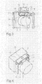
Figur 3- eine schematische, perspektivische Explosionsdarstellung eines hydraulischen Aggregats gemäß einem zweiten Ausführungsbeispiel der vorliegenden Erfindung, und
Figur 4- eine schematische, perspektivische Ansicht des
in
Figur 3 gezeigten hydraulischen Aggregats im zusammengebauten Zustand.
- Figure 1
- 2 shows a schematic top view of a hydraulic unit according to a first exemplary embodiment of the present invention,
- Figure 2
- 2 shows a schematic side view of the hydraulic unit shown in FIG. 1,
- Figure 3
- is a schematic, perspective exploded view of a hydraulic unit according to a second embodiment of the present invention, and
- Figure 4
- is a schematic, perspective view of the hydraulic unit shown in Figure 3 in the assembled state.
Nachfolgend wird unter Bezugnahme auf die Figuren 1 und 2 ein erstes Ausführungsbeispiel der vorliegenden Erfindung beschrieben.The following will refer to FIGS. 1 and 2 a first embodiment of the present invention described.
Wie in Figur 1 gezeigt, umfasst das hydraulische Aggregat
einen Elektromotor 2 als Antrieb und ein Gehäuse 3, in
welchem die weiteren Bauteile des hydraulischen Aggregats,
wie z.B. eine Pumpe und Ventile, angeordnet sind. Aus dem
Gehäuse ragen zwei Anschlussstutzen 5 hervor, an welche
jeweils eine Leitung 4 in Form eines Rohres oder eines
Schlauches angeordnet werden kann. Die Leitungen 4 werden
beispielsweise mittels Überwurfschrauben bzw. Muttern 6 am
Anschlussstutzen 5 befestigt.As shown in Figure 1, the hydraulic unit comprises
an
Um jeden Leitungsanschluss herum ist jeweils ein
elastisches Element 7 angeordnet. Wie aus Figur 1
ersichtlich ist, weisen die elastischen Elemente 7 eine im
Wesentlichen ovale Form auf und umgeben den
Anschlussstutzen 5 des hydraulischen Aggregats 1
vollständig. Wie aus Figur 2 ersichtlich ist, weisen die
elastischen Elemente 7 eine mittlere Ausnehmung 8 auf sowie
einen ersten Rand 9 und einen zweiten Rand 10 auf, wobei
die mittlere Ausnehmung 8 zwischen den beiden Rändern 9, 10
angeordnet ist. Die mittlere Ausnehmung 8 dient zur
Aufnahme eines Metallbandes, welches umlaufend um das
elastische Element 7 angeordnet ist. Eine Halterung 11 ist
an dem umlaufenden Metallband befestigt. Die Halterung 11
dient zur Befestigung des gesamten hydraulischen Aggregats
1 an anderen Karosseriebauteilen des Fahrzeugs. Somit ist
das hydraulische Aggregat 1 über die elastischen Elemente 7
und die Halterung 11 am Fahrzeug befestigt. Aus Gründen
einer besseren Übersichtlichkeit ist die Halterung in Figur
2 nicht dargestellt. There is one around each line connection
Wenn nun Schwingungen, wie beispielsweise Körperschall,
durch den Betrieb des hydraulischen Aggregats 1 erzeugt
werden, werden diese Schwingungen durch die an den
Leitungsanschlüssen angeordneten elastischen Elemente 7
gedämpft und absorbiert. Dadurch wird verhindert, dass die
Schwingungen bzw. der Körperschall über die Halterungen 11
auf das Fahrzeug bzw. über die Leitungen auf andere
Bauteile des Fahrzeugs, insbesondere in den
Fahrzeuginnenraum, übertragen werden.If vibrations, such as structure-borne noise,
generated by the operation of the hydraulic unit 1
, these vibrations are caused by the on the
Line connections arranged elastic elements 7th
steamed and absorbed. This prevents the
Vibrations or structure-borne noise via the
Zur Montage der elastischen Elemente 7 gibt es mehrere
Möglichkeiten. Einerseits können die elastischen Elemente 7
vor Befestigung der Leitungen 4 auf die Leitungsanschlüsse
aufgesteckt werden und anschließend die Leitungen 4
befestigt werden. Eine andere Montagemöglichkeit besteht
darin, dass die elastischen Elemente 7 mit einem Schlitz
versehen werden, so dass sie auch im montierten Zustand der
Leitung 4 über die Leitungsanschlüsse übergezogen werden
können. Das Metallband kann ebenfalls schon im Voraus am
elastischen Element 7 befestigt sein oder einen Schlitz
aufweisen und nachträglich am elastischen Element 7
befestigt werden. Dies kann beispielsweise mittels einer
Schraubverbindung ausgeführt werden, um die beiden Enden
des Metallbandes miteinander zu verbinden.There are several for mounting the
Es ist weiterhin angemerkt, dass das elastische Element 7
auch derart ausgebildet sein kann, dass es den gesamten
Anschlussstutzen 5 überdeckt und zusätzlich auch die
Anschlussmutter 6 zur Befestigung der Leitung 4 überdeckt.
Weiterhin wäre es denkbar, dass auch ein Teil der Leitung 4
durch das elastische Element 7 überdeckt wird.It is further noted that the
Die elastischen Elemente sind in ihrer Geometrie derart
ausgelegt, dass in der Hauptbewegungsrichtung (in Figur 1
durch den Doppelpfeil A gekennzeichnet) der vom
hydraulischen Aggregat 1 erzeugten Schwingungen, eine
überlagerte Beanspruchung aus Druck und Scherung auftritt.
Dies kann beispielsweise durch Vorsehen von Freiräumen im
elastischen Element 7 auf relativ einfache Weise realisiert
werden.The geometry of the elastic elements is such
designed that in the main direction of movement (in Figure 1
marked by the double arrow A) of the
hydraulic unit 1 generated vibrations, a
superimposed stress and shear stress occurs.
This can be done, for example, by providing free spaces in the
Somit kann erfindungsgemäß ein sehr kompakter Aufbau
realisiert werden, wobei nur die elastischen Elemente 7 zur
Aufnahme und Absorption der Schwingungen verwendet werden.Thus, according to the invention, a very compact structure can be achieved
can be realized, with only the
Nachfolgend wird unter Bezugnahme auf die Figuren 3 und 4 ein hydraulisches Aggregat 1 gemäß einem zweiten Ausführungsbeispiel der vorliegenden Erfindung beschrieben. Dabei sind gleiche bzw. funktional gleiche Teile mit den gleichen Bezugszeichen wie im ersten Ausführungsbeispiel bezeichnet.The following will refer to FIGS. 3 and 4 a hydraulic unit 1 according to a second Embodiment of the present invention described. The same or functionally the same parts with the same reference numerals as in the first embodiment designated.
Wie in Figur 3 gezeigt, ist im Unterschied zum ersten
Ausführungsbeispiel beim zweiten Ausführungsbeispiel nur
ein gemeinsames elastisches Element 7 vorgesehen. Das
elastische Element 7 weist zwei Öffnungen 12 auf, welche
die Anschlussstutzen des hydraulischen Aggregats 1
aufnehmen. Das elastische Element 7 weist im Wesentlichen
eine Nierenform auf und ist zur einfacheren Befestigung der
Halterung 11 ebenfalls mit einem Metallband 13 versehen,
welches umlaufend um das elastische Element 7 angeordnet
ist. Das Metallband 13 wird mittels eines Bolzens 18 am
elastischen Element 7 befestigt. Das elastische Element 7
ist mittels Bolzen 14 am Gehäuse 3 befestigt. Die Bolzen 14
sind hohl und weisen ein Innengewinde 15 auf, an welchem
eine Leitung (nicht dargestellt) befestigt werden kann. As shown in Figure 3, is different from the first
Embodiment in the second embodiment only
a common
Zur Befestigung der Halterung 11 sind am umlaufenden
Metallband 13 Befestigungselemente 16 mit Innengewinde,
z.B. Muttern, angebracht. In diese Befestigungselemente 16
werden Bolzen 17, welche durch die Halterungen 11 geführt
sind, eingeschraubt. Somit ist das hydraulische Aggregat 1
über das elastische Element 7 und die Halterungen 11 an dem
Fahrzeug befestigt.To attach the
Damit ermöglicht ein einziges elastisches Element 7 die
Aufnahme von durch Betrieb verursachte Schwingungen des
hydraulischen Aggregats sowohl am hydraulischen Aggregat
selbst als auch an den zugehörigen Leitungen. Dadurch kann
wirkungsvoll eine Übertragung von Schwingungen und
insbesondere von Körperschall auf andere Fahrzeugteile
verhindert werden. Durch die Verwendung von nur einem
elastischen Element ist diese Anordnung besonders
kostengünstig und montagefreundlich.This enables a single
In Figur 3 ist durch den Doppelpfeil A die
Hauptschwingungsrichtung des hydraulischen Aggregats 1
dargestellt, welche durch Betrieb des Elektromotors
verursacht wird. Entsprechend dem im Wesentlichen
zylinderförmigen Gehäuse des Elektromotors weist das
elastische Element 7 die nierenförmige Ausnehmung an der
zum Elektromotor gerichteten Seite auf.In Figure 3 by the double arrow A
Main vibration direction of the hydraulic unit 1
shown by the operation of the electric motor
is caused. According to that essentially
the cylindrical housing of the electric motor has this
Somit können durch die Verwendung eines einzigen
elastischen Elements 7 wirkungsvoll Schwingungen und
Körperschall gedämpft werden, wobei die
Dämpfungsvorrichtung sehr kostengünstig bereitgestellt
werden kann und einen sehr geringen Bauraum einnimmt.Thus, by using a single
Claims (11)
Applications Claiming Priority (2)
| Application Number | Priority Date | Filing Date | Title |
|---|---|---|---|
| DE10326913 | 2003-06-16 | ||
| DE2003126913 DE10326913B4 (en) | 2003-06-16 | 2003-06-16 | Damping device for hydraulic unit |
Publications (2)
| Publication Number | Publication Date |
|---|---|
| EP1488975A1 true EP1488975A1 (en) | 2004-12-22 |
| EP1488975B1 EP1488975B1 (en) | 2007-08-15 |
Family
ID=33394828
Family Applications (1)
| Application Number | Title | Priority Date | Filing Date |
|---|---|---|---|
| EP20040102197 Expired - Lifetime EP1488975B1 (en) | 2003-06-16 | 2004-05-18 | Hydraulic unit |
Country Status (2)
| Country | Link |
|---|---|
| EP (1) | EP1488975B1 (en) |
| DE (1) | DE10326913B4 (en) |
Cited By (1)
| Publication number | Priority date | Publication date | Assignee | Title |
|---|---|---|---|---|
| CN111577672A (en) * | 2020-05-29 | 2020-08-25 | 湖南理工职业技术学院 | Noise-reducing and shock-absorbing device for fan |
Citations (6)
| Publication number | Priority date | Publication date | Assignee | Title |
|---|---|---|---|---|
| DE3025601A1 (en) * | 1980-07-05 | 1982-01-21 | Daimler-Benz Ag, 7000 Stuttgart | Noise attenuating hose or pipe suspension - uses grooved cylindrical dampener element, and B-shaped clip |
| US4569637A (en) * | 1984-02-22 | 1986-02-11 | Walbro Corporation | In-tank fuel pump assembly |
| JPH0733005A (en) * | 1993-07-14 | 1995-02-03 | Toyota Motor Corp | Actuator unit for brake device |
| EP0890778A1 (en) * | 1997-07-11 | 1999-01-13 | Hutchinson | Split sleeve of rubber or similar material for mounting a fastening tab to a rigid pipe |
| US6216734B1 (en) * | 1999-02-18 | 2001-04-17 | Denso Corporation | Rotary device support structure for fuel supply apparatus |
| US20020190572A1 (en) * | 2001-06-13 | 2002-12-19 | Unisia Jecs Corporation | Support structure and method for supporting a hydraulic unit of a brake system on a vehicle body, and hydraulic unit arrangement for a vehicle brake system |
Family Cites Families (1)
| Publication number | Priority date | Publication date | Assignee | Title |
|---|---|---|---|---|
| DE19930635A1 (en) * | 1999-07-02 | 2001-01-04 | Mannesmann Rexroth Ag | Energy converter for converting electricity to hydraulic power, with electric motor and hydraulic pump independently attached to base frame |
-
2003
- 2003-06-16 DE DE2003126913 patent/DE10326913B4/en not_active Expired - Fee Related
-
2004
- 2004-05-18 EP EP20040102197 patent/EP1488975B1/en not_active Expired - Lifetime
Patent Citations (6)
| Publication number | Priority date | Publication date | Assignee | Title |
|---|---|---|---|---|
| DE3025601A1 (en) * | 1980-07-05 | 1982-01-21 | Daimler-Benz Ag, 7000 Stuttgart | Noise attenuating hose or pipe suspension - uses grooved cylindrical dampener element, and B-shaped clip |
| US4569637A (en) * | 1984-02-22 | 1986-02-11 | Walbro Corporation | In-tank fuel pump assembly |
| JPH0733005A (en) * | 1993-07-14 | 1995-02-03 | Toyota Motor Corp | Actuator unit for brake device |
| EP0890778A1 (en) * | 1997-07-11 | 1999-01-13 | Hutchinson | Split sleeve of rubber or similar material for mounting a fastening tab to a rigid pipe |
| US6216734B1 (en) * | 1999-02-18 | 2001-04-17 | Denso Corporation | Rotary device support structure for fuel supply apparatus |
| US20020190572A1 (en) * | 2001-06-13 | 2002-12-19 | Unisia Jecs Corporation | Support structure and method for supporting a hydraulic unit of a brake system on a vehicle body, and hydraulic unit arrangement for a vehicle brake system |
Non-Patent Citations (1)
| Title |
|---|
| PATENT ABSTRACTS OF JAPAN vol. 1995, no. 05 30 June 1995 (1995-06-30) * |
Cited By (1)
| Publication number | Priority date | Publication date | Assignee | Title |
|---|---|---|---|---|
| CN111577672A (en) * | 2020-05-29 | 2020-08-25 | 湖南理工职业技术学院 | Noise-reducing and shock-absorbing device for fan |
Also Published As
| Publication number | Publication date |
|---|---|
| DE10326913B4 (en) | 2005-06-23 |
| EP1488975B1 (en) | 2007-08-15 |
| DE10326913A1 (en) | 2005-01-20 |
Similar Documents
| Publication | Publication Date | Title |
|---|---|---|
| EP1307667B1 (en) | Device for the elastic mounting of a hydraulic unit in a motor vehicle braking system on a vehicle | |
| DE4334924C2 (en) | Fastening device for a vibration-preventing coil spring | |
| EP1152156A1 (en) | Device particularly for acoustic dampened fastening | |
| DE102009029569A1 (en) | Device for the vibration-damping mounting of a fluid aggregate and associated fluid aggregate | |
| EP1735541A1 (en) | Brake mechanism | |
| EP2342111A1 (en) | Brake device arrangement and auxiliary device arrangement of a pneumatic brake system of a vehicle | |
| DE202016107350U1 (en) | Damped fastener assembly | |
| EP1597491B1 (en) | Brake caliper | |
| DE602006000829T2 (en) | Vibration damping device and structure with this | |
| DE102012011601A1 (en) | Constraint free fastening system, particularly for attaching steering gear housing at vehicle body, has component with two fastening feet, while another component is provided with two receptacles | |
| DE102008045461A1 (en) | Acoustic side cover for a motor | |
| WO2007118558A1 (en) | Holding device for an engine/pump assembly, in particular for a power steering system | |
| DE102010047160A1 (en) | Arrangement for mounting vibrating unit on steering wheel, has steering wheel rim which is connected with steering wheel hub through support element | |
| EP2008886A2 (en) | Fixing clip | |
| DE10326913B4 (en) | Damping device for hydraulic unit | |
| DE10349702B4 (en) | Vibration-damping unit holding device | |
| DE102018128430A1 (en) | Attaching a steering lock to an additional holder | |
| DE102013109883A1 (en) | screw | |
| EP0942513A2 (en) | Electric motor | |
| DE60300535T2 (en) | Internal combustion engine with a pump and method for replacing the pump | |
| DE102017105368B4 (en) | Compressor housing for an air conditioning compressor of a vehicle | |
| DE60009401T2 (en) | Device for fixing a heat shield for an oil pump | |
| WO2005039946A1 (en) | Hydraulic power unit comprising an integrated sensor device | |
| DE102005014234B4 (en) | Fixing system with at least one fastener connected to a support member | |
| DE102011079617A1 (en) | Screw joint for vibration isolation mounting of component to machine structure, comprises machine screw that establishes wall through-hole of component and is screwed into machine structure |
Legal Events
| Date | Code | Title | Description |
|---|---|---|---|
| PUAI | Public reference made under article 153(3) epc to a published international application that has entered the european phase |
Free format text: ORIGINAL CODE: 0009012 |
|
| AK | Designated contracting states |
Kind code of ref document: A1 Designated state(s): AT BE BG CH CY CZ DE DK EE ES FI FR GB GR HU IE IT LI LU MC NL PL PT RO SE SI SK TR |
|
| AX | Request for extension of the european patent |
Extension state: AL HR LT LV MK |
|
| 17P | Request for examination filed |
Effective date: 20050622 |
|
| AKX | Designation fees paid |
Designated state(s): CH DE FR GB IT LI |
|
| GRAP | Despatch of communication of intention to grant a patent |
Free format text: ORIGINAL CODE: EPIDOSNIGR1 |
|
| RTI1 | Title (correction) |
Free format text: HYDRAULIC UNIT |
|
| RBV | Designated contracting states (corrected) |
Designated state(s): CH FR GB IT LI |
|
| REG | Reference to a national code |
Ref country code: DE Ref legal event code: 8566 |
|
| GRAS | Grant fee paid |
Free format text: ORIGINAL CODE: EPIDOSNIGR3 |
|
| GRAA | (expected) grant |
Free format text: ORIGINAL CODE: 0009210 |
|
| AK | Designated contracting states |
Kind code of ref document: B1 Designated state(s): CH FR GB IT LI |
|
| REG | Reference to a national code |
Ref country code: GB Ref legal event code: FG4D Free format text: NOT ENGLISH |
|
| REG | Reference to a national code |
Ref country code: CH Ref legal event code: EP |
|
| GBT | Gb: translation of ep patent filed (gb section 77(6)(a)/1977) |
Effective date: 20071128 |
|
| ET | Fr: translation filed | ||
| PLBE | No opposition filed within time limit |
Free format text: ORIGINAL CODE: 0009261 |
|
| STAA | Information on the status of an ep patent application or granted ep patent |
Free format text: STATUS: NO OPPOSITION FILED WITHIN TIME LIMIT |
|
| 26N | No opposition filed |
Effective date: 20080516 |
|
| REG | Reference to a national code |
Ref country code: CH Ref legal event code: PL |
|
| PG25 | Lapsed in a contracting state [announced via postgrant information from national office to epo] |
Ref country code: LI Free format text: LAPSE BECAUSE OF NON-PAYMENT OF DUE FEES Effective date: 20080531 Ref country code: CH Free format text: LAPSE BECAUSE OF NON-PAYMENT OF DUE FEES Effective date: 20080531 |
|
| PGFP | Annual fee paid to national office [announced via postgrant information from national office to epo] |
Ref country code: GB Payment date: 20100324 Year of fee payment: 7 |
|
| PGFP | Annual fee paid to national office [announced via postgrant information from national office to epo] |
Ref country code: FR Payment date: 20100608 Year of fee payment: 7 |
|
| PGFP | Annual fee paid to national office [announced via postgrant information from national office to epo] |
Ref country code: IT Payment date: 20100526 Year of fee payment: 7 |
|
| GBPC | Gb: european patent ceased through non-payment of renewal fee |
Effective date: 20110518 |
|
| REG | Reference to a national code |
Ref country code: FR Ref legal event code: ST Effective date: 20120131 |
|
| PG25 | Lapsed in a contracting state [announced via postgrant information from national office to epo] |
Ref country code: IT Free format text: LAPSE BECAUSE OF NON-PAYMENT OF DUE FEES Effective date: 20110518 |
|
| PG25 | Lapsed in a contracting state [announced via postgrant information from national office to epo] |
Ref country code: FR Free format text: LAPSE BECAUSE OF NON-PAYMENT OF DUE FEES Effective date: 20110531 |
|
| PG25 | Lapsed in a contracting state [announced via postgrant information from national office to epo] |
Ref country code: GB Free format text: LAPSE BECAUSE OF NON-PAYMENT OF DUE FEES Effective date: 20110518 |