EP1488910A1 - Procédé et appareil pour fabriquer un film thermoplastique - Google Patents
Procédé et appareil pour fabriquer un film thermoplastique Download PDFInfo
- Publication number
- EP1488910A1 EP1488910A1 EP03024284A EP03024284A EP1488910A1 EP 1488910 A1 EP1488910 A1 EP 1488910A1 EP 03024284 A EP03024284 A EP 03024284A EP 03024284 A EP03024284 A EP 03024284A EP 1488910 A1 EP1488910 A1 EP 1488910A1
- Authority
- EP
- European Patent Office
- Prior art keywords
- film
- air
- bubble
- microporous layer
- film bubble
- Prior art date
- Legal status (The legal status is an assumption and is not a legal conclusion. Google has not performed a legal analysis and makes no representation as to the accuracy of the status listed.)
- Granted
Links
Images


Classifications
-
- B—PERFORMING OPERATIONS; TRANSPORTING
- B29—WORKING OF PLASTICS; WORKING OF SUBSTANCES IN A PLASTIC STATE IN GENERAL
- B29C—SHAPING OR JOINING OF PLASTICS; SHAPING OF MATERIAL IN A PLASTIC STATE, NOT OTHERWISE PROVIDED FOR; AFTER-TREATMENT OF THE SHAPED PRODUCTS, e.g. REPAIRING
- B29C48/00—Extrusion moulding, i.e. expressing the moulding material through a die or nozzle which imparts the desired form; Apparatus therefor
- B29C48/25—Component parts, details or accessories; Auxiliary operations
- B29C48/88—Thermal treatment of the stream of extruded material, e.g. cooling
- B29C48/90—Thermal treatment of the stream of extruded material, e.g. cooling with calibration or sizing, i.e. combined with fixing or setting of the final dimensions of the extruded article
- B29C48/908—Thermal treatment of the stream of extruded material, e.g. cooling with calibration or sizing, i.e. combined with fixing or setting of the final dimensions of the extruded article characterised by calibrator surface, e.g. structure or holes for lubrication, cooling or venting
-
- B—PERFORMING OPERATIONS; TRANSPORTING
- B29—WORKING OF PLASTICS; WORKING OF SUBSTANCES IN A PLASTIC STATE IN GENERAL
- B29C—SHAPING OR JOINING OF PLASTICS; SHAPING OF MATERIAL IN A PLASTIC STATE, NOT OTHERWISE PROVIDED FOR; AFTER-TREATMENT OF THE SHAPED PRODUCTS, e.g. REPAIRING
- B29C48/00—Extrusion moulding, i.e. expressing the moulding material through a die or nozzle which imparts the desired form; Apparatus therefor
- B29C48/03—Extrusion moulding, i.e. expressing the moulding material through a die or nozzle which imparts the desired form; Apparatus therefor characterised by the shape of the extruded material at extrusion
- B29C48/09—Articles with cross-sections having partially or fully enclosed cavities, e.g. pipes or channels
- B29C48/10—Articles with cross-sections having partially or fully enclosed cavities, e.g. pipes or channels flexible, e.g. blown foils
-
- B—PERFORMING OPERATIONS; TRANSPORTING
- B29—WORKING OF PLASTICS; WORKING OF SUBSTANCES IN A PLASTIC STATE IN GENERAL
- B29C—SHAPING OR JOINING OF PLASTICS; SHAPING OF MATERIAL IN A PLASTIC STATE, NOT OTHERWISE PROVIDED FOR; AFTER-TREATMENT OF THE SHAPED PRODUCTS, e.g. REPAIRING
- B29C48/00—Extrusion moulding, i.e. expressing the moulding material through a die or nozzle which imparts the desired form; Apparatus therefor
- B29C48/25—Component parts, details or accessories; Auxiliary operations
- B29C48/88—Thermal treatment of the stream of extruded material, e.g. cooling
- B29C48/90—Thermal treatment of the stream of extruded material, e.g. cooling with calibration or sizing, i.e. combined with fixing or setting of the final dimensions of the extruded article
- B29C48/901—Thermal treatment of the stream of extruded material, e.g. cooling with calibration or sizing, i.e. combined with fixing or setting of the final dimensions of the extruded article of hollow bodies
- B29C48/903—Thermal treatment of the stream of extruded material, e.g. cooling with calibration or sizing, i.e. combined with fixing or setting of the final dimensions of the extruded article of hollow bodies externally
-
- B—PERFORMING OPERATIONS; TRANSPORTING
- B29—WORKING OF PLASTICS; WORKING OF SUBSTANCES IN A PLASTIC STATE IN GENERAL
- B29C—SHAPING OR JOINING OF PLASTICS; SHAPING OF MATERIAL IN A PLASTIC STATE, NOT OTHERWISE PROVIDED FOR; AFTER-TREATMENT OF THE SHAPED PRODUCTS, e.g. REPAIRING
- B29C48/00—Extrusion moulding, i.e. expressing the moulding material through a die or nozzle which imparts the desired form; Apparatus therefor
- B29C48/25—Component parts, details or accessories; Auxiliary operations
- B29C48/88—Thermal treatment of the stream of extruded material, e.g. cooling
- B29C48/911—Cooling
- B29C48/9115—Cooling of hollow articles
- B29C48/912—Cooling of hollow articles of tubular films
- B29C48/913—Cooling of hollow articles of tubular films externally
-
- B—PERFORMING OPERATIONS; TRANSPORTING
- B29—WORKING OF PLASTICS; WORKING OF SUBSTANCES IN A PLASTIC STATE IN GENERAL
- B29C—SHAPING OR JOINING OF PLASTICS; SHAPING OF MATERIAL IN A PLASTIC STATE, NOT OTHERWISE PROVIDED FOR; AFTER-TREATMENT OF THE SHAPED PRODUCTS, e.g. REPAIRING
- B29C55/00—Shaping by stretching, e.g. drawing through a die; Apparatus therefor
- B29C55/28—Shaping by stretching, e.g. drawing through a die; Apparatus therefor of blown tubular films, e.g. by inflation
Definitions
- the invention relates to a method for producing a film thermoplastic, in which a plastic melt from a blow head fed by at least one extruder to form one Film bubble emerges and the film bubble subsequently a calibration device passes through, in which it is calibrated to a predeterminable diameter and then laid flat to a film web by means of a flat laying device and afterwards is wound up, for example.
- thermoplastic material Such a manufacturing process for the production of also as blown film designated films made of thermoplastic material is widely known.
- the plastic in thermoplastic i.e. melted state from the usually annular opening of the Blow head emerges and is immediately inflated to a film bubble, which subsequently cooling below the solidification temperature solidified.
- the film bubble is also passed through a calibration device and calibrated in diameter and then from one Lay-flat device laid flat to form a double film and subsequently wound.
- the calibration device is usually in the form of a so-called Calibration basket executed, the outside of the film bubble like a Cylinder surrounds and includes a plurality of calibration arms, the outside are in contact with the circumference of the film bubble to hold it in its Define and calibrate the diameter.
- the calibration arms can For example, have a plurality of rotatable plastic rollers that on unroll the surface of the bubble and calibrate it at the same time. Also Embodiments with rotating brushes or the like are known become.
- the calibration arms of such a calibration basket are usually adjustable holder, so that different diameters of the film bubble can be set and calibrated.
- a contactless calibration and / or laying the Foil bubble can therefore be considerable in certain applications Be an advantage.
- EP 0 273 739 A1 has already proposed that Foil bubble between strong on the inside and outside of the bubble attacking air streams to make contact with a contact friction the resulting surface impairments of the film bubble to avoid.
- the necessary system effort with powerful Blowers, air lines and corresponding control technology is, however very high and moreover the problem arises that when too strong Air currents undesirable temperature influences of the film bubble can occur that negatively affect the quality of the film obtained.
- EP 1 144 292 B1 also discloses a contactless device Guide or treat a running material web, such as a plastic film become known in which a gaseous fluid from a chamber Guide the web exits, the gas permeable wall from a metal-containing material is made with open pores.
- a contactless device Guide or treat a running material web such as a plastic film become known in which a gaseous fluid from a chamber Guide the web exits, the gas permeable wall from a metal-containing material is made with open pores.
- the device is used to guide an already high stability Web used in a coating device.
- the object of the invention is to develop a method for producing a film propose thermoplastic, in which, bypassing the Disadvantages of the prior art are non-contact calibration and Flattening of the incomplete especially during calibration solidified and solidified film web can take place.
- the method according to the invention thus formed is the Based on the knowledge that the previously used Foil guide elements for the calibration device and / or the Flat lay the airflow from the at defined intervals Air outlet openings arranged from each other result the air escaping the high required for the formation of the air cushion Air speed and high mass throughput always in the form of turbulent Air flows out, which create an inhomogeneous air cushion, so that a uniform calibration and flat lay of the film bubble is not can be effected and also touches between the Calibration device and / or flat laying device and the film bubble Duration cannot be excluded.
- the film bubble facing surface of the film guide elements from one air-permeable microporous layer is formed and the Air flow supplied through this microporous film guide elements Layer is passed through, the microporous layer in the air flow divides a large number of laminar partial air flows and the laminar partial air flows each through individual pores of the microporous layer in the direction of Exit the bubble and form the laminar air cushion.
- the air-permeable one microporous layer advantageously has an average pore size of 5 to 100 ⁇ m, whereby to achieve a sufficient support effect of the still unstable and still willing to expand due to inflation to the film bubble Foil bubble a pore size between 30 and 100 microns as preferred is seen.
- the film guiding elements when subjected to an air flow of 0.5 to 4 bar, can only contribute with an air flow rate in the direction of the film bubble of correspondingly 0.2 l / min dm 2 at 0.5 bar to 1.6 l / min dm 2 4 bar can be operated, even with this low air throughput due to the formation of a laminar air cushion a contactless guidance is guaranteed.
- the invention further comprises an apparatus for producing a film thermoplastic, which has at least one extruder with a Blow head for the exit of a film bubble from the plastic, one on the outside on the film bubble acting calibration device and one of the Flat lay device downstream of the calibration device for the film bubble comprises, the calibration device and / or the flat laying device
- a film thermoplastic which has at least one extruder with a Blow head for the exit of a film bubble from the plastic, one on the outside on the film bubble acting calibration device and one of the Flat lay device downstream of the calibration device for the film bubble
- the calibration device and / or the flat laying device Have film guide elements that can be acted upon by an air stream are and in the area of the surface of the film bubble Foil guiding elements air outlet openings for the outlet of the supplied Air flow are provided.
- This device for producing a film from thermoplastic material points to the desired achievement of a uniform non-contact Calibration and / or laying flat of the film bubble on film guide elements, whose surface facing the film bubble has an air-permeable microporous layer with an average pore size of 5 to 100 ⁇ m is trained.
- the too calibrating and / or laying flat film bubble in the invention Device still unstable and due to the expansion with high Expansion tendency is provided for reliable non-contact Calibration and / or laying the same a not insignificant Radial force on the film bubble from the Calibration device and / or flat laying device on the outer surface of the Apply a film bubble.
- this force can only be applied if that used for non-contact guidance, calibration and laying flat Air cushion has a certain minimum intensity, which is particularly at Formation of the air-permeable microporous layer with a middle Pore size from 30 to 100 microns.
- the surface of the film bubble facing the Microporous air-permeable layer serving film guide element advantageous to a thickness of 0.5 to 2.0 mm, because with these layer thicknesses Desired fine distribution of the air flow with a simultaneous high Air permeability of the microporous layer is guaranteed.
- microporous layers with an inventive required average pore size of about 5 to 100 microns, preferably about 30 to 100 ⁇ m can be achieved in different ways.
- the microporous layer based on a powder mixture with several Components of different melting temperatures can be produced.
- the air-permeable microporous layer based on Metal and ceramic components are manufactured.
- a preferred embodiment of the invention Device used film guide elements provides that this one Have housing which has a rear wall facing away from the film bubble and one facing the film bubble and having air outlet openings Front wall as well as the rear wall and the front wall to form one has sealed air chamber connecting peripheral wall.
- the rear wall and the peripheral wall are airtight, while on the front wall having the air outlet openings the Air-permeable microporous layer on the film bubble facing Side is applied through which ultimately through the air outlet openings in the front wall air in the direction of the film bubble from the Film guide element emerges.
- To supply the airflow is in the area the rear wall and / or the peripheral wall an air inlet opening in the Air chamber of the housing provided.
- the air chamber is a particularly advantageous embodiment of the invention inside the housing by means of intermediate webs communicating sub-chambers divided and serves to distribute the supplied air flow.
- the intermediate webs are just like the peripheral wall with the rear wall connected, preferably forming the rear wall with the Front wall facing surface of integrally formed peripheral wall and intermediate webs is provided.
- Such an integral training of Perimeter wall and the intermediate webs can, for example, by area-by-area milling or the like in the area of the later Partial chambers take place.
- the front wall on the peripheral wall and the intermediate webs put on and welded airtight along the peripheral wall, e.g. by means of laser welding.
- the dividers can also pass through individual spot welds are connected to the front wall in order to this provides greater stability when later loaded with a To give compressed air flow.
- the intermediate webs also increase the rigidity of the rear wall, so that the result is an extremely compact and dimensionally stable housing is obtained. It has been shown in the context of the invention that Production of the housing from a metallic material a 2-part Housing consisting of a 2mm thick rear wall, through which 1mm deep milled circumferential walls and intermediate webs corresponding height of 1 mm and a 2mm thick Front wall with air outlet openings a surprisingly good and uniform air distribution and formation of the desired air cushion offers.
- a uniform, homogeneous air cushion between the Foil bubble and the surface of the Generated film guide element behaves.
- Subdivision of the air chamber into one another by means of intermediate webs communicating subchambers also ensures that there are over the entire surface of the film bubble facing the Foil guiding element does not consider partial air cushion pressure differences there, so that an extremely even non-contact Guidance and calibration or flat lay of the film bubble is achieved.
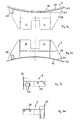
- the device for producing a film shown in FIG Thermoplastic does not include any of the details shown blow head 1, the extruder not visible here with melted thermoplastic in a manner known per se is applied.
- the blow head 1 passes over an annular ring at the top Outlet opening of the plastic in a thermoplastic state and will immediately inflated to a film bubble 4 and vertically in the direction of arrow L. dissipated above.
- This film bubble 4 therefore has a circular shape Cross section with a central axis M.
- thermoplastic and solidified state of the Foil bubble 4 are characterized by a so-called frost line, which in the Figure 1 is indicated with reference numeral F.
- FIG. 1 also shows the inside of the film bubble 4 in itself Known manner arranged internal air exchanger 7, the support of the Foil bubble 4 on the inside serves the same.
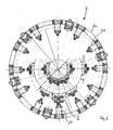
- a calibration device 2 is already just above the blow head 1 arranged in accordance with the details from supervision Representation in Figure 6 can be seen.
- the calibration device 2 serves the To fix the film tube 4 in its diameter around the central axis M, for which purpose they extend from the outside in the radial direction onto the circumference of the film bubble 4 acts.
- the calibration device 2 includes a Foil bubble 4 surrounding calibration basket 20, at the Inside in the direction of the one passing through the calibration device 2 Foil bubble 4 a plurality of support arms 21 are arranged.
- This Support arms 21 carry on their free, the outer circumference of the film bubble 4 adjacent end each film guide elements 5, their number and Arrangement in Figure 1 are shown only schematically, their real Arrangement around the circumference of the film bubble 4 in a uniform manner However, distances can be seen from the further illustration according to FIG. 6.
- a single end adjacent to the film bubble 4 of each support arm 21 attached film guide element 5 is in different views in the Figures 3a to 3d shown.
- This film guide element 5 comprises in its essential components Housing 50, which comprises a rear wall 51 and a front wall 52.
- Housing 50 which comprises a rear wall 51 and a front wall 52.
- the rear wall 51 is in the installation position of the Foil guide element of the film bubble 4 facing away while the Front side 52 of the housing 50 faces the film bubble 4.
- the film guide member 5 further includes one with the rear wall 51 of the Housing 50 connected mounting flange 58 with which the Film guide element 5 on the support arm 21 within the calibration device 2 is attached.
- the basic structure of the rear wall 51 and front wall 52 of the Foil guide element 5 is also in more detail from the 4a to 4c and 5a to 5b seen.
- the rear wall shown in Figures 4a to 4c in a straight line 51 of the film guide element is, for example, from a air-impermeable metallic material and exhibits along its the front wall 52 facing surface a circumferential Circumferential wall 53, which is also airtight and for example, is welded onto the rear wall 51. It is preferred by Milled or the like made with the rear wall 51 left, i.e. molded integrally with this.
- This air chamber 54 is also by means of additional ones on the rear wall 51 trained intermediate webs 56, between which openings 57 are formed, approximately the same size and over the openings 57 Partial air chambers communicating with each other, divided over the extend the entire interior of the air chamber 54 evenly. Also the Intermediate webs 56 are preferably together with the peripheral wall 53 made by milling, i.e. integrally connected to the rear wall 51.
- an air inlet opening 55 in Formed a bore with an associated connector, on the an air flow E1 can be introduced into the interior of the air chamber 54.
- the when using the film guide element 5 facing the film bubble 4 Front wall 52 of the same is in turn with a variety of, for example Distribute evenly over the entire surface Provided air outlet openings 52b, one of which is exemplary in the 5b is shown in a greatly enlarged diameter.
- the partial air chamber on the far right is an example Arrangement of the air outlet openings 52b distributed closer to the grid indicated.
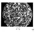
- This Microporous air-permeable layer 15 can be based, for example, on a Powder mixture with several components of different Melting temperatures, e.g. based on metal and ceramic components be produced and is characterized by an extremely finely divided Arrangement of micropores 150, which have an average pore diameter from about 5 to 100 microns, preferably 30 to 100 microns.
- This microporous layer is in a thickness d1 of 0.5 to 2.0 mm on the Applied front wall 52 and forms the surface of the film bubble 4th directly opposite surface of the film guide element 5.
- the one into the air chamber 54 via the air inlet opening 55 in the rear wall 51 entering air flow according to arrow E1 thus passes through the air outlet openings 52b in the front wall 52 of the housing 50 into that applied thereon microporous layer 15 and is from there on the individual irregular and closely adjacent micropores 150 therethrough led to the outer surface of the microporous layer 15, which at the same time the film bubble 4 is opposite.
- this serves on the outside of the housing 50 Film guide devices 5 applied microporous layer 15 to the through the air outlet openings 52b at high speed Split airflow E2 into a multitude of laminar smallest airflows E3 and from the individual finely divided pores with an average pore size of 5 to 100 ⁇ m, preferably 30 to 100 ⁇ m, so that the result a laminar air cushion on the surface of the film bubble 4 Film guide element 5 is generated.
- the working range for the supplied air flow E1 of such a film guiding element 5 is approximately 0.5 to 4 bar, depending on the product driven, ie the tubular film web produced. If an air flow E1 of an excess pressure of 0.5 bar is applied to the film guide element, this results in an air consumption of approximately 0.2 l / min dm 2 , ie this air quantity emerges from the microporous layer 15 in the form of minute air flows E3. When an air flow E1 of 4 bar gauge pressure is applied, the air consumption is approximately 1.6 l / min dm 2 .
- the partial air chambers the later air chamber 54 leaving the peripheral wall 53 and the Intermediate webs 56 milled approximately 1 mm deep, so that a continuous Rear wall 51 with a thickness of about 1 mm remains.
- the housing 50 produced in this way is then also the same e.g. 2mm thick front wall 52 with those already formed therein Air outlet openings 52b placed and all around and airtight with the Circumferential wall 53 welded, e.g. laser welded.
- the placed front wall 52 is also on the intermediate webs 56 by means of Spot welds attached to increase stability.
- the front wall facing away from the rear wall 51 becomes the front wall 52 ground so that any welds that may be present are removed and then the mentioned microporous layer 15 may have a thickness of about 1 mm be applied.
- This concavely curved surface can be due to the only required small layer thickness d1 of the microporous layer 15 of only 0.5 to 2 mm immediately by applying it to the desired curvature having housing 50 are generated.
- the housing 50 already provided with the microporous layer 15 from its rectilinear, flat extension deformed until the desired There is curvature.
- the microporous layer allows such a deformation without losing their desirable porosity. Then there is one Connection of the housing 50 to the mounting flange 58, e.g. by Welding.
- the flat laying device has two corresponding Angle arranged on opposite sides of the film bubble 4 Flat laying frame 30, on which in turn support arms 31 are attached at their free end facing the film bubble 4 in each case
- the in Foil guiding elements 5 used in a flat laying device 3 have the plane extension as shown in FIGS. 4a to 4c, 5a, 5b and extend over the entire width to be laid flat
- Double film web 4a Regarding the further structure can refer to the above Explanations are referred.
- Each film guide element 5 in turn has an air inlet opening 55 for the air flow E1, which together via a feed line 33 to the Flat laying device 3 is brought up.
- the Flat lay device 3 is formed by the construction of the film guide elements 5 with an applied on the side facing the film bubble 4 air-permeable microporous layer 15, from which laminar partial air flows E3 emerge and a laminar air cushion 22 or 32 for the contactless Guide the film bubble 4 generate a completely non-contact Calibration or laying flat of the bubble 4 enables.
- Such calibration devices 2 and laying 3 can therefore Guiding, calibration or laying flat even strongly adhesive film bubbles 4, e.g. in the production of EVA composite films, PIB composite films and Associated with ionomers can be used in PE-LLD films without causing it adheres to the film guide elements 5.
- microporous layer 15 used according to the invention preferably on Base made of metal and ceramic components and on the case 50 is applied in the area of the front 42 of the same, it can with known method in a simple manner on the previously manufactured housing 50 are deposited in the area of the front wall 52 and subsequently e.g. can be brought into the desired shape by grinding.
- the film guide elements proposed in the context of the invention stand out in addition to their microporous layer for producing the laminar Air cushion particularly characterized by its compactness, for example already with a total thickness of at most 5mm including the microporous layer forming a uniform air cushion for Enable calibration or lay-flat applications in film extrusion.
Landscapes
- Engineering & Computer Science (AREA)
- Mechanical Engineering (AREA)
- Physics & Mathematics (AREA)
- Thermal Sciences (AREA)
- Extrusion Moulding Of Plastics Or The Like (AREA)
- Medical Preparation Storing Or Oral Administration Devices (AREA)
- Laminated Bodies (AREA)
Applications Claiming Priority (4)
| Application Number | Priority Date | Filing Date | Title |
|---|---|---|---|
| DE20309429U | 2003-06-17 | ||
| DE20309429U DE20309429U1 (de) | 2003-06-17 | 2003-06-17 | Abzugsvorrichtung einer Schlauchfolienextrusionsanlage |
| DE10341508 | 2003-09-05 | ||
| DE10341508 | 2003-09-05 |
Publications (2)
| Publication Number | Publication Date |
|---|---|
| EP1488910A1 true EP1488910A1 (fr) | 2004-12-22 |
| EP1488910B1 EP1488910B1 (fr) | 2007-01-24 |
Family
ID=33420028
Family Applications (1)
| Application Number | Title | Priority Date | Filing Date |
|---|---|---|---|
| EP03024284A Expired - Lifetime EP1488910B1 (fr) | 2003-06-17 | 2003-10-23 | Appareil pour fabriquer un film thermoplastique |
Country Status (7)
| Country | Link |
|---|---|
| US (2) | US7479003B2 (fr) |
| EP (1) | EP1488910B1 (fr) |
| CN (1) | CN100553945C (fr) |
| AT (1) | ATE352408T1 (fr) |
| DE (1) | DE50306379D1 (fr) |
| DK (1) | DK1488910T3 (fr) |
| ES (1) | ES2280666T3 (fr) |
Cited By (10)
| Publication number | Priority date | Publication date | Assignee | Title |
|---|---|---|---|---|
| WO2005084919A1 (fr) * | 2004-03-04 | 2005-09-15 | Windmöller & Hölscher Kg | Systeme d'extrusion pour feuille soufflee |
| DE102005038730A1 (de) * | 2005-08-15 | 2007-02-22 | Windmöller & Hölscher Kg | Verbesserte Luftführung an der Folienblase |
| DE102005033206B4 (de) * | 2005-07-13 | 2010-12-02 | Windmöller & Hölscher Kg | Blasfolienanlage sowie Verfahren zum Betrieb derselben |
| DE102005033205B4 (de) | 2005-07-13 | 2010-12-02 | Windmöller & Hölscher Kg | Verfahren zur auftragsbezogenen Änderung des Folienschlauchformats von einem Ausgangsformat zu einem Endformat sowie Blasfolienanlage, an der diese Änderung durchführbar ist |
| DE102005051874B4 (de) * | 2005-10-29 | 2011-06-22 | Windmöller & Hölscher KG, 49525 | Blasfolienextrusionsanlage |
| EP2368687A3 (fr) * | 2010-03-26 | 2012-02-08 | Nitto Denko Corporation | Appareil et procédé de moulage par extrusion de gonflage de feuille adhésive sensible à la pression |
| US8210837B2 (en) | 2005-12-21 | 2012-07-03 | Windmoeller & Hoelscher Kg | Sizing cage adjustment |
| DE102004031366B4 (de) * | 2004-03-04 | 2014-09-04 | Windmöller & Hölscher Kg | Blasfolienextrusionsanlage |
| DE10354503B4 (de) * | 2003-11-21 | 2014-09-04 | Kiefel Extrusion Gmbh | Blasfolienanlage mit einem Kalibrierkorb als Schlauchkalibrierung und/oder als Schlauchführung |
| US9457526B2 (en) | 2013-05-08 | 2016-10-04 | Kdesign Gmbh | Calibration device for calibrating an extruded film tube |
Families Citing this family (9)
| Publication number | Priority date | Publication date | Assignee | Title |
|---|---|---|---|---|
| CN101720271A (zh) * | 2007-06-28 | 2010-06-02 | 莱芬豪舍机器制造公司 | 用于薄膜软管的传送部件 |
| DE102008010796A1 (de) * | 2007-10-18 | 2009-04-23 | Reifenhäuser GmbH & Co. KG Maschinenfabrik | Verfahren und Vorrichtung zur kontinuierlichen Herstellung eines Extrudats aus feinteiligem Pflanzenmaterial und einem thermoplastischen Material |
| EP2298678B1 (fr) * | 2009-09-18 | 2012-02-22 | Reifenhäuser GmbH & Co. Maschinenfabrik | Dispositif d'enroulement |
| US11695847B2 (en) * | 2014-08-14 | 2023-07-04 | Nokia Solutions And Networks Oy | Throughput guidance based on user plane insight |
| CN105109173A (zh) * | 2015-08-06 | 2015-12-02 | 江阴升辉包装材料有限公司 | 一种多层共挤制备软管片材的方法 |
| EP3216583B1 (fr) | 2016-03-11 | 2021-04-28 | Reifenhäuser GmbH & Co. KG Maschinenfabrik | Adaptateur de coextrusion |
| CN118223137A (zh) | 2017-11-22 | 2024-06-21 | 挤压集团公司 | 熔喷模头尖端组件和方法 |
| CN108422648B (zh) * | 2018-04-28 | 2020-02-04 | 重庆瑞霆塑胶有限公司 | 吹膜机 |
| CN110292781B (zh) * | 2019-07-31 | 2023-03-14 | 深圳市如萌涂文化传播有限公司 | 一种diy布娃娃自动生产线 |
Citations (6)
| Publication number | Priority date | Publication date | Assignee | Title |
|---|---|---|---|---|
| US3008185A (en) * | 1958-01-24 | 1961-11-14 | Du Pont | Extrusion process and apparatus for forming tubular film |
| US3321563A (en) * | 1962-10-12 | 1967-05-23 | Basf Ag | Production of highly transparent films from thermoplastics |
| US3950466A (en) * | 1972-08-09 | 1976-04-13 | Imperial Chemical Industries Limited | Stabilising sleeve |
| US4017575A (en) * | 1972-03-08 | 1977-04-12 | E. I. Du Pont De Nemours And Company | Production of a flat thermoplastic film by passing the film over a bearing having a lubricating fluid on the surface thereof |
| US5128076A (en) * | 1991-03-21 | 1992-07-07 | Minnesota Mining And Manufacturing Company | Apparatus and method for producing an elongate strip of material |
| WO2003033241A1 (fr) * | 2001-10-12 | 2003-04-24 | Ole-Bendt Rasmussen | Orientation longitudinale d'un film thermoplastique tubulaire |
Family Cites Families (11)
| Publication number | Priority date | Publication date | Assignee | Title |
|---|---|---|---|---|
| US3097971A (en) * | 1960-11-09 | 1963-07-16 | British Iron Steel Research | Method of and apparatus for supporting or guiding strip material |
| CH519981A (de) | 1971-02-08 | 1972-03-15 | Windmoeller & Hoelscher | Flachlege- und Abzugvorrichtung für im Blasverfahren hergestellte Kunststoffschlauchfolien |
| US4176775A (en) * | 1977-03-28 | 1979-12-04 | Beloit Corporation | Inhibiting noise in sheet spreaders |
| US4728277A (en) | 1986-12-30 | 1988-03-01 | Mirek Planeta | Film-handling devices for thin flexible films |
| WO1991017943A1 (fr) * | 1990-05-11 | 1991-11-28 | Liedtke Rudolph J | Coussinet d'air pour materiau en bande |
| EP0705785A3 (fr) * | 1994-10-07 | 1996-11-13 | Eastman Kodak Co | Méthode et appareil pour éviter des plis dans des bandes fines |
| CN1218739A (zh) * | 1997-11-28 | 1999-06-09 | 马科工程及技术公司 | 用于冷却吹塑薄膜的气流环 |
| DE29817800U1 (de) * | 1998-10-06 | 2000-02-17 | Klaus Reinhold Maschinen- und Gerätebau GmbH, 49525 Lengerich | Abzugsvorrichtung für Schlauchbahnen aus Kunststoffolie |
| WO2000039011A2 (fr) | 1998-12-23 | 2000-07-06 | Bachofen + Meier Ag Maschinenfabrik | Dispositif pour guidage ou traitement sans contact d'une bande de materiau, notamment une bande de papier ou de carton, d'un film metallique ou plastique |
| DE19912209A1 (de) | 1999-03-18 | 2000-09-28 | Windmoeller & Hoelscher | Flachlege- und Abzugsvorrichtung für eine im Blasverfahren hergestellte Kunststoffschlauchfolienbahn |
| CN1160185C (zh) * | 2000-09-05 | 2004-08-04 | 甘国工 | 双向抗拉筒形复合膜片和平膜复合膜片的生产方法 |
-
2003
- 2003-10-23 DK DK03024284T patent/DK1488910T3/da active
- 2003-10-23 ES ES03024284T patent/ES2280666T3/es not_active Expired - Lifetime
- 2003-10-23 AT AT03024284T patent/ATE352408T1/de active
- 2003-10-23 DE DE50306379T patent/DE50306379D1/de not_active Expired - Lifetime
- 2003-10-23 EP EP03024284A patent/EP1488910B1/fr not_active Expired - Lifetime
-
2004
- 2004-06-16 CN CNB2004100482655A patent/CN100553945C/zh not_active Expired - Fee Related
- 2004-06-16 US US10/869,023 patent/US7479003B2/en not_active Expired - Fee Related
-
2007
- 2007-10-31 US US11/980,990 patent/US7604770B2/en not_active Expired - Fee Related
Patent Citations (6)
| Publication number | Priority date | Publication date | Assignee | Title |
|---|---|---|---|---|
| US3008185A (en) * | 1958-01-24 | 1961-11-14 | Du Pont | Extrusion process and apparatus for forming tubular film |
| US3321563A (en) * | 1962-10-12 | 1967-05-23 | Basf Ag | Production of highly transparent films from thermoplastics |
| US4017575A (en) * | 1972-03-08 | 1977-04-12 | E. I. Du Pont De Nemours And Company | Production of a flat thermoplastic film by passing the film over a bearing having a lubricating fluid on the surface thereof |
| US3950466A (en) * | 1972-08-09 | 1976-04-13 | Imperial Chemical Industries Limited | Stabilising sleeve |
| US5128076A (en) * | 1991-03-21 | 1992-07-07 | Minnesota Mining And Manufacturing Company | Apparatus and method for producing an elongate strip of material |
| WO2003033241A1 (fr) * | 2001-10-12 | 2003-04-24 | Ole-Bendt Rasmussen | Orientation longitudinale d'un film thermoplastique tubulaire |
Cited By (13)
| Publication number | Priority date | Publication date | Assignee | Title |
|---|---|---|---|---|
| DE10354503B4 (de) * | 2003-11-21 | 2014-09-04 | Kiefel Extrusion Gmbh | Blasfolienanlage mit einem Kalibrierkorb als Schlauchkalibrierung und/oder als Schlauchführung |
| WO2005084919A1 (fr) * | 2004-03-04 | 2005-09-15 | Windmöller & Hölscher Kg | Systeme d'extrusion pour feuille soufflee |
| DE102004031366B4 (de) * | 2004-03-04 | 2014-09-04 | Windmöller & Hölscher Kg | Blasfolienextrusionsanlage |
| DE102005033205B4 (de) | 2005-07-13 | 2010-12-02 | Windmöller & Hölscher Kg | Verfahren zur auftragsbezogenen Änderung des Folienschlauchformats von einem Ausgangsformat zu einem Endformat sowie Blasfolienanlage, an der diese Änderung durchführbar ist |
| DE102005033206B4 (de) * | 2005-07-13 | 2010-12-02 | Windmöller & Hölscher Kg | Blasfolienanlage sowie Verfahren zum Betrieb derselben |
| US9248601B2 (en) | 2005-07-13 | 2016-02-02 | Windmoeller & Hoelscher Kg | Method for setting the sizes of blown film tubes as well as a blown film plant comprising a control device for implementing said method |
| DE102005033205C5 (de) * | 2005-07-13 | 2017-10-12 | Windmöller & Hölscher Kg | Verfahren zur auftragsbezogenen Änderung des Folienschlauchformats von einem Ausgangsformat zu einem Endformat sowie Blasfolienanlage, an der diese Änderung durchführbar ist |
| DE102005038730A1 (de) * | 2005-08-15 | 2007-02-22 | Windmöller & Hölscher Kg | Verbesserte Luftführung an der Folienblase |
| DE102005051874B4 (de) * | 2005-10-29 | 2011-06-22 | Windmöller & Hölscher KG, 49525 | Blasfolienextrusionsanlage |
| US8210837B2 (en) | 2005-12-21 | 2012-07-03 | Windmoeller & Hoelscher Kg | Sizing cage adjustment |
| EP2368687A3 (fr) * | 2010-03-26 | 2012-02-08 | Nitto Denko Corporation | Appareil et procédé de moulage par extrusion de gonflage de feuille adhésive sensible à la pression |
| US8226398B2 (en) | 2010-03-26 | 2012-07-24 | Nitto Denko Corporation | Apparatus and method for inflation extrusion molding of pressure-sensitive adhesive sheet |
| US9457526B2 (en) | 2013-05-08 | 2016-10-04 | Kdesign Gmbh | Calibration device for calibrating an extruded film tube |
Also Published As
| Publication number | Publication date |
|---|---|
| EP1488910B1 (fr) | 2007-01-24 |
| CN1572470A (zh) | 2005-02-02 |
| US20050029713A1 (en) | 2005-02-10 |
| DE50306379D1 (de) | 2007-03-15 |
| ATE352408T1 (de) | 2007-02-15 |
| US7479003B2 (en) | 2009-01-20 |
| US7604770B2 (en) | 2009-10-20 |
| US20080128935A1 (en) | 2008-06-05 |
| ES2280666T3 (es) | 2007-09-16 |
| DK1488910T3 (da) | 2007-05-29 |
| CN100553945C (zh) | 2009-10-28 |
Similar Documents
| Publication | Publication Date | Title |
|---|---|---|
| EP1488910B1 (fr) | Appareil pour fabriquer un film thermoplastique | |
| EP1488909B1 (fr) | Dispositif de tirage pour une unité d'extrusion de films tubulaires en matière plastique et procédé de fabrication d'un film tubulaire en matière plastique | |
| DE1504607C3 (de) | Verfahren und Vorrichtung zur Herstellung von Schlauchfolien aus thermoplastischen Kunststoffen | |
| DE69210590T2 (de) | Vorrichtung und verfahren zur herstellung eines gestreckten materialstreifens | |
| DE19524076C1 (de) | Verfahren und Vorrichtung zur Herstellung eines oberflächenstrukturierten, folienartigen Halbzeugs aus einem Thermoplasten | |
| DE3241192A1 (de) | Vorrichtung und verfahren zur herstellung von blasfolie | |
| DE102016119872A1 (de) | Verfahren und Vorrichtung zur Regelung der Formstabilität eines Folienschlauchs bei dessen Herstellung mittels einer Blasfolienextrusionsanlage | |
| EP1744835B1 (fr) | Procede pour appliquer un film sur un substrat plat, element de renvoi et dispositif pour appliquer un film sur un substrat plat | |
| WO2021069474A1 (fr) | Installation de film soufflé et procédé de fabrication de films ou de bandes de film tubulaires | |
| WO2009000509A2 (fr) | Dispositif de réalisation de films de soufflage | |
| DE102020134815A1 (de) | Streckvorrichtung sowie ein Verfahren zum Verstrecken einer Kunststofffolie in ihrer Transportrichtung | |
| EP1722956B1 (fr) | Systeme d'extrusion pour feuille soufflee | |
| EP0553367B1 (fr) | Appareil pour la fabrication de pellicules tubulaires | |
| DE102005051874A1 (de) | Kalibrierkorbverstellung | |
| DE10113089C1 (de) | Verfahren und Anlage zur Herstellung einer Folie aus thermoplastischem Kunststoff | |
| DE102004031366B4 (de) | Blasfolienextrusionsanlage | |
| DE102005038730A1 (de) | Verbesserte Luftführung an der Folienblase | |
| DE10349890B4 (de) | Vorrichtung zum Längsschneiden einer Bahn | |
| EP4045270A1 (fr) | Extrudeuse de film soufflé et méthode de production d'une bande de film | |
| EP0306842B1 (fr) | Procédé et appareil pour appliquer une feuille en matière plastique fondue sur une surface de refroidissement en mouvement | |
| DE102008035737A1 (de) | Anlegewalze für die Schmelzanlegung an einer Gießwalze | |
| DE10242174B4 (de) | Verfahren zur Herstellung selbstreinigender Folien im Blasverfahren | |
| WO2024083425A1 (fr) | Refroidisseur de masse fondue, installation de formage de matière plastique et procédé de refroidissement d'une masse fondue | |
| EP0377059A1 (fr) | Tête d'extrusion pour fabriquer un film polymère tubulaire pour la protection contre la rouille | |
| WO2024079333A1 (fr) | Machine d'extrusion de film et procédé de production d'un film plastique |
Legal Events
| Date | Code | Title | Description |
|---|---|---|---|
| PUAI | Public reference made under article 153(3) epc to a published international application that has entered the european phase |
Free format text: ORIGINAL CODE: 0009012 |
|
| AK | Designated contracting states |
Kind code of ref document: A1 Designated state(s): AT BE BG CH CY CZ DE DK EE ES FI FR GB GR HU IE IT LI LU MC NL PT RO SE SI SK TR |
|
| AX | Request for extension of the european patent |
Extension state: AL LT LV MK |
|
| 17P | Request for examination filed |
Effective date: 20050222 |
|
| 17Q | First examination report despatched |
Effective date: 20050317 |
|
| AKX | Designation fees paid |
Designated state(s): AT BE BG CH CY CZ DE DK EE ES FI FR GB GR HU IE IT LI LU MC NL PT RO SE SI SK TR |
|
| RTI1 | Title (correction) |
Free format text: APPARATUS FOR MANUFACTURING A THERMOPLASTIC FILM |
|
| GRAP | Despatch of communication of intention to grant a patent |
Free format text: ORIGINAL CODE: EPIDOSNIGR1 |
|
| GRAS | Grant fee paid |
Free format text: ORIGINAL CODE: EPIDOSNIGR3 |
|
| GRAA | (expected) grant |
Free format text: ORIGINAL CODE: 0009210 |
|
| AK | Designated contracting states |
Kind code of ref document: B1 Designated state(s): AT BE BG CH CY CZ DE DK EE ES FI FR GB GR HU IE IT LI LU MC NL PT RO SE SI SK TR |
|
| PG25 | Lapsed in a contracting state [announced via postgrant information from national office to epo] |
Ref country code: SI Free format text: LAPSE BECAUSE OF FAILURE TO SUBMIT A TRANSLATION OF THE DESCRIPTION OR TO PAY THE FEE WITHIN THE PRESCRIBED TIME-LIMIT Effective date: 20070124 Ref country code: IE Free format text: LAPSE BECAUSE OF FAILURE TO SUBMIT A TRANSLATION OF THE DESCRIPTION OR TO PAY THE FEE WITHIN THE PRESCRIBED TIME-LIMIT Effective date: 20070124 |
|
| REG | Reference to a national code |
Ref country code: GB Ref legal event code: FG4D Free format text: NOT ENGLISH |
|
| REG | Reference to a national code |
Ref country code: CH Ref legal event code: EP |
|
| REG | Reference to a national code |
Ref country code: IE Ref legal event code: FG4D Free format text: LANGUAGE OF EP DOCUMENT: GERMAN |
|
| REF | Corresponds to: |
Ref document number: 50306379 Country of ref document: DE Date of ref document: 20070315 Kind code of ref document: P |
|
| PG25 | Lapsed in a contracting state [announced via postgrant information from national office to epo] |
Ref country code: BG Free format text: LAPSE BECAUSE OF EXPIRATION OF PROTECTION Effective date: 20070425 |
|
| REG | Reference to a national code |
Ref country code: GR Ref legal event code: EP Ref document number: 20070401031 Country of ref document: GR |
|
| REG | Reference to a national code |
Ref country code: SE Ref legal event code: TRGR |
|
| GBT | Gb: translation of ep patent filed (gb section 77(6)(a)/1977) |
Effective date: 20070501 |
|
| REG | Reference to a national code |
Ref country code: DK Ref legal event code: T3 |
|
| PG25 | Lapsed in a contracting state [announced via postgrant information from national office to epo] |
Ref country code: PT Free format text: LAPSE BECAUSE OF FAILURE TO SUBMIT A TRANSLATION OF THE DESCRIPTION OR TO PAY THE FEE WITHIN THE PRESCRIBED TIME-LIMIT Effective date: 20070625 |
|
| ET | Fr: translation filed | ||
| REG | Reference to a national code |
Ref country code: IE Ref legal event code: FD4D |
|
| REG | Reference to a national code |
Ref country code: ES Ref legal event code: FG2A Ref document number: 2280666 Country of ref document: ES Kind code of ref document: T3 |
|
| PG25 | Lapsed in a contracting state [announced via postgrant information from national office to epo] |
Ref country code: SK Free format text: LAPSE BECAUSE OF FAILURE TO SUBMIT A TRANSLATION OF THE DESCRIPTION OR TO PAY THE FEE WITHIN THE PRESCRIBED TIME-LIMIT Effective date: 20070124 |
|
| PLBE | No opposition filed within time limit |
Free format text: ORIGINAL CODE: 0009261 |
|
| STAA | Information on the status of an ep patent application or granted ep patent |
Free format text: STATUS: NO OPPOSITION FILED WITHIN TIME LIMIT |
|
| 26N | No opposition filed |
Effective date: 20071025 |
|
| PG25 | Lapsed in a contracting state [announced via postgrant information from national office to epo] |
Ref country code: RO Free format text: LAPSE BECAUSE OF FAILURE TO SUBMIT A TRANSLATION OF THE DESCRIPTION OR TO PAY THE FEE WITHIN THE PRESCRIBED TIME-LIMIT Effective date: 20070124 |
|
| PG25 | Lapsed in a contracting state [announced via postgrant information from national office to epo] |
Ref country code: MC Free format text: LAPSE BECAUSE OF NON-PAYMENT OF DUE FEES Effective date: 20071031 |
|
| PG25 | Lapsed in a contracting state [announced via postgrant information from national office to epo] |
Ref country code: EE Free format text: LAPSE BECAUSE OF FAILURE TO SUBMIT A TRANSLATION OF THE DESCRIPTION OR TO PAY THE FEE WITHIN THE PRESCRIBED TIME-LIMIT Effective date: 20070124 |
|
| PG25 | Lapsed in a contracting state [announced via postgrant information from national office to epo] |
Ref country code: CY Free format text: LAPSE BECAUSE OF FAILURE TO SUBMIT A TRANSLATION OF THE DESCRIPTION OR TO PAY THE FEE WITHIN THE PRESCRIBED TIME-LIMIT Effective date: 20070124 |
|
| PG25 | Lapsed in a contracting state [announced via postgrant information from national office to epo] |
Ref country code: LU Free format text: LAPSE BECAUSE OF NON-PAYMENT OF DUE FEES Effective date: 20071023 |
|
| PG25 | Lapsed in a contracting state [announced via postgrant information from national office to epo] |
Ref country code: HU Free format text: LAPSE BECAUSE OF FAILURE TO SUBMIT A TRANSLATION OF THE DESCRIPTION OR TO PAY THE FEE WITHIN THE PRESCRIBED TIME-LIMIT Effective date: 20070725 Ref country code: TR Free format text: LAPSE BECAUSE OF FAILURE TO SUBMIT A TRANSLATION OF THE DESCRIPTION OR TO PAY THE FEE WITHIN THE PRESCRIBED TIME-LIMIT Effective date: 20070124 |
|
| PGFP | Annual fee paid to national office [announced via postgrant information from national office to epo] |
Ref country code: DK Payment date: 20141022 Year of fee payment: 12 |
|
| PGFP | Annual fee paid to national office [announced via postgrant information from national office to epo] |
Ref country code: ES Payment date: 20141007 Year of fee payment: 12 Ref country code: SE Payment date: 20141022 Year of fee payment: 12 Ref country code: CH Payment date: 20141022 Year of fee payment: 12 Ref country code: FI Payment date: 20141022 Year of fee payment: 12 Ref country code: GR Payment date: 20141029 Year of fee payment: 12 Ref country code: GB Payment date: 20141022 Year of fee payment: 12 Ref country code: FR Payment date: 20141021 Year of fee payment: 12 |
|
| PGFP | Annual fee paid to national office [announced via postgrant information from national office to epo] |
Ref country code: AT Payment date: 20141022 Year of fee payment: 12 Ref country code: NL Payment date: 20141020 Year of fee payment: 12 |
|
| PGFP | Annual fee paid to national office [announced via postgrant information from national office to epo] |
Ref country code: BE Payment date: 20141022 Year of fee payment: 12 |
|
| REG | Reference to a national code |
Ref country code: DK Ref legal event code: EBP Effective date: 20151031 |
|
| REG | Reference to a national code |
Ref country code: SE Ref legal event code: EUG Ref country code: CH Ref legal event code: PL |
|
| REG | Reference to a national code |
Ref country code: AT Ref legal event code: MM01 Ref document number: 352408 Country of ref document: AT Kind code of ref document: T Effective date: 20151023 |
|
| GBPC | Gb: european patent ceased through non-payment of renewal fee |
Effective date: 20151023 |
|
| REG | Reference to a national code |
Ref country code: NL Ref legal event code: MM Effective date: 20151101 |
|
| REG | Reference to a national code |
Ref country code: GR Ref legal event code: ML Ref document number: 20070401031 Country of ref document: GR Effective date: 20160506 |
|
| PG25 | Lapsed in a contracting state [announced via postgrant information from national office to epo] |
Ref country code: LI Free format text: LAPSE BECAUSE OF NON-PAYMENT OF DUE FEES Effective date: 20151031 Ref country code: GB Free format text: LAPSE BECAUSE OF NON-PAYMENT OF DUE FEES Effective date: 20151023 Ref country code: GR Free format text: LAPSE BECAUSE OF NON-PAYMENT OF DUE FEES Effective date: 20160506 Ref country code: CH Free format text: LAPSE BECAUSE OF NON-PAYMENT OF DUE FEES Effective date: 20151031 |
|
| REG | Reference to a national code |
Ref country code: FR Ref legal event code: ST Effective date: 20160630 |
|
| PG25 | Lapsed in a contracting state [announced via postgrant information from national office to epo] |
Ref country code: NL Free format text: LAPSE BECAUSE OF NON-PAYMENT OF DUE FEES Effective date: 20151101 Ref country code: AT Free format text: LAPSE BECAUSE OF NON-PAYMENT OF DUE FEES Effective date: 20151023 Ref country code: FR Free format text: LAPSE BECAUSE OF NON-PAYMENT OF DUE FEES Effective date: 20151102 Ref country code: SE Free format text: LAPSE BECAUSE OF NON-PAYMENT OF DUE FEES Effective date: 20151024 |
|
| PG25 | Lapsed in a contracting state [announced via postgrant information from national office to epo] |
Ref country code: DK Free format text: LAPSE BECAUSE OF NON-PAYMENT OF DUE FEES Effective date: 20151031 |
|
| REG | Reference to a national code |
Ref country code: ES Ref legal event code: FD2A Effective date: 20161128 |
|
| PG25 | Lapsed in a contracting state [announced via postgrant information from national office to epo] |
Ref country code: ES Free format text: LAPSE BECAUSE OF NON-PAYMENT OF DUE FEES Effective date: 20151024 |
|
| PG25 | Lapsed in a contracting state [announced via postgrant information from national office to epo] |
Ref country code: FI Free format text: LAPSE BECAUSE OF NON-PAYMENT OF DUE FEES Effective date: 20151023 |
|
| PG25 | Lapsed in a contracting state [announced via postgrant information from national office to epo] |
Ref country code: BE Free format text: LAPSE BECAUSE OF NON-PAYMENT OF DUE FEES Effective date: 20151031 |
|
| PGFP | Annual fee paid to national office [announced via postgrant information from national office to epo] |
Ref country code: CZ Payment date: 20170921 Year of fee payment: 15 |
|
| REG | Reference to a national code |
Ref country code: DE Ref legal event code: R079 Ref document number: 50306379 Country of ref document: DE Free format text: PREVIOUS MAIN CLASS: B29C0047900000 Ipc: B29C0048900000 |
|
| PG25 | Lapsed in a contracting state [announced via postgrant information from national office to epo] |
Ref country code: CZ Free format text: LAPSE BECAUSE OF NON-PAYMENT OF DUE FEES Effective date: 20181023 |
|
| PGFP | Annual fee paid to national office [announced via postgrant information from national office to epo] |
Ref country code: DE Payment date: 20191029 Year of fee payment: 17 |
|
| PGFP | Annual fee paid to national office [announced via postgrant information from national office to epo] |
Ref country code: IT Payment date: 20191031 Year of fee payment: 17 |
|
| REG | Reference to a national code |
Ref country code: DE Ref legal event code: R119 Ref document number: 50306379 Country of ref document: DE |
|
| PG25 | Lapsed in a contracting state [announced via postgrant information from national office to epo] |
Ref country code: DE Free format text: LAPSE BECAUSE OF NON-PAYMENT OF DUE FEES Effective date: 20210501 |
|
| PG25 | Lapsed in a contracting state [announced via postgrant information from national office to epo] |
Ref country code: IT Free format text: LAPSE BECAUSE OF NON-PAYMENT OF DUE FEES Effective date: 20201023 |