EP1488733A2 - Acquisition of multiple eye topography exams - Google Patents
Acquisition of multiple eye topography exams Download PDFInfo
- Publication number
- EP1488733A2 EP1488733A2 EP04018672A EP04018672A EP1488733A2 EP 1488733 A2 EP1488733 A2 EP 1488733A2 EP 04018672 A EP04018672 A EP 04018672A EP 04018672 A EP04018672 A EP 04018672A EP 1488733 A2 EP1488733 A2 EP 1488733A2
- Authority
- EP
- European Patent Office
- Prior art keywords
- exam
- exams
- pair
- standard deviation
- eye
- Prior art date
- Legal status (The legal status is an assumption and is not a legal conclusion. Google has not performed a legal analysis and makes no representation as to the accuracy of the status listed.)
- Granted
Links
- 238000012876 topography Methods 0.000 title claims abstract description 20
- 238000000034 method Methods 0.000 claims abstract description 24
- 210000004087 cornea Anatomy 0.000 claims abstract description 6
- 238000002679 ablation Methods 0.000 description 11
- 230000004438 eyesight Effects 0.000 description 11
- 230000007547 defect Effects 0.000 description 6
- 238000010586 diagram Methods 0.000 description 4
- 238000001356 surgical procedure Methods 0.000 description 4
- 238000012937 correction Methods 0.000 description 3
- 238000011156 evaluation Methods 0.000 description 3
- 206010020675 Hypermetropia Diseases 0.000 description 2
- 230000004075 alteration Effects 0.000 description 2
- 201000009310 astigmatism Diseases 0.000 description 2
- 238000001514 detection method Methods 0.000 description 2
- 201000006318 hyperopia Diseases 0.000 description 2
- 230000004305 hyperopia Effects 0.000 description 2
- 238000005259 measurement Methods 0.000 description 2
- 208000001491 myopia Diseases 0.000 description 2
- 230000004379 myopia Effects 0.000 description 2
- 238000011282 treatment Methods 0.000 description 2
- 238000011065 in-situ storage Methods 0.000 description 1
- 201000000766 irregular astigmatism Diseases 0.000 description 1
- 238000002430 laser surgery Methods 0.000 description 1
- 238000005295 random walk Methods 0.000 description 1
- 208000014733 refractive error Diseases 0.000 description 1
- 238000012552 review Methods 0.000 description 1
- 238000012360 testing method Methods 0.000 description 1
- 238000011179 visual inspection Methods 0.000 description 1
Images


Classifications
-
- A—HUMAN NECESSITIES
- A61—MEDICAL OR VETERINARY SCIENCE; HYGIENE
- A61B—DIAGNOSIS; SURGERY; IDENTIFICATION
- A61B3/00—Apparatus for testing the eyes; Instruments for examining the eyes
- A61B3/10—Objective types, i.e. instruments for examining the eyes independent of the patients' perceptions or reactions
- A61B3/107—Objective types, i.e. instruments for examining the eyes independent of the patients' perceptions or reactions for determining the shape or measuring the curvature of the cornea
Definitions
- the present invention relates to assuring a physician that acceptable eye exams have been acquired. More specifically, the present invention relates to assuring acceptable eye topography exams have been acquired by comparing multiple exams.
- corneal topography systems and methods are well known and described in the patented arts and in publications, such as Corneal Topography: The State of the Art by Gills, et al., published by Slack, Inc. (1995).
- the various systems and methods all provide a physician with information concerning a patient's vision defects.
- a variety of new topography systems, pachymetry systems, wavefront sensors, and general refractive error detection systems can detect the amount of myopia, hyperopia, and astigmatism, and also, higher order aberrations of the refractive characteristics of the eye.
- This vision defect data assists the physician in determining a patient's vision aberrations and the patient's need for and amount of vision correction.
- the range of vision correction options includes eyeglasses, contact lenses, or intraocular lenses, and various forms of refractive surgery.
- Refractive surgery techniques include LASIK (Laser-Assisted In-Situ Keratomileusis), PRK (photorefractive keratectomy), ALK (automated lamellar keratectomy), and LTK (laser thermal keratoplasty). All of these techniques aim to provide permanent vision correction.
- a physician or more likely a laser system develops an ablation profile for each patient's eye.
- the ablation profile defines the amount and location of corneal tissue to be removed from the patient's eye by the laser system.
- Laser surgical treatments have become progressively more refined, allowing more subtle defects to be corrected.
- Myopia and hyperopia can now be corrected to a high degree of precision with current techniques, and using excimer lasers, higher order defects can also be corrected, such as irregular astigmatism.
- Customized ablation is where a LASIK or other refractive procedure is performed based upon an ablation profile generated for each individual patient's vision defects. It is believed that this customized ablation will result in better results for the patient than have been known in the prior art and will also significantly reduce the number of poor results.
- An example of a system employing a topography system in conjunction with a laser to generate an ablation profile is described in U.S. Patent 5,891,132, entitled Distributed Excimer Laser Surgery System , issued 6 April 1999.
- a difference map is a graphical map showing the difference between to exams. The physician can then look at each individual exam and the difference maps to determine what exam, if any, to use for further treatment.
- Fig. 1 shows an eye exam system 10, in accordance with the present invention.
- the system 10 includes an eye exam device 12 and a display 14 for displaying data and graphical representations of an eye exam such as 16 and 18.
- Eye exam device 12 is preferably an eye topography device such as an ORBSCAN® System available from Bausch & Lomb Surgical, Inc., though other known eye topography systems or other eye exam devices known in the art could be used.
- device 12 could also be a curvature-based topography system, pachymetry system, wavefront sensor, or other vision error detection system, all of which are well known in the art.
- Elecular-based ORBSCAN topography system see U.S. Patents 5,512,965 and 5,512,966 by Richard K. Snook. Whatever specific device 12 is used it is important that the acquisition of acceptable, accurate exams is assured. As described in detail below, the present invention provides the assurance that more accurate and acceptable exams are used in treating a patient's eye.
- Device 12 also preferably includes a memory (not shown) for acquiring and storing multiple eye exams.
- the display 14 may be any commonly known display suitable for graphics and text.
- Eye exams 16 and 18 are each examples of an exam of a patient's eye that are being displayed for use by a physician treating the patient's eye. The physician preferably chooses between eye exam 16 and 18 for use in treating the patient's eye, such as for creating a customized ablation profile as described above.
- exams 16 and 18 are only displayed if the exams are acceptable, as further defined below. If no exams are acceptable, preferably, an appropriate message such as "No acceptable exams. Please acquire exams again.” is displayed on display 14.
- Eye exam device or eye evaluation system 12 also preferably includes an algorithm for comparing the exams to determine if the exams are acceptable. Because these exams are to be used to treat and correct a patient's vision, particularly where the exams are used to create a customized ablation profile, it is obvious that the physician needs to be confident that the exams are accurate and acceptable.
- one preferred method described in detail below at Fig. 2 involves eye exam device 12 acquiring two exams. These two exams are then compared against each other and if the exams are within a predetermined acceptance limit the exams are accepted and then preferably displayed on display 14. The physician then chooses which exam to use to further treat the patient, such as for developing an ablation profile.
- a message such as described above is preferably displayed, indicating that new exams need to be acquired. If the two exams are within the acceptance limit both exams can be said to be acceptable and accurate because the odds of two poor and inaccurate exams being within the acceptance limit would be so low as to be statistically insignificant.
- the acceptance limit is preferably obtained through the acquisition of a statistically significant number of eye exams and is determined by a number of factors such as the comparison of the exam deviation, comparison of results between similar devices, and the resulting patient outcomes.
- the preferred algorithm for comparing the exams may be used with or without an acceptance limit. If three or more exams are acquired, preferably each exam is compared against each of the other exams. So, for example, when three exams are acquired three comparisons will be made between the first and second exam, the first and third exam, and the second and third exam. If four exams are acquired there would be six comparisons, and if five exams are acquired there would be ten comparisons and so on. If an acceptance limit is used then all exam pairs within the set limit may be displayed to the physician or preferably only the exam pair with a minimum deviation would be displayed. Where three or more exams are acquired and an acceptance limit is not used, preferably the two exams with the lowest minimum deviation are displayed to the physician. The physician then needs to review the exams to determine which exam, if any, to use for further treatment.
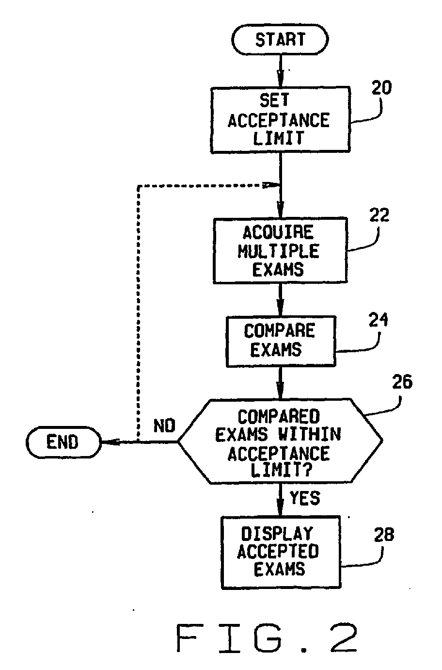
- Fig. 2 shows a preferred method and operation of system 10 for determining if eye exams taken of a patient's eye are acceptable.
- Fig. 2 begins with step 20 where an acceptance limit is set.
- an acceptance limit is set.
- a topographer such as an ORBSCAN System
- the acceptance limit should be set in the range of about 3 microns within the central optic zone. This range is simply an estimate.
- Step 22 acquires multiple exams, which may be as few as two exams of a patient's eye.
- the exams of the patient's eye are a measure of at least some aspect of a patient's vision and in the case of the preferred ORBSCAN System are a representation of at least the anterior corneal surface of the patient's eye. Said another way, the exam is a measure of the topography of an anterior surface of a patient's cornea.
- the eye exam device 12 may perform significant other measurements and exams of the eye beyond the topography of the patient's anterior corneal surface as is true with the preferred ORBSCAN System. These other measurements of the device 12 may be put on hold until an acceptable exam pair is found using the present invention or the physician chooses a particular exam. This can reduce the amount of computation time required of the device 12 to produce a full exam of a patient's eye. At this point, the acquired multiple exams are preferably stored in the memory of device 12.
- step 24 compares the acquired exams.
- Step 24 is described in detail below at Fig. 3.
- step 24 uses a simplex algorithm of the type disclosed in Numerical Recipes in C: The Art of Scientific Computing, by William H. Press, et al.., published by Cambridge University Press, 1992. Numerous other algorithms could also be used such as Random Walk, or brute force, trial and error methods.
- Step 26 determines if the compared exams are within the acceptance limit. If the compared exams are not within the acceptance limit the algorithm can then end or loop back to step 22 to reacquire new exams, as indicated by the dashed line in Fig. 2.
- the accepted exams are preferably displayed on display 14 at step 28 for the physician to choose which exam to use.
- Step 24 for comparing the exams is shown in detail in Fig. 3. Step 24 will be described in detail with respect to exams obtained from the preferred ORBSCAN System, which measures a topography of at least the anterior surface of a patient's cornea. It is to be understood that other algorithms for comparing the eye exams may be used depending upon the type of eye exam device 12 that is being used by the physician. Topography of a patient's cornea that is obtained by the preferred ORBSCAN System is a three-dimensional map of the elevation of the anterior surface of the cornea.
- Step 30 initializes a vector offset, V, as a zero length three-dimensional vector.
- Vector V will be modified and used to offset one exam from another so that they may be compared.
- Step 32 then holds one exam stationary and step 34 offsets the next exam by vector V, which is initially a zero length three-dimensional vector.
- Step 36 subtracts one exam from the other on a point-by-point basis at several points along the surface.
- step 38 produces an array of differences from the results of step 36.
- Step 40 calculates the standard deviation of the array of step 38.
- Next step 42 modifies vector offset V.
- V is modified by the selected algorithm such that a rapid solution is determined as described in Step 44.
- Step 44 determines if a minimum standard deviation has been determined. If a minimum standard deviation has not been determined the process loops back to step 32.
- a minimum standard deviation is preferably determined by the selected algorithm. Preferably, the algorithm efficiently retains the minimum standard deviation and its associated offset vector V, and determines a new V to search for a lower standard deviation.
- step 46 determines if all exam pairs have been compared. If exam pairs remain to be compared, step 48 obtains the next exam pair before proceeding back to step 32. If all exam pairs have been compared the process goes to step 28 for displaying the accepted exams. As previously stated, the accepted exams displayed could be all accepted exams or only the exam pair with a lowest minimum standard deviation. The exam pair with the lowest minimum standard deviation could be said to be the best and most accurate exam pair.
- Fig. 4 discloses an alternate embodiment in accordance with the present invention where, at step 50, device 12 acquires at least three exams and then step 24 compares the acquired exams as described above in Fig. 3. Step 28 then displays the accepted exams, which are preferably the exam pair with a lowest minimum standard deviation.
Landscapes
- Life Sciences & Earth Sciences (AREA)
- Health & Medical Sciences (AREA)
- Medical Informatics (AREA)
- Biophysics (AREA)
- Ophthalmology & Optometry (AREA)
- Engineering & Computer Science (AREA)
- Biomedical Technology (AREA)
- Heart & Thoracic Surgery (AREA)
- Physics & Mathematics (AREA)
- Molecular Biology (AREA)
- Surgery (AREA)
- Animal Behavior & Ethology (AREA)
- General Health & Medical Sciences (AREA)
- Public Health (AREA)
- Veterinary Medicine (AREA)
- Eye Examination Apparatus (AREA)
- Ultra Sonic Daignosis Equipment (AREA)
Abstract
Description
- The present invention relates to assuring a physician that acceptable eye exams have been acquired. More specifically, the present invention relates to assuring acceptable eye topography exams have been acquired by comparing multiple exams.
- Various corneal topography systems and methods are well known and described in the patented arts and in publications, such as Corneal Topography: The State of the Art by Gills, et al., published by Slack, Inc. (1995). The various systems and methods all provide a physician with information concerning a patient's vision defects. A variety of new topography systems, pachymetry systems, wavefront sensors, and general refractive error detection systems can detect the amount of myopia, hyperopia, and astigmatism, and also, higher order aberrations of the refractive characteristics of the eye.
- This vision defect data, assists the physician in determining a patient's vision aberrations and the patient's need for and amount of vision correction. The range of vision correction options includes eyeglasses, contact lenses, or intraocular lenses, and various forms of refractive surgery. Refractive surgery techniques include LASIK (Laser-Assisted In-Situ Keratomileusis), PRK (photorefractive keratectomy), ALK (automated lamellar keratectomy), and LTK (laser thermal keratoplasty). All of these techniques aim to provide permanent vision correction.
- In the event a LASIK procedure is desired, a physician or more likely a laser system develops an ablation profile for each patient's eye. The ablation profile defines the amount and location of corneal tissue to be removed from the patient's eye by the laser system. Laser surgical treatments have become progressively more refined, allowing more subtle defects to be corrected. Myopia and hyperopia can now be corrected to a high degree of precision with current techniques, and using excimer lasers, higher order defects can also be corrected, such as irregular astigmatism.
- With the advance of refractive surgery, a fast developing area is what could properly be called "customized ablation". Customized ablation is where a LASIK or other refractive procedure is performed based upon an ablation profile generated for each individual patient's vision defects. It is believed that this customized ablation will result in better results for the patient than have been known in the prior art and will also significantly reduce the number of poor results. An example of a system employing a topography system in conjunction with a laser to generate an ablation profile is described in U.S. Patent 5,891,132, entitled Distributed Excimer Laser Surgery System, issued 6 April 1999.
- The accuracy of prior art exams has been determined by visual inspection of one or more exam by a physician. Another tool used in the prior art to assist the physician in choosing an exam to use is a difference map. A difference map is a graphical map showing the difference between to exams. The physician can then look at each individual exam and the difference maps to determine what exam, if any, to use for further treatment.
- In preparing these customized ablation profiles, the topography data and other vision defect data will be heavily relied upon. Therefore, a need exists to assure that the data relied upon are accurate.
-
- Fig. 1 is a block diagram of a system in accordance with the present invention;
- Fig. 2 is a flow diagram in accordance with a preferred embodiment of the present invention;
- Fig. 3 is a flow diagram of a portion of Fig. 2 and Fig. 4; and
- Fig. 4 is a flow diagram in accordance with an alternate embodiment of the present invention.
-
- Fig. 1 shows an
eye exam system 10, in accordance with the present invention. Thesystem 10 includes aneye exam device 12 and adisplay 14 for displaying data and graphical representations of an eye exam such as 16 and 18. -
Eye exam device 12 is preferably an eye topography device such as an ORBSCAN® System available from Bausch & Lomb Surgical, Inc., though other known eye topography systems or other eye exam devices known in the art could be used. For example,device 12 could also be a curvature-based topography system, pachymetry system, wavefront sensor, or other vision error detection system, all of which are well known in the art. For illustrative descriptions of the elevation-based ORBSCAN topography system, see U.S. Patents 5,512,965 and 5,512,966 by Richard K. Snook. Whateverspecific device 12 is used it is important that the acquisition of acceptable, accurate exams is assured. As described in detail below, the present invention provides the assurance that more accurate and acceptable exams are used in treating a patient's eye. -
Device 12 also preferably includes a memory (not shown) for acquiring and storing multiple eye exams. Thedisplay 14 may be any commonly known display suitable for graphics and text.Eye exams eye exam exams display 14. - Eye exam device or
eye evaluation system 12 also preferably includes an algorithm for comparing the exams to determine if the exams are acceptable. Because these exams are to be used to treat and correct a patient's vision, particularly where the exams are used to create a customized ablation profile, it is obvious that the physician needs to be confident that the exams are accurate and acceptable. - The preferred algorithms for comparing the exams will be discussed in relation to Figs. 2-4 below. There are essentially two preferred methods where one method can be used with or without a defined acceptance limit.
- More specifically, one preferred method described in detail below at Fig. 2 involves
eye exam device 12 acquiring two exams. These two exams are then compared against each other and if the exams are within a predetermined acceptance limit the exams are accepted and then preferably displayed ondisplay 14. The physician then chooses which exam to use to further treat the patient, such as for developing an ablation profile. - If the two exams are not within the predetermined acceptance limit, a message such as described above is preferably displayed, indicating that new exams need to be acquired. If the two exams are within the acceptance limit both exams can be said to be acceptable and accurate because the odds of two poor and inaccurate exams being within the acceptance limit would be so low as to be statistically insignificant. The acceptance limit is preferably obtained through the acquisition of a statistically significant number of eye exams and is determined by a number of factors such as the comparison of the exam deviation, comparison of results between similar devices, and the resulting patient outcomes.
- If more than two exams are acquired the preferred algorithm for comparing the exams may be used with or without an acceptance limit. If three or more exams are acquired, preferably each exam is compared against each of the other exams. So, for example, when three exams are acquired three comparisons will be made between the first and second exam, the first and third exam, and the second and third exam. If four exams are acquired there would be six comparisons, and if five exams are acquired there would be ten comparisons and so on. If an acceptance limit is used then all exam pairs within the set limit may be displayed to the physician or preferably only the exam pair with a minimum deviation would be displayed. Where three or more exams are acquired and an acceptance limit is not used, preferably the two exams with the lowest minimum deviation are displayed to the physician. The physician then needs to review the exams to determine which exam, if any, to use for further treatment.
- Fig. 2 shows a preferred method and operation of
system 10 for determining if eye exams taken of a patient's eye are acceptable. Fig. 2 begins withstep 20 where an acceptance limit is set. At present, it is believed that if a topographer such as an ORBSCAN System is used asexam device 12, that the acceptance limit should be set in the range of about 3 microns within the central optic zone. This range is simply an estimate. To achieve an accurate acceptance limit evaluation of test data for a particular type ofexam device 12 will need to gathered and evaluated.Step 22 then acquires multiple exams, which may be as few as two exams of a patient's eye. The exams of the patient's eye are a measure of at least some aspect of a patient's vision and in the case of the preferred ORBSCAN System are a representation of at least the anterior corneal surface of the patient's eye. Said another way, the exam is a measure of the topography of an anterior surface of a patient's cornea. Theeye exam device 12 may perform significant other measurements and exams of the eye beyond the topography of the patient's anterior corneal surface as is true with the preferred ORBSCAN System. These other measurements of thedevice 12 may be put on hold until an acceptable exam pair is found using the present invention or the physician chooses a particular exam. This can reduce the amount of computation time required of thedevice 12 to produce a full exam of a patient's eye. At this point, the acquired multiple exams are preferably stored in the memory ofdevice 12. - Next,
step 24 compares the acquired exams.Step 24 is described in detail below at Fig. 3. Preferably, step 24 uses a simplex algorithm of the type disclosed in Numerical Recipes in C: The Art of Scientific Computing, by William H. Press, et al.., published by Cambridge University Press, 1992. Numerous other algorithms could also be used such as Random Walk, or brute force, trial and error methods.Step 26 then determines if the compared exams are within the acceptance limit. If the compared exams are not within the acceptance limit the algorithm can then end or loop back to step 22 to reacquire new exams, as indicated by the dashed line in Fig. 2. - If the compared exams are within the acceptance limit the accepted exams are preferably displayed on
display 14 atstep 28 for the physician to choose which exam to use. -
Step 24 for comparing the exams is shown in detail in Fig. 3.Step 24 will be described in detail with respect to exams obtained from the preferred ORBSCAN System, which measures a topography of at least the anterior surface of a patient's cornea. It is to be understood that other algorithms for comparing the eye exams may be used depending upon the type ofeye exam device 12 that is being used by the physician. Topography of a patient's cornea that is obtained by the preferred ORBSCAN System is a three-dimensional map of the elevation of the anterior surface of the cornea. -
Step 30 initializes a vector offset, V, as a zero length three-dimensional vector. Vector V will be modified and used to offset one exam from another so that they may be compared.Step 32 then holds one exam stationary and step 34 offsets the next exam by vector V, which is initially a zero length three-dimensional vector.Step 36 subtracts one exam from the other on a point-by-point basis at several points along the surface. Next,step 38 produces an array of differences from the results ofstep 36. -
Step 40 calculates the standard deviation of the array ofstep 38.Next step 42 modifies vector offset V. Preferably, V is modified by the selected algorithm such that a rapid solution is determined as described inStep 44. -
Step 44 then determines if a minimum standard deviation has been determined. If a minimum standard deviation has not been determined the process loops back to step 32. A minimum standard deviation is preferably determined by the selected algorithm. Preferably, the algorithm efficiently retains the minimum standard deviation and its associated offset vector V, and determines a new V to search for a lower standard deviation. - If a minimum standard deviation has been determined for a pair of exams, step 46 then determines if all exam pairs have been compared. If exam pairs remain to be compared,
step 48 obtains the next exam pair before proceeding back to step 32. If all exam pairs have been compared the process goes to step 28 for displaying the accepted exams. As previously stated, the accepted exams displayed could be all accepted exams or only the exam pair with a lowest minimum standard deviation. The exam pair with the lowest minimum standard deviation could be said to be the best and most accurate exam pair. - Fig. 4 discloses an alternate embodiment in accordance with the present invention where, at
step 50,device 12 acquires at least three exams and then step 24 compares the acquired exams as described above in Fig. 3.Step 28 then displays the accepted exams, which are preferably the exam pair with a lowest minimum standard deviation. - Thus, there has been shown and described an inventive eye evaluation system and method for assuring that acceptable and accurate eye exams have been obtained. Other embodiments of the present invention may fall within the scope of the claims, as will be readily apparent by those skilled in the art.
Claims (8)
- A method of accepting eye topography exams, for use by a physician in treating a patient's eye, comprising the steps of:acquiring at least three exams of the patient's eye wherein each exam is at least a measure of a topography of an anterior surface of a patient's cornea;comparing each exam with the other exams to produce a comparison result for each exam pair; andaccepting the exam pair having the comparison result indicating that the accepted exam pair are most similar to each other relative to the other exam pairs.
- A method as claimed in Claim 1 further including the step of displaying the accepted exam pair for use by the physician.
- A method as claimed in Claim 1 or Claim 2 in which the acquiring step further includes the steps of:using an eye topography device, such as an ORBSCAN System, for acquiring the exams; andstoring each exam in a memory of the device.
- A method as claimed in any preceding claim which comprises comparing each exam with the other exams to produce minimum standard deviation for each exam pair; and
accepting the exam pair with the lowest standard deviation. - A method as claimed in any preceding claim in which the comparing step further includes the steps of:(a) offsetting each exam relative to the other exams by a three-dimensional vector;(b) subtracting each exam for the other exams at several points on the anterior surface to produce an array of differences;(c) calculating a standard deviation of the array; and(d) repeating steps (a) to (c) to determine a minimum standard deviation for each pair of exams.
- A method as claimed in any one of Claims 1 to 4 in which the comparing step further includes the steps of:(a) offsetting each exam relative to the other exams by a three-dimensional vector;(b) subtracting each exam from the other exams at several points on the anterior surface to produce an array of differences for each exam pair;(c) calculating a standard deviation of the array;(d) modifying the three-dimensional vector; and(e) repeating steps (a) to (d) until a minimum standard deviation for each exam pair is determined.
- A method as claimed in any preceding claim in which the accepting step further includes accepting the exam pair with the lowest minimum standard deviation.
- A method as claimed in Claim 7 in which the accepting step still further includes accepting the lowest minimum standard deviation exam pair whose minimum standard deviation is less than or equal to a predetermined acceptable standard deviation.
Applications Claiming Priority (3)
| Application Number | Priority Date | Filing Date | Title |
|---|---|---|---|
| US09/534,095 US6402319B1 (en) | 2000-03-23 | 2000-03-23 | Acquisition of multiple eye topography exams |
| US534095 | 2000-03-23 | ||
| EP01920626A EP1265523B1 (en) | 2000-03-23 | 2001-03-21 | Acquisition of multiple eye topography exams |
Related Parent Applications (2)
| Application Number | Title | Priority Date | Filing Date |
|---|---|---|---|
| EP01920626.7 Division | 2001-03-21 | ||
| EP01920626A Division EP1265523B1 (en) | 2000-03-23 | 2001-03-21 | Acquisition of multiple eye topography exams |
Publications (3)
| Publication Number | Publication Date |
|---|---|
| EP1488733A2 true EP1488733A2 (en) | 2004-12-22 |
| EP1488733A3 EP1488733A3 (en) | 2005-08-17 |
| EP1488733B1 EP1488733B1 (en) | 2012-11-21 |
Family
ID=24128682
Family Applications (2)
| Application Number | Title | Priority Date | Filing Date |
|---|---|---|---|
| EP04018672A Expired - Lifetime EP1488733B1 (en) | 2000-03-23 | 2001-03-21 | Acquisition of multiple eye topography exams |
| EP01920626A Expired - Lifetime EP1265523B1 (en) | 2000-03-23 | 2001-03-21 | Acquisition of multiple eye topography exams |
Family Applications After (1)
| Application Number | Title | Priority Date | Filing Date |
|---|---|---|---|
| EP01920626A Expired - Lifetime EP1265523B1 (en) | 2000-03-23 | 2001-03-21 | Acquisition of multiple eye topography exams |
Country Status (9)
| Country | Link |
|---|---|
| US (1) | US6402319B1 (en) |
| EP (2) | EP1488733B1 (en) |
| JP (1) | JP4790188B2 (en) |
| CN (1) | CN100398055C (en) |
| AU (2) | AU2001247659B2 (en) |
| CA (1) | CA2403510C (en) |
| DE (1) | DE60129415T2 (en) |
| ES (2) | ES2396968T3 (en) |
| WO (1) | WO2001070099A2 (en) |
Cited By (1)
| Publication number | Priority date | Publication date | Assignee | Title |
|---|---|---|---|---|
| US9839352B2 (en) | 2015-08-15 | 2017-12-12 | Smart EyeDeas I, LLC | System, method and apparatus for enabling corneal topography mapping by smartphone |
Families Citing this family (2)
| Publication number | Priority date | Publication date | Assignee | Title |
|---|---|---|---|---|
| EP2092876B1 (en) * | 1999-10-21 | 2012-08-01 | Technolas Perfect Vision GmbH | Customized Corneal Profiling |
| US7226443B1 (en) * | 2003-11-07 | 2007-06-05 | Alcon Refractivehorizons, Inc. | Optimization of ablation correction of an optical system and associated methods |
Citations (1)
| Publication number | Priority date | Publication date | Assignee | Title |
|---|---|---|---|---|
| US4705037A (en) | 1985-02-08 | 1987-11-10 | Peyman Gholam A | Topographical mapping, depth measurement, and cutting systems for performing radial keratotomy and the like |
Family Cites Families (13)
| Publication number | Priority date | Publication date | Assignee | Title |
|---|---|---|---|---|
| US4019813A (en) * | 1976-01-19 | 1977-04-26 | Baylor College Of Medicine | Optical apparatus for obtaining measurements of portions of the eye |
| US4420228A (en) * | 1980-06-12 | 1983-12-13 | Humphrey Instruments, Inc. | Method and apparatus for analysis of corneal shape |
| JPS6377432A (en) * | 1986-09-20 | 1988-04-07 | キヤノン株式会社 | Ophthalmic imaging apparatus |
| US5307097A (en) * | 1992-11-05 | 1994-04-26 | Kera-Metrics, Inc. | Corneal topography system including single-direction shearing of holograph grating in orthogonal directions |
| AU716040B2 (en) | 1993-06-24 | 2000-02-17 | Bausch & Lomb Incorporated | Ophthalmic pachymeter and method of making ophthalmic determinations |
| JPH10507953A (en) * | 1994-10-28 | 1998-08-04 | アイシーズ、テクノロジーズ、インコーポレーテッド | Corneal analyzer for compound camera |
| JP3509377B2 (en) * | 1996-04-12 | 2004-03-22 | 株式会社ニコン | Curvature measuring device |
| US5891132A (en) | 1996-05-30 | 1999-04-06 | Chiron Technolas Gmbh Opthalmologische Systeme | Distributed excimer laser surgery system |
| US5907388A (en) * | 1996-10-03 | 1999-05-25 | Nidek Co., Ltd. | Ophthalmic measurement apparatus having plural pairs of photoreceiving elements |
| IL132123A0 (en) * | 1997-04-01 | 2001-03-19 | Univ Johns Hopkins | A system for imaging an ocular fundus semi-automatically at high resolution and wide field |
| JP4003323B2 (en) * | 1997-12-09 | 2007-11-07 | 株式会社ニコン | Objective measurement device |
| JP2000070223A (en) * | 1998-08-31 | 2000-03-07 | Nikon Corp | Objective measuring device |
| JP2000325311A (en) * | 1999-05-25 | 2000-11-28 | Nikon Corp | Objective measurement device |
-
2000
- 2000-03-23 US US09/534,095 patent/US6402319B1/en not_active Expired - Lifetime
-
2001
- 2001-03-21 ES ES04018672T patent/ES2396968T3/en not_active Expired - Lifetime
- 2001-03-21 CN CNB018070191A patent/CN100398055C/en not_active Expired - Fee Related
- 2001-03-21 AU AU2001247659A patent/AU2001247659B2/en not_active Ceased
- 2001-03-21 AU AU4765901A patent/AU4765901A/en active Pending
- 2001-03-21 EP EP04018672A patent/EP1488733B1/en not_active Expired - Lifetime
- 2001-03-21 CA CA002403510A patent/CA2403510C/en not_active Expired - Fee Related
- 2001-03-21 ES ES01920626T patent/ES2288938T3/en not_active Expired - Lifetime
- 2001-03-21 WO PCT/US2001/009089 patent/WO2001070099A2/en not_active Ceased
- 2001-03-21 JP JP2001568302A patent/JP4790188B2/en not_active Expired - Fee Related
- 2001-03-21 EP EP01920626A patent/EP1265523B1/en not_active Expired - Lifetime
- 2001-03-21 DE DE60129415T patent/DE60129415T2/en not_active Expired - Lifetime
Patent Citations (1)
| Publication number | Priority date | Publication date | Assignee | Title |
|---|---|---|---|---|
| US4705037A (en) | 1985-02-08 | 1987-11-10 | Peyman Gholam A | Topographical mapping, depth measurement, and cutting systems for performing radial keratotomy and the like |
Cited By (1)
| Publication number | Priority date | Publication date | Assignee | Title |
|---|---|---|---|---|
| US9839352B2 (en) | 2015-08-15 | 2017-12-12 | Smart EyeDeas I, LLC | System, method and apparatus for enabling corneal topography mapping by smartphone |
Also Published As
| Publication number | Publication date |
|---|---|
| AU4765901A (en) | 2001-10-03 |
| CA2403510A1 (en) | 2001-09-27 |
| EP1265523B1 (en) | 2007-07-18 |
| JP4790188B2 (en) | 2011-10-12 |
| DE60129415D1 (en) | 2007-08-30 |
| EP1488733B1 (en) | 2012-11-21 |
| WO2001070099A2 (en) | 2001-09-27 |
| US6402319B1 (en) | 2002-06-11 |
| WO2001070099A3 (en) | 2002-06-27 |
| AU2001247659B2 (en) | 2004-11-04 |
| CN100398055C (en) | 2008-07-02 |
| EP1265523A2 (en) | 2002-12-18 |
| JP2003527183A (en) | 2003-09-16 |
| ES2396968T3 (en) | 2013-03-01 |
| CN1431883A (en) | 2003-07-23 |
| CA2403510C (en) | 2007-08-21 |
| EP1488733A3 (en) | 2005-08-17 |
| DE60129415T2 (en) | 2008-04-10 |
| ES2288938T3 (en) | 2008-02-01 |
Similar Documents
| Publication | Publication Date | Title |
|---|---|---|
| US7699468B2 (en) | Ophthalmologic surgical microscope having a measuring unit | |
| US5861955A (en) | Topographical cornea mapping for corneal vision correction | |
| US4669466A (en) | Method and apparatus for analysis and correction of abnormal refractive errors of the eye | |
| Mrochen et al. | Increased higher-order optical aberrations after laser refractive surgery: a problem of subclinical decentration | |
| US6554429B1 (en) | Method for determining accommodation | |
| KR101552297B1 (en) | Device and method for a laser-assisted eye surgery treatment system | |
| Maloney et al. | Determination of corneal image-forming properties from corneal topography | |
| US8708488B2 (en) | Eye surgery system and methods of preparing and performing an eye surgery | |
| CN101065053B (en) | Method to prevent the introduction of aberrations in laser refractive surgery systems | |
| US6394605B1 (en) | Fogging method for a wavefront sensor | |
| US20080249514A1 (en) | Method and Apparatus for Multi-Step Correction of Ophthalmic Refractive Errors | |
| WO1997043006A1 (en) | Simulating corneal laser surgery | |
| EP1265523B1 (en) | Acquisition of multiple eye topography exams | |
| AU2003297692B2 (en) | System and method for evaluating a secondary LASIK treatment | |
| AU2001247659A1 (en) | Acquisition of multiple eye topography exams | |
| JP4478434B2 (en) | Ophthalmic surgery simulation method | |
| Bende et al. | Optical transfer function in corneal topography for clinical contrast sensitivity analysis | |
| KR930005583B1 (en) | Ophthalmic devices |
Legal Events
| Date | Code | Title | Description |
|---|---|---|---|
| PUAI | Public reference made under article 153(3) epc to a published international application that has entered the european phase |
Free format text: ORIGINAL CODE: 0009012 |
|
| 17P | Request for examination filed |
Effective date: 20040806 |
|
| AC | Divisional application: reference to earlier application |
Ref document number: 1265523 Country of ref document: EP Kind code of ref document: P |
|
| AK | Designated contracting states |
Kind code of ref document: A2 Designated state(s): AT BE CH CY DE ES FR GB IT LI |
|
| PUAL | Search report despatched |
Free format text: ORIGINAL CODE: 0009013 |
|
| AK | Designated contracting states |
Kind code of ref document: A3 Designated state(s): AT BE CH CY DE ES FR GB IT LI |
|
| RIC1 | Information provided on ipc code assigned before grant |
Ipc: 7A 61B 3/00 A Ipc: 7A 61B 8/10 B Ipc: 7A 61B 3/107 B |
|
| AKX | Designation fees paid |
Designated state(s): DE ES FR GB IT |
|
| 17Q | First examination report despatched |
Effective date: 20111121 |
|
| GRAP | Despatch of communication of intention to grant a patent |
Free format text: ORIGINAL CODE: EPIDOSNIGR1 |
|
| GRAS | Grant fee paid |
Free format text: ORIGINAL CODE: EPIDOSNIGR3 |
|
| GRAA | (expected) grant |
Free format text: ORIGINAL CODE: 0009210 |
|
| AC | Divisional application: reference to earlier application |
Ref document number: 1265523 Country of ref document: EP Kind code of ref document: P |
|
| AK | Designated contracting states |
Kind code of ref document: B1 Designated state(s): DE ES FR GB IT |
|
| REG | Reference to a national code |
Ref country code: GB Ref legal event code: FG4D |
|
| REG | Reference to a national code |
Ref country code: DE Ref legal event code: R096 Ref document number: 60147414 Country of ref document: DE Effective date: 20130110 |
|
| REG | Reference to a national code |
Ref country code: ES Ref legal event code: FG2A Ref document number: 2396968 Country of ref document: ES Kind code of ref document: T3 Effective date: 20130301 |
|
| PLBE | No opposition filed within time limit |
Free format text: ORIGINAL CODE: 0009261 |
|
| STAA | Information on the status of an ep patent application or granted ep patent |
Free format text: STATUS: NO OPPOSITION FILED WITHIN TIME LIMIT |
|
| 26N | No opposition filed |
Effective date: 20130822 |
|
| REG | Reference to a national code |
Ref country code: DE Ref legal event code: R097 Ref document number: 60147414 Country of ref document: DE Effective date: 20130822 |
|
| REG | Reference to a national code |
Ref country code: FR Ref legal event code: PLFP Year of fee payment: 16 |
|
| REG | Reference to a national code |
Ref country code: FR Ref legal event code: PLFP Year of fee payment: 17 |
|
| REG | Reference to a national code |
Ref country code: FR Ref legal event code: PLFP Year of fee payment: 18 |
|
| PGFP | Annual fee paid to national office [announced via postgrant information from national office to epo] |
Ref country code: GB Payment date: 20180223 Year of fee payment: 18 Ref country code: DE Payment date: 20180308 Year of fee payment: 18 |
|
| PGFP | Annual fee paid to national office [announced via postgrant information from national office to epo] |
Ref country code: IT Payment date: 20180315 Year of fee payment: 18 Ref country code: FR Payment date: 20180223 Year of fee payment: 18 |
|
| PGFP | Annual fee paid to national office [announced via postgrant information from national office to epo] |
Ref country code: ES Payment date: 20180403 Year of fee payment: 18 |
|
| REG | Reference to a national code |
Ref country code: DE Ref legal event code: R119 Ref document number: 60147414 Country of ref document: DE |
|
| GBPC | Gb: european patent ceased through non-payment of renewal fee |
Effective date: 20190321 |
|
| PG25 | Lapsed in a contracting state [announced via postgrant information from national office to epo] |
Ref country code: GB Free format text: LAPSE BECAUSE OF NON-PAYMENT OF DUE FEES Effective date: 20190321 Ref country code: DE Free format text: LAPSE BECAUSE OF NON-PAYMENT OF DUE FEES Effective date: 20191001 |
|
| PG25 | Lapsed in a contracting state [announced via postgrant information from national office to epo] |
Ref country code: IT Free format text: LAPSE BECAUSE OF NON-PAYMENT OF DUE FEES Effective date: 20190321 Ref country code: FR Free format text: LAPSE BECAUSE OF NON-PAYMENT OF DUE FEES Effective date: 20190331 |
|
| REG | Reference to a national code |
Ref country code: ES Ref legal event code: FD2A Effective date: 20200728 |
|
| PG25 | Lapsed in a contracting state [announced via postgrant information from national office to epo] |
Ref country code: ES Free format text: LAPSE BECAUSE OF NON-PAYMENT OF DUE FEES Effective date: 20190322 |