EP1487665B1 - Manually operated ramp assembly - Google Patents
Manually operated ramp assembly Download PDFInfo
- Publication number
- EP1487665B1 EP1487665B1 EP03715107A EP03715107A EP1487665B1 EP 1487665 B1 EP1487665 B1 EP 1487665B1 EP 03715107 A EP03715107 A EP 03715107A EP 03715107 A EP03715107 A EP 03715107A EP 1487665 B1 EP1487665 B1 EP 1487665B1
- Authority
- EP
- European Patent Office
- Prior art keywords
- platform
- ramp assembly
- manually operated
- ramp
- stowed
- Prior art date
- Legal status (The legal status is an assumption and is not a legal conclusion. Google has not performed a legal analysis and makes no representation as to the accuracy of the status listed.)
- Expired - Lifetime
Links
Images


Classifications
-
- B—PERFORMING OPERATIONS; TRANSPORTING
- B60—VEHICLES IN GENERAL
- B60P—VEHICLES ADAPTED FOR LOAD TRANSPORTATION OR TO TRANSPORT, TO CARRY, OR TO COMPRISE SPECIAL LOADS OR OBJECTS
- B60P1/00—Vehicles predominantly for transporting loads and modified to facilitate loading, consolidating the load, or unloading
- B60P1/43—Vehicles predominantly for transporting loads and modified to facilitate loading, consolidating the load, or unloading using a loading ramp mounted on the vehicle
- B60P1/433—Vehicles predominantly for transporting loads and modified to facilitate loading, consolidating the load, or unloading using a loading ramp mounted on the vehicle the loading floor or a part thereof being movable to form the ramp
-
- A—HUMAN NECESSITIES
- A61—MEDICAL OR VETERINARY SCIENCE; HYGIENE
- A61G—TRANSPORT, PERSONAL CONVEYANCES, OR ACCOMMODATION SPECIALLY ADAPTED FOR PATIENTS OR DISABLED PERSONS; OPERATING TABLES OR CHAIRS; CHAIRS FOR DENTISTRY; FUNERAL DEVICES
- A61G3/00—Ambulance aspects of vehicles; Vehicles with special provisions for transporting patients or disabled persons, or their personal conveyances, e.g. for facilitating access of, or for loading, wheelchairs
- A61G3/02—Loading or unloading personal conveyances; Facilitating access of patients or disabled persons to, or exit from, vehicles
- A61G3/06—Transfer using ramps, lifts or the like
- A61G3/061—Transfer using ramps, lifts or the like using ramps
-
- A—HUMAN NECESSITIES
- A61—MEDICAL OR VETERINARY SCIENCE; HYGIENE
- A61G—TRANSPORT, PERSONAL CONVEYANCES, OR ACCOMMODATION SPECIALLY ADAPTED FOR PATIENTS OR DISABLED PERSONS; OPERATING TABLES OR CHAIRS; CHAIRS FOR DENTISTRY; FUNERAL DEVICES
- A61G3/00—Ambulance aspects of vehicles; Vehicles with special provisions for transporting patients or disabled persons, or their personal conveyances, e.g. for facilitating access of, or for loading, wheelchairs
- A61G3/02—Loading or unloading personal conveyances; Facilitating access of patients or disabled persons to, or exit from, vehicles
- A61G3/06—Transfer using ramps, lifts or the like
- A61G3/067—Transfer using ramps, lifts or the like with compartment for horizontally storing the ramp or lift
Definitions
- the present invention relates in general to a manually operated ramp assembly and more particularly a ramp assembly for use primarily with either a public access vehicle or a public building.
- a ramp assembly representing the features of the preamble of claim 1 is known from GB 2 301 082 A.
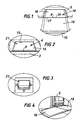
- FIG. 1-5 A further known type of manually operated 'book leaf' ramp assembly 10 and the method of operating the assembly is shown in Figures 1-5 and Figure 11.
- a ramp assembly is typically attached within the access step of a public access vehicle 5 as may be seen in Figure 4.
- the ramp assembly 10 is composed of first and second plate-like platforms 18, 16 pivotably interconnected with a hinge 9 attached to a first outer end region 19 of the first platform 18 and an adjacent second inner end region 17 of the second platform 16.
- the first or innermost platform 18 remains stationary and can be inset into a floor of the vehicle 5 while the second or outermost platform 16 is moved.
- the platforms 16, 18 can be stowed one on the other or deployed to create a ramp for easier access to a vehicle 5 (Figure 5).
- the first platform 18 is normally fitted below the level of the floor of the vehicle to which it is attached so that in the stowed position the ramp assembly 10 forms an integral unit of the floor to which it is secured. When in the stowed position the ramp assembly 10 latches and locks into position and is retained during transit.
- An end region 15 of the movable platform 16 remote from the hinge 9 is provided with a lifting and locking mechanism 21 accessible when the ramp assembly is stowed.
- the mechanism 21 can be released by manual operation and presents a lifting ring which enables an operator to raise the platform 16 and swing it around the hinge 9 into the deployed position ( Figure 4). In the deployed position the mechanism 21 lies on the underside of the ramp 18, 16.
- the assembly has the locking and lifting mechanism 21 positioned some considerable distance from the step edge ( Figure 4).
- the locking and lifting mechanism 21 is positioned some 550 mm from the step edge 3 to inside the vehicle.
- an operator 6 has to lean inside the vehicle and reach for the locking and lifting mechanism 21 some +500 mm from the step edge in order to extend the ramp. In doing so the operator will be in the worst possible posture and liable to personal injury (see Figure 5). Also since this posture is induced, the operator will be able to lift comparatively very little as is indicated by Figure 5.
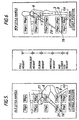
- Figures 5 and 11 illustrate clearly the increased possibility of injury being caused to the operator 6 as a direct result of the poor design of the ramp assembly.
- the positioning of the lifting ring of the locking and lifting mechanism 21, as can be seen in Figure 5, is responsible for the poor posture of the body.
- Figure 5 indicates recommended maximum weights corresponding to different positions of the hands. It can be seen in Figure 5 that the maximum weight is supported by the back 11 of the operator 6 whilst in a bent position - the probability of injury is thus higher.
- Figure 11 when stowing the ramp from the deployed position it is again necessary to bear the load of the ramp on the back 11 of the operator 6 whilst maintaining a posture that could lead to further personal injury.
- the poor posture that the current ramp assemblies induce and the increased stress that they place upon the body it may be seen from both Figures 5 and 11 that neither the deployment nor re-deployrnent of the ramp assembly could be executed by a disabled person.
- the driver of the vehicle 5 is usually responsible for operating the ramp assembly. In order to do so therefore he will be forced to leave the driving area and cash box unattended whilst he extends the ramp assembly as well as causing possible injury to himself for the reasons described above.
- a manually operated ramp assembly comprising: at least two platforms pivotably interconnected at adjacent end regions and capable of being stowed or extended wherein in the stowed position the second platform lies above the first platform and in the extended position the second platform extends in front of and below the first platform to form a smooth gradient and a ramp extension facility consisting of a link, e.g., a pivotable operating lever, attached to an end region of the second platform remote from the pivotably connected region and having a handle which can be accessed from the pivotably connected region of the second platform when the platforms are stowed.
- a link e.g., a pivotable operating lever
- the invention provides a ramp assembly composed of articulated platforms capable of extending to form a ramp or being stowed one above the other and an articulated link which can be manually operated to bring the platforms into the stowed or extended positions.
- the link has a handle and the link can itself be stowed in a recess alongside the platforms when the platforms are stowed.
- An operator can grasp the handle which in the stowed position presents itself near the outwardly facing pivot joint between the platforms and then the link can be manipulated to swing the uppermost platform outwardly to the extended position.
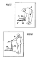
- FIG 7 illustrates a modified ramp assembly 10 constructed according to the present invention in the stowed position wherein like reference numerals denote like parts to Figures 1-4.
- the ramp assembly 10 when extended is illustrated in Figure 10.
- the first platform 18 is secured to a base or floor on a public access vehicle or a public building whilst the second platform 16 unfolds relative to the first platform and lies in front of and below the first platform 18 (see Figure 10).
- the first and second platforms 16, 18 are pivotably attached at adjacent first end regions 19, 17 with the hinge 9.
- the ramp assembly 10 is provided with a ramp extension facility designed to increase the load bearing capacity of the operator 6 and to maintain the best possible posture to avoid injury to the operator 6 whilst extending the ramp assembly 10.
- the ramp extension facility consists of an operating link, illustrated as a lever 20, pivotably attached with a pivot joint 2 to one side of the second platform 16 of the ramp assembly near the end region 15.
- the lever 20 has a length almost as large as one of the platforms 16, 18 in the direction of their deployment, i.e. the ramp.
- a handle 22 for gripping At the end of the lever 20 remote from the pivot 2 there is a handle 22 for gripping.
- the handle 22 of the operating lever 20 is disposed adjacent to the hinged end region 17 of the platform 16.
- the pivot joint 2 linking the lever 20 to the platform 16 can be located in a similar position to the mechanism 21 in the prior art construction.
- the operator manoeuvres the operating lever 20 upwards and outwards to raise and extend the second platform 16 towards him.
- the second platform 16 is pulled upwards and outwards and then lowered to the floor in front of the operator 6 to extend the ramp assembly ( Figure 10).
- the operating lever 20 can be latched and stored alongside the ramp assembly.
- the handle 22 of the operating lever 20 lays next to the hinge 9 that connects the first and second platforms 18, 16.
- the link may be in the form of a cable or chain, either having a handle 22.
- a ramp assembly constructed in accordance with the present invention thus has the advantage over the state of the art in that it can be operated from a location which is convenient to the operator 6. It is not necessary for the user to change hands when deploying and stowing the ramp assembly as this can all be done in one continuous motion. The operator 6 therefore saves time and ensures greater safety. The driver of a public access vehicle does not therefore have to leave the driving area unattended to operate the ramp assembly. As a result of the lifting mechanism and use of the operating lever 20 the ramp assembly may be activated by a disabled person since the maximum force required to extend the ramp is limited to 6 kg.
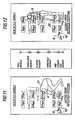
- lever 20 is shown to be located at the lefthand side of the ramp assembly 10 relative to the operator.
- Figure 13 shows another embodiment in which the lever 20 is located at the right-hand side.
- a box-like housing 25 is fixed to the side of the platform 16 and accommodates the lever 20.
- the box 25 is partially closed by a fixed part cover 26 at one end.
- the lever 20 has an extension 27 which extends under the part cover 26 to hold the two platforms closed together when the lever 20 is stowed as shown in Figure 13.
- a spring-loaded flap (not shown) can be released to enable an operator to gain access to the handle 22.
- the interaction with the brake interlock switch can be accomplished when the flap is released, for example, by a proximity switch.
- the platforms 16, 18 in the embodiments described are preferably provided with a slip resistant surface and designed to be wheelchair castor friendly.
- the hinge mechanism 9 is made from known material to reduce the rate of corrosion and the major surfaces of the ramp platforms 16, 18 are hot metal sprayed and enamel finished.
- the pivot joint 2 linking the lever 20 to the platform 16 can be in the form of a universal joint to enable the lever 20 to be moved from side to side as well as raised and lowered.
Landscapes
- Health & Medical Sciences (AREA)
- Public Health (AREA)
- Veterinary Medicine (AREA)
- Life Sciences & Earth Sciences (AREA)
- Animal Behavior & Ethology (AREA)
- General Health & Medical Sciences (AREA)
- Engineering & Computer Science (AREA)
- Mechanical Engineering (AREA)
- Transportation (AREA)
- Vehicle Step Arrangements And Article Storage (AREA)
- Domestic Plumbing Installations (AREA)
- Vehicle Body Suspensions (AREA)
- Lock And Its Accessories (AREA)
- Electrophonic Musical Instruments (AREA)
- Mechanical Operated Clutches (AREA)
- Telephone Function (AREA)
- Steering Control In Accordance With Driving Conditions (AREA)
Abstract
Description
- The present invention relates in general to a manually operated ramp assembly and more particularly a ramp assembly for use primarily with either a public access vehicle or a public building. Such a ramp assembly representing the features of the preamble of claim 1 is known from
GB 2 301 082 A. - A further known type of manually operated 'book leaf'
ramp assembly 10 and the method of operating the assembly is shown in Figures 1-5 and Figure 11. Such a ramp assembly is typically attached within the access step of apublic access vehicle 5 as may be seen in Figure 4. Theramp assembly 10 is composed of first and second plate-like platforms hinge 9 attached to a firstouter end region 19 of thefirst platform 18 and an adjacent secondinner end region 17 of thesecond platform 16. The first orinnermost platform 18 remains stationary and can be inset into a floor of thevehicle 5 while the second oroutermost platform 16 is moved. By swinging theplatform 16 about thehinge 9 theplatforms first platform 18 is normally fitted below the level of the floor of the vehicle to which it is attached so that in the stowed position theramp assembly 10 forms an integral unit of the floor to which it is secured. When in the stowed position theramp assembly 10 latches and locks into position and is retained during transit. Anend region 15 of themovable platform 16 remote from thehinge 9 is provided with a lifting andlocking mechanism 21 accessible when the ramp assembly is stowed. Themechanism 21 can be released by manual operation and presents a lifting ring which enables an operator to raise theplatform 16 and swing it around thehinge 9 into the deployed position (Figure 4). In the deployed position themechanism 21 lies on the underside of theramp lifting mechanism 21 positioned some considerable distance from the step edge (Figure 4). Typically, the locking andlifting mechanism 21 is positioned some 550 mm from thestep edge 3 to inside the vehicle. As a result anoperator 6 has to lean inside the vehicle and reach for the locking andlifting mechanism 21 some +500 mm from the step edge in order to extend the ramp. In doing so the operator will be in the worst possible posture and liable to personal injury (see Figure 5). Also since this posture is induced, the operator will be able to lift comparatively very little as is indicated by Figure 5. - According to the current Health and Safety Regulations the ergonomic body diagrams (Figures 5 and 11) illustrate clearly the increased possibility of injury being caused to the
operator 6 as a direct result of the poor design of the ramp assembly. The positioning of the lifting ring of the locking andlifting mechanism 21, as can be seen in Figure 5, is responsible for the poor posture of the body. Figure 5 indicates recommended maximum weights corresponding to different positions of the hands. It can be seen in Figure 5 that the maximum weight is supported by theback 11 of theoperator 6 whilst in a bent position - the probability of injury is thus higher. Similarly in Figure 11 when stowing the ramp from the deployed position it is again necessary to bear the load of the ramp on theback 11 of theoperator 6 whilst maintaining a posture that could lead to further personal injury. As a result of the poor posture that the current ramp assemblies induce and the increased stress that they place upon the body it may be seen from both Figures 5 and 11 that neither the deployment nor re-deployrnent of the ramp assembly could be executed by a disabled person. - Furthermore the driver of the
vehicle 5 is usually responsible for operating the ramp assembly. In order to do so therefore he will be forced to leave the driving area and cash box unattended whilst he extends the ramp assembly as well as causing possible injury to himself for the reasons described above. - It is the aim of the present invention to provide an improved ramp assembly for use in public access vehicles or public buildings to overcome the difficulties herein described.
- According to one aspect of the invention there is provided a manually operated ramp assembly comprising: at least two platforms pivotably interconnected at adjacent end regions and capable of being stowed or extended wherein in the stowed position the second platform lies above the first platform and in the extended position the second platform extends in front of and below the first platform to form a smooth gradient and a ramp extension facility consisting of a link, e.g., a pivotable operating lever, attached to an end region of the second platform remote from the pivotably connected region and having a handle which can be accessed from the pivotably connected region of the second platform when the platforms are stowed.
- In another aspect the invention provides a ramp assembly composed of articulated platforms capable of extending to form a ramp or being stowed one above the other and an articulated link which can be manually operated to bring the platforms into the stowed or extended positions.
- Preferably the link has a handle and the link can itself be stowed in a recess alongside the platforms when the platforms are stowed. An operator can grasp the handle which in the stowed position presents itself near the outwardly facing pivot joint between the platforms and then the link can be manipulated to swing the uppermost platform outwardly to the extended position.
- The invention may be understood more readily, and various other features of the invention may become more apparent, from consideration of the following description.
- Embodiments of the present invention will now be described hereafter in detail, by way of examples only, and with reference to the accompanying drawings, wherein:
- Figure 1 is a front view of a known ramp assembly when extended;
- Figure 2 is a front view of a known ramp assembly when stowed;
- Figure 3 is a plan view of the known locking and latching mechanism;
- Figure 4 is a side view of a known ramp assembly when deployed and attached to public access vehicle;
- Figure 5 is a diagrammatic representation of an operator lifting the known ramp assembly from the stowed position;
- Figure 6 is a diagrammatic representation of an operator lifting a ramp assembly constructed in accordance with the invention from the stowed position;
- Figure 7 is a side view of the ramp assembly shown in Figure 6 at the moment before deployment;
- Figure 8 is a side view of the ramp assembly shown in Figure 6 at its maximum height and weight during deployment;
- Figure 9 is a side view of the ramp assembly shown in Figure 6 in mid-deployment;
- Figure 10 is a side view of the ramp assembly shown in Figure 6 fully deployed;
- Figure 11 is a diagrammatic representation of an operator lifting a known ramp assembly from the deployed position;
- Figure 12 is a diagrammatic representation of an operator lifting the ramp assembly according to the invention from the deployed position; and
- Figure 13 is a plan view of part of another stowed ramp assembly constructed in accordance with the invention.
- Figure 7 illustrates a modified
ramp assembly 10 constructed according to the present invention in the stowed position wherein like reference numerals denote like parts to Figures 1-4. Theramp assembly 10 when extended is illustrated in Figure 10. As before, thefirst platform 18 is secured to a base or floor on a public access vehicle or a public building whilst thesecond platform 16 unfolds relative to the first platform and lies in front of and below the first platform 18 (see Figure 10). The first andsecond platforms first end regions hinge 9. - As shown in Figures 7, 8, 9 and 10 in accordance with the present invention the
ramp assembly 10 is provided with a ramp extension facility designed to increase the load bearing capacity of theoperator 6 and to maintain the best possible posture to avoid injury to theoperator 6 whilst extending theramp assembly 10. As illustrated in Figure 7 the ramp extension facility consists of an operating link, illustrated as alever 20, pivotably attached with apivot joint 2 to one side of thesecond platform 16 of the ramp assembly near theend region 15. Thelever 20 has a length almost as large as one of theplatforms lever 20 remote from thepivot 2 there is ahandle 22 for gripping. Thehandle 22 of theoperating lever 20 is disposed adjacent to thehinged end region 17 of theplatform 16. Thepivot joint 2 linking thelever 20 to theplatform 16 can be located in a similar position to themechanism 21 in the prior art construction. As can be seen in Figures 8 and 9 in a single continuous movement the operator manoeuvres theoperating lever 20 upwards and outwards to raise and extend thesecond platform 16 towards him. Thesecond platform 16 is pulled upwards and outwards and then lowered to the floor in front of theoperator 6 to extend the ramp assembly (Figure 10). When not in use theoperating lever 20 can be latched and stored alongside the ramp assembly. In both the stowed and extended positions thehandle 22 of theoperating lever 20 lays next to thehinge 9 that connects the first andsecond platforms handle 22. - As is illustrated in Figure 6 at all times during the deployment of the ramp assembly the
operator 6 remains in the perfect posture and moreover, when the maximum force is required by the operator to extend the ramp i.e. when the ramp is at a right angle, the positioning of theoperating lever 20 falls within the best possible ergonomic zone of the body such that theoperator 6 is capable of lifting the maximum possible load safely. The recommended maximum load for this position is around 25 kg, however by use of theoperating lever 20 this is reduced to less than 25% of the maximum value to 6 kg. It may be seen by comparison to Figure 5 that there is a significant increase in the maximum load bearable by the operator. - The procedure for stowing the ramp assembly is exactly the same but in reverse to that of the deployment procedure. According to Figure 12 the ergonomic body diagram illustrates the posture that the operating
lever 20 induces which is in sharp contrast to Figure 11. - It is known to incorporate an automatic brake interlock switch which prevents a vehicle equipped with the
ramp assembly 10 being driven when theramp assembly 10 is fully extended. This interlock switch can be modified so it is activated when thelever 20 or thehandle 22 is released for use. - A ramp assembly constructed in accordance with the present invention thus has the advantage over the state of the art in that it can be operated from a location which is convenient to the
operator 6. It is not necessary for the user to change hands when deploying and stowing the ramp assembly as this can all be done in one continuous motion. Theoperator 6 therefore saves time and ensures greater safety. The driver of a public access vehicle does not therefore have to leave the driving area unattended to operate the ramp assembly. As a result of the lifting mechanism and use of the operatinglever 20 the ramp assembly may be activated by a disabled person since the maximum force required to extend the ramp is limited to 6 kg. - In the embodiment described and illustrated the
lever 20 is shown to be located at the lefthand side of theramp assembly 10 relative to the operator. Figure 13 shows another embodiment in which thelever 20 is located at the right-hand side. In this construction a box-like housing 25 is fixed to the side of theplatform 16 and accommodates thelever 20. Thebox 25 is partially closed by afixed part cover 26 at one end. Thelever 20 has anextension 27 which extends under thepart cover 26 to hold the two platforms closed together when thelever 20 is stowed as shown in Figure 13. A spring-loaded flap (not shown) can be released to enable an operator to gain access to thehandle 22. The interaction with the brake interlock switch can be accomplished when the flap is released, for example, by a proximity switch. - The
platforms hinge mechanism 9 is made from known material to reduce the rate of corrosion and the major surfaces of theramp platforms - The pivot joint 2 linking the
lever 20 to theplatform 16 can be in the form of a universal joint to enable thelever 20 to be moved from side to side as well as raised and lowered.
Claims (6)
- A manually operated ramp assembly (10) comprising: at least first (18) and second (16) platforms pivotably interconnected at adjacent end regions (16,17) and capable of being stowed or extended, wherein in the stowed position the second platform (16) lies above the first platform (18), and in the extended position the second platform (16) extends in front of and below the first platform (18) to form a smooth gradient; characterised by a ramp extension facility consisting of an operating link (20) attached near an end region of the second platform remote from the pivotably connected region (9) and having a handle (22) which can be disposed adjacent the pivotably connected end region of the second platform (16) when the platforms are stowed.
- A manually operated ramp assembly according to claim 1, wherein the operating link (20) is mounted with a pivot joint (2) at one side of the second platform (16).
- A manually operated ramp assembly according to claim 1 or 2, wherein the operating link (20) is stored in a recess or housing.
- A manually operated ramp assembly according to any one of the preceding claims wherein when the ramp assembly is being deployed for use or is fully extended an automatic brake interlock switch is activated.
- A manually operated ramp assembly according to any one of the preceding claims wherein, in the stowed position, the ramp assembly is locked into position.
- A manually operated ramp assembly according to any one of the preceding claims wherein the surfaces of the platform are slip resistant.
Applications Claiming Priority (3)
| Application Number | Priority Date | Filing Date | Title |
|---|---|---|---|
| GBGB0207255.1A GB0207255D0 (en) | 2002-03-27 | 2002-03-27 | Manually operated access ramp |
| GB0207255 | 2002-03-27 | ||
| PCT/GB2003/001299 WO2003082630A1 (en) | 2002-03-27 | 2003-03-26 | Manually operated ramp assembly |
Publications (2)
| Publication Number | Publication Date |
|---|---|
| EP1487665A1 EP1487665A1 (en) | 2004-12-22 |
| EP1487665B1 true EP1487665B1 (en) | 2006-05-24 |
Family
ID=9933836
Family Applications (1)
| Application Number | Title | Priority Date | Filing Date |
|---|---|---|---|
| EP03715107A Expired - Lifetime EP1487665B1 (en) | 2002-03-27 | 2003-03-26 | Manually operated ramp assembly |
Country Status (10)
| Country | Link |
|---|---|
| EP (1) | EP1487665B1 (en) |
| AT (1) | ATE327124T1 (en) |
| AU (2) | AU2003202462B2 (en) |
| BR (1) | BR0306206A (en) |
| DE (1) | DE60305462T2 (en) |
| ES (1) | ES2263965T3 (en) |
| GB (2) | GB0207255D0 (en) |
| HK (1) | HK1056713A1 (en) |
| NZ (1) | NZ524954A (en) |
| WO (1) | WO2003082630A1 (en) |
Families Citing this family (3)
| Publication number | Priority date | Publication date | Assignee | Title |
|---|---|---|---|---|
| GB0207255D0 (en) * | 2002-03-27 | 2002-05-08 | Truck Align Company Ltd | Manually operated access ramp |
| GB2414463B (en) * | 2004-05-26 | 2007-04-11 | Deans Systems Ltd | Ramp assembly |
| DE202005010182U1 (en) * | 2005-06-29 | 2005-09-08 | Hübner Transportation GmbH | Folding ramp to be used for entering bus or tram with wheelchair, made of reinforced plastic sheet |
Family Cites Families (12)
| Publication number | Priority date | Publication date | Assignee | Title |
|---|---|---|---|---|
| GB8331866D0 (en) * | 1983-11-29 | 1984-01-04 | Sparrow R W | Ramp |
| US4759682A (en) * | 1987-05-06 | 1988-07-26 | Transpec Inc. | Vehicle entrance ramp |
| US5156432A (en) * | 1991-05-06 | 1992-10-20 | Mccleary Dennis M | Folding gate ramp for pickup trucks |
| US5244335A (en) * | 1992-01-29 | 1993-09-14 | Johns Jerry L | Telescopic tailgate ramp |
| GB9213452D0 (en) * | 1992-06-24 | 1992-08-05 | London Taxis International Lim | Wheelchair access systems for vehicles |
| GB2301082A (en) * | 1995-05-25 | 1996-11-27 | Omni Coach Ltd | Access Ramp |
| SE511867C2 (en) * | 1998-04-17 | 1999-12-06 | Julander Anita Lagergren | Portable disaster |
| US5935011A (en) * | 1998-04-30 | 1999-08-10 | Universal City Studios, Inc. | Wheelchair accessible carousel vehicle |
| US6179545B1 (en) * | 1999-11-04 | 2001-01-30 | Ricon Corporation | Flip-over ramp |
| US6602041B2 (en) * | 1999-12-20 | 2003-08-05 | Lift-U, Division Of Hogan Mfg., Inc. | Vehicle flip-out ramp |
| US20030049112A1 (en) * | 2001-08-24 | 2003-03-13 | Baranowski Edwin M. | Mobile ramp access system for a stair barrier at an entrance way |
| GB0207255D0 (en) * | 2002-03-27 | 2002-05-08 | Truck Align Company Ltd | Manually operated access ramp |
-
2002
- 2002-03-27 GB GBGB0207255.1A patent/GB0207255D0/en not_active Ceased
-
2003
- 2003-03-26 DE DE60305462T patent/DE60305462T2/en not_active Expired - Lifetime
- 2003-03-26 WO PCT/GB2003/001299 patent/WO2003082630A1/en not_active Application Discontinuation
- 2003-03-26 ES ES03715107T patent/ES2263965T3/en not_active Expired - Lifetime
- 2003-03-26 GB GB0306952A patent/GB2388101B/en not_active Expired - Fee Related
- 2003-03-26 NZ NZ524954A patent/NZ524954A/en not_active IP Right Cessation
- 2003-03-26 BR BR0306206-6A patent/BR0306206A/en not_active Application Discontinuation
- 2003-03-26 EP EP03715107A patent/EP1487665B1/en not_active Expired - Lifetime
- 2003-03-26 AU AU2003202462A patent/AU2003202462B2/en not_active Ceased
- 2003-03-26 AT AT03715107T patent/ATE327124T1/en not_active IP Right Cessation
- 2003-03-26 AU AU2003219302A patent/AU2003219302A1/en not_active Abandoned
- 2003-12-17 HK HK03109179A patent/HK1056713A1/en not_active IP Right Cessation
Also Published As
| Publication number | Publication date |
|---|---|
| BR0306206A (en) | 2005-04-26 |
| HK1056713A1 (en) | 2004-02-27 |
| DE60305462T2 (en) | 2007-05-03 |
| GB0207255D0 (en) | 2002-05-08 |
| ATE327124T1 (en) | 2006-06-15 |
| EP1487665A1 (en) | 2004-12-22 |
| AU2003202462A1 (en) | 2003-10-23 |
| ES2263965T3 (en) | 2006-12-16 |
| WO2003082630A1 (en) | 2003-10-09 |
| GB0306952D0 (en) | 2003-04-30 |
| AU2003202462B2 (en) | 2007-07-05 |
| NZ524954A (en) | 2004-05-28 |
| DE60305462D1 (en) | 2006-06-29 |
| GB2388101A (en) | 2003-11-05 |
| AU2003219302A1 (en) | 2003-10-13 |
| GB2388101B (en) | 2005-01-12 |
Similar Documents
| Publication | Publication Date | Title |
|---|---|---|
| US4664584A (en) | Rotary wheelchair lift | |
| US4804308A (en) | Wheelchair lift | |
| US4155468A (en) | Vehicle mounted access ramp assembly for wheel chair users | |
| US4176999A (en) | Wheelchair lift | |
| US5253973A (en) | Vehicles and vehicle lifts | |
| EP0955029B1 (en) | Wheelchair lift for vehicles | |
| US6203266B1 (en) | Power safety barrier for wheelchair lift | |
| GB2116940A (en) | Collapsible ramp | |
| US4273498A (en) | Railway car trap door lift | |
| US11963913B2 (en) | Foldable ramp for wheelchair access to a passenger car rear door | |
| US20060104775A1 (en) | Safety belt system for wheelchair lifts | |
| CA2081026A1 (en) | Wheelchair Lift for Transit Vehicles Having Elevated Passenger Compartment Floor | |
| JPS5963241A (en) | Folding type wheelchair and loading and unloading device to or from car | |
| CA1119131A (en) | Wheelchair lift | |
| EP1487665B1 (en) | Manually operated ramp assembly | |
| JPS6349654B2 (en) | ||
| JP2007176186A (en) | Vehicular step device | |
| JPS6246731A (en) | Automatic lifting/lowering device for wheelchair or the like | |
| WO2009140714A9 (en) | Vehicle mounted, wheelchair boarding apparatus | |
| JPH10329609A (en) | Boarding device for cab-over vehicle | |
| JP3565708B2 (en) | Cab-over type vehicle getting on and off device | |
| JPH072055A (en) | Safety bar of industrial vehicle | |
| IT202100012782A1 (en) | Cockpit for truck and truck having such a cab | |
| GB2078176A (en) | Wheeled chair or platform | |
| JPH0416783Y2 (en) |
Legal Events
| Date | Code | Title | Description |
|---|---|---|---|
| PUAI | Public reference made under article 153(3) epc to a published international application that has entered the european phase |
Free format text: ORIGINAL CODE: 0009012 |
|
| 17P | Request for examination filed |
Effective date: 20041001 |
|
| AK | Designated contracting states |
Kind code of ref document: A1 Designated state(s): AT BE BG CH CY CZ DE DK EE ES FI FR GB GR HU IE IT LI LU MC NL PT RO SE SI SK TR |
|
| AX | Request for extension of the european patent |
Extension state: AL LT LV MK |
|
| GRAP | Despatch of communication of intention to grant a patent |
Free format text: ORIGINAL CODE: EPIDOSNIGR1 |
|
| GRAS | Grant fee paid |
Free format text: ORIGINAL CODE: EPIDOSNIGR3 |
|
| GRAA | (expected) grant |
Free format text: ORIGINAL CODE: 0009210 |
|
| AK | Designated contracting states |
Kind code of ref document: B1 Designated state(s): AT BE BG CH CY CZ DE DK EE ES FI FR GB GR HU IE IT LI LU MC NL PT RO SE SI SK TR |
|
| PG25 | Lapsed in a contracting state [announced via postgrant information from national office to epo] |
Ref country code: LI Free format text: LAPSE BECAUSE OF FAILURE TO SUBMIT A TRANSLATION OF THE DESCRIPTION OR TO PAY THE FEE WITHIN THE PRESCRIBED TIME-LIMIT Effective date: 20060524 Ref country code: IT Free format text: LAPSE BECAUSE OF FAILURE TO SUBMIT A TRANSLATION OF THE DESCRIPTION OR TO PAY THE FEE WITHIN THE PRESCRIBED TIME-LIMIT;WARNING: LAPSES OF ITALIAN PATENTS WITH EFFECTIVE DATE BEFORE 2007 MAY HAVE OCCURRED AT ANY TIME BEFORE 2007. THE CORRECT EFFECTIVE DATE MAY BE DIFFERENT FROM THE ONE RECORDED. Effective date: 20060524 Ref country code: FI Free format text: LAPSE BECAUSE OF FAILURE TO SUBMIT A TRANSLATION OF THE DESCRIPTION OR TO PAY THE FEE WITHIN THE PRESCRIBED TIME-LIMIT Effective date: 20060524 Ref country code: CZ Free format text: LAPSE BECAUSE OF FAILURE TO SUBMIT A TRANSLATION OF THE DESCRIPTION OR TO PAY THE FEE WITHIN THE PRESCRIBED TIME-LIMIT Effective date: 20060524 Ref country code: BE Free format text: LAPSE BECAUSE OF FAILURE TO SUBMIT A TRANSLATION OF THE DESCRIPTION OR TO PAY THE FEE WITHIN THE PRESCRIBED TIME-LIMIT Effective date: 20060524 Ref country code: NL Free format text: LAPSE BECAUSE OF FAILURE TO SUBMIT A TRANSLATION OF THE DESCRIPTION OR TO PAY THE FEE WITHIN THE PRESCRIBED TIME-LIMIT Effective date: 20060524 Ref country code: CH Free format text: LAPSE BECAUSE OF FAILURE TO SUBMIT A TRANSLATION OF THE DESCRIPTION OR TO PAY THE FEE WITHIN THE PRESCRIBED TIME-LIMIT Effective date: 20060524 Ref country code: SI Free format text: LAPSE BECAUSE OF FAILURE TO SUBMIT A TRANSLATION OF THE DESCRIPTION OR TO PAY THE FEE WITHIN THE PRESCRIBED TIME-LIMIT Effective date: 20060524 Ref country code: SK Free format text: LAPSE BECAUSE OF FAILURE TO SUBMIT A TRANSLATION OF THE DESCRIPTION OR TO PAY THE FEE WITHIN THE PRESCRIBED TIME-LIMIT Effective date: 20060524 Ref country code: RO Free format text: LAPSE BECAUSE OF FAILURE TO SUBMIT A TRANSLATION OF THE DESCRIPTION OR TO PAY THE FEE WITHIN THE PRESCRIBED TIME-LIMIT Effective date: 20060524 Ref country code: AT Free format text: LAPSE BECAUSE OF FAILURE TO SUBMIT A TRANSLATION OF THE DESCRIPTION OR TO PAY THE FEE WITHIN THE PRESCRIBED TIME-LIMIT Effective date: 20060524 |
|
| REG | Reference to a national code |
Ref country code: GB Ref legal event code: FG4D |
|
| REG | Reference to a national code |
Ref country code: CH Ref legal event code: EP |
|
| REG | Reference to a national code |
Ref country code: IE Ref legal event code: FG4D |
|
| REF | Corresponds to: |
Ref document number: 60305462 Country of ref document: DE Date of ref document: 20060629 Kind code of ref document: P |
|
| PG25 | Lapsed in a contracting state [announced via postgrant information from national office to epo] |
Ref country code: DK Free format text: LAPSE BECAUSE OF FAILURE TO SUBMIT A TRANSLATION OF THE DESCRIPTION OR TO PAY THE FEE WITHIN THE PRESCRIBED TIME-LIMIT Effective date: 20060824 Ref country code: SE Free format text: LAPSE BECAUSE OF FAILURE TO SUBMIT A TRANSLATION OF THE DESCRIPTION OR TO PAY THE FEE WITHIN THE PRESCRIBED TIME-LIMIT Effective date: 20060824 |
|
| PG25 | Lapsed in a contracting state [announced via postgrant information from national office to epo] |
Ref country code: PT Free format text: LAPSE BECAUSE OF FAILURE TO SUBMIT A TRANSLATION OF THE DESCRIPTION OR TO PAY THE FEE WITHIN THE PRESCRIBED TIME-LIMIT Effective date: 20061024 |
|
| NLV1 | Nl: lapsed or annulled due to failure to fulfill the requirements of art. 29p and 29m of the patents act | ||
| REG | Reference to a national code |
Ref country code: CH Ref legal event code: PL |
|
| REG | Reference to a national code |
Ref country code: ES Ref legal event code: FG2A Ref document number: 2263965 Country of ref document: ES Kind code of ref document: T3 |
|
| ET | Fr: translation filed | ||
| PLBE | No opposition filed within time limit |
Free format text: ORIGINAL CODE: 0009261 |
|
| STAA | Information on the status of an ep patent application or granted ep patent |
Free format text: STATUS: NO OPPOSITION FILED WITHIN TIME LIMIT |
|
| 26N | No opposition filed |
Effective date: 20070227 |
|
| PG25 | Lapsed in a contracting state [announced via postgrant information from national office to epo] |
Ref country code: MC Free format text: LAPSE BECAUSE OF NON-PAYMENT OF DUE FEES Effective date: 20070331 Ref country code: IE Free format text: LAPSE BECAUSE OF NON-PAYMENT OF DUE FEES Effective date: 20070326 |
|
| PG25 | Lapsed in a contracting state [announced via postgrant information from national office to epo] |
Ref country code: GR Free format text: LAPSE BECAUSE OF FAILURE TO SUBMIT A TRANSLATION OF THE DESCRIPTION OR TO PAY THE FEE WITHIN THE PRESCRIBED TIME-LIMIT Effective date: 20060825 |
|
| PG25 | Lapsed in a contracting state [announced via postgrant information from national office to epo] |
Ref country code: BG Free format text: LAPSE BECAUSE OF FAILURE TO SUBMIT A TRANSLATION OF THE DESCRIPTION OR TO PAY THE FEE WITHIN THE PRESCRIBED TIME-LIMIT Effective date: 20060824 |
|
| PG25 | Lapsed in a contracting state [announced via postgrant information from national office to epo] |
Ref country code: EE Free format text: LAPSE BECAUSE OF FAILURE TO SUBMIT A TRANSLATION OF THE DESCRIPTION OR TO PAY THE FEE WITHIN THE PRESCRIBED TIME-LIMIT Effective date: 20060524 |
|
| REG | Reference to a national code |
Ref country code: GB Ref legal event code: S72Z Free format text: COUNTERCLAIM LODGED; COUNTERCLAIM FOR REVOCATION LODGED AT THE PATENTS COURT ON 23 FEBRUARY 2009 (PAT 08978) |
|
| REG | Reference to a national code |
Ref country code: GB Ref legal event code: S75Z Free format text: APPLICATION OPEN FOR OPPOSITION; PATENT COURT ACTION NUMBER: 08978 |
|
| PG25 | Lapsed in a contracting state [announced via postgrant information from national office to epo] |
Ref country code: CY Free format text: LAPSE BECAUSE OF FAILURE TO SUBMIT A TRANSLATION OF THE DESCRIPTION OR TO PAY THE FEE WITHIN THE PRESCRIBED TIME-LIMIT Effective date: 20060524 Ref country code: LU Free format text: LAPSE BECAUSE OF NON-PAYMENT OF DUE FEES Effective date: 20070326 |
|
| PG25 | Lapsed in a contracting state [announced via postgrant information from national office to epo] |
Ref country code: HU Free format text: LAPSE BECAUSE OF FAILURE TO SUBMIT A TRANSLATION OF THE DESCRIPTION OR TO PAY THE FEE WITHIN THE PRESCRIBED TIME-LIMIT Effective date: 20061125 Ref country code: TR Free format text: LAPSE BECAUSE OF FAILURE TO SUBMIT A TRANSLATION OF THE DESCRIPTION OR TO PAY THE FEE WITHIN THE PRESCRIBED TIME-LIMIT Effective date: 20060524 |
|
| REG | Reference to a national code |
Ref country code: GB Ref legal event code: S75Z Free format text: APPLICATION DISMISSED; APPLICATION DETERMINED Ref country code: GB Ref legal event code: S72Z Free format text: COUNTERCLAIM FOR REVOCATION DISMISSED; COUNTERCLAIM FOR REVOCATION LODGED AT THE PATENTS COURT ON 23 FEBRUARY 2009 DISMISSED BY CONSENT ORDER DATED 24 NOVEMBER 2009 (PAT 08078). |
|
| PGFP | Annual fee paid to national office [announced via postgrant information from national office to epo] |
Ref country code: IT Payment date: 20140312 Year of fee payment: 12 |
|
| REG | Reference to a national code |
Ref country code: FR Ref legal event code: PLFP Year of fee payment: 13 |
|
| PG25 | Lapsed in a contracting state [announced via postgrant information from national office to epo] |
Ref country code: IT Free format text: LAPSE BECAUSE OF NON-PAYMENT OF DUE FEES Effective date: 20150326 |
|
| REG | Reference to a national code |
Ref country code: FR Ref legal event code: PLFP Year of fee payment: 14 |
|
| REG | Reference to a national code |
Ref country code: FR Ref legal event code: PLFP Year of fee payment: 15 |
|
| REG | Reference to a national code |
Ref country code: FR Ref legal event code: PLFP Year of fee payment: 16 |
|
| REG | Reference to a national code |
Ref country code: GB Ref legal event code: 732E Free format text: REGISTERED BETWEEN 20180405 AND 20180411 |
|
| REG | Reference to a national code |
Ref country code: FR Ref legal event code: CA Effective date: 20180613 |
|
| REG | Reference to a national code |
Ref country code: DE Ref legal event code: R082 Ref document number: 60305462 Country of ref document: DE Representative=s name: WAGNER, DR. HERRGUTH PATENTANWAELTE, DE Ref country code: DE Ref legal event code: R081 Ref document number: 60305462 Country of ref document: DE Owner name: TRUCK-ALIGN LONDON LTD., DARTFORD, GB Free format text: FORMER OWNER: TRUCK-ALIGN CO. LTD., LONDON, GB |
|
| REG | Reference to a national code |
Ref country code: FR Ref legal event code: TP Owner name: TRUCK ALIGN LONDON LTD, GB Effective date: 20180810 |
|
| REG | Reference to a national code |
Ref country code: ES Ref legal event code: PC2A Owner name: TRUCK ALIGN LONDON LTD. Effective date: 20181116 |
|
| PGFP | Annual fee paid to national office [announced via postgrant information from national office to epo] |
Ref country code: FR Payment date: 20210325 Year of fee payment: 19 |
|
| PGFP | Annual fee paid to national office [announced via postgrant information from national office to epo] |
Ref country code: DE Payment date: 20210329 Year of fee payment: 19 Ref country code: GB Payment date: 20210311 Year of fee payment: 19 |
|
| PGFP | Annual fee paid to national office [announced via postgrant information from national office to epo] |
Ref country code: ES Payment date: 20210405 Year of fee payment: 19 |
|
| REG | Reference to a national code |
Ref country code: DE Ref legal event code: R119 Ref document number: 60305462 Country of ref document: DE |
|
| GBPC | Gb: european patent ceased through non-payment of renewal fee |
Effective date: 20220326 |
|
| PG25 | Lapsed in a contracting state [announced via postgrant information from national office to epo] |
Ref country code: GB Free format text: LAPSE BECAUSE OF NON-PAYMENT OF DUE FEES Effective date: 20220326 Ref country code: FR Free format text: LAPSE BECAUSE OF NON-PAYMENT OF DUE FEES Effective date: 20220331 Ref country code: DE Free format text: LAPSE BECAUSE OF NON-PAYMENT OF DUE FEES Effective date: 20221001 |
|
| REG | Reference to a national code |
Ref country code: ES Ref legal event code: FD2A Effective date: 20230503 |
|
| PG25 | Lapsed in a contracting state [announced via postgrant information from national office to epo] |
Ref country code: ES Free format text: LAPSE BECAUSE OF NON-PAYMENT OF DUE FEES Effective date: 20220327 |