EP1486440A1 - Sheet take-out apparatus and method of taking out sheets - Google Patents
Sheet take-out apparatus and method of taking out sheets Download PDFInfo
- Publication number
- EP1486440A1 EP1486440A1 EP04011191A EP04011191A EP1486440A1 EP 1486440 A1 EP1486440 A1 EP 1486440A1 EP 04011191 A EP04011191 A EP 04011191A EP 04011191 A EP04011191 A EP 04011191A EP 1486440 A1 EP1486440 A1 EP 1486440A1
- Authority
- EP
- European Patent Office
- Prior art keywords
- sheet
- sheets
- take
- air
- unit
- Prior art date
- Legal status (The legal status is an assumption and is not a legal conclusion. Google has not performed a legal analysis and makes no representation as to the accuracy of the status listed.)
- Granted
Links
Images


Classifications
-
- B—PERFORMING OPERATIONS; TRANSPORTING
- B65—CONVEYING; PACKING; STORING; HANDLING THIN OR FILAMENTARY MATERIAL
- B65H—HANDLING THIN OR FILAMENTARY MATERIAL, e.g. SHEETS, WEBS, CABLES
- B65H3/00—Separating articles from piles
- B65H3/46—Supplementary devices or measures to assist separation or prevent double feed
- B65H3/48—Air blast acting on edges of, or under, articles
-
- B—PERFORMING OPERATIONS; TRANSPORTING
- B65—CONVEYING; PACKING; STORING; HANDLING THIN OR FILAMENTARY MATERIAL
- B65H—HANDLING THIN OR FILAMENTARY MATERIAL, e.g. SHEETS, WEBS, CABLES
- B65H3/00—Separating articles from piles
- B65H3/08—Separating articles from piles using pneumatic force
- B65H3/10—Suction rollers
Definitions
- This invention generally relates to a sheet take-out apparatus and a method of taking out sheets, and, more particularly, to a sheet take-out apparatus and a method that successively takes out one sheet at a time from a bundle of stacked sheets.
- a sheet-handling device that carries out predetermined treatments is required to securely take out one sheet at a time from a bundle of stacked sheets.
- a take-out apparatus to prevent taking-out two sheets or more, i.e., a multi-sheet take-out prevention apparatus disclosed in Japanese Unexamined Patent Applications Tokkaihei 8-151135, Tokkaihei 9-110207, Tokkaihei 10-101239, Tokkaihei 10-250881.
- the sheet take-out apparatus disclosed in the Japanese Unexamined Patent Applications is provided with an air spout unit to spout air to a bundle of sheets, a take-out unit to suck a forward edge portion of a sheet and take it out from the bundle of sheets, and a depression unit disposed in the vicinity of the take-out unit to depress another forward edge portion of the sheets against the take-out unit.
- the sheet take-out apparatus particularly in Japanese Unexamined Patent Application Tokkaihei 10-101239 detects accompanied sheets or sheet conditions and feeds such detected information back to a controller in a take-out unit to achieve the optimum sheet take-out condition by controlling the following: depressing force of a voice coil motor, displacement of a movable sheet-feeding member of a sheet-feeding member, sucking force of a chamber block, or an actuator to adjust a position of an air nozzle.
- the sheet take-out apparatus disclosed in the Japanese Unexamined Patent Applications proves to be difficult in taking out only one sheet at a time from the bundle of sheets primarily because the depression unit depresses the forward edge portion of the sheets against the take-out unit so that sheets at the take-out position are not always easily separate from each other.
- the sheet take-out apparatus disclosed in Japanese Unexamined Patent Application Tokkaihei 10-101239 since sheets may be crushed immediately under a sheet take-out rotor in the take-out apparatus disclosed in Japanese Unexamined Patent Application Tokkaihei 10-101239, air is not supplied there. This leads to large friction among the sheets so that multi-sheet take-out troubles arise easily.
- the sheet take-out apparatus is readily subject to their influence and its robustness becomes low.
- the present invention is for solving the problem set forth above and provides a sheet take-out apparatus and a method that, regardless of sheet surface conditions, is capable of securely preventing the taking out of a plurality of sheets at a time.
- One aspect of the present invention is directed to a sheet take-out apparatus provided with a sheet-feeding member on which a bundle of sheets is placed, an air spout unit that spouts out air toward a side of the sheets depressed by said depression member, a sheet take-out unit to take out a sheet from the bundle of sheets toward which the air spout unit spouts the air, and a depression member that depresses the sheets against the sheet-feeding member on a rear edge side located behind a central potion of the sheets with respect to a taking-out direction of the take-out unit.
- Another aspect of the present invention is directed to a method of taking out a sheet including placing a bundle of sheets on a sheet-feeding member, spouting out air toward a side of the depressed sheets, taking out a sheet from the sheets toward which the air is spouted, and depressing the sheets against the sheet-feeding member on a rear edge side located behind a central potion of the sheets with respect to a taking-out direction of the take-out unit.
- Sheet-handling system 1 successively takes out sheets from a bundle of stacked sheets and conveys them for further treatments, such as examination and classification of the sheets into usable and discard ones.
- the sheet-handling rate of sheet-handling system 1 is tens of sheets per second while the conveying speed is several meters per second. The rate and speed are always constant.
- sheet-handling system 1 is provided with sheet take-out apparatus 2, conveyor 3, processing unit 4, separator 5, and the first and second stackers 6 and 7.
- Sheet take-out apparatus 2 successively takes out one sheet P at a time at a predetermined rate.
- Conveyor 3 coveys sheet P taken out by sheet take-out apparatus 2 in a predetermined direction.
- Processing unit 4 carries out a predetermined treatment for sheet P.
- separator 5 sends sheet P to either the first or second stacker 6 or 7 where sheet P is collected.
- sheet take-out apparatus 2 takes out one sheet P at a time from the upper portion of a bundle of "n" stacked sheets (n: an arbitrary integer). Sheet take-out apparatus 2 delivers the sheet P to conveyor 3, which conveys the same held by its conveying belts at a constant speed.
- Processing unit 4 is disposed to face conveying path 9 in front of sheet take-out apparatus 2. Processing unit 4 examines the surface of sheet P taken out by sheet take-out apparatus 2 to check how much it is torn or how dirty it is. Consequently, processing unit 4 determines in light of results of such checking whether sheet P is still usable or must be discarded.
- Separator 5 has the first gate 14A that sends sheets in conveying direction A or B in response to processing information supplied from processing unit 4 and the second gate 14B that sends sheets in conveying direction C or D in accordance with a predetermined number of conveyed sheets.
- the first gate 14A guides the sheets selected to be discarded in response to the processing information to the second stacker 7 through the first conveying branch 10.
- the first gate 14A also guides those determined to be still usable in response to the processing information to the first stacker 6 through the second conveying branch 11.
- the second gate 14B conveys the predetermined number of the sheets to the first stacker unit 6a of the first stacker 6 through the third conveying branch 12.
- the second gate 14B also conveys the predetermined number of the sheets to the second stacker unit 6b of the first stacker 6 through the fourth conveying branch 13.
- the first stacker 6 has the first and second stacker units 6a and 6b provided with the first and second stacker wheels 16A and 16B, respectively.
- Stacker wheels 16A and 16B each consist of discs provided with curved grooves equally disposed around the center and stepping motors. Stacker wheels 16A and 16B are driven by the stepping motors, receive high-speed conveying sheets P and put them into the first and second stacker units 6a and 6b where bundles of sheets P are stacked again, respectively.
- Passing number of sheets P conveyed to the first stacker 6 is counted by optical sensor 18 provided opposite to the second conveying branch 11. Whenever the number of sheets P is counted to a predetermined one, e.g., 100, the second gate 14B is turned to alternatively stack 100 sheets at the first stacker unit 6a or the second stacker unit 6b.
- a predetermined one e.g. 100
- the second stacker 7 receives conveying sheets P to stack a bundle of sheets P again. The sheets stacked are then cut out by a shredder for discarding.
- Sheet take-out apparatus 2 primarily consists of sheet feeder 20, depression unit 27, air spout unit 26 and take-out unit 30.
- Sheet feeder 20 is provided with sheet-feeding member 22, movable sheet-feeding member 21 and upper surface position detection lever 23.
- a bundle of sheets are stacked on sheet-feeding member 22.
- Movable sheet-feeding member 21 is used to move sheet-feeding member 22 in a direction (e.g., an up and down direction) in parallel with the stacking direction of sheets P.
- Upper surface position detection lever 23 is a position sensor that detects the upper surface position (i.e., the top surface position) of the bundle of sheets stacked on sheet-feeding member 22.
- Upper surface position detection lever 23 converts the upper surface position into an electric signal and sends it to a controller not shown in the drawings.
- the controller controls movable sheet-feeding member 21 in response to the electric signal to move sheet-feeding member 22 so that it sets the top surface of sheets P to a fixed position in the vicinity of take-out unit 30.
- Sheet feeder 20 is provided with front edge guide plate 24 fixed at the front portion of sheet-feeding member 22 on the front edge side along the longitudinal or taking-out direction of the stacked sheets.
- Front edge guide plate 24 performs to line up the front edge of sheets P and to adjust the posture of sheet P by guiding its lower side when take-out unit 30 delivers sheet P to conveyor 3.
- Sheet feeder 20 is also equipped with rear edge guide plate 28 provided at the rear portion of sheet-feeding member 22, i.e., the rear edge side along the longitudinal or taking-out direction of the stacked sheets.
- Rear edge guide plate 28 which is movable along the longitudinal or taking-out direction of sheets P placed on sheet-feeding member 22 to adjust its own position depending on lengths of sheets P, controls a position of sheets P on the rear edge side.
- Sheet feeder 20 further includes both-side guide plates 29 provided at both sides of sheet-feeding member 22 to guide the width of a bundle of sheets.
- Sheet-feeding member 22 consists of rod members 22A that are in parallel with each other and arranged to be on the same plane.
- Both-side guide plates 29 each are provided with slits 29S in which rod members 22A are movably held, respectively.
- the width of slit 29S is approximately the same as the diameter of rod member 22A while slit 29S is long in direction Y and rounded at both ends.
- rod members 22A of sheet-feeding member 22 When rod members 22A of sheet-feeding member 22 are moved by movable sheet-feeding member 21, rod members 22A move along slits 29S in direction Y, i.e., in the sheet-stacking direction. Both-side guide plates 29 are movable in accordance with the width of a bundle of sheets in direction X while rod members 22A are kept engaged with slits 29S.
- Depression unit 27 depresses a bundle of sheets against sheet-feeding member 22.
- depression unit 27 is provided with air nozzle 27A that spouts out air toward sheet-feeding member 22.
- Air nozzle 27A is fixed to face sheet-feeding member 22 so that it spouts out air to depresses the top one of stacked sheets P placed on the sheet-feeding member 22.
- Air nozzle 27A is preferably disposed at a rear position from the center of a bundle of sheets stacked on sheet-feeding member 22.
- the position toward which air nozzle 27A is directed is far by about 60 mm through about 85 mm or farther from the front edge of stacked sheets P and an air depression pressure against the sheet is set to 10 kPa through 15 kPa.
- Air spout unit 26 also spouts out air to the front end side in the taking-out direction of the stacked sheets depressed by depression unit 27. Air spout unit 26 is provided with at least one of the first and second air nozzles 26A and 26B set in the vicinity of take-out unit 30.
- the first and second air nozzles 26A and 26B are disposed on both sides of the sheets stacked on sheet-feeding member 22, respectively.
- the first and second air nozzles 26A and 26B are fixed at both-side guide plates 29 and spout air at a pressure of 10 kPa through 15 kPa.
- edge portions of the first and second air nozzles 26A and 26B are set to be movable as both-side guide plates 29 move to line up both edges of the sheets.
- the vicinity of take-out unit 30 with respect to positions of the first and second air nozzles 26A and 26B is defined to be a location that is closer to the front edge side of the sheets stacked on sheet-feeding member 22 than their center PC and that is in the vicinity where the top one of the sheets P contacts with take-out unit 30.
- the first and second air nozzles 26A and 26B spout air from a compressor to separate the sheets from each other and to make some of them float.
- the air may be supplied to the first and second air nozzles 26A and 26B by one common compressor or separate ones.
- depression unit 27 depresses the rear edge side of the sheet stacked on sheet-feeding member 22 and air spout unit 26 spouts air to both sides of the sheets, the air remains at the front edge portion to keep the sheets P separate from each other.
- Take-out unit 30 takes out a sheet from the front edge portion of the sheets in the longitudinal or taking-out direction while air spout unit 26 spouts air to the sheets.
- Take-out unit 30 is provided with take-out rotor 31 and reverse rotation rotor 32.
- Take-out rotor 31 rotates in the forward direction to take out a sheet on the top surface of the sheets as shown with an arrow in Fig. 2.
- Reverse rotation rotor 32 rotates in the direction to return excessive sheets taken out by take-out rotor 31 to sheet-feeding member 22 as also shown with an arrow in Fig. 2.
- Reverse rotation rotor 32 is provided underneath take-out rotor 31 and closer to sheet-feeding member 22 than to take-out rotor 31.
- Take-out rotor 31 and reverse rotation rotor 32 are driven independently by rotation drive devices, respectively.
- a angular velocity ratio of take-out rotor 31 to reverse rotation rotor is set to approximately 10:7, for instance.
- take-out rotor 31 with a diameter of 80 mm rotates at a speed of 1,200 r.p.m. (rotations per minute) while reverse rotation rotor 32 with a diameter of 40 mm rotates at a speed of 800 r.p.m.
- Take-out rotor 31 and reverse rotation rotor 32 are provided with suction holes 31a and 32a made at their sheet-contacting surfaces to suck sheet P, respectively. Further, take-out rotor 31 is set to be substantially the same in suction pressure, e.g., 35 kPa through 40 kPa, as reverse rotation rotor 32.
- reverse rotation rotor 32 has cylinder-like rotor 32X and stator 32b in the inside of cylinder-like rotor 32X.
- Stator 32b is provided with cut-out portion 32c opposite to take-out rotor 31 to define a chamber.
- a friction coefficient of the surface of take-out rotor 31 is set to be larger than that of reverse rotation rotor 32.
- the surface of take-out rotor 31 is made of a rather high friction coefficient material such as rubber while that of reverse rotation rotor 32 is a metallic material such as stainless steel.
- take-out rotor 31 rotates to take out the top one of sheets P placed on sheet-feeding member 22.
- the sheet P in contact with the surface of take-out rotor 31 is taken out by the high friction.
- Reverse rotation rotor 32 rotates in the direction to avoid sending out sheet P.
- Reverse rotation rotor 32 sucks, and returns to sheet feeder 20, sheets P that are not sucked by take-out rotor 31.
- this prevents take-out rotor 31 from delivering excessive sheets to conveyor 3.
- Take-out rotor 31 can take out sheets P at a speed of 275 m/sec, for instance.
- upper surface position detection lever 23 detects the upper surface of a bundle of sheets placed on sheet-feeding member 22.
- movable sheet-feeding member 21 is controlled to lift up sheet-feeding member 22 until the upper surface of the sheets reaches a proper position as shown in Fig. 6.
- air nozzle 27A of depression unit 27 spouts air toward the sheets to depress the upper surface of the sheets in the direction against sheet-feeding member 22.
- the first and second air nozzles 26A and 26B of air spout unit 26 spout air toward both sides of the sheets. The air causes sheets P to separate from each other and to float.
- the rotation drive devices rotate take-out rotor 31 and reverse rotation rotor 32 in the predetermined directions.
- Suction holes 31a of take-out rotor 31 sucks and takes out the separated sheet P while suction holes 32a of reverse rotation rotor 32 also sucks excessive sheets that are not sucked by suction holes 31a and returns them back to sheet feeder 20. This prevents take-out rotor 31 from taking out a plurality of sheets at a time.
- Air spout unit 26 in the embodiment described above with reference to Fig. 2 is provided with a pair of air nozzles 26A and 26B at both sides of stacked sheets but it may be provided with either air nozzle 26A or 26B.
- the third air nozzle 26C may be further provided at a place that is lower (closer to sheet-feeding member 22) than those of the first and second air nozzles 26A and 26B and that is on the rear edge side in the longitudinal or taking-out direction of the sheets. Air may be supplied to the third air nozzle 26C from the same compressor for the first and second air nozzles 26A and 26B or from a compressor different from it.
- Air spout unit 26 provided with the three air nozzles can handle even the lower part of the sheets P and keep them separate from each other at the front edge portion of sheets P.
- take-out unit 30 is capable of avoiding taking out excessive sheets effectively.
- the sheet take-out apparatus and method of taking out sheets As described above, in the sheet take-out apparatus and method of taking out sheets according to the embodiments, while a bundle of the sheets placed on the sheet-feeding member are depressed against the sheet-feeding member, air is spouted to the sides of a bundle of sheets in the longitudinal or taking-out direction. Thus, the air can be kept at the necessary portion of the sheets.
- the present invention provides a sheet take-out apparatus and a method of taking out sheets which are capable of taking out one necessary sheet at a time regardless of surface conditions of the sheets.
Landscapes
- Engineering & Computer Science (AREA)
- Mechanical Engineering (AREA)
- Sheets, Magazines, And Separation Thereof (AREA)
Abstract
Description
- This invention generally relates to a sheet take-out apparatus and a method of taking out sheets, and, more particularly, to a sheet take-out apparatus and a method that successively takes out one sheet at a time from a bundle of stacked sheets.
- This application is based upon and claims the benefit of priority from the prior Japanese Patent Application No. 2003-168123, filed on June 12, 2003, the entire contents of which are incorporated herein by reference.
- In general, a sheet-handling device that carries out predetermined treatments is required to securely take out one sheet at a time from a bundle of stacked sheets. In compliance with the requirement a prior art sheet-handling device proposed up to now is provided with a take-out apparatus to prevent taking-out two sheets or more, i.e., a multi-sheet take-out prevention apparatus disclosed in Japanese Unexamined Patent Applications Tokkaihei 8-151135, Tokkaihei 9-110207, Tokkaihei 10-101239, Tokkaihei 10-250881.
- Briefly, the sheet take-out apparatus disclosed in the Japanese Unexamined Patent Applications is provided with an air spout unit to spout air to a bundle of sheets, a take-out unit to suck a forward edge portion of a sheet and take it out from the bundle of sheets, and a depression unit disposed in the vicinity of the take-out unit to depress another forward edge portion of the sheets against the take-out unit. The sheet take-out apparatus particularly in Japanese Unexamined Patent Application Tokkaihei 10-101239 detects accompanied sheets or sheet conditions and feeds such detected information back to a controller in a take-out unit to achieve the optimum sheet take-out condition by controlling the following: depressing force of a voice coil motor, displacement of a movable sheet-feeding member of a sheet-feeding member, sucking force of a chamber block, or an actuator to adjust a position of an air nozzle.
- As set forth above, the sheet take-out apparatus disclosed in the Japanese Unexamined Patent Applications proves to be difficult in taking out only one sheet at a time from the bundle of sheets primarily because the depression unit depresses the forward edge portion of the sheets against the take-out unit so that sheets at the take-out position are not always easily separate from each other. In addition, however, since sheets may be crushed immediately under a sheet take-out rotor in the take-out apparatus disclosed in Japanese Unexamined Patent Application Tokkaihei 10-101239, air is not supplied there. This leads to large friction among the sheets so that multi-sheet take-out troubles arise easily. In the case that changes in friction coefficients depend on sheet surface conditions, the sheet take-out apparatus is readily subject to their influence and its robustness becomes low.
- Accordingly, the present invention is for solving the problem set forth above and provides a sheet take-out apparatus and a method that, regardless of sheet surface conditions, is capable of securely preventing the taking out of a plurality of sheets at a time.
- One aspect of the present invention is directed to a sheet take-out apparatus provided with a sheet-feeding member on which a bundle of sheets is placed, an air spout unit that spouts out air toward a side of the sheets depressed by said depression member, a sheet take-out unit to take out a sheet from the bundle of sheets toward which the air spout unit spouts the air, and a depression member that depresses the sheets against the sheet-feeding member on a rear edge side located behind a central potion of the sheets with respect to a taking-out direction of the take-out unit.
- Another aspect of the present invention is directed to a method of taking out a sheet including placing a bundle of sheets on a sheet-feeding member, spouting out air toward a side of the depressed sheets, taking out a sheet from the sheets toward which the air is spouted, and depressing the sheets against the sheet-feeding member on a rear edge side located behind a central potion of the sheets with respect to a taking-out direction of the take-out unit.
- A more complete appreciation of the present invention and many of its attendant advantages will be readily obtained as the same becomes better understood by reference to the following detailed descriptions when considered in connection with the accompanying drawings, wherein:
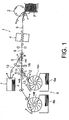
- Fig. 1 is a schematic structure diagram of a sheet-handling system to which an embodiment of the present invention is applied;
- Fig. 2 is a schematic side view of an embodiment of a sheet take-out apparatus according to the present invention;
- Fig. 3 is a schematic perspective view of the sheet take-out apparatus shown in Fig. 2;
- Fig. 4 is a schematic perspective view of a sheet-feeding member and a guide plate shown in Fig. 2;
- Fig. 5 is a schematic cross-sectional view of a reverse-rotation rotor shown in Fig. 2;
- Figs. 6-8 show schematic take-out operations of the sheet take-out apparatus shown in Fig. 2;
- Fig. 9 is a schematic side view of a sheet take-out apparatus according to another embodiment of the present invention; and
- Fig. 10 is a schematic perspective view of the sheet take-out apparatus shown in Fig. 9.
-
- Embodiments of the present invention will be explained below with reference to the attached drawings. It should be noted that the present invention is not limited to the embodiments but covers their equivalents. Throughout the attached drawings, similar or same reference numerals show similar, equivalent or same components. The drawings, however, are shown schematically for the purpose of explanation so that their components are not necessarily the same in shape or dimension as actual ones. In other words, concrete shapes or dimensions of the components should be considered as described in these specifications, not in view of the ones shown in the drawings. Further, some components shown in the drawings may be different in dimension or ratio from each other.
- A sheet take-out apparatus and a method of taking out sheets of the first embodiment of the present invention will be explained below with reference to the attached drawings.
- First, with reference to Fig. 1 an explanation will be provided for sheet-handling system 1 to which the present invention is applied. Sheet-handling system 1 successively takes out sheets from a bundle of stacked sheets and conveys them for further treatments, such as examination and classification of the sheets into usable and discard ones. By way of example, the sheet-handling rate of sheet-handling system 1 is tens of sheets per second while the conveying speed is several meters per second. The rate and speed are always constant.
- As shown in Fig. 1, sheet-handling system 1 is provided with sheet take-
out apparatus 2, conveyor 3,processing unit 4, separator 5, and the first andsecond stackers apparatus 2 successively takes out one sheet P at a time at a predetermined rate. Conveyor 3 coveys sheet P taken out by sheet take-outapparatus 2 in a predetermined direction.Processing unit 4 carries out a predetermined treatment for sheet P. In response to treatment information supplied fromprocessing unit 4 separator 5 sends sheet P to either the first orsecond stacker - As will be set forth later in detail, sheet take-out
apparatus 2 takes out one sheet P at a time from the upper portion of a bundle of "n" stacked sheets (n: an arbitrary integer). Sheet take-outapparatus 2 delivers the sheet P to conveyor 3, which conveys the same held by its conveying belts at a constant speed. -
Processing unit 4 is disposed to faceconveying path 9 in front of sheet take-out apparatus 2.Processing unit 4 examines the surface of sheet P taken out by sheet take-outapparatus 2 to check how much it is torn or how dirty it is. Consequently,processing unit 4 determines in light of results of such checking whether sheet P is still usable or must be discarded. - Separator 5 has the
first gate 14A that sends sheets in conveying direction A or B in response to processing information supplied fromprocessing unit 4 and thesecond gate 14B that sends sheets in conveying direction C or D in accordance with a predetermined number of conveyed sheets. - More particularly, the
first gate 14A guides the sheets selected to be discarded in response to the processing information to thesecond stacker 7 through the first conveying branch 10. Thefirst gate 14A also guides those determined to be still usable in response to the processing information to thefirst stacker 6 through the second conveying branch 11. - The
second gate 14B, on the other hand, conveys the predetermined number of the sheets to thefirst stacker unit 6a of thefirst stacker 6 through thethird conveying branch 12. Thesecond gate 14B also conveys the predetermined number of the sheets to thesecond stacker unit 6b of thefirst stacker 6 through thefourth conveying branch 13. - The
first stacker 6 has the first andsecond stacker units second stacker wheels Stacker wheels Stacker wheels second stacker units - Passing number of sheets P conveyed to the
first stacker 6 is counted byoptical sensor 18 provided opposite to the second conveying branch 11. Whenever the number of sheets P is counted to a predetermined one, e.g., 100, thesecond gate 14B is turned to alternatively stack 100 sheets at thefirst stacker unit 6a or thesecond stacker unit 6b. - The
second stacker 7 receives conveying sheets P to stack a bundle of sheets P again. The sheets stacked are then cut out by a shredder for discarding. - The structure of sheet take-
out apparatus 2 will be described with reference to Figs. 2-4. - Sheet take-
out apparatus 2 primarily consists ofsheet feeder 20,depression unit 27,air spout unit 26 and take-out unit 30. -
Sheet feeder 20 is provided with sheet-feeding member 22, movable sheet-feeding member 21 and upper surfaceposition detection lever 23. A bundle of sheets are stacked on sheet-feeding member 22. Movable sheet-feeding member 21 is used to move sheet-feeding member 22 in a direction (e.g., an up and down direction) in parallel with the stacking direction of sheets P. Upper surfaceposition detection lever 23 is a position sensor that detects the upper surface position (i.e., the top surface position) of the bundle of sheets stacked on sheet-feeding member 22. Upper surfaceposition detection lever 23 converts the upper surface position into an electric signal and sends it to a controller not shown in the drawings. The controller controls movable sheet-feedingmember 21 in response to the electric signal to move sheet-feedingmember 22 so that it sets the top surface of sheets P to a fixed position in the vicinity of take-outunit 30. -
Sheet feeder 20 is provided with frontedge guide plate 24 fixed at the front portion of sheet-feedingmember 22 on the front edge side along the longitudinal or taking-out direction of the stacked sheets. Frontedge guide plate 24 performs to line up the front edge of sheets P and to adjust the posture of sheet P by guiding its lower side when take-outunit 30 delivers sheet P to conveyor 3. -
Sheet feeder 20 is also equipped with rearedge guide plate 28 provided at the rear portion of sheet-feedingmember 22, i.e., the rear edge side along the longitudinal or taking-out direction of the stacked sheets. Rearedge guide plate 28, which is movable along the longitudinal or taking-out direction of sheets P placed on sheet-feedingmember 22 to adjust its own position depending on lengths of sheets P, controls a position of sheets P on the rear edge side. -
Sheet feeder 20 further includes both-side guide plates 29 provided at both sides of sheet-feedingmember 22 to guide the width of a bundle of sheets. Sheet-feedingmember 22 consists ofrod members 22A that are in parallel with each other and arranged to be on the same plane. Both-side guide plates 29 each are provided withslits 29S in whichrod members 22A are movably held, respectively. The width ofslit 29S is approximately the same as the diameter ofrod member 22A whileslit 29S is long in direction Y and rounded at both ends. - When
rod members 22A of sheet-feedingmember 22 are moved by movable sheet-feedingmember 21,rod members 22A move along slits 29S in direction Y, i.e., in the sheet-stacking direction. Both-side guide plates 29 are movable in accordance with the width of a bundle of sheets in direction X whilerod members 22A are kept engaged withslits 29S. -
Depression unit 27 depresses a bundle of sheets against sheet-feedingmember 22. Thus,depression unit 27 is provided withair nozzle 27A that spouts out air toward sheet-feedingmember 22.Air nozzle 27A is fixed to face sheet-feedingmember 22 so that it spouts out air to depresses the top one of stacked sheets P placed on the sheet-feedingmember 22. -
Air nozzle 27A is preferably disposed at a rear position from the center of a bundle of sheets stacked on sheet-feedingmember 22. In the case that the stacked sheets are 120 mm through 170 mm long and 60 mm through 90 mm wide, the position toward whichair nozzle 27A is directed is far by about 60 mm through about 85 mm or farther from the front edge of stacked sheets P and an air depression pressure against the sheet is set to 10 kPa through 15 kPa. -
Air spout unit 26 also spouts out air to the front end side in the taking-out direction of the stacked sheets depressed bydepression unit 27.Air spout unit 26 is provided with at least one of the first andsecond air nozzles unit 30. - In this embodiment, the first and
second air nozzles member 22, respectively. The first andsecond air nozzles side guide plates 29 and spout air at a pressure of 10 kPa through 15 kPa. - Thus, edge portions of the first and
second air nozzles side guide plates 29 move to line up both edges of the sheets. With this structure, therefore, a gap defined between the side edge of the sheets and the edge portion of the first andsecond air nozzles - Here, the vicinity of take-out
unit 30 with respect to positions of the first andsecond air nozzles member 22 than their center PC and that is in the vicinity where the top one of the sheets P contacts with take-outunit 30. - The first and
second air nozzles second air nozzles - As described above, since
depression unit 27 depresses the rear edge side of the sheet stacked on sheet-feedingmember 22 andair spout unit 26 spouts air to both sides of the sheets, the air remains at the front edge portion to keep the sheets P separate from each other. - Take-out
unit 30 takes out a sheet from the front edge portion of the sheets in the longitudinal or taking-out direction whileair spout unit 26 spouts air to the sheets. Take-outunit 30 is provided with take-outrotor 31 andreverse rotation rotor 32. Take-outrotor 31 rotates in the forward direction to take out a sheet on the top surface of the sheets as shown with an arrow in Fig. 2.Reverse rotation rotor 32 rotates in the direction to return excessive sheets taken out by take-outrotor 31 to sheet-feedingmember 22 as also shown with an arrow in Fig. 2.Reverse rotation rotor 32 is provided underneath take-outrotor 31 and closer to sheet-feedingmember 22 than to take-outrotor 31. - Take-out
rotor 31 andreverse rotation rotor 32 are driven independently by rotation drive devices, respectively. A angular velocity ratio of take-outrotor 31 to reverse rotation rotor is set to approximately 10:7, for instance. In this embodiment, take-outrotor 31 with a diameter of 80 mm rotates at a speed of 1,200 r.p.m. (rotations per minute) whilereverse rotation rotor 32 with a diameter of 40 mm rotates at a speed of 800 r.p.m. - Take-out
rotor 31 andreverse rotation rotor 32 are provided withsuction holes rotor 31 is set to be substantially the same in suction pressure, e.g., 35 kPa through 40 kPa, asreverse rotation rotor 32. - Since take-out
rotor 31 is also substantially the same in structure asreverse rotation rotor 32, the structure ofreverse rotation rotor 32 will be described below. As shown in Fig. 5,reverse rotation rotor 32 has cylinder-like rotor 32X andstator 32b in the inside of cylinder-like rotor 32X.Stator 32b is provided with cut-outportion 32c opposite to take-outrotor 31 to define a chamber. - With this structure, when cylinder-
like rotor 32X rotates,only suction holes 32a facing cut-outportion 32c suck air so that sheet P sucked bysuction holes 32a is conveyed back to sheet-feedingmember 22 in the predetermined direction. - A friction coefficient of the surface of take-out
rotor 31 is set to be larger than that ofreverse rotation rotor 32. The surface of take-outrotor 31 is made of a rather high friction coefficient material such as rubber while that ofreverse rotation rotor 32 is a metallic material such as stainless steel. - In take-out
unit 30, take-outrotor 31 rotates to take out the top one of sheets P placed on sheet-feedingmember 22. Thus, the sheet P in contact with the surface of take-outrotor 31 is taken out by the high friction. -
Reverse rotation rotor 32, on the other hand, rotates in the direction to avoid sending out sheet P.Reverse rotation rotor 32 sucks, and returns tosheet feeder 20, sheets P that are not sucked by take-outrotor 31. Thus, this prevents take-outrotor 31 from delivering excessive sheets to conveyor 3. Take-outrotor 31 can take out sheets P at a speed of 275 m/sec, for instance. - A method of taking out sheets will be explained below with reference to sheet take-out
apparatus 2 set forth above. - First, upper surface
position detection lever 23 detects the upper surface of a bundle of sheets placed on sheet-feedingmember 22. In response to detection results provided by upper surfaceposition detection lever 23, movable sheet-feedingmember 21 is controlled to lift up sheet-feedingmember 22 until the upper surface of the sheets reaches a proper position as shown in Fig. 6. - When the upper surface of the sheets reach to the proper position,
air nozzle 27A ofdepression unit 27 spouts air toward the sheets to depress the upper surface of the sheets in the direction against sheet-feedingmember 22. At the same time, the first andsecond air nozzles air spout unit 26 spout air toward both sides of the sheets. The air causes sheets P to separate from each other and to float. - As shown in Fig. 7, several sheets P positioned at the upper part of the bundle of sheets float on the front edge side close to take-out
unit 30 due to the air from the first andsecond air nozzles air nozzle 27A prevents the rear edge portion of the sheets from floating. Since the sheets are depressed at the rear edge portion, the air spouted to the front edge side stays there to make the sheets P separate effectively. - As shown in Fig. 8, when the sheets P are separated at the front edge of the sheets, the rotation drive devices rotate take-out
rotor 31 andreverse rotation rotor 32 in the predetermined directions.Suction holes 31a of take-outrotor 31 sucks and takes out the separated sheet P whilesuction holes 32a ofreverse rotation rotor 32 also sucks excessive sheets that are not sucked bysuction holes 31a and returns them back tosheet feeder 20. This prevents take-outrotor 31 from taking out a plurality of sheets at a time. -
Air spout unit 26 in the embodiment described above with reference to Fig. 2 is provided with a pair ofair nozzles air nozzle - As shown in Figs. 9 and 10, however, in addition to the first and
second air nozzles third air nozzle 26C may be further provided at a place that is lower (closer to sheet-feeding member 22) than those of the first andsecond air nozzles third air nozzle 26C from the same compressor for the first andsecond air nozzles -
Air spout unit 26 provided with the three air nozzles can handle even the lower part of the sheets P and keep them separate from each other at the front edge portion of sheets P. Thus, take-outunit 30 is capable of avoiding taking out excessive sheets effectively. - As described above, in the sheet take-out apparatus and method of taking out sheets according to the embodiments, while a bundle of the sheets placed on the sheet-feeding member are depressed against the sheet-feeding member, air is spouted to the sides of a bundle of sheets in the longitudinal or taking-out direction. Thus, the air can be kept at the necessary portion of the sheets.
- In other words, air is spouted from the upper position over the sheets to the rear edge portion of the sheets so that the rear edge of the sheets is depressed. Further, in this condition, air spouted to the front edge side of the sheets stay at the front edge side and keeps some sheets separate from each other at the front edge. Thus, irrespective of surface conditions of the sheets, the take-out of excessive sheets can be securely avoided.
- The present invention provides a sheet take-out apparatus and a method of taking out sheets which are capable of taking out one necessary sheet at a time regardless of surface conditions of the sheets.
- Although the invention has been described in its preferred form with a certain degree of particularity, it is understood that the present disclosure of the preferred form has been changed in the details of construction and the combination and arrangement of components may be resorted to without departing from the spirit and the scope of the invention as hereinafter claimed.
- It is explicitly stated that all features disclosed in the description and/or the claims are intended to be disclosed separately and independently from each other for the purpose of original disclosure as well as for the purpose of restricting the claimed invention independent of the compositions of the features in the embodiments and/or the claims. It is explicitly stated that all value ranges or indications of groups of entities disclose every possible intermediate value or intermediate entity for the purpose of original disclosure as well as for the purpose of restricting the claimed invention, in particular as limits of value ranges.
Claims (12)
- A sheet take-out apparatus comprising:a sheet-feeding member (22) on which sheets (P) are placed;an air spout unit (26) to spout out air toward a side of said sheets;a take-out unit (30) to take out a sheet from said sheets in a taking-out direction; anda depression member (27) to depress said sheets against said sheet-feeding member on a rear edge side located behind a central portion of said sheets with respect to the taking-out direction of said take-out unit.
- A sheet take-out apparatus according to Claim 1, wherein said air spout unit comprises an air nozzle (26A, B) provided in a vicinity of said take-out unit.
- A sheet take-out apparatus according to Claim 1 or 2 wherein said air spout unit comprises first and second air nozzles (26A, B) provided on both sides of the sheets placed on said sheet-feeding member.
- A sheet take-out apparatus according to Claim 3, wherein said air spout unit further comprises a third air nozzle (26C) provided on a rear edge side of the sheets that is farther from said take-out unit than a place of said first air nozzle.
- A sheet take-out apparatus according to one of claims 1 to 4, wherein said depression member comprises an air jet nozzle (27A) to depress said sheets against said sheet-feeding member on a rear edge side located behind a central portion of said sheets with respect to a taking-out direction of said take-out unit.
- A sheet take-out apparatus according to Claim 5, wherein a pointed end of said air jet nozzle (27A) is provided on a rear edge side that is farther from said take-out unit than the center of said sheets placed on said sheet-feeding member.
- A sheet take-out apparatus according to one of claims 1 to 6, wherein said take-out unit (30) comprises a take-out rotor (31) to take out a top sheet and a reverse rotation rotor (32) that rotates in reverse with respect to said take-out rotor and returns excessive sheets taken from said sheets to said sheet-feeding member.
- A sheet take-out apparatus according to Claim 7, wherein said take-out rotor and said reverse rotation rotor each are provided with surfaces in which suction holes are defined to suck a sheet from said sheets.
- A sheet take-out apparatus according to Claim 7 or 8, wherein a friction coefficient of said surface of said take-out rotor is larger than that of said surface of said reverse rotation rotor.
- A sheet take-out apparatus according to one of claims 1 to 9, further comprising guide members (29) provided on both sides of the sheet placed on said sheet-feeding member (22) to adjust a position of said sheets in a width direction thereof.
- A sheet take-out apparatus according to Claim 10, wherein said air spout unit is attached to said guide members.
- A method of taking out a sheet comprising:placing sheets (P) on a sheet-feeding member (22);spouting out air toward a side of said bundle of sheets;taking out a sheet from said bundle of sheets toward which the air is spouted; anddepressing said bundle of sheets against said sheet-feeding member on a rear edge side located behind a central potion of said depressed sheets with respect to a taking-out direction of said take-out unit.
Applications Claiming Priority (2)
| Application Number | Priority Date | Filing Date | Title |
|---|---|---|---|
| JP2003168123 | 2003-06-12 | ||
| JP2003168123A JP2005001838A (en) | 2003-06-12 | 2003-06-12 | Paper sheet take-out device and paper sheet take-out method |
Publications (2)
| Publication Number | Publication Date |
|---|---|
| EP1486440A1 true EP1486440A1 (en) | 2004-12-15 |
| EP1486440B1 EP1486440B1 (en) | 2008-10-29 |
Family
ID=33296880
Family Applications (1)
| Application Number | Title | Priority Date | Filing Date |
|---|---|---|---|
| EP04011191A Expired - Lifetime EP1486440B1 (en) | 2003-06-12 | 2004-05-11 | Sheet take-out apparatus and method of taking out sheets |
Country Status (6)
| Country | Link |
|---|---|
| US (1) | US7222846B2 (en) |
| EP (1) | EP1486440B1 (en) |
| JP (1) | JP2005001838A (en) |
| CN (1) | CN100355637C (en) |
| AT (1) | ATE412599T1 (en) |
| DE (1) | DE602004017382D1 (en) |
Families Citing this family (10)
| Publication number | Priority date | Publication date | Assignee | Title |
|---|---|---|---|---|
| JP4537919B2 (en) * | 2005-09-15 | 2010-09-08 | 株式会社東芝 | Tray device |
| JP4609264B2 (en) * | 2005-09-27 | 2011-01-12 | 富士ゼロックス株式会社 | Sheet feeding device |
| JP4881206B2 (en) * | 2006-05-11 | 2012-02-22 | 株式会社東芝 | Paper sheet separating and taking out device |
| JP2012188274A (en) * | 2011-03-11 | 2012-10-04 | Toshiba Corp | Paper sheet take-out device |
| US8317185B1 (en) * | 2011-05-05 | 2012-11-27 | Xerox Corporation | Method and apparatus for feeding media sheets in an image production device |
| CN103280018B (en) * | 2013-03-04 | 2016-03-30 | 上海古鳌电子科技股份有限公司 | A kind of impeller driving device of paper currency sorter |
| CN103955992B (en) * | 2014-04-24 | 2017-12-08 | 中国人民银行印制科学技术研究所 | A kind of method and apparatus for separating sheet article |
| KR101827062B1 (en) * | 2015-12-07 | 2018-02-07 | 현대자동차주식회사 | Feul Cell Static Material Supply Apparatus and Supply Method |
| JP6790363B2 (en) * | 2016-01-25 | 2020-11-25 | 株式会社リコー | Supply device, image formation system, object inspection system |
| CN106241439B (en) * | 2016-09-29 | 2018-01-02 | 河南省新斗彩印刷有限公司 | Semi-automatic die cutting machine automatic document feeder |
Citations (3)
| Publication number | Priority date | Publication date | Assignee | Title |
|---|---|---|---|---|
| US4324394A (en) * | 1977-07-01 | 1982-04-13 | G A O Gesellschaft fur Automation and Organisation mbH | Device for separating record carrying items |
| GB2207422A (en) * | 1987-06-10 | 1989-02-01 | Corah Plc | Air jet separation device |
| US20010017441A1 (en) * | 2000-02-23 | 2001-08-30 | Kyocera Mita Corporation | Paper feeder for use in image forming apparatus |
Family Cites Families (31)
| Publication number | Priority date | Publication date | Assignee | Title |
|---|---|---|---|---|
| US8796A (en) * | 1852-03-16 | Double-plane iron | ||
| US2812178A (en) * | 1953-05-11 | 1957-11-05 | Dux Ab | Sheet feeding apparatus |
| GB1228575A (en) * | 1967-08-16 | 1971-04-15 | ||
| US3504910A (en) * | 1968-06-06 | 1970-04-07 | Us Army | Fluidic singulator |
| US3726454A (en) * | 1971-12-21 | 1973-04-10 | D Robbins | Envelope opening machine |
| IT1033549B (en) * | 1973-06-14 | 1979-08-10 | Herold Maschf Hans | DEVICE FOR THE EXACT SQUARING OF PAPER STACKS, THICK PAPER AND CARDBOARD |
| US3861668A (en) * | 1973-10-23 | 1975-01-21 | Vernon Wood | Sheet registration apparatus for printing machine |
| GB1561264A (en) * | 1976-10-05 | 1980-02-20 | Htb Ltd | Sheet feeding machines |
| DD141150B1 (en) * | 1979-02-14 | 1981-10-28 | Hans Zimmermann | BULBING DEVICE IN BENDERS OF ARC-MACHINING MACHINES |
| CA1140601A (en) * | 1979-03-30 | 1983-02-01 | Emile F. Stievenart | Method and device for separating a sheet from a stack of sheets |
| US4395035A (en) * | 1980-12-24 | 1983-07-26 | International Business Machines Corporation | Air shingler |
| DE3447777A1 (en) * | 1984-12-28 | 1986-07-10 | GAO Gesellschaft für Automation und Organisation mbH, 8000 München | DEVICE AND METHOD FOR SEPARATING LEAF |
| JPS62140948A (en) * | 1985-12-12 | 1987-06-24 | Seiko Epson Corp | How to separate IC pallets |
| DE3706058A1 (en) * | 1987-02-25 | 1988-09-08 | Heidelberger Druckmasch Ag | FEEDER FOR A PRINTING MACHINE |
| JPH0192138A (en) * | 1987-09-30 | 1989-04-11 | Toshiba Corp | Paper feed device |
| JPH0213530A (en) * | 1988-06-30 | 1990-01-17 | Toshiba Corp | Paper feed device |
| US4978416A (en) * | 1988-10-28 | 1990-12-18 | B & H Manufacturing Company, Inc. | Stack fed labeling machine |
| GB2233964B (en) * | 1989-07-04 | 1994-03-23 | Isamu Miura | Paper arranging system |
| US5135213A (en) * | 1990-10-15 | 1992-08-04 | Xerox Corporation | Apparatus for method for high speed sheet feeding |
| US5704607A (en) * | 1994-09-28 | 1998-01-06 | De La Rue Systems Limited | Sheet feed and presenting assembly |
| JPH08151135A (en) | 1994-09-30 | 1996-06-11 | Toshiba Corp | Paper take-out device |
| JP3529916B2 (en) | 1995-10-23 | 2004-05-24 | 株式会社東芝 | Paper sheet unloading device and unloading operation stopping method |
| JPH10101239A (en) | 1996-09-30 | 1998-04-21 | Toshiba Corp | Paper processing equipment |
| JP3579207B2 (en) | 1997-03-10 | 2004-10-20 | 株式会社東芝 | Operating method of paper processing equipment |
| JP2000185829A (en) * | 1998-12-23 | 2000-07-04 | Xerox Corp | Paper feeder |
| US6629692B2 (en) * | 2000-02-25 | 2003-10-07 | Nexpress Solutions Llc | Device for separating an uppermost sheet from a supply stack by means of air blowers |
| US6264188B1 (en) * | 2000-06-12 | 2001-07-24 | Xerox Corporation | Sheet feeding apparatus having an adaptive air fluffer |
| EP1326796B1 (en) * | 2000-10-10 | 2005-02-02 | GRONBJERG, Ib | A stacker for die-cut products |
| US6345921B1 (en) * | 2000-12-08 | 2002-02-12 | Hewlett-Packard Company | Sheet feeding apparatus employing air streams as handling media |
| US6669187B1 (en) * | 2002-06-13 | 2003-12-30 | Xerox Corporation | Rear jet air knife |
| US6863272B2 (en) * | 2002-08-29 | 2005-03-08 | Xerox Corporation | Sheet feeding apparatus having an adaptive air fluffer |
-
2003
- 2003-06-12 JP JP2003168123A patent/JP2005001838A/en active Pending
-
2004
- 2004-03-31 US US10/813,114 patent/US7222846B2/en not_active Expired - Fee Related
- 2004-05-11 AT AT04011191T patent/ATE412599T1/en not_active IP Right Cessation
- 2004-05-11 DE DE602004017382T patent/DE602004017382D1/en not_active Expired - Fee Related
- 2004-05-11 EP EP04011191A patent/EP1486440B1/en not_active Expired - Lifetime
- 2004-05-27 CN CNB2004100475825A patent/CN100355637C/en not_active Expired - Fee Related
Patent Citations (3)
| Publication number | Priority date | Publication date | Assignee | Title |
|---|---|---|---|---|
| US4324394A (en) * | 1977-07-01 | 1982-04-13 | G A O Gesellschaft fur Automation and Organisation mbH | Device for separating record carrying items |
| GB2207422A (en) * | 1987-06-10 | 1989-02-01 | Corah Plc | Air jet separation device |
| US20010017441A1 (en) * | 2000-02-23 | 2001-08-30 | Kyocera Mita Corporation | Paper feeder for use in image forming apparatus |
Also Published As
| Publication number | Publication date |
|---|---|
| DE602004017382D1 (en) | 2008-12-11 |
| EP1486440B1 (en) | 2008-10-29 |
| US7222846B2 (en) | 2007-05-29 |
| ATE412599T1 (en) | 2008-11-15 |
| JP2005001838A (en) | 2005-01-06 |
| CN1572686A (en) | 2005-02-02 |
| US20040251591A1 (en) | 2004-12-16 |
| CN100355637C (en) | 2007-12-19 |
Similar Documents
| Publication | Publication Date | Title |
|---|---|---|
| EP2960191B1 (en) | Suctioning and conveying system | |
| EP0528493B1 (en) | Roller-accumulator for sheets | |
| US4887805A (en) | Top vacuum corrugation feeder | |
| EP1486440B1 (en) | Sheet take-out apparatus and method of taking out sheets | |
| US10494207B2 (en) | Sheet feeding device and image forming system | |
| WO2007149973A2 (en) | Method and apparatus for jogging and feeding sortable articles | |
| JPH0867368A (en) | Paper feeder | |
| JP6242996B2 (en) | Paper sheet processing equipment | |
| US7467703B2 (en) | Device for separating overlapping flat products | |
| US20020140162A1 (en) | Stacker | |
| JPH06107347A (en) | Paper feeder | |
| JP2011190022A (en) | Paper feeder | |
| US20170253446A1 (en) | Sheet takeout and separation device and sheet processing apparatus | |
| CN100340460C (en) | Means for aligning paper stacked in a stack and means for feeding paper | |
| JP3620198B2 (en) | Paper sheet separator | |
| JP3710255B2 (en) | Air separation paper feeder | |
| JP2831453B2 (en) | Paper feeder | |
| JPH034463B2 (en) | ||
| JP4624185B2 (en) | Paper sheet processing equipment | |
| JP4766684B2 (en) | Paper transport device | |
| JP2000053305A (en) | Stacker equipment | |
| JP2019119565A (en) | Paper feeder and double feeding prevention method of paper sheet body | |
| EP2987753B1 (en) | Sheet takeout device and sheet processing apparatus | |
| JP4549238B2 (en) | Paper feeder | |
| JPH0820451A (en) | Document Separation Feeder |
Legal Events
| Date | Code | Title | Description |
|---|---|---|---|
| PUAI | Public reference made under article 153(3) epc to a published international application that has entered the european phase |
Free format text: ORIGINAL CODE: 0009012 |
|
| 17P | Request for examination filed |
Effective date: 20040511 |
|
| AK | Designated contracting states |
Kind code of ref document: A1 Designated state(s): AT BE BG CH CY CZ DE DK EE ES FI FR GB GR HU IE IT LI LU MC NL PL PT RO SE SI SK TR |
|
| AX | Request for extension of the european patent |
Extension state: AL HR LT LV MK |
|
| AKX | Designation fees paid |
Designated state(s): AT DE FR IT TR |
|
| 17Q | First examination report despatched |
Effective date: 20060717 |
|
| GRAP | Despatch of communication of intention to grant a patent |
Free format text: ORIGINAL CODE: EPIDOSNIGR1 |
|
| GRAS | Grant fee paid |
Free format text: ORIGINAL CODE: EPIDOSNIGR3 |
|
| GRAA | (expected) grant |
Free format text: ORIGINAL CODE: 0009210 |
|
| AK | Designated contracting states |
Kind code of ref document: B1 Designated state(s): AT DE FR IT TR |
|
| REF | Corresponds to: |
Ref document number: 602004017382 Country of ref document: DE Date of ref document: 20081211 Kind code of ref document: P |
|
| PG25 | Lapsed in a contracting state [announced via postgrant information from national office to epo] |
Ref country code: IT Free format text: LAPSE BECAUSE OF FAILURE TO SUBMIT A TRANSLATION OF THE DESCRIPTION OR TO PAY THE FEE WITHIN THE PRESCRIBED TIME-LIMIT Effective date: 20081029 |
|
| PLBE | No opposition filed within time limit |
Free format text: ORIGINAL CODE: 0009261 |
|
| STAA | Information on the status of an ep patent application or granted ep patent |
Free format text: STATUS: NO OPPOSITION FILED WITHIN TIME LIMIT |
|
| 26N | No opposition filed |
Effective date: 20090730 |
|
| REG | Reference to a national code |
Ref country code: FR Ref legal event code: ST Effective date: 20100129 |
|
| PG25 | Lapsed in a contracting state [announced via postgrant information from national office to epo] |
Ref country code: FR Free format text: LAPSE BECAUSE OF NON-PAYMENT OF DUE FEES Effective date: 20090602 |
|
| PG25 | Lapsed in a contracting state [announced via postgrant information from national office to epo] |
Ref country code: DE Free format text: LAPSE BECAUSE OF NON-PAYMENT OF DUE FEES Effective date: 20091201 |
|
| PG25 | Lapsed in a contracting state [announced via postgrant information from national office to epo] |
Ref country code: AT Free format text: LAPSE BECAUSE OF NON-PAYMENT OF DUE FEES Effective date: 20090511 |
|
| PG25 | Lapsed in a contracting state [announced via postgrant information from national office to epo] |
Ref country code: TR Free format text: LAPSE BECAUSE OF FAILURE TO SUBMIT A TRANSLATION OF THE DESCRIPTION OR TO PAY THE FEE WITHIN THE PRESCRIBED TIME-LIMIT Effective date: 20081029 |