EP1486328A2 - Intaglio printing machine with a screen cylinder - Google Patents
Intaglio printing machine with a screen cylinder Download PDFInfo
- Publication number
- EP1486328A2 EP1486328A2 EP04101711A EP04101711A EP1486328A2 EP 1486328 A2 EP1486328 A2 EP 1486328A2 EP 04101711 A EP04101711 A EP 04101711A EP 04101711 A EP04101711 A EP 04101711A EP 1486328 A2 EP1486328 A2 EP 1486328A2
- Authority
- EP
- European Patent Office
- Prior art keywords
- cylinder
- printing
- screen printing
- screen
- ink
- Prior art date
- Legal status (The legal status is an assumption and is not a legal conclusion. Google has not performed a legal analysis and makes no representation as to the accuracy of the status listed.)
- Withdrawn
Links
Images

Classifications
-
- B—PERFORMING OPERATIONS; TRANSPORTING
- B41—PRINTING; LINING MACHINES; TYPEWRITERS; STAMPS
- B41F—PRINTING MACHINES OR PRESSES
- B41F15/00—Screen printers
- B41F15/08—Machines
- B41F15/0804—Machines for printing sheets
- B41F15/0809—Machines for printing sheets with cylindrical or belt-like screens
-
- B—PERFORMING OPERATIONS; TRANSPORTING
- B41—PRINTING; LINING MACHINES; TYPEWRITERS; STAMPS
- B41F—PRINTING MACHINES OR PRESSES
- B41F11/00—Rotary presses or machines having forme cylinders carrying a plurality of printing surfaces, or for performing letterpress, lithographic, or intaglio processes selectively or in combination
- B41F11/02—Rotary presses or machines having forme cylinders carrying a plurality of printing surfaces, or for performing letterpress, lithographic, or intaglio processes selectively or in combination for securities
-
- B—PERFORMING OPERATIONS; TRANSPORTING
- B41—PRINTING; LINING MACHINES; TYPEWRITERS; STAMPS
- B41F—PRINTING MACHINES OR PRESSES
- B41F15/00—Screen printers
- B41F15/14—Details
- B41F15/34—Screens, Frames; Holders therefor
- B41F15/38—Screens, Frames; Holders therefor curved
-
- B—PERFORMING OPERATIONS; TRANSPORTING
- B41—PRINTING; LINING MACHINES; TYPEWRITERS; STAMPS
- B41F—PRINTING MACHINES OR PRESSES
- B41F9/00—Rotary intaglio printing presses
- B41F9/02—Rotary intaglio printing presses for multicolour printing
- B41F9/021—Sheet printing presses
Definitions
- the invention relates to an intaglio printing machine according to the preamble of Claim 1.
- EP 03 43 106 A2 describes a printing press with one on a forme cylinder arranged intaglio printing plate and a printing cylinder in which the Intaglio printing plate at the same time as wet offset printing plate for an additional Offset printing unit can serve.
- a printing press with an intaglio printing unit with forme cylinder and impression cylinder is also known from EP 03 51 366 B1.
- the gravure printing unit is in this printing press combined with an indirectly working printing unit, from which printed sheets with With the help of an intermediate sheet transport device.
- Printing machines of this type allow printing on top of one another with different ones Techniques on the same substrate with a high degree of registration. she are therefore preferred for printing documents that have a high degree must be secure against counterfeiting, such as banknotes, securities, ID documents etc.
- EP 08 64 421 A1 describes a printing press with exchangeable ones Ink application devices for different printing processes.
- EP 05 63 007 A1 shows an intaglio printing machine on its plate cylinder in addition to the stencil cylinder attached to the cylinder Stencil cylinder is employed.
- GB 511 049 A describes a printing press in which an engraved Plate cylinders are assigned to screen printing cylinders.
- the invention has for its object to provide an intaglio printing machine.
- the advantages that can be achieved with the invention are, in particular, that they are Print tactile features easily and with high registration accuracy in relation to other print motifs.
- the attachment of such tactile motifs is particularly desirable for banknotes, in order to include a visually impaired person enable safe detection of banknotes and differentiation of their denominations.
- the pressure plate of the forme cylinder of such a machine advantageously has Wells, which are not just wells for receiving one Ink can act, but also screen printing ink targeted in such depressions can be introduced to them subsequently with one of the shape of the recess to print the corresponding profile.
- the gravure printing process carried out with the printing press is preferably a batch printing process, i. H. there is a collecting cylinder on which different inks to be printed independently of each other, preferably with the help of template cylinders, and so created complete gravure motif in a single slit passage on the Substrate is transferred.
- the screen printing cylinder is on the forme cylinder arranged. In terms of the direction of production, it can be behind one for the Gravure printing device known per se can be arranged so that the Screen printing process takes place essentially unaffected by gravure printing.
- screen printing cylinders can also be attached to the form cylinder before such Wiping device can be arranged so that the screen printing ink in a corresponding manner how to wipe the ink.
- the screen printing cylinder is on the collecting cylinder arranged and applied the screen printing ink to this first.
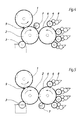
- the design of the printing press shown in schematic section in FIG. 1 has a plurality of inking units 8, each with a stencil cylinder 4 interact and color on raised areas of the assigned Transfer template cylinder 4.
- the template cylinders 4 in turn act with one Collection cylinder 6 together, on which they receive the ink received by the inking units 8 transfer. In this way, a multicolored pattern is formed on the collecting cylinder 6 generated, the colored zones of each of the raised areas of the template cylinder 4 correspond.
- the collecting cylinder 6 in turn acts with a forme cylinder 2, e.g. B. one Plate cylinder 2 together, on the gravure plates, in particular Steel line printing plates are mounted. These pressure plates are in contact with the Collection cylinder 6 colored according to the color pattern formed on the latter, the ink passing through the gap between plate cylinder 2 and Collecting cylinder 6 is essentially pressed into etched or engraved fine channels, that correspond to a detailed pattern to be printed on the substrate.
- a forme cylinder 2 e.g. B. one Plate cylinder 2 together
- the gravure plates in particular Steel line printing plates are mounted.
- These pressure plates are in contact with the Collection cylinder 6 colored according to the color pattern formed on the latter, the ink passing through the gap between plate cylinder 2 and Collecting cylinder 6 is essentially pressed into etched or engraved fine channels, that correspond to a detailed pattern to be printed on the substrate.
- the Wiper device 3 behind the gap is one Wiper device 3 arranged, those portions of the ink that are in the fine channels have
- the printing machine thus generates a complete intermediate image on the plate cylinder 2, that contains all the colors of the image to be printed and in one Gap passage is transferred to the substrate.
- This arrangement allows the Screen printing pattern with an extremely high degree of accuracy in relation to that Position rotogravure patterns on the printing plates and so one degree To achieve registration in two steps by promoting the Printing processes separate printing is not feasible.
- one expediently becomes a screen printing ink with a high viscosity compared to that lying on the surface of the impression cylinder 1 Choose gravure ink to avoid being on the flat surfaces of the printing plates applied screen printing ink when passing through the gap 9 to an undesirable extent is flattened, which could lead to an unclean print image and the tactility of the screen print pattern on the finished printed product.
- FIG. 2 differs from that of FIG. 1 by the arrangement of the screen printing cylinder 7 in the production direction behind the collecting cylinder 6 and in front of the Wiper device 3.
- FIG. 3 shows a section of a pressure plate for use in this press. Their surface ranges between plan, not printing Areas 13 each have fine channels 11 and larger depressions 12. The channels 11 can cross the depressions 12. The channels 11 each serve to receive printing ink from the collecting cylinder 6, whereas the larger recesses 12 for receiving Screen printing ink are provided.
- the wiper device 3 When passing through with printing and screen printing ink Colored plate cylinder 2 by the wiper device 3, the flat areas 13 of the printing plate freed of color, whereas in the channels 11 or depressions 12 the applied color remains and when passing through the gap 9 on the Substrate is transferred.
- the screen printing cylinder 7 is in the production direction arranged in front of the collecting cylinder 6. This has happened when using a pressure plate As shown in FIG. 3, the consequence is that the depressions 12 have already been filled with screen printing ink when inking takes place. As a result, when applying the Screen printing ink on the printing plate in the recesses 12 no printing ink is a color alienation of the screen printing ink by printing ink on finished printed product largely excluded.
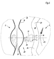
- Fig. 5 shows a further embodiment of the printing press, which is different from the above described differs in that the screen printing cylinder 7 on the collecting cylinder 6 is arranged instead of on the plate cylinder 2. It can there, as shown in the figure, based on the direction of production in front of the template cylinder 4, or behind them be arranged. In this embodiment, too, the plate cylinder 2 passes through applied screen printing ink the wiper device 3, the effects and advantages of this Design therefore essentially correspond to those with regard to the Embodiments of FIGS. 2 and 4 have been described.
- Fig. 6 shows in a partial section a structure of the screen printing cylinder 7, which in particular 1, 2 and 4, it is advantageous if the plate cylinder 2 Has circumferential areas that deviate from the exact cylinder shape, for. B. due from there arranged sheet grippers 21.
- Fig. 6 shows the vicinity of the gap that the Screen printing cylinder 7 forms with the plate cylinder 2.
- the screen printing cylinder 7 has in each case at its axial ends a support ring 14, on the outer circumference of a sieve 16, e.g. B. is spanned from silk or polyamide gauze or bronze wire mesh.
- a doctor blade 17 in the Inside the screen printing cylinder 7 is a doctor blade 17, the position of which is in the radial direction Direction, d. H. in the horizontal direction in the figure, through a curved body, here one on the end faces of the screen printing cylinder 7 formed guide slot 18 controlled through which a cylindrical guide extension 19 of the doctor blade 17 extends.
- the guide extension 19 is on both sides in the direction the axes of rotation of the two cylinders 2; 7 connecting line 20 slidably mounted.
- the Figure shows the doctor blade 17 in a position in which the sheet gripper 21 of the plate cylinder 2 the gap between the two cylinders 2; 7 passes through.
- the screen 16 has a radially inwardly indented peripheral section 22.
- the Guide slot 18 has a not shown in the figure, for cylindrical outer surface of the sieve 16 concentric circular arc-shaped section 23 and an inwardly indented section 24, the course of which Corresponds to circumferential section 22.
- section 24 is selected such that if the section 24 during the rotation of the screen printing cylinder 7 on the guide extension 19 moved past, the squeegee 17 is pulled back so far that it only exerts a minimal pressure on the screen 16 which does not result in any noteworthy Deformations of the screen 16 in the peripheral portion 22 results, or that they are in contact with completely loses the screen 16 and therefore no pressure on the peripheral portion 22 thereof exercises, which could deform it and damage it during operation.
- the guide extension 19 passes through in section 23 of the guide slot 18, presses the doctor blade 17 against the inside of the screen 16 in such a way that one on the doctor blade 17 Color 26 is pressed through the open areas of the screen 16 and on is applied to the plate cylinder 2 in this way.
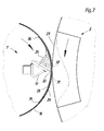
- the embodiment of the screen printing cylinder 7 shown in FIG. 7 is suitable if the Plate cylinder 2 no areas projecting over the radius of the printing plates, but at most has a concave section such as a channel 27.
- the Screen printing cylinder 7 is cylindrical over its entire circumference without one indented section.
- a doctor blade 17 is arranged, which is a pasty Paint 26 passes through the screen 16 stretched on the screen printing cylinder 7 and thereby exerts pressure radially outward on the screen 16.
- a support element 28 is arranged radially inside the sieve 16, which is located in Circumferential direction of the screen printing cylinder 7 over a peripheral portion 29 of the screen 16 extends, which corresponds to the expansion of the channel 27 on the plate cylinder 2.
- the Support element 28 is a closed plate which is curved in the form of a cylinder segment made of metal or strong plastic.
- the support element 28 is mounted radially inside the sieve 16, and leading End 31 and trailing end 32 of screen 16 overlap each other in that Support element 28 supported peripheral portion 29. In this way, the sensitive Connection between the two ends 31; 32 before contact with the squeegee 17 and thus protected against premature wear.
- the doctor blade 17 is guided with a Guide bodies such as the guide slot 18 from FIG. 6 are not required. Instead, the doctor blade 17 can move radially slightly against the force of a spring be displaceable or have a lip 33, the deformation of which is slight Radius fluctuations can compensate.
- the support element 28 is provided with a leading edge 34 and a trailing edge 36 which are chamfered in the circumferential direction of the screen printing cylinder 7 and not exactly parallel to a generating the outer surface of the screen printing cylinder 7 or to the lip 33 of the doctor blade 17, but at a small angle to it.
Abstract
Description
Die Erfindung betrifft eine Intaglio-Druckmaschine entsprechend dem Oberbegriff des Anspruches 1.The invention relates to an intaglio printing machine according to the preamble of Claim 1.
Aus EP 03 43 106 A2 ist eine Druckmaschine mit einer auf einem Formzylinder angeordneten Stichtiefdruckplatte und einem Druckzylinder bekannt, bei der die Stichtiefdruckplatte gleichzeitig als Nassoffsetdruckplatte für ein zusätzliches Offsetdruckwerk dienen kann.EP 03 43 106 A2 describes a printing press with one on a forme cylinder arranged intaglio printing plate and a printing cylinder in which the Intaglio printing plate at the same time as wet offset printing plate for an additional Offset printing unit can serve.
Eine Druckmaschine mit einem Tiefdruckwerk mit Formzylinder und Druckzylinder ist ferner aus der EP 03 51 366 B1 bekannt. Das Tiefdruckwerk ist in dieser Druckmaschine mit einem indirekt arbeitenden Druckwerk kombiniert, aus dem ihm bedruckte Bögen mit Hilfe einer zwischengeschalteten Bogentransportvorrichtung zugeführt werden.A printing press with an intaglio printing unit with forme cylinder and impression cylinder is also known from EP 03 51 366 B1. The gravure printing unit is in this printing press combined with an indirectly working printing unit, from which printed sheets with With the help of an intermediate sheet transport device.
Derartige Druckmaschinen erlauben das Übereinanderdrucken mit unterschiedlichen Techniken auf dem gleichen Bedruckstoff mit einem hohen Grad von Passerhaltigkeit. Sie werden daher bevorzugt für den Druck von Dokumenten eingesetzt, die einen hohen Grad an Fälschungssicherheit aufweisen müssen, wie etwa Banknoten, Wertpapiere, Ausweisdokumente etc.Printing machines of this type allow printing on top of one another with different ones Techniques on the same substrate with a high degree of registration. she are therefore preferred for printing documents that have a high degree must be secure against counterfeiting, such as banknotes, securities, ID documents etc.
Die EP 08 64 421 A1 beschreibt eine Druckmaschine mit austauschbaren Farbauftrageinrichtungen für unterschiedliche Druckverfahren.EP 08 64 421 A1 describes a printing press with exchangeable ones Ink application devices for different printing processes.
Die EP 05 63 007 A1 zeigt eine Intaglio-Druckmaschine, an deren Plattenzylinder zusätzlich zu dem am Zylinder angestellten Schablonenzylinder ein weiterer Schablonenzylinder angestellt ist. EP 05 63 007 A1 shows an intaglio printing machine on its plate cylinder in addition to the stencil cylinder attached to the cylinder Stencil cylinder is employed.
Die DE 197 46 268 A1 offenbart, Lacke unterschiedlicher Viskosität mittels unterschiedlicher Druckverfahren aufzubringen.DE 197 46 268 A1 discloses paints of different viscosities different printing processes.
Die GB 511 049 A beschreibt eine Druckmaschine, bei der einem gravierten Plattenzylinder Siebdruckzylinder zugeordnet sind.GB 511 049 A describes a printing press in which an engraved Plate cylinders are assigned to screen printing cylinders.
Der Erfindung liegt die Aufgabe zugrunde, eine Intaglio-Druckmaschine zu schaffen.The invention has for its object to provide an intaglio printing machine.
Die Aufgabe wird erfindungsgemäß durch die Merkmale des Anspruches 1 gelöst.The object is achieved by the features of claim 1.
Die mit der Erfindung erzielbaren Vorteile bestehen insbesondere darin, dass sie das Drucken von tastbaren Merkmalen auf einfache Weise und mit hoher Passergenauigkeit in Bezug auf weitere Druckmotive ermöglicht. Die Anbringung derartiger tastbarer Motive ist insbesondere bei Geldscheinen erwünscht, um auch sehbehinderten Personen eine sichere Erkennung der Banknoten und Unterscheidung ihrer Nennwerte zu ermöglichen.The advantages that can be achieved with the invention are, in particular, that they are Print tactile features easily and with high registration accuracy in relation to other print motifs. The attachment of such tactile motifs is particularly desirable for banknotes, in order to include a visually impaired person enable safe detection of banknotes and differentiation of their denominations.
Die Druckplatte des Formzylinders einer solchen Maschine weist vorteilhafterweise Vertiefungen auf, wobei es sich dabei nicht nur um Vertiefungen zum Aufnehmen einer Druckfarbe handeln kann, sondern auch Siebdruckfarbe gezielt in derartige Vertiefungen eingebracht werden kann, um sie anschließend mit einem der Form der Vertiefung entsprechenden Profil zu drucken.The pressure plate of the forme cylinder of such a machine advantageously has Wells, which are not just wells for receiving one Ink can act, but also screen printing ink targeted in such depressions can be introduced to them subsequently with one of the shape of the recess to print the corresponding profile.
Bei dem mit der Druckmaschine ausgeführten Tiefdruckverfahren handelt es sich vorzugsweise um ein Sammeldruckverfahren, d. h. es existiert ein Sammelzylinder, auf dem verschiedene zu druckende Druckfarben jeweils unabhängig voneinander, vorzugsweise mit Hilfe von Schablonenzylindern, aufgetragen werden und das so erzeugte vollständige Tiefdruckmotiv in einem einzigen Spaltdurchgang auf den Bedruckstoff übertragen wird. The gravure printing process carried out with the printing press is preferably a batch printing process, i. H. there is a collecting cylinder on which different inks to be printed independently of each other, preferably with the help of template cylinders, and so created complete gravure motif in a single slit passage on the Substrate is transferred.
Einer ersten Ausgestaltung zufolge ist der Siebdruckzylinder an dem Formzylinder angeordnet. Er kann dort bezogen auf die Produktionsrichtung hinter einer für den Tiefdruck an sich bekannten Wischeinrichtung angeordnet sein, so dass der Siebdruckvorgang im wesentlichen unbeeinflusst durch den Tiefdruck abläuft. Der Siebdruckzylinder kann jedoch an dem Formzylinder auch vor einer solchen Wischeinrichtung angeordnet sein, so dass die Siebdruckfarbe in entsprechender Weise wie die Druckfarbe gewischt wird.According to a first embodiment, the screen printing cylinder is on the forme cylinder arranged. In terms of the direction of production, it can be behind one for the Gravure printing device known per se can be arranged so that the Screen printing process takes place essentially unaffected by gravure printing. The However, screen printing cylinders can also be attached to the form cylinder before such Wiping device can be arranged so that the screen printing ink in a corresponding manner how to wipe the ink.
Einer zweiten Ausgestaltung zufolge ist der Siebdruckzylinder an dem Sammelzylinder angeordnet und trägt die Siebdruckfarbe zunächst auf diesen auf.According to a second embodiment, the screen printing cylinder is on the collecting cylinder arranged and applied the screen printing ink to this first.
Ausführungsbeispiele der Erfindung sind in den Zeichnungen dargestellt und werden im folgenden näher beschrieben.Embodiments of the invention are shown in the drawings and are in following described in more detail.
Es zeigen:
- Fig. 1
- einen schematischen Schnitt durch eine erste Ausgestaltung der Druckmaschine;
- Fig. 2
- einen entsprechenden Schnitt durch eine zweite Ausgestaltung;
- Fig. 3
- die Oberfläche einer in der Druckmaschine verwendeten Tiefdruckplatte im Schnitt;
- Fig. 4 und Fig. 5
- einen Schnitt durch eine dritte bzw. vierte Ausgestaltung der Druckmaschine;
- Fig. 6 und Fig. 7
- jeweils einen Teilschnitt durch einen Siebdruckzylinder.
- Fig. 1
- a schematic section through a first embodiment of the printing press;
- Fig. 2
- a corresponding section through a second embodiment;
- Fig. 3
- the surface of a gravure plate used in the printing machine in section;
- 4 and 5
- a section through a third or fourth embodiment of the printing press;
- 6 and 7
- each a partial section through a screen printing cylinder.
Die in Fig. 1 im schematischen Schnitt dargestellte Ausgestaltung der Druckmaschine
weist eine Mehrzahl von Farbwerken 8 auf, die jeweils mit einem Schablonenzylinder 4
zusammenwirken und Farbe auf erhabene Bereiche des zugeordneten
Schablonenzylinders 4 übertragen. Die Schablonenzylinder 4 wirken ihrerseits mit einem
Sammelzylinder 6 zusammen, auf den sie die von den Farbwerken 8 empfangene Farbe
übertragen. Auf dem Sammelzylinder 6 wird auf diese Weise ein mehrfarbiges Muster
erzeugt, dessen farbige Zonen jeweils den erhabenen Bereichen der Schablonenzylinder
4 entsprechen.The design of the printing press shown in schematic section in FIG. 1
has a plurality of inking
Der Sammelzylinder 6 wirkt seinerseits mit einem Formzylinder 2, z. B. einem
Plattenzylinder 2 zusammen, auf dem Tiefdruckplatten, insbesondere
Stahlstrichdruckplatten, montiert sind. Diese Druckplatten werden im Kontakt mit dem
Sammelzylinder 6 entsprechend dem auf letzterem gebildeten Farbmuster eingefärbt,
wobei die Druckfarbe beim Durchgang durch den Spalt zwischen Plattenzylinder 2 und
Sammelzylinder 6 im wesentlichen in geätzte oder gravierte feine Kanäle gedrückt wird,
die einem auf dem Bedruckstoff zu druckenden, detailreichen Muster entsprechen. In
Produktionsrichtung, d. h. im Uhrzeigersinn in der Fig. 1, hinter dem Spalt ist eine
Wischeinrichtung 3 angeordnet, die jene Anteile der Druckfarbe, die in den feinen Kanälen
keinen Platz gefunden haben, von der Oberfläche des Plattenzylinders 2 beseitigt.The collecting
Im Anschluss an die Wischeinrichtung 3 ist an dem Umfang des Plattenzylinders 2 ein
Siebdruckzylinder 7 einer Siebdruckeinheit angeordnet. Dieser trägt eine Siebdruckfarbe
auf die mit der Druckfarbe voreingefärbten und gewischten Druckplatten des
Plattenzylinders 2 auf.Following the
In einem sich in Produktionsrichtung anschließenden Spalt 9 zwischen dem
Plattenzylinder 2 und einem Druckzylinder 1 wird die Gesamtheit der auf den
Druckzylinder 2 aufgetragenen Farben auf einen Bedruckstoff, insbesondere auf
Papierbogen gedruckt, die dem Spalt 9 durch eine (nicht dargestellte) Fördereinrichtung
zugeführt werden.In a
Die Druckmaschine erzeugt so auf dem Plattenzylinder 2 ein vollständiges Zwischenbild,
das sämtliche Farben des zu druckenden Bildes enthält und in einem einzigen
Spaltdurchgang auf den Bedruckstoff übertragen wird. Diese Anordnung erlaubt es, das
Siebdruckmuster mit einem extrem hohen Grad an Genauigkeit in Bezug auf das
Tiefdruckmuster auf den Druckplatten zu positionieren und so einen Grad an
Passerhaltigkeit zu erreichen, der in zwei durch einen Schritt des Förderns des
Bedruckstoffs getrennten Druckvorgängen nicht realisierbar ist.The printing machine thus generates a complete intermediate image on the
Bei dieser Druckmaschine wird man zweckmäßigerweise eine Siebdruckfarbe mit einer
hohen Viskosität im Vergleich zu der auf der Oberfläche des Druckzylinders 1 liegenden
Tiefdruckfarbe wählen, um zu vermeiden, dass auf die Planflächen der Druckplatten
aufgetragene Siebdruckfarbe beim Durchgang durch den Spalt 9 in unerwünschtem Maße
flachgedrückt wird, was zu einem unsauberen Druckbild führen könnte und die Tastbarkeit
des Siebdruckmusters auf dem fertigen Druckerzeugnis beeinträchtigt.In this printing machine one expediently becomes a screen printing ink with a
high viscosity compared to that lying on the surface of the impression cylinder 1
Choose gravure ink to avoid being on the flat surfaces of the printing plates
applied screen printing ink when passing through the
Die Druckmaschine der Fig. 2 unterscheidet sich von der aus Fig. 1 durch die Anordnung
des Siebdruckzylinders 7 in Produktionsrichtung hinter dem Sammelzylinder 6 und vor der
Wischeinrichtung 3. Fig. 3 zeigt in einem Schnitt eine Druckplatte zur Verwendung in
dieser Druckmaschine. Ihre Oberfläche umfasst zwischen planen, nicht druckenden
Bereichen 13 jeweils feine Kanäle 11 und größere Vertiefungen 12. Die Kanäle 11 können
die Vertiefungen 12 kreuzen. Die Kanäle 11 dienen jeweils zur Aufnahme von Druckfarbe
von dem Sammelzylinder 6, wohingegen die größeren Vertiefungen 12 zur Aufnahme von
Siebdruckfarbe vorgesehen sind. Beim Durchgang des mit Druck- und Siebdruckfarbe
eingefärbten Plattenzylinders 2 durch die Wischeinrichtung 3 werden die planen Bereiche
13 der Druckplatte von Farbe befreit, wohingegen in den Kanälen 11 bzw. Vertiefungen
12 die aufgetragene Farbe zurückbleibt und beim Durchgang durch den Spalt 9 auf den
Bedruckstoff übertragen wird. Wie man erkennt, tragen bei dieser Ausgestaltung also die
Druckplatten nicht nur das Tiefdruckmuster, sondern auch das des Siebdrucks. Ein
Flachdrücken von mit Siebdruckfarbe eingefärbten Bereichen der Druckplatten beim
Durchgang durch den Spalt 9 ist bei dieser Ausgestaltung ausgeschlossen, denn der im
Spalt 9 wirksame Anpressdruck zwischen den planen Bereichen 13 der Druckplatte und
dem Bedruckstoff bzw. dem Druckzylinder 1 hindert die Siebdruckfarbe daran, aus den
Vertiefungen 12 seitlich zu entweichen. Die Siebdruckfarbe wird daher in einer Kontur auf
den Bedruckstoff aufgetragen, die dem Tiefenprofil der Vertiefungen 12 entspricht. Es
kann so ein sehr akkurates und reproduzierbares Druckbild erzeugt werden.2 differs from that of FIG. 1 by the arrangement
of the
Bei der in Fig. 4 gezeigten Abwandlung ist der Siebdruckzylinder 7 in Produktionsrichtung
noch vor dem Sammelzylinder 6 angeordnet. Dies hat bei Verwendung einer Druckplatte
wie in Fig. 3 gezeigt die Folge, dass die Vertiefungen 12 bereits mit Siebdruckfarbe gefüllt
sind, wenn das Einfärben mit Druckfarbe stattfindet. Da sich folglich beim Aufbringen der
Siebdruckfarbe auf die Druckplatte in deren Vertiefungen 12 noch keine Druckfarbe
befinden kann, ist eine farbliche Verfremdung der Siebdruckfarbe durch Druckfarbe am
fertigen Druckerzeugnis weitgehend ausgeschlossen.In the modification shown in FIG. 4, the
Fig. 5 zeigt eine weitere Ausgestaltung der Druckmaschine, die sich von den oben
beschriebenen dadurch unterscheidet, dass der Siebdruckzylinder 7 am Sammelzylinder
6 angeordnet ist, anstatt am Plattenzylinder 2. Er kann dort, wie in der Figur gezeigt,
bezogen auf die Produktionsrichtung vor dem Schablonenzylinder 4, oder hinter ihnen
angeordnet sein. Auch bei dieser Ausgestaltung durchläuft die auf dem Plattenzylinder 2
aufgetragene Siebdruckfarbe die Wischeinrichtung 3, die Wirkungen und Vorteile dieser
Ausgestaltung entsprechen daher im wesentlichen denen, die mit Bezug auf die
Ausgestaltungen der Fig. 2 und 4 beschrieben wurden.Fig. 5 shows a further embodiment of the printing press, which is different from the above
described differs in that the
Fig. 6 zeigt in einem Teilschnitt einen Aufbau des Siebdruckzylinders 7, der insbesondere
bei den Ausgestaltungen der Fig. 1, 2 und 4 vorteilhaft ist, wenn der Plattenzylinder 2
Umfangsbereiche aufweist, die von der exakten Zylinderform abweichen, z. B. aufgrund
von dort angeordneten Bogengreifern 21. Fig. 6 zeigt die Umgebung des Spalts, den der
Siebdruckzylinder 7 mit dem Plattenzylinder 2 bildet. Der Siebdruckzylinder 7 besitzt
jeweils an seinen axialen Enden einen Stützring 14, auf dessen Außenumfang ein Sieb
16, z. B. aus Seiden- oder Polyamidgaze oder Bronzedrahtgeflecht aufgespannt ist. Im
Innern des Siebdruckzylinders 7 ist eine Rakel 17 angeordnet, deren Position in radialer
Richtung, d. h. in horizontaler Richtung in der Figur, durch einen Kurvenkörper, hier einen
an den Stirnseiten des Siebdruckzylinders 7 ausgebildeten Führungsschlitz 18 gesteuert
ist, durch den ein zylindrischer Führungsfortsatz 19 der Rakel 17 hindurchgreift.Fig. 6 shows in a partial section a structure of the
Außerhalb des Siebdruckzylinders 7 ist der Führungsfortsatz 19 beiderseits in Richtung
der Drehachsen der zwei Zylinder 2; 7 verbindenden Linie 20 verschiebbar gelagert. Die
Figur zeigt die Rakel 17 in einer Stellung, in der der Bogengreifer 21 des Plattenzylinders
2 den Spalt zwischen den zwei Zylindern 2; 7 durchläuft. Gegenüber dem Bogengreifer 21
weist das Sieb 16 einen radial nach innen eingebuchteten Umfangsabschnitt 22 auf. Der
Führungsschlitz 18 weist einen in der Figur nicht vollständig dargestellten, zur
zylindrischen Außenfläche des Siebes 16 konzentrischen kreisbogenförmigen Abschnitt
23 und einen nach innen eingebuchteten Abschnitt 24 auf, dessen Verlauf dem
Umfangsabschnitt 22 entspricht. Der Verlauf des Abschnitts 24 ist so gewählt, dass wenn
sich der Abschnitt 24 bei der Rotation des Siebdruckzylinders 7 am Führungsfortsatz 19
vorbeibewegt, die Rakel 17 soweit nach innen zurückgezogen wird, dass sie nur noch
einen minimalen Druck auf das Sieb 16 ausübt, der zu keinen nennenswerten
Verformungen des Siebs 16 im Umfangsabschnitt 22 führt, oder dass sie den Kontakt mit
dem Sieb 16 gänzlich verliert und somit keinen Druck auf dessen Umfangsabschnitt 22
ausübt, der diesen verformen und im Laufe des Betriebs beschädigen könnte. Wenn
hingegen der Führungsfortsatz 19 in Abschnitt 23 des Führungsschlitzes 18 durchläuft,
drückt die Rakel 17 so gegen die Innenseite des Siebs 16, dass eine auf der Rakel 17
befindliche Farbe 26 durch die offenen Bereiche des Siebes 16 hindurchgedrückt und auf
diese Weise auf den Plattenzylinder 2 aufgetragen wird.Outside the
Die in Fig. 7 gezeigte Ausgestaltung des Siebdruckzylinders 7 ist geeignet, wenn der
Plattenzylinder 2 keine über den Radius der Druckplatten vorspringenden Bereiche,
sondern allenfalls einen konkaven Abschnitt wie etwa einen Kanal 27 aufweist. Der
Siebdruckzylinder 7 ist hier auf seinem gesamten Umfang zylindrisch, ohne einen
eingebuchteten Abschnitt. Wie im Fall des Siebdruckzylinders 7 aus Fig. 6 ist im Innern
des hier gezeigten Siebdruckzylinders 7 eine Rakel 17 angeordnet, die eine pastenartige
Farbe 26 durch das auf dem Siebdruckzylinder 7 gespannte Sieb 16 streicht und dabei
einen Druck radial nach außen auf das Sieb 16 ausübt. Solange bei der gemeinsamen
Rotation von Siebdruckzylinder 7 und Plattenzylinder 2 das Sieb 16 die Oberfläche des
Plattenzylinders 2 berührt, liefert dieser einen Gegendruck, der eine Verformung des
Siebs 16 durch die Rakel 17 verhindert. Um eine solche Verformung auch im Bereich des
Kanals 27 zu verhindern, wo das Sieb 16 nicht im Kontakt mit dem Plattenzylinder 2 steht,
ist radial innerhalb des Sieb 16 ein Stützelement 28 angeordnet, das sich in
Umfangsrichtung des Siebdruckzylinders 7 über einen Umfangsabschnitt 29 des Siebes
16 erstreckt, der der Ausdehnung des Kanals 27 am Plattenzylinder 2 entspricht. Das
Stützelement 28 ist eine in Form eines Zylindersegments gewölbte geschlossene Platte
aus Metall oder starkem Kunststoff.The embodiment of the
Das Stützelement 28 ist hier radial innerhalb des Siebes 16 angebracht, und führendes
Ende 31 und nacheilendes Ende 32 des Siebes 16 überlappen einander in dem von dem
Stützelement 28 abgestützten Umfangsabschnitt 29. Auf diese Weise ist die empfindliche
Verbindung zwischen den beiden Enden 31; 32 vor dem Kontakt mit der Rakel 17 und
damit vor vorzeitigem Verschleiß geschützt.The
Bei dieser Konstruktion des Siebdruckzylinders 7 ist eine Führung der Rakel 17 mit einem
Führungskörper wie etwa dem Führungsschlitz 18 aus Fig. 6 nicht erforderlich.
Stattdessen kann die Rakel 17 entgegen der Kraft einer Feder radial geringfügig
verlagerbar sein oder eine Lippe 33 aufweisen, deren Verformung geringfügige
Radiusschwankungen zu kompensieren vermag. Um bei einer solchen Konstruktion den
Übergang der Rakel 17 vom Sieb 16 auf das Stützelement 28 und wieder zurück auf das
Sieb 16 zu erleichtern und Gleichlaufstörungen des Siebdruckzylinders 7 zu vermeiden,
ist das Stützelement 28 mit einer Auflaufkante 34 und einer Ablaufkante 36 versehen, die
in der Umfangsrichtung des Siebdruckzylinders 7 abgeschrägt sind und nicht exakt
parallel zu einer erzeugenden der Außenfläche des Siebdruckzylinders 7 bzw. zur Lippe
33 der Rakel 17 verlaufen, sondern unter einem geringen Winkel hierzu. In this construction of the
- 11
- Druckzylinderpressure cylinder
- 22
- Formzylinder, PlattenzylinderForme cylinder, plate cylinder
- 33
- Wischeinrichtungwiper
- 44
- Schablonenzylinderstencil cylinder
- 55
- --
- 66
- Sammelzylindercollecting cylinder
- 77
- Siebdruckzylinderscreen printing cylinder
- 88th
- Farbwerkinking
- 99
- Spaltgap
- 1010
- --
- 1111
- Kanalchannel
- 1212
- Vertiefungdeepening
- 1313
- Bereich, planerArea, planner
- 1414
- Stützringsupport ring
- 1515
- --
- 1616
- Siebscree
- 1717
- Rakeldoctor
- 1818
- Führungsschlitzguide slot
- 1919
- FührungsfortsatzGuide extension
- 2020
- Linieline
- 2121
- Bogengreifersheet grippers
- 2222
- Umfangsabschnittperipheral portion
- 2323
- Abschnittsection
- 2424
- Abschnittsection
- 2525
- --
- 2626
- Farbecolour
- 2727
- Kanal channel
- 2828
- Stützelementsupport element
- 2929
- Umfangsabschnittperipheral portion
- 3030
- --
- 3131
- Ende, führendesEnd, leading
- 3232
- Ende, nacheilendesEnd, lagging
- 3333
- Lippelip
- 3434
- Auflaufkanterun-up edge
- 3535
- --
- 3636
- Ablaufkantetrailing edge
Claims (1)
Applications Claiming Priority (5)
| Application Number | Priority Date | Filing Date | Title |
|---|---|---|---|
| DE10002674 | 2000-01-25 | ||
| DE10002674 | 2000-01-25 | ||
| DE10025996A DE10025996C1 (en) | 2000-01-25 | 2000-05-25 | Intaglio printing machine has screen printing cylinder for transfer of screen printing ink to printing plate cylinder |
| DE10025996 | 2000-05-25 | ||
| EP00991087A EP1250226B1 (en) | 2000-01-25 | 2000-12-16 | Intaglio printer |
Related Parent Applications (1)
| Application Number | Title | Priority Date | Filing Date |
|---|---|---|---|
| EP00991087A Division EP1250226B1 (en) | 2000-01-25 | 2000-12-16 | Intaglio printer |
Publications (2)
| Publication Number | Publication Date |
|---|---|
| EP1486328A2 true EP1486328A2 (en) | 2004-12-15 |
| EP1486328A3 EP1486328A3 (en) | 2004-12-22 |
Family
ID=7628384
Family Applications (1)
| Application Number | Title | Priority Date | Filing Date |
|---|---|---|---|
| EP04101711A Withdrawn EP1486328A3 (en) | 2000-01-25 | 2000-12-16 | Intaglio printing machine with a screen cylinder |
Country Status (3)
| Country | Link |
|---|---|
| EP (1) | EP1486328A3 (en) |
| JP (1) | JP2009132164A (en) |
| DE (2) | DE10025996C1 (en) |
Cited By (1)
| Publication number | Priority date | Publication date | Assignee | Title |
|---|---|---|---|---|
| EP1842665A1 (en) | 2006-04-04 | 2007-10-10 | Kba-Giori S.A. | Process for producing security papers, intaglio printing press for implementing said process, and security paper produced according to said process |
Families Citing this family (3)
| Publication number | Priority date | Publication date | Assignee | Title |
|---|---|---|---|---|
| JP6169060B2 (en) * | 2014-10-16 | 2017-07-26 | 古河電気工業株式会社 | Optical fiber ribbon manufacturing method and optical fiber ribbon manufacturing apparatus |
| DE102022128546A1 (en) | 2022-10-27 | 2024-05-02 | Bundesdruckerei Gmbh | Printing device for iris printing |
| DE102022128544A1 (en) | 2022-10-27 | 2024-05-02 | Bundesdruckerei Gmbh | Printing device and printing method for multi-coloured numbering |
Citations (3)
| Publication number | Priority date | Publication date | Assignee | Title |
|---|---|---|---|---|
| EP0351366A2 (en) * | 1988-07-13 | 1990-01-17 | De La Rue Giori S.A. | Combined rotary sheet printing press for papers of value, particularly bank notes |
| EP0563007A1 (en) * | 1992-03-26 | 1993-09-29 | De La Rue Giori S.A. | Intaglio printing machine |
| WO1998058802A1 (en) * | 1997-06-25 | 1998-12-30 | Karel Johan Schell | Method and device for security printing |
Family Cites Families (8)
| Publication number | Priority date | Publication date | Assignee | Title |
|---|---|---|---|---|
| AU550695B2 (en) * | 1982-04-07 | 1986-03-27 | De La Rue Giori S.A. | Copperplate engraving machine for paper currency |
| EP0343106B1 (en) * | 1988-05-18 | 1993-06-30 | De La Rue Giori S.A. | Convertible multicolour press, particularly for printing bank notes |
| US5255599A (en) * | 1990-08-31 | 1993-10-26 | Ricoh Company, Ltd. | Stencil and screen assembly for a printer |
| JPH04361044A (en) * | 1991-06-06 | 1992-12-14 | Toppan Printing Co Ltd | Method and device for ink supply and method and apparatus for intaglio printing |
| AU696709B2 (en) * | 1995-01-24 | 1998-09-17 | Kba-Notasys Sa | Rotary screen printing machine for sheet printing |
| JPH0976451A (en) * | 1995-09-20 | 1997-03-25 | Matsushita Electric Ind Co Ltd | Ink supplying method and printer using the same |
| NL1005525C2 (en) * | 1997-03-13 | 1998-09-15 | Multi Print Systems M P S B V | Printing machine with interchangeable ink applicators. |
| DE19746268A1 (en) * | 1997-10-20 | 1999-04-22 | Giesecke & Devrient Gmbh | Manufacture of hologram transfers for security applications |
-
2000
- 2000-05-25 DE DE10025996A patent/DE10025996C1/en not_active Expired - Fee Related
- 2000-12-16 EP EP04101711A patent/EP1486328A3/en not_active Withdrawn
- 2000-12-16 DE DE50010192T patent/DE50010192D1/en not_active Expired - Lifetime
-
2009
- 2009-03-24 JP JP2009071259A patent/JP2009132164A/en active Pending
Patent Citations (3)
| Publication number | Priority date | Publication date | Assignee | Title |
|---|---|---|---|---|
| EP0351366A2 (en) * | 1988-07-13 | 1990-01-17 | De La Rue Giori S.A. | Combined rotary sheet printing press for papers of value, particularly bank notes |
| EP0563007A1 (en) * | 1992-03-26 | 1993-09-29 | De La Rue Giori S.A. | Intaglio printing machine |
| WO1998058802A1 (en) * | 1997-06-25 | 1998-12-30 | Karel Johan Schell | Method and device for security printing |
Cited By (2)
| Publication number | Priority date | Publication date | Assignee | Title |
|---|---|---|---|---|
| EP1842665A1 (en) | 2006-04-04 | 2007-10-10 | Kba-Giori S.A. | Process for producing security papers, intaglio printing press for implementing said process, and security paper produced according to said process |
| EP2065187A1 (en) | 2006-04-04 | 2009-06-03 | Kba-Giori S.A. | Process for producing security papers, intaglio printing press for implementing said process, and security paper produced according to said process. |
Also Published As
| Publication number | Publication date |
|---|---|
| JP2009132164A (en) | 2009-06-18 |
| EP1486328A3 (en) | 2004-12-22 |
| DE50010192D1 (en) | 2005-06-02 |
| DE10025996C1 (en) | 2001-07-12 |
Similar Documents
| Publication | Publication Date | Title |
|---|---|---|
| EP1250226B1 (en) | Intaglio printer | |
| DD283788A5 (en) | ROLLING PRINTING MACHINE FOR SHOE AND RESTRICTION, ESPECIALLY OF BANKNOTES | |
| DD209595A5 (en) | MORE COLORS ROTARY PRINTING PRESS | |
| EP1457331B1 (en) | Short inking system for a rotary printing machine | |
| DE69908514T2 (en) | Inking unit in a gravure printing machine | |
| EP1250230B1 (en) | Sheet-fed printing press with screen-printing cylinder | |
| DE4401362C2 (en) | Process and rotary printing machine for indirect gravure printing | |
| EP1250228B1 (en) | Printing unit | |
| CH660152A5 (en) | WEB PRESS. | |
| DD282663A5 (en) | ORDERING FOR PRINTING MACHINES | |
| EP0723498B2 (en) | Rotary screen printing cylinder and its use | |
| DE2411691C3 (en) | Combined multi-color offset and engraving rotary press | |
| DE2462017A1 (en) | Rotogravure printing device | |
| EP1486328A2 (en) | Intaglio printing machine with a screen cylinder | |
| DE3705194A1 (en) | INK | |
| EP2033786A2 (en) | Inking chamber | |
| DE19527889C2 (en) | Short inking unit for inking a planographic printing plate | |
| EP4013615B1 (en) | Gravure printing unit | |
| EP1250229B1 (en) | Printing unit | |
| EP2045077B1 (en) | Equipment for inking an inking roller of a rotary printing press | |
| DE4136056C2 (en) | ||
| EP1817167B1 (en) | Gravure printing unit with a doctor for the printing cylinder gravure printing machine and method for exchange of a printing cylinder | |
| DE102019102856A1 (en) | Printing unit and printing machine with at least one printing unit and method for printing | |
| DE2421209A1 (en) | MULTI-COLOR ROTARY PRINTING MACHINE | |
| DE10025995C1 (en) | Printing unit with two screen printing cylinders |
Legal Events
| Date | Code | Title | Description |
|---|---|---|---|
| PUAI | Public reference made under article 153(3) epc to a published international application that has entered the european phase |
Free format text: ORIGINAL CODE: 0009012 |
|
| PUAL | Search report despatched |
Free format text: ORIGINAL CODE: 0009013 |
|
| AC | Divisional application: reference to earlier application |
Ref document number: 1250226 Country of ref document: EP Kind code of ref document: P |
|
| AK | Designated contracting states |
Kind code of ref document: A2 Designated state(s): AT BE CH CY DE DK ES FI FR GB GR IE IT LI LU MC NL PT SE TR |
|
| AK | Designated contracting states |
Kind code of ref document: A3 Designated state(s): AT BE CH CY DE DK ES FI FR GB GR IE IT LI LU MC NL PT SE TR |
|
| 17P | Request for examination filed |
Effective date: 20041112 |
|
| STAA | Information on the status of an ep patent application or granted ep patent |
Free format text: STATUS: THE APPLICATION HAS BEEN WITHDRAWN |
|
| AKX | Designation fees paid |
Designated state(s): AT BE CH CY DE DK ES FI FR GB GR IE IT LI LU MC NL PT SE TR |
|
| 18W | Application withdrawn |
Effective date: 20050817 |