EP1486308A2 - Process for the correction treatment of the pulp in a granite-cutting unit - Google Patents
Process for the correction treatment of the pulp in a granite-cutting unit Download PDFInfo
- Publication number
- EP1486308A2 EP1486308A2 EP04013302A EP04013302A EP1486308A2 EP 1486308 A2 EP1486308 A2 EP 1486308A2 EP 04013302 A EP04013302 A EP 04013302A EP 04013302 A EP04013302 A EP 04013302A EP 1486308 A2 EP1486308 A2 EP 1486308A2
- Authority
- EP
- European Patent Office
- Prior art keywords
- pulp
- granite
- cutting unit
- correction treatment
- flow
- Prior art date
- Legal status (The legal status is an assumption and is not a legal conclusion. Google has not performed a legal analysis and makes no representation as to the accuracy of the status listed.)
- Granted
Links
Images


Classifications
-
- C—CHEMISTRY; METALLURGY
- C02—TREATMENT OF WATER, WASTE WATER, SEWAGE, OR SLUDGE
- C02F—TREATMENT OF WATER, WASTE WATER, SEWAGE, OR SLUDGE
- C02F9/00—Multistage treatment of water, waste water or sewage
-
- B—PERFORMING OPERATIONS; TRANSPORTING
- B24—GRINDING; POLISHING
- B24B—MACHINES, DEVICES, OR PROCESSES FOR GRINDING OR POLISHING; DRESSING OR CONDITIONING OF ABRADING SURFACES; FEEDING OF GRINDING, POLISHING, OR LAPPING AGENTS
- B24B57/00—Devices for feeding, applying, grading or recovering grinding, polishing or lapping agents
- B24B57/02—Devices for feeding, applying, grading or recovering grinding, polishing or lapping agents for feeding of fluid, sprayed, pulverised, or liquefied grinding, polishing or lapping agents
-
- B—PERFORMING OPERATIONS; TRANSPORTING
- B28—WORKING CEMENT, CLAY, OR STONE
- B28D—WORKING STONE OR STONE-LIKE MATERIALS
- B28D1/00—Working stone or stone-like materials, e.g. brick, concrete or glass, not provided for elsewhere; Machines, devices, tools therefor
- B28D1/02—Working stone or stone-like materials, e.g. brick, concrete or glass, not provided for elsewhere; Machines, devices, tools therefor by sawing
- B28D1/025—Use, recovery or regeneration of abrasive mediums
-
- C—CHEMISTRY; METALLURGY
- C02—TREATMENT OF WATER, WASTE WATER, SEWAGE, OR SLUDGE
- C02F—TREATMENT OF WATER, WASTE WATER, SEWAGE, OR SLUDGE
- C02F1/00—Treatment of water, waste water, or sewage
- C02F1/38—Treatment of water, waste water, or sewage by centrifugal separation
-
- C—CHEMISTRY; METALLURGY
- C02—TREATMENT OF WATER, WASTE WATER, SEWAGE, OR SLUDGE
- C02F—TREATMENT OF WATER, WASTE WATER, SEWAGE, OR SLUDGE
- C02F1/00—Treatment of water, waste water, or sewage
- C02F1/48—Treatment of water, waste water, or sewage with magnetic or electric fields
-
- C—CHEMISTRY; METALLURGY
- C02—TREATMENT OF WATER, WASTE WATER, SEWAGE, OR SLUDGE
- C02F—TREATMENT OF WATER, WASTE WATER, SEWAGE, OR SLUDGE
- C02F1/00—Treatment of water, waste water, or sewage
- C02F1/48—Treatment of water, waste water, or sewage with magnetic or electric fields
- C02F1/488—Treatment of water, waste water, or sewage with magnetic or electric fields for separation of magnetic materials, e.g. magnetic flocculation
-
- C—CHEMISTRY; METALLURGY
- C02—TREATMENT OF WATER, WASTE WATER, SEWAGE, OR SLUDGE
- C02F—TREATMENT OF WATER, WASTE WATER, SEWAGE, OR SLUDGE
- C02F2101/00—Nature of the contaminant
- C02F2101/10—Inorganic compounds
-
- C—CHEMISTRY; METALLURGY
- C02—TREATMENT OF WATER, WASTE WATER, SEWAGE, OR SLUDGE
- C02F—TREATMENT OF WATER, WASTE WATER, SEWAGE, OR SLUDGE
- C02F2101/00—Nature of the contaminant
- C02F2101/10—Inorganic compounds
- C02F2101/20—Heavy metals or heavy metal compounds
- C02F2101/203—Iron or iron compound
-
- C—CHEMISTRY; METALLURGY
- C02—TREATMENT OF WATER, WASTE WATER, SEWAGE, OR SLUDGE
- C02F—TREATMENT OF WATER, WASTE WATER, SEWAGE, OR SLUDGE
- C02F2103/00—Nature of the water, waste water, sewage or sludge to be treated
- C02F2103/10—Nature of the water, waste water, sewage or sludge to be treated from quarries or from mining activities
-
- C—CHEMISTRY; METALLURGY
- C02—TREATMENT OF WATER, WASTE WATER, SEWAGE, OR SLUDGE
- C02F—TREATMENT OF WATER, WASTE WATER, SEWAGE, OR SLUDGE
- C02F2209/00—Controlling or monitoring parameters in water treatment
- C02F2209/10—Solids, e.g. total solids [TS], total suspended solids [TSS] or volatile solids [VS]
-
- C—CHEMISTRY; METALLURGY
- C02—TREATMENT OF WATER, WASTE WATER, SEWAGE, OR SLUDGE
- C02F—TREATMENT OF WATER, WASTE WATER, SEWAGE, OR SLUDGE
- C02F2301/00—General aspects of water treatment
- C02F2301/04—Flow arrangements
- C02F2301/043—Treatment of partial or bypass streams
-
- C—CHEMISTRY; METALLURGY
- C02—TREATMENT OF WATER, WASTE WATER, SEWAGE, OR SLUDGE
- C02F—TREATMENT OF WATER, WASTE WATER, SEWAGE, OR SLUDGE
- C02F2303/00—Specific treatment goals
- C02F2303/22—Eliminating or preventing deposits, scale removal, scale prevention
Definitions
- the present finding concerns a process for the correction treatment of the pulp in a granite-cutting unit.
- the abrasive pulp consisting of water - limewash - granite dust - waste from the blades and steel shots, the real "tool" of the cutting group, possibly with a non-metallic abrasive substance, specifically added, generally comes with a suspension of solid substances in a saturated aqueous Calcium hydroxide solution - (Ca(OH) 2 ) - where water represents about 2/3 in volume and slightly more than 1/3 in weight of the whole mixture.
- Granite dust constitutes a substantial percentage, both in weight and in volume, of the abrasive pulp and has an average specific weight of about 2.65, against a specific weight of 1 of water, a specific weight of 7.5 of steel and a specific weight of 1.75 of the pulp itself; it follows from this that the dust constitutes 1/5 the volume and about 1/3 the weight of the pulp.
- the granules of steel shots which have an initial particle size distribution of between 0.5 and 1.5 mm, with repeated passages through the frame are gradually broken up or ground down, until they reach a size, fixed at the value of 0.3-0.4 mm (large shots), below which said granules (fine shots) are no longer considered useful to continue to cut with optimal speed.
- the waste from the blades, which are worn down during cutting, consists of a "dust" of metallic particles with a maximum size of 1/10 microns.
- the pulp circuit comprises a large pump that operates in a closed circuit, drawing the pulp from a pit and sending it, through piping, above the highest part of the frame, where a container takes care of distributing the pulp to the so-called “sprays", which sprinkle it over the blocks of granite and on the blades that are cutting.
- the abrasive pulp then runs into the cuts formed by the blades and leaves spraying the whole block and the block-holding trolley, finally falling onto a lower hopper, where a duct takes it back into the pit.
- the pulp divides into two fractions, since the steel shots tend to go onto the walls of the cyclone and fall to the bottom and are then once again collected in the pit, where they are put back into circulation by the pump; vice-versa, most of the water (which contains almost all of the granite dust, most of the shots that had become fine and barely abrasive, as well as the very fine waste from the blades) escapes at the top and becomes waste.
- the most significant parameters that define the pulp are: viscosity, specific weight and values of the amount and size of the shots.
- Viscosity has a great influence upon the cutting of granite since:
- the value of the specific weight is mainly influenced by the amount of "iron” present in the mixture in the form of shots (large or fine) and iron dust (used blade) for which reason, in operation, when the control apparatus indicates a value of the specific weight of the pulp greater than the nominal value (about 1.7), so as not to reduce the performance of the frame it is necessary to intervene immediately, so as to take a percentage of the metallic component (fine shots) away from the mixture.
- Such a negative situation occurs, above all, during the cutting of blocks of particularly hard and/or abrasive material, as well as at the start of each frame or starting step of the frame, in which the pulp contains, as well as the pulp of the previous operation, also small amounts of fine shots and waste from the blades, deriving from the washing of the frame and deposited in the hopper, in the discharge pipe and in the pit.
- the purpose of the present finding is that of realising a process for the correction treatment of the pulp in a granite-cutting unit, which allows the specific weight of the pulp to be taken back to nominal values, without changing the nominal value of the viscosity of the pulp itself.
- Such a purpose is obtained through the use of a magnetic iron-removal apparatus, applied on one of the branches present on the delivery duct of the pulp.
- such a magnetic iron-removal apparatus has the task of completely separating the metallic component, large shots, fine shots and waste from the blades from the rest of the components of the mixture, which, thus purified, is discharged into the pit and pit back into circulation.
- the unit according to the finding is completed with a vibrating sieve, which has the purpose of sieving the metallic particles of a size greater than a preset value, usually 0.3-0.4 mm, from the remaining metallic part; in practice, the large shots are recovered, whereas the fine shots and the iron dust are sent to the discharge for mud treatment or into an iron-collection tank.
- a vibrating sieve which has the purpose of sieving the metallic particles of a size greater than a preset value, usually 0.3-0.4 mm, from the remaining metallic part; in practice, the large shots are recovered, whereas the fine shots and the iron dust are sent to the discharge for mud treatment or into an iron-collection tank.
- the finding foresees that, in a first embodiment of the unit, the iron-removal apparatus is placed upstream of the vibrating sieve, whereas, in a second embodiment, when it is required that the recovered metallic component that has been but back into circulation must not be magnetised, the aforementioned iron-removal apparatus is arranged downstream of the vibrating sieve.
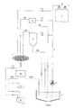
- the pulp 1 contained in the pit 2, through a pump 3, is thrusted through the duct 4 up to the sprays 5, which sprinkle the block of granite 6 being cut.
- a magnetic iron-removal apparatus 10 is connected onto a branch, equipped with the intercept valve 7.1, of the duct 4 of the pulp.
- the cyclone 8 separates the pulp going in, regulated by the intercept valve 7.3, into two flows:
- the magnetic iron-removal apparatus 10 separates the pulp going in, regulated by the valve 7.1, into two flows:
- the two flows 8A and 10A, of the cyclone 8 and of the magnetic iron-removal apparatus 10 respectively, are conveyed onto a vibrating sieve 11, which takes care of the mechanical separation of the particles present in the two flows, of a size greater than 0.3-0.4 mm, from the rest of the mixture, which is discharged into the collection tank 12.
- the plant foresees that the flow "9A" of the control apparatus 9 is also conveyed onto the vibrating sieve 11 so as to recover, after measuring, the possible large shots "Gr”, which have not been discharged with the flow "9B” of the "wet iron", which is conveyed directly into the pit 2.
- the iron-removal apparatus 20 positioned downstream of the vibrating sieve 11, collects all of the pulp that is not held by the sieving action of the vibrating sieve 11, i.e. the particles of a size smaller than 0.3-0.4 mm, that is fine shots "Gf", waste from the blades "S1", non-metallic abrasive substance "A”, granite dust "Sg” and water “H” and divides it into two flows:
- the iron-removal apparatus 30 again positioned downstream of the vibrating sieve 11, of the type that has two sieving chambers, is fed only by the flow of the pulp conveyed by the branch regulated by the valve 7.1 and divides it into two flows:
Landscapes
- Engineering & Computer Science (AREA)
- Mechanical Engineering (AREA)
- Mining & Mineral Resources (AREA)
- Environmental & Geological Engineering (AREA)
- Water Supply & Treatment (AREA)
- Chemical & Material Sciences (AREA)
- Organic Chemistry (AREA)
- Hydrology & Water Resources (AREA)
- Life Sciences & Earth Sciences (AREA)
- Paper (AREA)
- Separation Of Solids By Using Liquids Or Pneumatic Power (AREA)
- Cyclones (AREA)
- Oscillators With Electromechanical Resonators (AREA)
- Polarising Elements (AREA)
- Grinding-Machine Dressing And Accessory Apparatuses (AREA)
- Disintegrating Or Milling (AREA)
Abstract
Description
- fig. 1 (Table I) represents a diagram of a first embodiment of the unit, for realising the process according to the finding;
- fig. 2 (Table II) represents a diagram of a second embodiment of the unit, for realising the process according to the finding;
- fig. 3 (Table III) represents a diagram of a third embodiment of the unit, for realising the process according to the finding;
- a first over
flow 8A consisting of fine shots "Gf", waste from the blades "S1", a lot of water "H", almost all of the granite dust "Sg" and almost all of the non-metallic abrasive substance "A", if present; - a second under
flow 8B with the outlet of the large fraction, consisting almost entirely of large shots "Gr", a little water "H" and a little granite dust "Sg", which is conveyed directly into thepit 2 and put back into circulation by the circulation pump.
- a
first flow 10A, that collects all of the metallic component present in the mixture, i.e. the shots, fine and large "Gf+Gr" and the waste from the blades "S1"; - a
second flow 10B, which collects the mixture thus purified, thus containing water "H", granite dust "Sg" and non-metallic abrasive substance "A", which is conveyed directly into the pit and put back into circulation.
- a
first flow 20A, which collects the metallic component of a size smaller than 0.3-0.4 mm, which can be collected in aniron collection container 13 or discharged into thecollection tank 12; - a
second flow 20B, which collects all of the mixture, without the metallic component, which is sent to thepit 2 for recirculation.
- a
first flow 30A, which collects the mixture without the metallic component and which is sent to thepit 2; - a
second flow 30B, made up of the metallic component, consisting of fine shots and waste from the blades (Gf+Sl) which is sent into thecollection tank 12.
Claims (11)
- PROCESS FOR THE CORRECTION TREATMENT OF THE PULP IN A GRANITE-CUTTING UNIT, of the type in which the pulp (1), contained in the pit (2), through the pump (3), is thrusted through the duct (4), up to the sprays (5), which sprinkle the block of granite (6) being cut, wherein branches equipped with intercept valves (7) are applied onto the duct (4), to which branches a drainage apparatus, such as a cyclone (8) and the control apparatus (9) are connected,
said process being characterised in that
the specific weight value of the pulp can be changed, to take it back to optimal values, without changing the optimal value of the viscosity of the pulp itself. - PROCESS FOR THE CORRECTION TREATMENT OF THE PULP IN A GRANITE-CUTTING UNIT, according to claim 1, characterised in that it foresees the use of a magnetic iron-removal apparatus (10, 20, 30) applied on a branch, regulated by the intercept valve (7.1), of the delivery duct (4).
- PROCESS FOR THE CORRECTION TREATMENT OF THE PULP IN A GRANITE-CUTTING UNIT, according to claim 2, characterised in that it foresees the use of a vibrating sieve (11) for the recovery of the large shots and of the non-metallic abrasive substance.
- PROCESS FOR THE CORRECTION TREATMENT OF THE PULP IN A GRANITE-CUTTING UNIT, according to claims 2 and 3, characterised in that the iron-removal apparatus (10) is placed upstream of the vibrating sieve (11).
- PROCESS FOR THE CORRECTION TREATMENT OF THE PULP IN A GRANITE-CUTTING UNIT, according to claims 2 and 3, characterised in that the iron-removal apparatus (20, 30) is placed downstream of the vibrating sieve (11).
- PROCESS FOR THE CORRECTION TREATMENT OF THE PULP IN A GRANITE-CUTTING UNIT, according to claim 4, characterised in that the magnetic iron-removal apparatus (10) separates the pulp going in into two flows: a first flow 10A, that collects all of the metallic component present in the mixture, i.e. the shots, fine and large and the waste from the blades and a second flow 10B, consisting of the mixture thus purified, thus containing water, granite dust and part of the non-metallic abrasive substance, which may have been added, which is conveyed directly into the pit (2) and put back into circulation.
- PROCESS FOR THE CORRECTION TREATMENT OF THE PULP IN A GRANITE-CUTTING UNIT, according to claim 6, characterised in that the flow (10A) going out from the magnetic iron-removal apparatus (10) is conveyed onto the vibrating sieve (11), which takes care of the mechanical separation of the metallic particles constituting the large shots, which are of a size greater than 0.3-0.4 mm from the rest of the mixture.
- PROCESS FOR THE CORRECTION TREATMENT OF THE PULP IN A GRANITE-CUTTING UNIT, according to one or more of the previous claims, characterised in that the flows (8A) and (9A) going out, respectively, from the cyclone (8) and from the control apparatus (9), are conveyed onto the vibrating sieve (11), which takes care of holding the particles, mainly consisting of large shots, of a size greater than 0.3-0.4 mm.
- PROCESS FOR THE CORRECTION TREATMENT OF THE PULP IN A GRANITE-CUTTING UNIT, according to claim 5, characterised in that it foresees a branch, intercepted by the valve (7.1), which conveys a flow of pulp directly from the duct (4) to the vibrating sieve (11).
- PROCESS FOR THE CORRECTION TREATMENT OF THE PULP IN A GRANITE-CUTTING UNIT, according to claim 9, characterised in that the iron-removal apparatus (20), positioned downstream of the vibrating sieve (11), collects all of the pulp that is not held by the sieving action of the vibrating sieve, i.e. the particles of a size smaller than 0.3-0.4 mm, that is fine shots, waste from the blades, non-metallic abrasive substance, granite dust and water and takes care of dividing it into two flows: a first flow (20A), which collects the metallic component of a size smaller than 0.3-0.4 mm, which can be collected in an iron collection container (13) or discharged into the collection tank (12) and a second flow (20B), which collects all of the mixture, without the metallic component, which is sent to the pit (2) for recirculation.
- PROCESS FOR THE CORRECTION TREATMENT OF THE PULP IN A GRANITE-CUTTING UNIT, according to claim 9, characterised in that the iron-removal apparatus (30), positioned downstream of the vibrating sieve (11), of the type that has two sieving chambers, is fed only by the flow of pulp conveyed by the branch regulated by the valve (7.1) and divides it into two flows: a first flow (30A), which collects the mixture without the metallic component and which is sent to the pit (2) and a second flow (30B), made up of the metallic component containing fine shots and waste from the blades, which is sent into the collection tank (12).
Applications Claiming Priority (2)
| Application Number | Priority Date | Filing Date | Title |
|---|---|---|---|
| ITVI20030113 | 2003-06-10 | ||
| IT000113A ITVI20030113A1 (en) | 2003-06-10 | 2003-06-10 | PROCEDURE FOR THE CORRECTION TREATMENT OF THE |
Publications (4)
| Publication Number | Publication Date |
|---|---|
| EP1486308A2 true EP1486308A2 (en) | 2004-12-15 |
| EP1486308A3 EP1486308A3 (en) | 2005-07-20 |
| EP1486308B1 EP1486308B1 (en) | 2009-05-13 |
| EP1486308B8 EP1486308B8 (en) | 2009-08-19 |
Family
ID=33187407
Family Applications (1)
| Application Number | Title | Priority Date | Filing Date |
|---|---|---|---|
| EP04013302A Expired - Lifetime EP1486308B8 (en) | 2003-06-10 | 2004-06-05 | Process for the correction treatment of the pulp in a granite-cutting unit |
Country Status (6)
| Country | Link |
|---|---|
| EP (1) | EP1486308B8 (en) |
| AT (1) | ATE431233T1 (en) |
| BR (1) | BRPI0402287B1 (en) |
| DE (1) | DE602004021063D1 (en) |
| ES (1) | ES2326533T3 (en) |
| IT (1) | ITVI20030113A1 (en) |
Cited By (3)
| Publication number | Priority date | Publication date | Assignee | Title |
|---|---|---|---|---|
| ITBG20090053A1 (en) * | 2009-10-13 | 2011-04-14 | Fil Tec S R L | SYSTEM AND METHOD FOR FILTERING THE WASTE WATER DERIVING FROM THE CUTTING OF BLOCKS AND POLISHING OF MARBLES, GRANITES AND SIMILARS. |
| JP2018108632A (en) * | 2017-01-03 | 2018-07-12 | エスケー シルトロン カンパニー リミテッド | Wafer polishing system |
| WO2019206445A1 (en) | 2018-04-27 | 2019-10-31 | Karlsruher Institut Für Technologie (Kit) | Separating installation and separating method |
Family Cites Families (6)
| Publication number | Priority date | Publication date | Assignee | Title |
|---|---|---|---|---|
| FR2578470A1 (en) * | 1985-03-05 | 1986-09-12 | Materiel Sabliere Sarl | Process and device for recycling abrasive in stone sawing installations |
| IT1238882B (en) * | 1990-02-28 | 1993-09-04 | Giorgini Maggi Srl | PROCEDURE FOR THE WASHING AND CHECKING OF THE COMPOSITION OF ABRASIVE TURBIDES USED IN THE CUTTING OF GRANITES AND SIMILAR STONES AND RELATED EQUIPMENT. |
| IT1243073B (en) * | 1990-10-04 | 1994-05-23 | Technostone Ind S P A | Method and equipment for sawing stone materials |
| FR2704455B1 (en) * | 1993-04-28 | 1995-07-21 | Stratech International | Process for recovering sludge from sawing, cutting and polishing granite blocks. |
| US5799643A (en) * | 1995-10-04 | 1998-09-01 | Nippei Toyama Corp | Slurry managing system and slurry managing method for wire saws |
| ITTV20010155A1 (en) * | 2001-11-27 | 2003-05-27 | Pometon S P A | PROCEDURE FOR OBTAINING AN ABRASIVE MIXTURE PARTICULARLY FOR SEGMENT OF MARBLES AND PRODUCT SO OBTAINED |
-
2003
- 2003-06-10 IT IT000113A patent/ITVI20030113A1/en unknown
-
2004
- 2004-06-03 BR BRPI0402287-4A patent/BRPI0402287B1/en not_active IP Right Cessation
- 2004-06-05 EP EP04013302A patent/EP1486308B8/en not_active Expired - Lifetime
- 2004-06-05 DE DE602004021063T patent/DE602004021063D1/en not_active Expired - Fee Related
- 2004-06-05 AT AT04013302T patent/ATE431233T1/en not_active IP Right Cessation
- 2004-06-05 ES ES04013302T patent/ES2326533T3/en not_active Expired - Lifetime
Cited By (5)
| Publication number | Priority date | Publication date | Assignee | Title |
|---|---|---|---|---|
| ITBG20090053A1 (en) * | 2009-10-13 | 2011-04-14 | Fil Tec S R L | SYSTEM AND METHOD FOR FILTERING THE WASTE WATER DERIVING FROM THE CUTTING OF BLOCKS AND POLISHING OF MARBLES, GRANITES AND SIMILARS. |
| JP2018108632A (en) * | 2017-01-03 | 2018-07-12 | エスケー シルトロン カンパニー リミテッド | Wafer polishing system |
| US10525568B2 (en) | 2017-01-03 | 2020-01-07 | Sk Siltron Co., Ltd. | Wafer polishing system |
| WO2019206445A1 (en) | 2018-04-27 | 2019-10-31 | Karlsruher Institut Für Technologie (Kit) | Separating installation and separating method |
| US11865550B2 (en) | 2018-04-27 | 2024-01-09 | Karlsruher Institut Fuer Technologie (Kit) | Separating installation and separating method |
Also Published As
| Publication number | Publication date |
|---|---|
| EP1486308A3 (en) | 2005-07-20 |
| BRPI0402287B1 (en) | 2015-06-09 |
| EP1486308B8 (en) | 2009-08-19 |
| DE602004021063D1 (en) | 2009-06-25 |
| EP1486308B1 (en) | 2009-05-13 |
| BRPI0402287A (en) | 2005-06-14 |
| ATE431233T1 (en) | 2009-05-15 |
| ES2326533T3 (en) | 2009-10-14 |
| ITVI20030113A1 (en) | 2004-12-11 |
Similar Documents
| Publication | Publication Date | Title |
|---|---|---|
| CN101439500B (en) | Blasting method and blasting machine | |
| CN100469535C (en) | Method and device for abrasive recovery and waste separation system | |
| US4872975A (en) | System for separating abrasive material from a fluid used in fluid jet cutting | |
| JP7078512B2 (en) | How to collect dihydrate gypsum from waste gypsum board | |
| US5110454A (en) | Apparatus for reclaiming gravel, soil particles and wood pieces from a mixture of the same | |
| SU663321A3 (en) | Method of washing chips and device for effecting same | |
| CN103801151A (en) | Apparatus and method for de-watering of slurries | |
| NO329533B1 (en) | Method and apparatus for removing drill cuttings from drilling fluid | |
| EA036141B1 (en) | Method for recycling abrasive used for high pressure waterjet cutting from cutting sludge and equipment for application of this method | |
| CN110404613A (en) | A kind of rice scourer | |
| AU2008204675B2 (en) | Density-based coke separation process in paste plant | |
| EP0935513A2 (en) | Method and device for recycling abrasive agents used in water jet cutting | |
| US5240114A (en) | Process for reclaiming gravel, soil particles, and wood pieces from a mixture of the same | |
| EP1486308B1 (en) | Process for the correction treatment of the pulp in a granite-cutting unit | |
| US20040154961A1 (en) | Mehtod and device for separating fractions in a material flow | |
| RU2673893C2 (en) | Shaker table apparatus, components thereof and method of use | |
| NO831049L (en) | PREVENTION FOR CLASSIFICATION OF SAND | |
| CN1248924A (en) | Coagulation precipitator | |
| RU2728001C1 (en) | Process scheme of spent garnet sand regeneration from hydro-abrasive cutting | |
| JPH07148665A (en) | Waste liquid disposal device for water jet machining device | |
| CA3098660C (en) | Method and apparatus for washing and grading sand | |
| EP3088367B1 (en) | Method for cleaning water collected in a polymer plant | |
| JP2005256334A (en) | Sand gathering machine with classifier and classifier for suspended carbons | |
| TW201127555A (en) | Grinding slurry circulation device of wirw saw | |
| KR20100071276A (en) | Manufacturing apparatus of fine aggregate using stone and manufacturing method of the same |
Legal Events
| Date | Code | Title | Description |
|---|---|---|---|
| PUAI | Public reference made under article 153(3) epc to a published international application that has entered the european phase |
Free format text: ORIGINAL CODE: 0009012 |
|
| AK | Designated contracting states |
Kind code of ref document: A2 Designated state(s): AT BE BG CH CY CZ DE DK EE ES FI FR GB GR HU IE IT LI LU MC NL PL PT RO SE SI SK TR |
|
| AX | Request for extension of the european patent |
Extension state: AL HR LT LV MK |
|
| PUAL | Search report despatched |
Free format text: ORIGINAL CODE: 0009013 |
|
| AK | Designated contracting states |
Kind code of ref document: A3 Designated state(s): AT BE BG CH CY CZ DE DK EE ES FI FR GB GR HU IE IT LI LU MC NL PL PT RO SE SI SK TR |
|
| AX | Request for extension of the european patent |
Extension state: AL HR LT LV MK |
|
| 17P | Request for examination filed |
Effective date: 20060111 |
|
| AKX | Designation fees paid |
Designated state(s): AT BE BG CH CY CZ DE DK EE ES FI FR GB GR HU IE IT LI LU MC NL PL PT RO SE SI SK TR |
|
| GRAP | Despatch of communication of intention to grant a patent |
Free format text: ORIGINAL CODE: EPIDOSNIGR1 |
|
| GRAS | Grant fee paid |
Free format text: ORIGINAL CODE: EPIDOSNIGR3 |
|
| GRAA | (expected) grant |
Free format text: ORIGINAL CODE: 0009210 |
|
| AK | Designated contracting states |
Kind code of ref document: B1 Designated state(s): AT BE BG CH CY CZ DE DK EE ES FI FR GB GR HU IE IT LI LU MC NL PL PT RO SE SI SK TR |
|
| REG | Reference to a national code |
Ref country code: GB Ref legal event code: FG4D |
|
| REG | Reference to a national code |
Ref country code: CH Ref legal event code: EP |
|
| REG | Reference to a national code |
Ref country code: IE Ref legal event code: FG4D |
|
| RAP2 | Party data changed (patent owner data changed or rights of a patent transferred) |
Owner name: MARMI ZENATELLI S.R.L. |
|
| REF | Corresponds to: |
Ref document number: 602004021063 Country of ref document: DE Date of ref document: 20090625 Kind code of ref document: P |
|
| NLT2 | Nl: modifications (of names), taken from the european patent patent bulletin |
Owner name: MARMI ZENATELLI S.R.L. Effective date: 20090617 |
|
| REG | Reference to a national code |
Ref country code: ES Ref legal event code: FG2A Ref document number: 2326533 Country of ref document: ES Kind code of ref document: T3 |
|
| PG25 | Lapsed in a contracting state [announced via postgrant information from national office to epo] |
Ref country code: PT Free format text: LAPSE BECAUSE OF FAILURE TO SUBMIT A TRANSLATION OF THE DESCRIPTION OR TO PAY THE FEE WITHIN THE PRESCRIBED TIME-LIMIT Effective date: 20090913 Ref country code: FI Free format text: LAPSE BECAUSE OF FAILURE TO SUBMIT A TRANSLATION OF THE DESCRIPTION OR TO PAY THE FEE WITHIN THE PRESCRIBED TIME-LIMIT Effective date: 20090513 Ref country code: AT Free format text: LAPSE BECAUSE OF FAILURE TO SUBMIT A TRANSLATION OF THE DESCRIPTION OR TO PAY THE FEE WITHIN THE PRESCRIBED TIME-LIMIT Effective date: 20090513 |
|
| NLV1 | Nl: lapsed or annulled due to failure to fulfill the requirements of art. 29p and 29m of the patents act | ||
| PG25 | Lapsed in a contracting state [announced via postgrant information from national office to epo] |
Ref country code: SE Free format text: LAPSE BECAUSE OF FAILURE TO SUBMIT A TRANSLATION OF THE DESCRIPTION OR TO PAY THE FEE WITHIN THE PRESCRIBED TIME-LIMIT Effective date: 20090813 Ref country code: NL Free format text: LAPSE BECAUSE OF FAILURE TO SUBMIT A TRANSLATION OF THE DESCRIPTION OR TO PAY THE FEE WITHIN THE PRESCRIBED TIME-LIMIT Effective date: 20090513 Ref country code: PL Free format text: LAPSE BECAUSE OF FAILURE TO SUBMIT A TRANSLATION OF THE DESCRIPTION OR TO PAY THE FEE WITHIN THE PRESCRIBED TIME-LIMIT Effective date: 20090513 Ref country code: SI Free format text: LAPSE BECAUSE OF FAILURE TO SUBMIT A TRANSLATION OF THE DESCRIPTION OR TO PAY THE FEE WITHIN THE PRESCRIBED TIME-LIMIT Effective date: 20090513 |
|
| PG25 | Lapsed in a contracting state [announced via postgrant information from national office to epo] |
Ref country code: DK Free format text: LAPSE BECAUSE OF FAILURE TO SUBMIT A TRANSLATION OF THE DESCRIPTION OR TO PAY THE FEE WITHIN THE PRESCRIBED TIME-LIMIT Effective date: 20090513 Ref country code: RO Free format text: LAPSE BECAUSE OF FAILURE TO SUBMIT A TRANSLATION OF THE DESCRIPTION OR TO PAY THE FEE WITHIN THE PRESCRIBED TIME-LIMIT Effective date: 20090513 Ref country code: CZ Free format text: LAPSE BECAUSE OF FAILURE TO SUBMIT A TRANSLATION OF THE DESCRIPTION OR TO PAY THE FEE WITHIN THE PRESCRIBED TIME-LIMIT Effective date: 20090513 Ref country code: MC Free format text: LAPSE BECAUSE OF NON-PAYMENT OF DUE FEES Effective date: 20090630 Ref country code: EE Free format text: LAPSE BECAUSE OF FAILURE TO SUBMIT A TRANSLATION OF THE DESCRIPTION OR TO PAY THE FEE WITHIN THE PRESCRIBED TIME-LIMIT Effective date: 20090513 |
|
| REG | Reference to a national code |
Ref country code: CH Ref legal event code: PL |
|
| PG25 | Lapsed in a contracting state [announced via postgrant information from national office to epo] |
Ref country code: BE Free format text: LAPSE BECAUSE OF FAILURE TO SUBMIT A TRANSLATION OF THE DESCRIPTION OR TO PAY THE FEE WITHIN THE PRESCRIBED TIME-LIMIT Effective date: 20090513 Ref country code: SK Free format text: LAPSE BECAUSE OF FAILURE TO SUBMIT A TRANSLATION OF THE DESCRIPTION OR TO PAY THE FEE WITHIN THE PRESCRIBED TIME-LIMIT Effective date: 20090513 |
|
| PLBE | No opposition filed within time limit |
Free format text: ORIGINAL CODE: 0009261 |
|
| STAA | Information on the status of an ep patent application or granted ep patent |
Free format text: STATUS: NO OPPOSITION FILED WITHIN TIME LIMIT |
|
| REG | Reference to a national code |
Ref country code: FR Ref legal event code: ST Effective date: 20100226 |
|
| PG25 | Lapsed in a contracting state [announced via postgrant information from national office to epo] |
Ref country code: BG Free format text: LAPSE BECAUSE OF FAILURE TO SUBMIT A TRANSLATION OF THE DESCRIPTION OR TO PAY THE FEE WITHIN THE PRESCRIBED TIME-LIMIT Effective date: 20090813 |
|
| 26N | No opposition filed |
Effective date: 20100216 |
|
| GBPC | Gb: european patent ceased through non-payment of renewal fee |
Effective date: 20090813 |
|
| PG25 | Lapsed in a contracting state [announced via postgrant information from national office to epo] |
Ref country code: LI Free format text: LAPSE BECAUSE OF NON-PAYMENT OF DUE FEES Effective date: 20090630 Ref country code: CH Free format text: LAPSE BECAUSE OF NON-PAYMENT OF DUE FEES Effective date: 20090630 Ref country code: IE Free format text: LAPSE BECAUSE OF NON-PAYMENT OF DUE FEES Effective date: 20090605 Ref country code: FR Free format text: LAPSE BECAUSE OF NON-PAYMENT OF DUE FEES Effective date: 20090715 |
|
| PG25 | Lapsed in a contracting state [announced via postgrant information from national office to epo] |
Ref country code: DE Free format text: LAPSE BECAUSE OF NON-PAYMENT OF DUE FEES Effective date: 20100101 |
|
| PG25 | Lapsed in a contracting state [announced via postgrant information from national office to epo] |
Ref country code: GR Free format text: LAPSE BECAUSE OF FAILURE TO SUBMIT A TRANSLATION OF THE DESCRIPTION OR TO PAY THE FEE WITHIN THE PRESCRIBED TIME-LIMIT Effective date: 20090814 |
|
| PG25 | Lapsed in a contracting state [announced via postgrant information from national office to epo] |
Ref country code: GB Free format text: LAPSE BECAUSE OF NON-PAYMENT OF DUE FEES Effective date: 20090813 |
|
| PG25 | Lapsed in a contracting state [announced via postgrant information from national office to epo] |
Ref country code: LU Free format text: LAPSE BECAUSE OF NON-PAYMENT OF DUE FEES Effective date: 20090605 |
|
| PG25 | Lapsed in a contracting state [announced via postgrant information from national office to epo] |
Ref country code: HU Free format text: LAPSE BECAUSE OF FAILURE TO SUBMIT A TRANSLATION OF THE DESCRIPTION OR TO PAY THE FEE WITHIN THE PRESCRIBED TIME-LIMIT Effective date: 20091114 |
|
| PG25 | Lapsed in a contracting state [announced via postgrant information from national office to epo] |
Ref country code: TR Free format text: LAPSE BECAUSE OF FAILURE TO SUBMIT A TRANSLATION OF THE DESCRIPTION OR TO PAY THE FEE WITHIN THE PRESCRIBED TIME-LIMIT Effective date: 20090513 |
|
| PG25 | Lapsed in a contracting state [announced via postgrant information from national office to epo] |
Ref country code: CY Free format text: LAPSE BECAUSE OF FAILURE TO SUBMIT A TRANSLATION OF THE DESCRIPTION OR TO PAY THE FEE WITHIN THE PRESCRIBED TIME-LIMIT Effective date: 20090513 |
|
| PGFP | Annual fee paid to national office [announced via postgrant information from national office to epo] |
Ref country code: ES Payment date: 20120629 Year of fee payment: 9 |
|
| REG | Reference to a national code |
Ref country code: ES Ref legal event code: FD2A Effective date: 20151204 |
|
| PGFP | Annual fee paid to national office [announced via postgrant information from national office to epo] |
Ref country code: IT Payment date: 20150629 Year of fee payment: 12 |
|
| PG25 | Lapsed in a contracting state [announced via postgrant information from national office to epo] |
Ref country code: ES Free format text: LAPSE BECAUSE OF NON-PAYMENT OF DUE FEES Effective date: 20140606 |
|
| PG25 | Lapsed in a contracting state [announced via postgrant information from national office to epo] |
Ref country code: IT Free format text: LAPSE BECAUSE OF NON-PAYMENT OF DUE FEES Effective date: 20160605 |