EP1486257A2 - Spiral nozzle - Google Patents
Spiral nozzle Download PDFInfo
- Publication number
- EP1486257A2 EP1486257A2 EP04253445A EP04253445A EP1486257A2 EP 1486257 A2 EP1486257 A2 EP 1486257A2 EP 04253445 A EP04253445 A EP 04253445A EP 04253445 A EP04253445 A EP 04253445A EP 1486257 A2 EP1486257 A2 EP 1486257A2
- Authority
- EP
- European Patent Office
- Prior art keywords
- central axis
- spiral
- spiral nozzle
- spray guide
- liquid
- Prior art date
- Legal status (The legal status is an assumption and is not a legal conclusion. Google has not performed a legal analysis and makes no representation as to the accuracy of the status listed.)
- Withdrawn
Links
Images




Classifications
-
- B—PERFORMING OPERATIONS; TRANSPORTING
- B05—SPRAYING OR ATOMISING IN GENERAL; APPLYING FLUENT MATERIALS TO SURFACES, IN GENERAL
- B05B—SPRAYING APPARATUS; ATOMISING APPARATUS; NOZZLES
- B05B1/00—Nozzles, spray heads or other outlets, with or without auxiliary devices such as valves, heating means
- B05B1/02—Nozzles, spray heads or other outlets, with or without auxiliary devices such as valves, heating means designed to produce a jet, spray, or other discharge of particular shape or nature, e.g. in single drops, or having an outlet of particular shape
-
- B—PERFORMING OPERATIONS; TRANSPORTING
- B05—SPRAYING OR ATOMISING IN GENERAL; APPLYING FLUENT MATERIALS TO SURFACES, IN GENERAL
- B05B—SPRAYING APPARATUS; ATOMISING APPARATUS; NOZZLES
- B05B1/00—Nozzles, spray heads or other outlets, with or without auxiliary devices such as valves, heating means
- B05B1/26—Nozzles, spray heads or other outlets, with or without auxiliary devices such as valves, heating means with means for mechanically breaking-up or deflecting the jet after discharge, e.g. with fixed deflectors; Breaking-up the discharged liquid or other fluent material by impinging jets
- B05B1/262—Nozzles, spray heads or other outlets, with or without auxiliary devices such as valves, heating means with means for mechanically breaking-up or deflecting the jet after discharge, e.g. with fixed deflectors; Breaking-up the discharged liquid or other fluent material by impinging jets with fixed deflectors
Definitions
- the present invention relates to a spiral nozzle.
- the flue gas which is discharged, for example, from the boiler of a thermal power plant using coal as fuel, contains a sulfur component.
- a sulfur component contained in the flue gas
- desulfurization equipment is therefore installed in thermal power plants and the like.
- three processes a wet process, a dry process, and a semi-dry process, are generally used in this desulfurization equipment.
- desulfurization equipment using the wet process sprays droplets of an alkaline solution containing calcium carbonate into the flue gas, to thereby neutralize the sulfur component of the flue gas with the alkaline component, and at the same time absorb the sulfur component in the droplets of alkaline solution, and thus remove the sulfur component from the flue gas.
- a hollow cone, full cone, or spiral nozzle is normally used in the desulfurization equipment to spray droplets of the alkaline solution.
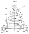
- the spiral nozzle as shown in FIGS. 1 and 2, comprises a spray guide 100 which is formed in a helix converging towards its own central axis L, and a support part 200 which is formed integral with one end of the non-converging side of the spray guide 100, and formed with a conduit port 210 for passing an alkaline solution.
- FIG. 2 is a view of the spiral nozzle in FIG. 1 as seen from the left horizontal direction.
- the spray guide 100 is formed in three coil parts 110, 120, and 130 connected in the central axis L direction, in other words, in a three-tiered coil structure.
- the bottom faces of the coil parts 110, 120, and 130 are formed as liquid impingement faces 111, 121, and 131, which are set so that the angle of each with respect to the central axis L differs.
- the entirety of each the liquid impingement faces 111, 121, and 131 is set at a fixed angle with respect to the central axis L.
- the support part 200 is formed integral with one end of the coil part 130, in other words, with one end on the non-converging side of the spray guide 100, and a flange 300 is formed integral with its own end (bottom end in FIG. 1 and FIG. 2).
- the spiral nozzle configured in this manner is fixed to a supply device (not shown in drawings) which supplies an alkaline solution to the spiral nozzle at a predetermined pressure, by a support plate 400 formed separate from the spiral nozzle and having through holes 410 penetrated by bolts or screws. More specifically, a support plate flange 420 is formed on the support plate 400, and as shown in the drawing, the support plate flange 420 and the flange 300 are joined with adhesive, and the support plate 400 is fixed to the supply device with the bolts 500, thus fixing the spiral nozzle to the supply device. Moreover, the spray guide 100, the support part 200, and the flange 300 are formed of a ceramic material to prevent corrosion by the alkaline solution. Furthermore, plastic is used for the support plate 400, and metal is used for the bolts 500.
- the alkaline solution discharged from the supply device is supplied to the spray guide 100 via the conduit port 210.
- the alkaline solution then impinges on the liquid impingement faces 111, 121, and 131, thus forming fine droplets which are sprayed to the outside.
- FIG. 3 shows schematically the distribution pattern (hereafter referred to as the 'spray pattern') in a plane perpendicular to the central axis L, of the alkaline solution sprayed from the spiral nozzle.
- the alkaline solution is distributed in three concentric circles. This is due to the spray guide 100 having a three-tiered coil structure as explained above, wherein the three coil parts 110, 120, and 130 having the liquid impingement faces 111, 121, and 131 are connected inclined each at different angles.
- 'Spray guide' and 'spray pattern' are terms normally used in this technical field, and the term 'spray' as used here refers to an aggregation of droplets having a particle size of, for example, a few millimeters.
- Patent document 1 Japanese Unexamined Patent Application, First Publication No. Sho 63-111954
- Patent document 2 Japanese Unexamined Patent Application, First Publication No. Hei 9-57155
- Patent document 3 Japanese Unexamined Patent Application, First Publication No. Hei 9-57155
- the coil parts 110, 120, and 130 have the liquid impingement faces 111, 121, and 131, each inclined at different angles, then at a connection site A of the coil part 110 and the coil part 120 and a connection site B of the coil part 120 and the coil part 130, there is naturally formed an inclined face 'a' connecting the liquid impingement faces 111 and 121, and an inclined face 'b' connecting the liquid impingement faces 121 and 131. Formation of these inclined faces 'a' and 'b' results in an increase in the overall length of the spiral nozzle, increasing the amount of material required for formation of the spiral nozzle, and inviting an increase in manufacturing costs.
- the spiral nozzle is formed of a ceramic material, even a small increase in the amount of material results in a particular increase in manufacturing cost. Moreover, an increase in the overall length of the nozzle results in a reduction in the number able to be inserted in the furnace for firing, an increase in defects due to collapse, and a consequent further increase in manufacturing cost.
- the spray pattern of this type of spiral nozzle is distributed in three concentric circles. Therefore spray patterns a1 and b1 occur naturally to connect the individual concentric spray patterns in order to ensure that the individual concentric spray patterns are contiguous.
- the spray patterns a1 and b1 occur due to the inclined faces 'a' and 'b', and the overall spray pattern becomes nonuniform due to the occurrence of the spray patterns a1 and b1.
- the flow rate of the alkaline solution sprayed from the spiral nozzle is locally increased, and the sulfur component can no longer be uniformly removed from the flue gas.
- the flange 300 and the support plate 400 are currently joined with adhesive. Therefore in some environments the adhesive deteriorates, with the possibility of a reduction in life of the spiral nozzle. If the life of the spiral nozzle is reduced, the spiral nozzle must be replaced each time, and the number of replacements is thus increased, so that the maintenance cost of the desulfurization equipment is increased.
- the present invention takes into consideration the aforementioned problems, with an object of addressing the following points: (1) uniform treatment by uniform spraying of the solution; (2) a reduction in the manufacturing cost of the spiral nozzle by reducing the amount of material forming the spiral nozzle, and the length of the spiral nozzle; (3) a reduction in the manufacturing cost of the equipment incorporating the spiral nozzle by reducing the number of installed spiral nozzles; and (4) a reduction in the maintenance cost of the equipment incorporating the spiral nozzle by extending the life of the spiral nozzle.
- the present invention adopts as a first means a configuration where, in a spiral nozzle which sprays droplets of a liquid from a spray guide formed in a helix converging towards its own central axis, the spray guide has a liquid impingement face inclined at a predetermined angle with respect to the central axis so that a distribution pattern of the liquid in a plane perpendicular to the central axis is in the form of a spiral shape.
- the distribution pattern of the liquid has a spiral shape winding at approximately equal spaced pitch.
- a third means there is adopted a configuration where, in either one of the first and second means, a surface on the central axis side of the spray guide is specified by a surface of a rotating body obtained by rotating an arc having a predetermined radius with respect to the central axis.
- a fifth means there is adopted a configuration where, in a spiral nozzle having a spray guide formed in a helix converging towards its own central axis, and a support part formed integral with an other end of the spray guide and in which is formed a conduit port for passing a liquid, and which sprays droplets of a liquid from the spray guide, a comer being a site of connection of the spray guide and the support part and a site of the start of the spray guide, is formed along an arc having a predetermined radius.
- a seventh means there is adopted a configuration where either one of the fifth and sixth means has a flange formed integral with the support part and formed with through holes that are penetrated by bolts or screws.
- FIG. 4 is a front view of the spiral nozzle according to this embodiment
- FIG. 5 is a side view from the left of the spiral nozzle in FIG. 4.
- the spiral nozzle according to this embodiment is provided with a spray guide 1 formed in a helix converging towards its own central axis L, a support part 2 formed integral with one end (the base) on the non-converging side of the spray guide 1 and with a conduit port 21 for passing an alkaline solution, and a flange 3 formed integral with one end of the support part 2 (bottom end in FIG. 4 and FIG. 5), all of these components being formed integral. All components of this spiral nozzle (the spray guide 1, the support part 2, and the flange 3) are formed integral. Moreover they are formed of the same fired ceramic material (for example, Si-SiC) in order to ensure durability when used with an alkaline solution.
- the same fired ceramic material for example, Si-SiC
- the spray guide 1 comprises a single three-coil winding with its own bottom face (the face towards the base side) being formed as a liquid impingement face 11 and having an angle with respect to the central axis L specified for each part.
- the angle of the liquid impingement face 11 with respect to the central axis L is the angle formed between a line of intersection of a plane including the central axis L and the liquid impingement face 11, and the tip central axis L side (the converging side 1 (tip side) of the spray guide 1).
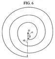
- Each part of the liquid impingement face 11 of the spiral nozzle according to the present invention is inclined at a predetermined angle to ensure that a spray pattern having a spiral shape with approximately equal pitch as shown in FIG. 6 is obtained.
- a liquid impingement face 11a at a start portion of the spray guide 1 is formed so that its angle A with the central axis L is 90°, and an angle B between a mid-part 11b of the first coil and a mid-part 11c of the first coil is 89°.
- the liquid impingement face 11 is inclined with respect to the central axis L so that; an angle C at a mid-part 11d of the second coil is 60°, an angle D at a mid-part 11e of the third coil is 45°, an angle E at a mid-part 11f of the third coil is 26°, and an angle F at the end of the third coil (tip of the spray guide 1) is 20°, and thus a spray pattern having a spiral shape winding at approximately equal pitch as shown in FIG. 6 is obtained.
- the spiral shape winding has an inside end S and an outside end E, and the radius of the spiral shape winding from the center O gradually increases from the inside end S (radius r1) to the outside end E (radius r2).
- the spray guide 1 By forming the spray guide 1 while specifying the angle with respect to the central axis L of the liquid impingement face 11 to ensure that the spray pattern has a spiral shape, the angle of the liquid impingement face 11 is gradually and continuously changed with respect to the central axis L.
- the inclined faces 'a' and 'b' of the conventional spiral nozzle as shown in FIGS. 1 and 2 are therefore not formed, and it is consequently possible to form the spiral nozzle of the present invention with a comparatively small amount of material.
- the face 12 on the central axis L side of the spray guide 1 is specified by the surface of a body of revolution obtained by rotating an arc of radius 500 mm with respect to the central axis L. Consequently the face 12 on the central axis L side of the spray guide 1 forms a curved surface expanded outwards. Therefore the space enclosed within the spray guide 1 increases, enabling supply of a larger volume of alkaline solution to the spray guide 1, and the spraying of a larger volume of alkaline solution from a single spiral nozzle than is conventionally the case.
- the face 12 on the central axis L side of the spray guide 1 is specified by the surface of a body of revolution obtained by rotating an arc having a radius within a range of greater than the diameter of the conduit port 21, and less than 2,000 mm.
- a comer C being the site of connection of the spray guide 1 and the support part 2 and the site of the start of the spray guide 1, is formed along an arc of radius 4 mm.
- This comer C becomes a stress concentration region when the alkaline solution is supplied to the spray guide 1 at a predetermined pressure.
- the stress can be dispersed, enabling an increase in the durability of the spiral nozzle.
- the wall of the spray guide 1 is thin.
- forming the comer C along an arc of a predetermined radius enables sufficient durability to be obtained.
- the corner C may be formed along an arc of a radius greater than 3mm. If the comer C is formed along an arc of a radius of less than 3mm, the stress loading on the comer C increases, and sufficient durability cannot be expected.
- through holes 31 are formed in the flange 3 for penetration of bolts (or screws) 5 to fasten together the spiral nozzle and a supply device (not shown in the drawings) which supplies the alkaline solution to the spiral nozzle at a predetermined pressure.
- the alkaline solution When the alkaline solution is supplied to the spiral nozzle configured in this manner from the supply device at a predetermined pressure, the alkaline solution is formed into liquid droplets by impinging on the liquid impingement face 11 of the spray guide 1, and a spray pattern having a spiral shape winding at approximately equal pitch is obtained.
- the alkaline solution can be distributed more uniformly, thus enabling an improvement in the desulfurization effect.
- Liquid was supplied at a pressure of 0.03MPa to a spiral nozzle according to the aforementioned embodiment, having an overall length of 200 mm, a length in the direction of the central axis L of the spray guide 1 of 145 mm, a diameter of the support part of 120 mm, and a diameter of the conduit port 21 of 100 mm, with the face 12 on the central axis side of the spray guide 1 specified by the surface of a body of revolution obtained by rotation of an arc of a radius of 500 mm with respect to the central axis L, a comer C formed along an arc of a radius of 4mm, and formed of Si-SiC having a modulus of elasticity of the overall body of 360 GPa, and a Poisson's ratio of 0.19.
- the flow rate of the liquid sprayed from the spiral nozzle was 2,800 L/min
- the stress loading on the corner C was 30MPa.
- liquid was supplied at a pressure of 0.03 MPa to a spiral nozzle according to the conventional technology, having an overall length of 250 mm, a length in the direction of the central axis L of the spray guide 1 of 180 mm, a diameter of the support part of 120 mm, and a diameter of the conduit port 21 of 100 mm, with the face 12 on the central axis side of the spray guide 1 specified by the surface of a body of revolution obtained by rotation of a straight line with respect to the central axis L, a comer C formed along an arc of a radius of 2 mm, and formed of Si-SiC having a modulus of elasticity of the overall body of 360 GPa, and a Poisson's ratio of 0.19.
- the flow rate of the liquid sprayed from the spiral nozzle was 2,000L/min
- the stress loading on the comer C was 38 MPa.
- the spiral nozzle is described as being installed in desulfurization equipment. However it is not restricted to this application, and may also be installed in dust settling equipment, and in gas cooling equipment. In such cases, the spiral nozzle need not be formed of a ceramic material.
- FIG. 7 is a drawing showing a spray pattern according to another embodiment of the present invention.
- the spray pattern shown in FIG. 6 the radius of the spiral shape winding from the center O gradually increases from the inside end S to the outside end E.
- the spray pattern shown in FIG. 7 has an inner spiral winding S-M and an outermost arc M-E.
- the radius of the inner spiral winding S-M from the center O gradually increases from the inside end S to the point M (radius r).
- the outermost arc M-E has a substantially constant radius r.
- the central angle 0 of the outermost arc M-E is not limited, but it is preferably between 180° and 360°. More preferably, the center angle ⁇ is between 225° and 315°.
- the outer periphery of the spray area has a shape near a complete circle, it is easy to arrange a plurality of the spray nozzles so as to obtain a uniform spray density.
- the spiral nozzle sprays liquid in droplets from the spray guide formed in a helix converging towards its own central axis L, and the spray guide has a liquid impingement face inclined at a predetermined angle so that the liquid distribution pattern in a plane perpendicular to the central axis L forms a spiral shape, and thus the liquid is sprayed uniformly, enabling uniform treatment.
Landscapes
- Nozzles (AREA)
Abstract
Description
Claims (9)
- A spiral nozzle for spraying droplets of a liquid, comprising a spray guide formed in a helix converging towards its own central axis, wherein said spray guide has a liquid impingement face inclined at a predetermined angle with respect to said central axis so that a distribution pattern of said liquid in a plane perpendicular to the central axis is in the form of a spiral shape.
- A spiral nozzle according to claim 1, wherein said distribution pattern of the liquid has a spiral shape winding at approximately equal spaced pitch.
- A spiral nozzle according to claim 1, wherein a surface on the central axis side of said spray guide is specified by a surface of a rotating body obtained by rotating an arc having a predetermined radius with respect to said central axis.
- A spiral nozzle according to claim 3, wherein said predetermined radius is less than 2,000 mm.
- A spiral nozzle having a spray guide formed in a helix converging at one end towards its own central axis, and a support part formed integral with an other end of said spray guide and in which is formed a conduit port for passing a liquid, and which sprays droplets of a liquid from said spray guide, wherein a comer being a site of connection of said spray guide and said support part and a site of the start of said spray guide, is formed along an arc having a predetermined radius.
- A spiral nozzle according to claim 5, wherein said predetermined radius is greater than 3 mm.
- A spiral nozzle according to claim 5, having a flange formed integral with said support part and formed with through holes that are penetrated by bolts or screws.
- A spiral nozzle according to claim 1 or 5, wherein all components are formed of the same ceramic material.
- A spiral nozzle according to claim 1 or 5, wherein the distribution pattern of said liquid in a plane perpendicular to the central axis is in the form of a spiral, the spiral has an inner spiral winding and an outermost arc, the radius of the inner spiral winding from the central axis gradually increases from an inside end toward the outermost arc, the outermost arc has a substantially constant radius, and an central angle of the outermost arc is more than 180°.
Applications Claiming Priority (2)
| Application Number | Priority Date | Filing Date | Title |
|---|---|---|---|
| JP2003168247A JP2005000837A (en) | 2003-06-12 | 2003-06-12 | Spiral nozzle |
| JP2003168247 | 2003-06-12 |
Publications (2)
| Publication Number | Publication Date |
|---|---|
| EP1486257A2 true EP1486257A2 (en) | 2004-12-15 |
| EP1486257A3 EP1486257A3 (en) | 2008-11-19 |
Family
ID=33296884
Family Applications (1)
| Application Number | Title | Priority Date | Filing Date |
|---|---|---|---|
| EP04253445A Withdrawn EP1486257A3 (en) | 2003-06-12 | 2004-06-10 | Spiral nozzle |
Country Status (6)
| Country | Link |
|---|---|
| US (1) | US20050001066A1 (en) |
| EP (1) | EP1486257A3 (en) |
| JP (1) | JP2005000837A (en) |
| CN (1) | CN1572373A (en) |
| SG (1) | SG127731A1 (en) |
| TW (1) | TW200507941A (en) |
Cited By (2)
| Publication number | Priority date | Publication date | Assignee | Title |
|---|---|---|---|---|
| EP3614077A1 (en) * | 2018-08-22 | 2020-02-26 | Innosnow AB | A nozzle for a snowmaking apparatus, a snow lance head and a method for producing a slitted hollow cone spray |
| USD943708S1 (en) * | 2020-06-09 | 2022-02-15 | Water Evaporation Systems, Llc | Wastewater atomization nozzle |
Families Citing this family (15)
| Publication number | Priority date | Publication date | Assignee | Title |
|---|---|---|---|---|
| EP1896188B1 (en) * | 2005-06-29 | 2010-08-18 | Boehringer Ingelheim International GmbH | Method and device for atomising liquid |
| CN101614487B (en) * | 2009-07-21 | 2012-05-30 | 北京龙源冷却技术有限公司 | Peak cooling device for air cooling condenser |
| KR101566495B1 (en) * | 2009-12-23 | 2015-11-06 | 재단법인 포항산업과학연구원 | Waterjet cutting device |
| US9174229B2 (en) | 2010-06-11 | 2015-11-03 | The Procter & Gamble Company | Dispenser having non-frustro-conical funnel wall |
| US20110303767A1 (en) | 2010-06-11 | 2011-12-15 | Scott Edward Smith | Dispenser having convergent flow path |
| KR101058419B1 (en) | 2010-10-14 | 2011-08-24 | (주) 일진앤드 | Waterscreen nozzle |
| CN102261559A (en) * | 2011-06-23 | 2011-11-30 | 中国寰球工程公司 | Cooling system and method for low-temperature liquid hydrocarbon storage tank |
| CN106140742B (en) * | 2016-08-29 | 2019-07-30 | 潍柴动力股份有限公司 | A vortex purger for pipelines |
| TWI653084B (en) | 2017-11-28 | 2019-03-11 | 行政院原子能委員會核能硏究所 | Falling film evaporator with spiral nozzle |
| KR102047298B1 (en) | 2017-12-15 | 2019-11-21 | 엔트라 주식회사 | Spiral Nozzle |
| CN108642750A (en) * | 2018-04-27 | 2018-10-12 | 江苏东方生态清淤工程有限公司 | A kind of bionical screw high-pressure nozzle and its design method for the cleaning of board and frame machine filter cloth |
| US10502512B1 (en) * | 2018-08-23 | 2019-12-10 | Smith & Wesson Inc. | Firearm muzzle accessory |
| US11858091B2 (en) | 2018-11-30 | 2024-01-02 | Mega Fluid Systems, Inc. | Apparatus and method for recirculating fluids |
| DE102019200212A1 (en) * | 2019-01-10 | 2020-07-16 | Lechler Gmbh | Process for producing a negative mold for a spiral nozzle, spiral basic mold positive and spiral nozzle |
| JP7214277B1 (en) * | 2022-04-27 | 2023-01-30 | 株式会社サイエンス | Bubble liquid generating nozzle |
Family Cites Families (13)
| Publication number | Priority date | Publication date | Assignee | Title |
|---|---|---|---|---|
| DE280632C (en) * | 1912-08-19 | 1914-11-21 | ||
| GB191223560A (en) * | 1912-10-15 | 1913-02-06 | Rudolph Melville Hunter | Improvements in and relating to Mist Producing Nozzles. |
| US1549537A (en) * | 1923-05-29 | 1925-08-11 | Hansen Henry Peter | Spray nozzle |
| US2612407A (en) * | 1951-04-06 | 1952-09-30 | Bete Fog Nozzle Inc | Spray nozzle |
| US2804341A (en) * | 1956-04-13 | 1957-08-27 | Bete Fog Nozzle Inc | Spray nozzles |
| US4514291A (en) * | 1983-05-18 | 1985-04-30 | The Standard Oil Company | Apparatus and method for flotation separation utilizing an improved spiral spray nozzle |
| EP0220349A1 (en) * | 1985-10-29 | 1987-05-06 | Texaco Development Corporation | Fluid catalytic cracking feed injection nozzle |
| US4875627A (en) * | 1988-07-08 | 1989-10-24 | Lechler, Inc. | Free passage nozzle |
| US5240183A (en) * | 1991-06-06 | 1993-08-31 | Bete Fog Nozzle, Inc. | Atomizing spray nozzle for mixing a liquid with a gas |
| TW259725B (en) * | 1994-04-11 | 1995-10-11 | Mitsubishi Heavy Ind Ltd | |
| DE19750068C1 (en) * | 1997-11-12 | 1999-06-24 | Lechler Gmbh & Co Kg | Axial hollow cone nozzle for gas washer |
| JP2001137349A (en) * | 1999-11-16 | 2001-05-22 | Asahi Optical Co Ltd | Endoscope sprayer |
| US20040035953A1 (en) * | 2002-08-08 | 2004-02-26 | Nelson Earl H. | Helical coil spray nozzle |
-
2003
- 2003-06-12 JP JP2003168247A patent/JP2005000837A/en active Pending
-
2004
- 2004-06-07 SG SG200403862A patent/SG127731A1/en unknown
- 2004-06-10 US US10/866,199 patent/US20050001066A1/en not_active Abandoned
- 2004-06-10 TW TW093116643A patent/TW200507941A/en unknown
- 2004-06-10 CN CNA200410049319XA patent/CN1572373A/en active Pending
- 2004-06-10 EP EP04253445A patent/EP1486257A3/en not_active Withdrawn
Cited By (2)
| Publication number | Priority date | Publication date | Assignee | Title |
|---|---|---|---|---|
| EP3614077A1 (en) * | 2018-08-22 | 2020-02-26 | Innosnow AB | A nozzle for a snowmaking apparatus, a snow lance head and a method for producing a slitted hollow cone spray |
| USD943708S1 (en) * | 2020-06-09 | 2022-02-15 | Water Evaporation Systems, Llc | Wastewater atomization nozzle |
Also Published As
| Publication number | Publication date |
|---|---|
| SG127731A1 (en) | 2006-12-29 |
| JP2005000837A (en) | 2005-01-06 |
| EP1486257A3 (en) | 2008-11-19 |
| TW200507941A (en) | 2005-03-01 |
| US20050001066A1 (en) | 2005-01-06 |
| CN1572373A (en) | 2005-02-02 |
Similar Documents
| Publication | Publication Date | Title |
|---|---|---|
| US20050001066A1 (en) | Spiral nozzle | |
| US5372312A (en) | Air atomizing spray nozzle assembly with angled discharge orifices | |
| US2804341A (en) | Spray nozzles | |
| EP0676230B1 (en) | Gas-liquid contacting apparatus | |
| RU2475311C2 (en) | Device and method for varying multiphase jet properties | |
| JP2008008612A (en) | Device for injecting a mixture of air and fuel, combustion chamber and turbomachine comprising such a device | |
| US11554340B2 (en) | Filter cartridge comprising a flow guiding device protruding from a filter element, filter system and method for cleaning a filter cartridge | |
| US5214263A (en) | Transferred plasma arc torch | |
| CN109940746A (en) | A kind of Glazing device for production equipment for ceramic tiles | |
| EP0478118B1 (en) | Apparatus for producing frozen particles | |
| US20190358573A1 (en) | Dust removing device for long bag filter having large diameter | |
| EP0434361A1 (en) | Combustion apparatus and combustion method therein | |
| US20080006722A1 (en) | Build-Up Resistant Air Atomizing Spray Nozzle Assembly | |
| TWI430832B (en) | Flue gas desulfurization device | |
| CN113164992A (en) | Nozzle and gas ejection device | |
| JP2000146105A (en) | Circulation fluidized bed combustion furnace and method of preventing wear of evaporation tube | |
| EP3770503B1 (en) | Fluid distributor | |
| WO1996009896A1 (en) | Nozzle impulse controlled vent air flow | |
| JP2545251Y2 (en) | Fuel nozzle of pressurized fluidized bed boiler | |
| WO2026069695A1 (en) | Negative pressure generating device | |
| US12631398B2 (en) | System, method, and apparatus for improved cleaning of industrial furnaces | |
| CN216988154U (en) | Multi-nozzle combined long spray gun for flue gas denitration | |
| CN212263684U (en) | Spray gun suitable for SDS dry desulfurization, SDS dry desulfurization device and system | |
| JP3136254B2 (en) | Interference member of atomizing device | |
| CN109290076A (en) | A kind of swirling flow atomizing combining nozzle for flue gas desulfurization |
Legal Events
| Date | Code | Title | Description |
|---|---|---|---|
| PUAI | Public reference made under article 153(3) epc to a published international application that has entered the european phase |
Free format text: ORIGINAL CODE: 0009012 |
|
| AK | Designated contracting states |
Kind code of ref document: A2 Designated state(s): AT BE BG CH CY CZ DE DK EE ES FI FR GB GR HU IE IT LI LU MC NL PL PT RO SE SI SK TR |
|
| AX | Request for extension of the european patent |
Extension state: AL HR LT LV MK |
|
| RAP1 | Party data changed (applicant data changed or rights of an application transferred) |
Owner name: IHI CORPORATION Owner name: KYORITSU GOKIN CO., LTD. |
|
| PUAL | Search report despatched |
Free format text: ORIGINAL CODE: 0009013 |
|
| AK | Designated contracting states |
Kind code of ref document: A3 Designated state(s): AT BE BG CH CY CZ DE DK EE ES FI FR GB GR HU IE IT LI LU MC NL PL PT RO SE SI SK TR |
|
| AX | Request for extension of the european patent |
Extension state: AL HR LT LV MK |
|
| AKX | Designation fees paid |
Designated state(s): BG DE |
|
| STAA | Information on the status of an ep patent application or granted ep patent |
Free format text: STATUS: THE APPLICATION IS DEEMED TO BE WITHDRAWN |
|
| 18D | Application deemed to be withdrawn |
Effective date: 20090520 |