EP1485195B1 - Method for producing phosgene - Google Patents
Method for producing phosgene Download PDFInfo
- Publication number
- EP1485195B1 EP1485195B1 EP03706482A EP03706482A EP1485195B1 EP 1485195 B1 EP1485195 B1 EP 1485195B1 EP 03706482 A EP03706482 A EP 03706482A EP 03706482 A EP03706482 A EP 03706482A EP 1485195 B1 EP1485195 B1 EP 1485195B1
- Authority
- EP
- European Patent Office
- Prior art keywords
- reactor
- catalyst
- range
- tubes
- reactors
- Prior art date
- Legal status (The legal status is an assumption and is not a legal conclusion. Google has not performed a legal analysis and makes no representation as to the accuracy of the status listed.)
- Expired - Lifetime
Links
Images


Classifications
-
- B—PERFORMING OPERATIONS; TRANSPORTING
- B01—PHYSICAL OR CHEMICAL PROCESSES OR APPARATUS IN GENERAL
- B01J—CHEMICAL OR PHYSICAL PROCESSES, e.g. CATALYSIS OR COLLOID CHEMISTRY; THEIR RELEVANT APPARATUS
- B01J8/00—Chemical or physical processes in general, conducted in the presence of fluids and solid particles; Apparatus for such processes
- B01J8/001—Controlling catalytic processes
-
- B—PERFORMING OPERATIONS; TRANSPORTING
- B01—PHYSICAL OR CHEMICAL PROCESSES OR APPARATUS IN GENERAL
- B01J—CHEMICAL OR PHYSICAL PROCESSES, e.g. CATALYSIS OR COLLOID CHEMISTRY; THEIR RELEVANT APPARATUS
- B01J8/00—Chemical or physical processes in general, conducted in the presence of fluids and solid particles; Apparatus for such processes
- B01J8/02—Chemical or physical processes in general, conducted in the presence of fluids and solid particles; Apparatus for such processes with stationary particles, e.g. in fixed beds
- B01J8/06—Chemical or physical processes in general, conducted in the presence of fluids and solid particles; Apparatus for such processes with stationary particles, e.g. in fixed beds in tube reactors; the solid particles being arranged in tubes
-
- B—PERFORMING OPERATIONS; TRANSPORTING
- B01—PHYSICAL OR CHEMICAL PROCESSES OR APPARATUS IN GENERAL
- B01J—CHEMICAL OR PHYSICAL PROCESSES, e.g. CATALYSIS OR COLLOID CHEMISTRY; THEIR RELEVANT APPARATUS
- B01J31/00—Catalysts comprising hydrides, coordination complexes or organic compounds
- B01J31/26—Catalysts comprising hydrides, coordination complexes or organic compounds containing in addition, inorganic metal compounds not provided for in groups B01J31/02 - B01J31/24
- B01J31/28—Catalysts comprising hydrides, coordination complexes or organic compounds containing in addition, inorganic metal compounds not provided for in groups B01J31/02 - B01J31/24 of the platinum group metals, iron group metals or copper
-
- B—PERFORMING OPERATIONS; TRANSPORTING
- B01—PHYSICAL OR CHEMICAL PROCESSES OR APPARATUS IN GENERAL
- B01J—CHEMICAL OR PHYSICAL PROCESSES, e.g. CATALYSIS OR COLLOID CHEMISTRY; THEIR RELEVANT APPARATUS
- B01J12/00—Chemical processes in general for reacting gaseous media with gaseous media; Apparatus specially adapted therefor
- B01J12/007—Chemical processes in general for reacting gaseous media with gaseous media; Apparatus specially adapted therefor in the presence of catalytically active bodies, e.g. porous plates
-
- B—PERFORMING OPERATIONS; TRANSPORTING
- B01—PHYSICAL OR CHEMICAL PROCESSES OR APPARATUS IN GENERAL
- B01J—CHEMICAL OR PHYSICAL PROCESSES, e.g. CATALYSIS OR COLLOID CHEMISTRY; THEIR RELEVANT APPARATUS
- B01J19/00—Chemical, physical or physico-chemical processes in general; Their relevant apparatus
- B01J19/0006—Controlling or regulating processes
- B01J19/002—Avoiding undesirable reactions or side-effects, e.g. avoiding explosions, or improving the yield by suppressing side-reactions
-
- B—PERFORMING OPERATIONS; TRANSPORTING
- B01—PHYSICAL OR CHEMICAL PROCESSES OR APPARATUS IN GENERAL
- B01J—CHEMICAL OR PHYSICAL PROCESSES, e.g. CATALYSIS OR COLLOID CHEMISTRY; THEIR RELEVANT APPARATUS
- B01J19/00—Chemical, physical or physico-chemical processes in general; Their relevant apparatus
- B01J19/0053—Details of the reactor
- B01J19/006—Baffles
-
- B—PERFORMING OPERATIONS; TRANSPORTING
- B01—PHYSICAL OR CHEMICAL PROCESSES OR APPARATUS IN GENERAL
- B01J—CHEMICAL OR PHYSICAL PROCESSES, e.g. CATALYSIS OR COLLOID CHEMISTRY; THEIR RELEVANT APPARATUS
- B01J8/00—Chemical or physical processes in general, conducted in the presence of fluids and solid particles; Apparatus for such processes
- B01J8/008—Details of the reactor or of the particulate material; Processes to increase or to retard the rate of reaction
- B01J8/0085—Details of the reactor or of the particulate material; Processes to increase or to retard the rate of reaction promoting uninterrupted fluid flow, e.g. by filtering out particles in front of the catalyst layer
-
- B—PERFORMING OPERATIONS; TRANSPORTING
- B01—PHYSICAL OR CHEMICAL PROCESSES OR APPARATUS IN GENERAL
- B01J—CHEMICAL OR PHYSICAL PROCESSES, e.g. CATALYSIS OR COLLOID CHEMISTRY; THEIR RELEVANT APPARATUS
- B01J8/00—Chemical or physical processes in general, conducted in the presence of fluids and solid particles; Apparatus for such processes
- B01J8/02—Chemical or physical processes in general, conducted in the presence of fluids and solid particles; Apparatus for such processes with stationary particles, e.g. in fixed beds
- B01J8/06—Chemical or physical processes in general, conducted in the presence of fluids and solid particles; Apparatus for such processes with stationary particles, e.g. in fixed beds in tube reactors; the solid particles being arranged in tubes
- B01J8/067—Heating or cooling the reactor
-
- C—CHEMISTRY; METALLURGY
- C01—INORGANIC CHEMISTRY
- C01B—NON-METALLIC ELEMENTS; COMPOUNDS THEREOF; METALLOIDS OR COMPOUNDS THEREOF NOT COVERED BY SUBCLASS C01C
- C01B32/00—Carbon; Compounds thereof
- C01B32/80—Phosgene
-
- B—PERFORMING OPERATIONS; TRANSPORTING
- B01—PHYSICAL OR CHEMICAL PROCESSES OR APPARATUS IN GENERAL
- B01J—CHEMICAL OR PHYSICAL PROCESSES, e.g. CATALYSIS OR COLLOID CHEMISTRY; THEIR RELEVANT APPARATUS
- B01J2208/00—Processes carried out in the presence of solid particles; Reactors therefor
- B01J2208/00008—Controlling the process
- B01J2208/00017—Controlling the temperature
- B01J2208/00026—Controlling or regulating the heat exchange system
- B01J2208/00035—Controlling or regulating the heat exchange system involving measured parameters
- B01J2208/00044—Temperature measurement
- B01J2208/00061—Temperature measurement of the reactants
-
- B—PERFORMING OPERATIONS; TRANSPORTING
- B01—PHYSICAL OR CHEMICAL PROCESSES OR APPARATUS IN GENERAL
- B01J—CHEMICAL OR PHYSICAL PROCESSES, e.g. CATALYSIS OR COLLOID CHEMISTRY; THEIR RELEVANT APPARATUS
- B01J2208/00—Processes carried out in the presence of solid particles; Reactors therefor
- B01J2208/00008—Controlling the process
- B01J2208/00017—Controlling the temperature
- B01J2208/00106—Controlling the temperature by indirect heat exchange
- B01J2208/00168—Controlling the temperature by indirect heat exchange with heat exchange elements outside the bed of solid particles
- B01J2208/00212—Plates; Jackets; Cylinders
- B01J2208/00221—Plates; Jackets; Cylinders comprising baffles for guiding the flow of the heat exchange medium
-
- B—PERFORMING OPERATIONS; TRANSPORTING
- B01—PHYSICAL OR CHEMICAL PROCESSES OR APPARATUS IN GENERAL
- B01J—CHEMICAL OR PHYSICAL PROCESSES, e.g. CATALYSIS OR COLLOID CHEMISTRY; THEIR RELEVANT APPARATUS
- B01J2208/00—Processes carried out in the presence of solid particles; Reactors therefor
- B01J2208/00008—Controlling the process
- B01J2208/00017—Controlling the temperature
- B01J2208/00513—Controlling the temperature using inert heat absorbing solids in the bed
-
- B—PERFORMING OPERATIONS; TRANSPORTING
- B01—PHYSICAL OR CHEMICAL PROCESSES OR APPARATUS IN GENERAL
- B01J—CHEMICAL OR PHYSICAL PROCESSES, e.g. CATALYSIS OR COLLOID CHEMISTRY; THEIR RELEVANT APPARATUS
- B01J2208/00—Processes carried out in the presence of solid particles; Reactors therefor
- B01J2208/00008—Controlling the process
- B01J2208/0061—Controlling the level
-
- B—PERFORMING OPERATIONS; TRANSPORTING
- B01—PHYSICAL OR CHEMICAL PROCESSES OR APPARATUS IN GENERAL
- B01J—CHEMICAL OR PHYSICAL PROCESSES, e.g. CATALYSIS OR COLLOID CHEMISTRY; THEIR RELEVANT APPARATUS
- B01J2219/00—Chemical, physical or physico-chemical processes in general; Their relevant apparatus
- B01J2219/00002—Chemical plants
- B01J2219/00018—Construction aspects
- B01J2219/0002—Plants assembled from modules joined together
-
- B—PERFORMING OPERATIONS; TRANSPORTING
- B01—PHYSICAL OR CHEMICAL PROCESSES OR APPARATUS IN GENERAL
- B01J—CHEMICAL OR PHYSICAL PROCESSES, e.g. CATALYSIS OR COLLOID CHEMISTRY; THEIR RELEVANT APPARATUS
- B01J2219/00—Chemical, physical or physico-chemical processes in general; Their relevant apparatus
- B01J2219/00002—Chemical plants
- B01J2219/00027—Process aspects
- B01J2219/0004—Processes in series
-
- B—PERFORMING OPERATIONS; TRANSPORTING
- B01—PHYSICAL OR CHEMICAL PROCESSES OR APPARATUS IN GENERAL
- B01J—CHEMICAL OR PHYSICAL PROCESSES, e.g. CATALYSIS OR COLLOID CHEMISTRY; THEIR RELEVANT APPARATUS
- B01J2219/00—Chemical, physical or physico-chemical processes in general; Their relevant apparatus
- B01J2219/00761—Details of the reactor
- B01J2219/00763—Baffles
- B01J2219/00765—Baffles attached to the reactor wall
- B01J2219/00777—Baffles attached to the reactor wall horizontal
-
- Y—GENERAL TAGGING OF NEW TECHNOLOGICAL DEVELOPMENTS; GENERAL TAGGING OF CROSS-SECTIONAL TECHNOLOGIES SPANNING OVER SEVERAL SECTIONS OF THE IPC; TECHNICAL SUBJECTS COVERED BY FORMER USPC CROSS-REFERENCE ART COLLECTIONS [XRACs] AND DIGESTS
- Y10—TECHNICAL SUBJECTS COVERED BY FORMER USPC
- Y10S—TECHNICAL SUBJECTS COVERED BY FORMER USPC CROSS-REFERENCE ART COLLECTIONS [XRACs] AND DIGESTS
- Y10S585/00—Chemistry of hydrocarbon compounds
- Y10S585/919—Apparatus considerations
- Y10S585/921—Apparatus considerations using recited apparatus structure
- Y10S585/922—Reactor fluid manipulating device
-
- Y—GENERAL TAGGING OF NEW TECHNOLOGICAL DEVELOPMENTS; GENERAL TAGGING OF CROSS-SECTIONAL TECHNOLOGIES SPANNING OVER SEVERAL SECTIONS OF THE IPC; TECHNICAL SUBJECTS COVERED BY FORMER USPC CROSS-REFERENCE ART COLLECTIONS [XRACs] AND DIGESTS
- Y10—TECHNICAL SUBJECTS COVERED BY FORMER USPC
- Y10S—TECHNICAL SUBJECTS COVERED BY FORMER USPC CROSS-REFERENCE ART COLLECTIONS [XRACs] AND DIGESTS
- Y10S585/00—Chemistry of hydrocarbon compounds
- Y10S585/919—Apparatus considerations
- Y10S585/921—Apparatus considerations using recited apparatus structure
- Y10S585/924—Reactor shape or disposition
Definitions
- the invention relates to a process for the preparation of phosgene by gas phase reaction of carbon monoxide and chlorine in the presence of a solid catalyst.
- Phosgene is being commercialized in a catalytic gas phase reaction of carbon monoxide and chlorine in the presence of a solid catalyst, preferably activated carbon.
- a solid catalyst preferably activated carbon.
- the Reaction is highly exothermic, the enthalpy of formation is -107.6 kJ / mol.
- the reaction is usually in a tube bundle reactor according to the in Ullmanns Encyclopedia of Technical Chemistry, Vol. A 19, pages 413-414. Thereafter, the granular catalyst, with a grain size in the range of 3 to 5 mm, in Tubes with an inner diameter between 50 and 70 mm used. At 40 to 50 ° C If the reaction starts, the temperature rises in the tubes to about 580 ° C and falls then off again.
- Carbon monoxide is used in slight excess to ensure that all the chlorine is reacted and to obtain chlorine-free phosgene.
- the reaction can be carried out without pressure or under pressure, frequently at 2 to 5 bar, to be able to condense the phosgene already with cooling water.
- Phosgene is an important auxiliary in the production of intermediates and end products in almost all branches of chemistry.
- the quantitatively largest area of application is the Preparation of diisocyanates for polyurethane chemistry, in particular toluene diisocyanate and of 4,4-diisocyanate-diphenylmethane.
- Heat transfer medium baffles are installed between the catalyst tubes, causing a cross-flow of the catalyst tubes through the heat exchange medium.
- Known tube bundle reactors for the production of phosgene are for the purpose of maximum Space utilization in the reactor interior completely drilled. They have baffles between the contact tubes, which are kept relatively short, i. they range in the deflection area not to the reactor inner wall, but each leave a share of about 25 to 30% of the total reactor cross-section free to the pressure drop of the heat exchange medium and thus the operating costs for the circulation pump of the heat exchange medium to limit.
- the flow profile of the heat exchange medium changes around the contact tubes from transverse flow to longitudinal flow.
- the contact tubes are worse cooled, and subsequently occur at the contact tubes in the deflection Corrosion problems.
- US 4,231,959 describes a process for the preparation of phosgene using of two reactors connected in series, the first reactor being a tube-bundle reactor and the second reactor may be a tube bundle reactor.
- the excess to carbon monoxide which is required to complete the almost complete implementation of To ensure chlorine, compared to conventional methods, with implementation in one single apparatus, to be reduced.
- the solution is based on a process for the production of phosgene by gas phase reaction of carbon monoxide and chlorine in the presence of a solid catalyst, in one or a plurality of cylindrical reactors with a bundle of parallel to each other, in Reactor longitudinal direction arranged contact tubes attached at their ends in tube sheets are, each with a hood at both ends of the reactor, as well as with perpendicular to the Reactor longitudinal direction in the space between the catalyst tubes arranged baffles, the alternately opposite passage openings at the Release the reactor inner wall, wherein the contact tubes filled with the solid catalyst are the gaseous reaction mixture from a reactor end through a hood through the Conduits passed and withdrawn from the opposite end of the reactor over the second hood and through the space around the catalyst tubes, a liquid heat exchange medium is directed.
- the invention is characterized in that the reactor (s) in the range the passages are untested (are).
- passage opening in the present case denotes the area between the free one End of a baffle and the reactor inner wall.
- the reactor By dispensing with compensators on the reactor jacket As a result, the reactor as a whole becomes stiffer, and therefore the tubesheets may become less dense Thickness to be designed. This leads advantageously to lighter apparatus and In addition, with unchanged overall length of the apparatus for accommodation the catalyst filling usable length of the contact tubes larger, with appropriate Runtime extension of the reactor. For example, an extension of the catalyst filling can be realized by about 40 cm, with the result of a runtime extension of the reactor on the order of one year. In addition, the reactor is without compensator cheaper.
- the reactor is basically not limited in terms of its geometry. Prefers he is cylindrical, but also possible forms with, for example square or rectangular cross-section.
- the reactor is a bundle, that is, a plurality of catalyst tubes parallel to each other arranged in the reactor longitudinal direction.
- the number of contact tubes is preferably in the range from 100 to 10,000, especially from 1000 to 3500.
- the contact tubes are made of a corrosion-resistant material, such as stainless steel, preferred Duplex steel 1.4462, stainless steel 1.4571 or stainless steel 1.4541 formed. Prefers is the entire reactor of the aforementioned materials, in particular of duplex or Made of stainless steel.
- Each contact tube preferably has a wall thickness in the range of 2.0 to 4.0 mm, in particular from 2.5 to 3.0 mm, and a tube inside diameter in the range of 20 to 90 mm, preferably in the range of 30 to 35 mm.
- the contact tubes preferably have a length in the range of 1.5 to 6.0 m, in particular in the range of 2.0 to 3.5 m, on.
- the contact tubes are preferably arranged in such a way in the reactor interior that the ratio between the distance of the centers of immediately adjacent contact tubes and the outer diameter of the catalyst tubes in the range of 1.15 to 1.4, preferably in Range of 1.2 to 1.3 and that the contact tubes arranged in a triangular division in the reactor are.
- the contact tubes are attached liquid-tightly at both ends in tube sheets, preferably welded.
- the tube sheets are also made of a corrosion-resistant material, preferably Stainless steel, in particular duplex steel, particularly preferably from the same material like the contact tubes.
- the internal diameter of the reactor if it is a cylindrical apparatus is 0.5 to 6.0 m, preferably 1.0 to 3.0 m.
- Both reactor ends are limited to the outside by hoods. Through a hood, the Supply of the reaction mixture to the contact tubes, through the hood at the other At the end of the reactor, the product stream is withdrawn.
- Gas distributors are preferably arranged in the hoods to equalize the gas flow.
- gas flow for example in the form of a plate, in particular a perforated plate.
- the baffles cause a deflection of the in the reactor interior, circulating in the space between the catalyst tubes Heat exchange means, such that the contact tubes of the heat exchange medium flows transversely be, whereby the heat dissipation is improved.
- the baffles must alternately the opposite sides of the reactor inner wall passages for release the heat transfer medium.
- the number of baffles is preferably about 6 to 21.
- they are equidistant arranged to each other, but particularly preferred is the lowest and the upper deflecting disc each further away from the tube plate than the distance between two successive deflecting disks to each other, preferably by about 1.5 times.
- the shape of the released passage openings is basically arbitrary. In the case of a cylindrical reactor, they are preferably circular segment-shaped.
- all baffles release the same passage openings.
- each passage opening is preferably 5 to 20%, in particular 8 to 14%. of the reactor cross-section.
- the baffles are not arranged sealingly around the catalyst tubes, and allow a leakage flow of up to 40% by volume of the total flow of the heat exchange medium to.
- gaps are in the range between the contact tubes and baffles from 0.1 to 0.6 mm, preferably from 0.2 to 0.3 mm provided.
- baffles except the areas of the openings to make liquid-tight to the reactor inner wall, so there is no additional Leakage current occurs.
- the baffles are made of a corrosion-resistant material, preferably stainless steel, in particular Duplex steel, preferably in a thickness of 8 to 30 mm, preferably from 10 to 20 mm, formed.
- the catalyst tubes are filled with a solid catalyst, preferably activated carbon.
- the Catalyst bed in the catalyst tubes preferably has a void volume of 0.33 to 0.5, in particular from 0.33 to 0.40, on.
- Venting and / or drain holes are preferably provided in both tube plates, in particular at several, preferably at 2 to 4, symmetrically over the reactor cross-section distributed sites, whose openings are preferred to the outside in on the reactor outer wall open welded half shells.
- a compensator is advantageous in the reactor jacket intended.
- the supply and discharge of the heat exchange medium into and out of the space between the catalyst tubes preferably take place via connecting pieces or partial ring channels on the reactor jacket, have the openings to the reactor interior, preferably with circular or rectangular cross-section and with an aperture ratio in the range of 5 to 50%, preferably from 15 to 30%.
- the reactor in relation to a cross-sectional plane in the reactor center symmetrical form.
- upright reactor each have an identical lower and upper part. among them is also understood that all connections and the reactor claws, the reactor support serve, are formed symmetrically.
- the catalyst becomes, depending on reaction progress, consumed differently as a result of the migration of the hot spot zone.
- Analogous the contact tubes are claimed differently in different areas, with most severe stress in the area of the hot spot zone. In this hot spot zone comes it first for removal of the inner wall of the contact tubes and the risk that the contact tubes be leaking. In leaks, the entire reactor of catalyst filling and Heat exchange medium emptied and the emptied catalyst filling with several days Be purged with nitrogen.
- the reactor is multi-zone, in particular two- or three-zoned, with different temperature of the zones formed.
- the training as a two-zone reactor is particularly be used to advantage when largely for the reaction of phosgene of Bromine liberated chlorine is assumed. It was observed that the formation reaction of phosgene is slower than when using bromine contaminated Chlorine. This could be due to a radical formation of bromine with activated carbon, which is the Reaction accelerated with chlorine. Is the formation reaction of phosgene slower, for example, because of the use of largely chlorine-purified chlorine, so would it is basically possible by raising the heat transfer medium inlet temperature the To increase total sales to phosgene. However, this is only possible to a limited extent because the liquid Boil heat transfer medium on the outer wall of the catalyst tubes can and therefore no clear heat transfer and no clear reaction is guaranteed.
- an advantageous embodiment is provided as a two-zone reactor, with different temperature of the two zones and with a stronger Cooling in the first zone in the flow direction of the reaction mixture, the main reaction region and with a weaker cooling in the second zone, in the post-reaction zone or in the area in which the remaining sales take place.
- In the first zone is preferably tempered with colder heat exchange medium with respect to the second zone.
- the two zones are in the space between the contact tubes by a separating plate separated from each other liquid-tight, such that the heat exchange medium within of the reactor can not flow from one zone to the other.
- the contact tubes are rolled sealingly in the dividing plates or widened hydraulically.
- the separating plate is advantageous with a thickness in the range of 15 to 60 mm, preferably from 30 to 50 mm formed.
- each reaction zone on Reactor casing each provide a compensator.
- zone 1 to zone 2 can, in the case of the two-zone reactor, in one Ratio in the range of 1: 1 to 3: 1, preferably in the ratio 2: 1.
- the total length of the contact tubes of a two-zone reactor is often in the range between 2.5 and 6.0 m, preferably in the range between 3.0 and 4.0 m.
- the reaction progress is at the outlet temperature of the heat exchange medium recognize the second zone. If the temperature rises noticeably there, this is a sign that the reaction front migrates into the lower region of the reactor.
- For the second zone is a lower volume flow of heat exchange medium over the first zone required.
- the emerging from the second zone heat transfer medium flow can be combined with the entering into the first zone heat exchange medium flow be so that through the first zone a larger total flow of heat exchange medium flows.
- the deflection areas for the heat exchange medium are preferably in all zones of the Two-, three- or multi-zone reactor untouched.
- a sleeve for receiving a multi-thermocouple arranged with two or more temperature measuring points below of the reactor opens.
- the sleeve is connected via a connecting piece through the lower hood of the Run reactor.
- the arrangement in the lower contact tube area is due to the lower Reaction temperature in this area advantageous.
- the temperature is in upper contact tube area of a phosgene reactor higher, with correspondingly heavier load the materials by the aggressive, phosgene and chlorine comprehensive reaction mixture.
- the sleeve is arranged in the lower contact tube region, as proposed, so is the load on the material of the sleeve, due to the lower there Temperatures, lower.
- the multi-thermocouple is preferably hard-wired and has two or more, preferably up to 10, preferably regularly spaced temperature measuring points on. By measuring the temperature, the reaction progress can be monitored and measured values are obtained, the conclusions on the catalyst activity and allow the appropriate time for replacement.
- the inventive method can also be used in a device for the production of Phosgene by gas phase reaction of carbon monoxide and chlorine in the presence of a Solid catalyst can be carried out, formed from two or more as above described reactors which are connected in series and wherein preferably in Connecting part between the lower hood of the upper reactor and the upper hood the lower reactor, a concentration measuring point for the residual chlorine content and / or a temperature measuring point is provided.
- two reactors are connected in series and the second reactor has Contact tubes with a larger inner tube diameter compared to the first reactor, in particular with a tube inside diameter in the range of 20 to 110 mm, preferably in the range of 60 to 90 mm.
- a reactor as described above or a device of a Enclosed security chamber It is preferred that the second and / or the other reactors with respect to the previously arranged reactor with a smaller external dimension which makes them easier to replace.
- the invention also provides a process for the preparation of phosgene by gas phase reaction of carbon monoxide and chlorine in the presence of a solid catalyst in a reactor as described above.
- water is preferably used as the liquid heat exchange medium.
- aqueous sodium hydroxide solution or one or more, preferably chlorinated, hydrocarbons, especially monochlorobenzene used.
- the inventive method is with respect to the flow of gaseous reaction mixture and heat transfer medium not restricted; it's equally possible the gaseous reaction mixture and the liquid heat exchange medium in cross-countercurrent or cross-flow through the reactor.
- the gaseous Reaction mixture equally from above as well as from below over the hoods through the contact tubes of the reactor are passed.
- the introduced into the catalyst tubes catalyst is preferably activated carbon, in particular in the form of spheres, cones, cylinders, stringers, rings or tablets.
- the supply of the gaseous reaction mixture facing area the contact tubes to a length of 5 to 20%, preferably to a length of 3 to 10%, the total tube length of the contact tubes filled with an inert material.
- An at least partially open-pore carbon foam may preferably be introduced into the catalyst tubes be introduced as a catalyst.
- Such catalysts are particularly advantageous due to the very large inner surface.
- the contact tubes are preferably designed, in particular by their arrangement in the reactor interior, such that their heat exchange medium side heat transfer coefficient is in the range of 500 to 2000 W / m 2 / K, in particular in the range of 1000 to 1500 W / m 2 / K.
- the inventive method is preferably carried out in such a way that one Carbon monoxide and chlorine in a molar ratio in the range of 1.01 to 1.10, in particular in a range of 1.03 to 1.06 from above or below through the contact tubes conducts, wherein the longitudinal axis of the reactor is vertically aligned.
- the pressure in the reactor is preferably 2 to 10 bar absolute, in particular 3 to 5 bar absolute.
- the cross-sectional loading of the reactor is preferably 0.5 to 4 kg of phosgene per second and per m 2 of flown reaction tube cross-sectional area, in particular 1.5 to 3 kg of phosgene per second and m 2 flown reaction tube cross-sectional area.
- the cross-sectional load is thus increased compared to conventional phosgene reactors.
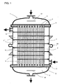
- FIG. 1 shows a preferred embodiment of a reactor 1 according to the invention
- Longitudinal section is, with a bundle of contact tubes 2, which are parallel to each other in the longitudinal direction of the reactor 1 are sealingly secured in tube sheets 3, with hoods 4 at both Ends of the reactor 1, and preferably arranged therein gas manifolds 12.
- deflecting plates 6 are arranged perpendicular to the reactor longitudinal direction, the alternating opposing passage openings 7 on the reactor inner wall set free.
- nozzles or partial annular channels 11th intended for the supply and discharge of the heat exchange medium.
- a compensator 10 on the reactor jacket intended.
- FIG. 2 further preferred embodiment differs from the in Fig. 1 illustrated embodiment by the flow of reaction mixture and heat exchange means (cross dc).
- the contact tubes 2 in the inlet region of the gaseous Reaction mixture filled with an inert material.
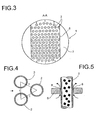
- FIG. 3 illustrates the preferred circular segment-shaped training the released from the baffles 6 passage openings 7 in the area the reactor inner wall.
- Fig. 4 illustrates the preferred arrangement of the contact tubes 2 in a triangular division, the is called in each case the same distance t of the centers of immediately adjacent contact tubes to each other.
- Fig. 5 illustrates the preferred embodiment of columns 8 between Contact tubes 2 and baffles 6.
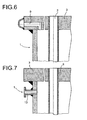
- Fig. 6 shows the preferred arrangement of venting and / or drainage holes 9 in Tube bottom 3 to the outside.
- the mouth of the venting and / or drainage holes after outside is preferred, as shown in Fig. 6, with a welded-on half-shell as Collector covered.
- Fig. 7 illustrates a different type of ventilation, by means of vent pipe 13.
- a hole is drilled in the reactor jacket and a nozzle welded, preferably about 20 mm below the tubesheet.
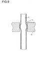
- the reactor shown in longitudinal section in FIG. 8 has a separating plate 14 through which the gap 5 between the contact tubes 2 in a first, upper zone and a second, lower zone is liquid-tightly separated. From the Fig. It can be seen that, in a preferred method, a partial flow emerging from the second zone Heat exchange medium mixed with the heat transfer medium stream supplied to the first zone can be.
- Fig. 9 shows a detail of the reactor shown in Fig. 8, namely the liquid-tight Rolling or hydraulic pipe expansion of the Needlesrobrs 2 in the separating plate 14, whereby the gap 15 between the contact tube 2 and the separating plate 14 is closed.
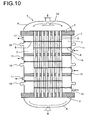
- Fig. 10 shows a further preferred embodiment of a reactor 1 with three through Dividers 14 liquid-tight separated zones.
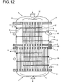
- FIG. 11 shows an arrangement of two reactors connected in series, being on the lower hood of the upper reactor and on the upper hood of the lower reactor was waived. Between the lower tube plate of the upper reactor and the upper tube plate of the lower reactor, a spacer 16 is provided. Both reactors are each untouched in the deflection region for the heat transfer medium.
- Fig. 12 differs from the previous one in that the second reactor is fully bored, that is also in the deflection area for the Heat transfer medium is equipped with contact tubes.
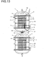
- FIG. 13 shows a device with two reactors 1 connected in series with one another Sleeve 17, which opens via the lower hood 4 of the first reactor 1 to the outside and the inclusion of a multi-thermoelement 18 is used.
- a concentration measuring point 19 for the residual chlorine content and a temperature measuring point 20 is provided in the link between the Both reactors 1 in the link between the Both reactors 1 in the link between the Both reactors 1 in the link between the Both reactors 1 in the link between the Both reactors 1 is a concentration measuring point 19 for the residual chlorine content and a temperature measuring point 20 is provided.
- FIG. 14 clarifies the arrangement of the multi-thermocouple 18 several Temperaturmesspunlcten in the sleeve 17, via the nozzle 22 in the lower Hood 4 of the reactor 1 opens to the outside.
- the detailed representation in FIG. 14 clarifies beyond the support 21 for the catalyst in the catalyst tube. 2
- the contact tubes were made of duplex steel 1.4462.
- the inlet temperature of the reaction mixture was 50 ° C.
- the inlet temperature of the liquid coolant, monochlorobenzene, was 60 ° C.
- the reactor according to the invention in the deflection region for the heat exchange medium, that is in the region of the passage openings of the baffles, tube-free leave.
- the heat transfer coefficient with 200 W / m 2 / K of the coolant to the tube wall was significantly lower compared to the heat transfer coefficient of the cross-flowed contact tubes, with 800 W / m 2 / K.
- the reactor according to the invention was exclusive Contact tubes with transverse flow through the heat transfer medium available, with the above significant procedural advantages compared to the along flowed contact tubes in the deflection region for the heat transfer medium.
- the gas load could be mixed with the reaction mixture at the same time Increase the amount of coolant to about twice compared to a reactor be increased according to the prior art, with the result of a corresponding increase the capacity and extension of the service life of the reactor.
Landscapes
- Chemical & Material Sciences (AREA)
- Organic Chemistry (AREA)
- Chemical Kinetics & Catalysis (AREA)
- Inorganic Chemistry (AREA)
- Physics & Mathematics (AREA)
- Fluid Mechanics (AREA)
- Engineering & Computer Science (AREA)
- Materials Engineering (AREA)
- Organic Low-Molecular-Weight Compounds And Preparation Thereof (AREA)
- Devices And Processes Conducted In The Presence Of Fluids And Solid Particles (AREA)
- Low-Molecular Organic Synthesis Reactions Using Catalysts (AREA)
Abstract
Description
Die Erfindung betrifft ein Verfahren zur Herstellung von Phosgen durch Gasphasenreaktion von Kohlenmonoxid und Chlor in Gegenwart eines Feststoffkatalysators.The invention relates to a process for the preparation of phosgene by gas phase reaction of carbon monoxide and chlorine in the presence of a solid catalyst.
Phosgen wird großtechnisch in einer katalytischen Gasphasenreaktion von Kohlenmonoxid und Chlor in Gegenwart eines Feststoffkatalysators, bevorzugt Aktivkohle hergestellt. Die Reaktion ist stark exotherm, die Bildungsenthalpie beträgt -107,6 kJ/mol. Die Reaktion wird in der Regel in einem Rohrbündelreaktor nach dem in Ullmanns Enzyklopädie der technischen Chemie, Vol. A 19, Seite 413 bis 414 beschriebenen Verfahren, hergestellt. Danach wird der körnige Katalysator, mit einer Korngröße im Bereich von 3 bis 5 mm, in Rohren mit einem Innendurchmesser zwischen 50 und 70 mm eingesetzt. Bei 40 bis 50°C springt die Reaktion an, die Temperatur steigt in den Rohren bis auf etwa 580°C und fällt dann wieder ab. Kohlenmonoxid wird in geringem Überschuss eingesetzt, um zu gewährleisten, dass das gesamte Chlor umgesetzt wird und um chlorfreies Phosgen zu erhalten. Die Reaktion kann drucklos oder unter Druck durchgeführt werden, häufig bei 2 bis 5 bar, um das Phosgen bereits mit Kühlwasser kondensieren zu können.Phosgene is being commercialized in a catalytic gas phase reaction of carbon monoxide and chlorine in the presence of a solid catalyst, preferably activated carbon. The Reaction is highly exothermic, the enthalpy of formation is -107.6 kJ / mol. The reaction is usually in a tube bundle reactor according to the in Ullmanns Encyclopedia of Technical Chemistry, Vol. A 19, pages 413-414. Thereafter, the granular catalyst, with a grain size in the range of 3 to 5 mm, in Tubes with an inner diameter between 50 and 70 mm used. At 40 to 50 ° C If the reaction starts, the temperature rises in the tubes to about 580 ° C and falls then off again. Carbon monoxide is used in slight excess to ensure that all the chlorine is reacted and to obtain chlorine-free phosgene. The reaction can be carried out without pressure or under pressure, frequently at 2 to 5 bar, to be able to condense the phosgene already with cooling water.
Phosgen ist ein wichtiger Hilfsstoff bei der Herstellung von Zwischen- und Endprodukten in nahezu allen Zweigen der Chemie. Das mengenmäBig größte Verwendungsgebiet ist die Herstellung von Diisocyanaten für die Polyurethanchemie, insbesondere von Toluylendiisocyanat und von 4,4-Diisocyanat-diphenylmethan.Phosgene is an important auxiliary in the production of intermediates and end products in almost all branches of chemistry. The quantitatively largest area of application is the Preparation of diisocyanates for polyurethane chemistry, in particular toluene diisocyanate and of 4,4-diisocyanate-diphenylmethane.
Zur besseren Abführung der Reaktionswärme über das zwischen den Kontaktrohren zirkulierende Wärmetauschmittel werden Umlenkbleche zwischen den Kontaktrohren eingebaut, die eine Queranströmung der Kontaktrohre durch das Wärmetauschmittel bewirken.For better dissipation of the heat of reaction over the circulating between the catalyst tubes Heat transfer medium baffles are installed between the catalyst tubes, causing a cross-flow of the catalyst tubes through the heat exchange medium.
Bekannte Rohrbündelreaktoren für die Herstellung von Phosgen sind zwecks maximaler Raumausnutzung im Reaktorinnenraum vollständig berohrt. Sie weisen Umlenkbleche zwischen den Kontaktrohren auf, die relativ kurz gehalten sind, d.h. sie reichen im Umlenkbereich nicht bis zur Reaktorinnenwand, sondern lassen jeweils einen Anteil von etwa 25 bis 30 % des gesamten Reaktorquerschnitts frei, um den Druckabfall des Wärmetauschmittels und somit die Betriebskosten für die Umwälzpumpe des Wärmetauschmittels zu begrenzen. Im Umlenkbereich ändert sich das Strömungsprofil des Wärmetauschmittels um die Kontaktrohre von Queranströmung auf Längsanströmung. Die Kontaktrohre werden schlechter gekühlt, und in der Folge treten an den Kontaktrohren im Umlenkbereich Korrosionsprobleme auf.Known tube bundle reactors for the production of phosgene are for the purpose of maximum Space utilization in the reactor interior completely drilled. They have baffles between the contact tubes, which are kept relatively short, i. they range in the deflection area not to the reactor inner wall, but each leave a share of about 25 to 30% of the total reactor cross-section free to the pressure drop of the heat exchange medium and thus the operating costs for the circulation pump of the heat exchange medium to limit. In the deflection region, the flow profile of the heat exchange medium changes around the contact tubes from transverse flow to longitudinal flow. The contact tubes are worse cooled, and subsequently occur at the contact tubes in the deflection Corrosion problems.
Die US 3,807,963 beschreibt die Verwendung eines Röhrenreaktors zur Dehydrierugn von alkylierten Kohlenwasserstoffen in Gegenwart von Wasserdampf, wobei die alkylierten Kohlenwasserstoffe, speziell Ethylbenzol, gleichzeitig Edukt und Wärmeträger sind. Bei den hohen Temperaturen des beschriebenen Verfahrens, oberhalb von ca. 600 °C, liegt das Wärmetauschmittel gasförmig vor. Bei der Auslegung des Reaktors ist in solchen Fällen insbesondere der Druckabfall des Wärmetauschmittels zu berücksichtigen.US Pat. No. 3,807,963 describes the use of a tubular reactor for dehydrogenating alkylated hydrocarbons in the presence of water vapor, the alkylated Hydrocarbons, especially ethylbenzene, at the same time educt and heat transfer are. at the high temperatures of the described method, above about 600 ° C, is the Heat exchange medium before gas. In the design of the reactor is in such cases in particular to take into account the pressure drop of the heat exchange medium.
Die US 4,231,959 beschreibt ein Verfahren zur Herstellung von Phosgen unter Verwendung von zwei hintereinander geschalteten Reaktoren, wobei der erste Reaktor ein Rohrbündelreaktor ist und der zweite Reaktor ein Rohrbündelreaktor sein kann. Indem die Umsetzung in zwei hintereinander geschalteten Reaktoren durchgeführt wird, kann der Überschuss an Kohlenmonoxid, der erforderlich ist, um die nahezu vollständige Umsetzung des Chlors zu gewährleisten, gegenüber herkömmlichen Verfahren, mit Durchführung in einem einzigen Apparat, reduziert werden.US 4,231,959 describes a process for the preparation of phosgene using of two reactors connected in series, the first reactor being a tube-bundle reactor and the second reactor may be a tube bundle reactor. By the implementation is carried out in two reactors connected in series, the excess to carbon monoxide, which is required to complete the almost complete implementation of To ensure chlorine, compared to conventional methods, with implementation in one single apparatus, to be reduced.
Demgegenüber war es Aufgabe der Erfindung, die Korrosionsprobleme an den Kontaktrohren im Umlenkbereich zu vermeiden und einen Reaktor zur Herstellung von Phosgen zur Verfügung zu stellen, der eine erhöhte spezifische Querschnittsbelastung ermöglicht und somit eine höhere Kapazität aufweist.In contrast, it was an object of the invention, the corrosion problems at the contact tubes to avoid in the deflection and a reactor for the production of phosgene to provide an increased specific cross-sectional load allows and thus has a higher capacity.
Die Lösung geht aus von einem Verfahren zur Herstellung von Phosgen durch Gasphasenreaktion von Kohlenmonoxid und Chlor in Gegenwart eines Feststoffkatalysators, in einem oder mehreren zylinderförmigen Reaktoren mit einem Bündel von parallel zueinander, in Reaktorlängsrichtung angeordneten Kontaktrohren, die an ihren Enden in Rohrböden befestigt sind, mit je einer Haube an beiden Enden des Reaktors, sowie mit senkrecht zur Reaktorlängsrichtung im Zwischenraum zwischen den Kontaktrohren angeordneten Umlenkblechen, die alternierend einander gegenüberliegende Durchtrittsöffnungen an der Reaktorinnenwand freilassen, wobei die Kontaktrohre mit dem Feststoffkatalysator befüllt sind, das gasförmige Reaktionsgemisch von einem Reaktorende über eine Haube durch die Kontaktrohre geleitet und vom entgegengesetzten Reaktorende über die zweite Haube abgezogen und durch den Zwischenraum um die Kontaktrohre ein flüssiges Wärmetauschmittel geleitet wird.The solution is based on a process for the production of phosgene by gas phase reaction of carbon monoxide and chlorine in the presence of a solid catalyst, in one or a plurality of cylindrical reactors with a bundle of parallel to each other, in Reactor longitudinal direction arranged contact tubes attached at their ends in tube sheets are, each with a hood at both ends of the reactor, as well as with perpendicular to the Reactor longitudinal direction in the space between the catalyst tubes arranged baffles, the alternately opposite passage openings at the Release the reactor inner wall, wherein the contact tubes filled with the solid catalyst are the gaseous reaction mixture from a reactor end through a hood through the Conduits passed and withdrawn from the opposite end of the reactor over the second hood and through the space around the catalyst tubes, a liquid heat exchange medium is directed.
Die Erfindung ist dadurch gekennzeichnet, dass der Reaktor (die Reaktoren) im Bereich der Durchtrittsöffnungen unberohrt ist (sind).The invention is characterized in that the reactor (s) in the range the passages are untested (are).
Der Begriff Durchtrittsöffnung bezeichnet vorliegend den Bereich zwischen dem freien Ende eines Umlenkbleches und der Reaktorinnenwand.The term passage opening in the present case denotes the area between the free one End of a baffle and the reactor inner wall.
Es wurde gefunden, dass durch die erfindungsgemäße Freilassung des Reaktorinnenraums im Bereich der Durchtrittsöffnungen die Kapazität eines Reaktors zur Herstellung von Phosgen bei unverändertem Volumen des Innenraums und erhöhter Kühlmittelmenge um den Faktor 1,5 bis 2,0 gegenüber einem vollberohrten Reaktor erhöht werden kann, obwohl eine niedrigere Gesamtzahl von Kontaktrohren im Reaktor untergebracht ist.It has been found that by the release of the reactor interior according to the invention in the region of the passage openings, the capacity of a reactor for the production of Phosgene with unchanged volume of the interior and increased amount of coolant around although the factor 1.5 to 2.0 can be increased over a full bore reactor a lower total number of catalyst tubes is housed in the reactor.
Es wurde darüber hinaus gefunden, dass der Reaktor zur Durchführung des erfindungsgemäßen Verfahrens zur Herstellung von Phosgen durch Gasphasenreaktion von Kohlenmonoxid und Chlor in Gegenwart eines Feststoffkatalysators auch ohne Kompensatoren zum Ausgleich von thermischen Spannungen im Reaktormantel gebaut werden kann: es wurde gefunden, dass die durch die exotherme Reaktion bedingte Temperaturerhöhung der Kontaktrohrwände nur in Teilbereichen derselben auftritt, daher über die Länge der Kontaktrohre weitgehend aufgefangen werden kann und nur noch geringe Spannungen in den Schweißnähten der Kontaktrohreinschweißungen an den Rohrböden bewirkt. Dieser Effekt nimmt mit zunehmender Länge der Kontaktrohre zu, insbesondere ab einer Länge der Kontaktrohre größer als 2,5 m. Indem auf Kompensatoren am Reaktormantel verzichtet wird, wird der Reaktor insgesamt steifer, und daher können die Rohrböden mit geringerer Dicke ausgelegt werden. Dies führt in vorteilhafter Weise zu leichteren Apparaten und darüber hinaus wird bei unveränderter Gesamtlänge des Apparates die für die Unterbringung der Katalysatorfüllung nutzbare Länge der Kontaktrohre größer, mit entsprechender Laufzeitverlängerung des Reaktors. So ist beispielsweise eine Verlängerung der Katalysatorfüllung um etwa 40 cm realisierbar, mit der Folge einer Laufzeitverlängerung des Reaktors in der Größenordnung von einem Jahr. Darüber hinaus wird der Reaktor ohne Kompensator preiswerter. It has also been found that the reactor for carrying out the inventive Process for the preparation of phosgene by gas phase reaction of carbon monoxide and chlorine in the presence of a solid catalyst even without compensators for Compensation of thermal stresses in the reactor jacket can be built: it was found that caused by the exothermic reaction increase in temperature of the contact tube walls occurs only in partial areas thereof, therefore over the length of the contact tubes can be largely absorbed and only low voltages in the Welds the Kontaktrohreinschweißungen effected on the tube sheets. This effect increases with increasing length of the contact tubes, in particular from a length of Contact tubes larger than 2.5 m. By dispensing with compensators on the reactor jacket As a result, the reactor as a whole becomes stiffer, and therefore the tubesheets may become less dense Thickness to be designed. This leads advantageously to lighter apparatus and In addition, with unchanged overall length of the apparatus for accommodation the catalyst filling usable length of the contact tubes larger, with appropriate Runtime extension of the reactor. For example, an extension of the catalyst filling can be realized by about 40 cm, with the result of a runtime extension of the reactor on the order of one year. In addition, the reactor is without compensator cheaper.
Der Reaktor ist bezüglich seiner Geometrie grundsätzlich nicht eingeschränkt. Bevorzugt ist er zylinderförmig ausgebildet, möglich sind jedoch auch Formen mit beispielsweise quadratischem oder rechteckigem Querschnitt.The reactor is basically not limited in terms of its geometry. Prefers he is cylindrical, but also possible forms with, for example square or rectangular cross-section.
Im Reaktor ist ein Bündel, das heißt eine Vielzahl von Kontaktrohren parallel zueinander in Reaktorlängsrichtung angeordnet. Die Anzahl der Kontaktrohre liegt bevorzugt im Bereich von 100 bis 10000, insbesondere von 1000 bis 3500.In the reactor is a bundle, that is, a plurality of catalyst tubes parallel to each other arranged in the reactor longitudinal direction. The number of contact tubes is preferably in the range from 100 to 10,000, especially from 1000 to 3500.
Die Kontaktrohre sind aus einem korrosionsfesten Material, beispielsweise Edelstahl, bevorzugt Duplexstahl 1.4462, Edelstahl 1.4571 oder Edelstahl 1.4541 gebildet. Bevorzugt ist der gesamte Reaktor aus den vorerwähnten Werkstoffen, insbesondere aus Duplex- oder Edelstahl gebildet.The contact tubes are made of a corrosion-resistant material, such as stainless steel, preferred Duplex steel 1.4462, stainless steel 1.4571 or stainless steel 1.4541 formed. Prefers is the entire reactor of the aforementioned materials, in particular of duplex or Made of stainless steel.
Jedes Kontaktrohr weist bevorzugt eine Wandstärke im Bereich von 2,0 bis 4,0 mm, insbesondere von 2,5 bis 3,0 mm, und einen Rohrinnendurchmesser im Bereich von 20 bis 90 mm, bevorzugt im Bereich von 30 bis 35 mm auf.Each contact tube preferably has a wall thickness in the range of 2.0 to 4.0 mm, in particular from 2.5 to 3.0 mm, and a tube inside diameter in the range of 20 to 90 mm, preferably in the range of 30 to 35 mm.
Die Kontaktrohre weisen bevorzugt eine Länge im Bereich von 1,5 bis 6,0 m, insbesondere im Bereich von 2,0 bis 3,5 m, auf.The contact tubes preferably have a length in the range of 1.5 to 6.0 m, in particular in the range of 2.0 to 3.5 m, on.
Die Kontaktrohre sind bevorzugt derart im Reaktorinnenraum angeordnet, dass das Verhältnis zwischen dem Abstand der Mittelpunkte unmittelbar benachbarter Kontaktrohre und dem Außendurchmesser der Kontaktrohre im Bereich von 1,15 bis 1,4, bevorzugt im Bereich von 1,2 bis 1,3 liegt und dass die Kontaktrohre in Dreiecksteilung im Reaktor angeordnet sind.The contact tubes are preferably arranged in such a way in the reactor interior that the ratio between the distance of the centers of immediately adjacent contact tubes and the outer diameter of the catalyst tubes in the range of 1.15 to 1.4, preferably in Range of 1.2 to 1.3 and that the contact tubes arranged in a triangular division in the reactor are.
Die Kontaktrohre sind an beiden Enden in Rohrböden flüssigkeitsdicht befestigt, bevorzugt verschweißt. Die Rohrböden bestehen ebenfalls aus einem korrosionsfesten Material, bevorzugt Edelstahl, insbesondere Duplexstahl, besonders bevorzugt aus dem selben Material wie die Kontaktrohre.The contact tubes are attached liquid-tightly at both ends in tube sheets, preferably welded. The tube sheets are also made of a corrosion-resistant material, preferably Stainless steel, in particular duplex steel, particularly preferably from the same material like the contact tubes.
Der Innendurchmesser des Reaktors beträgt, sofern es sich um einen zylinderförmigen Apparat handelt, 0,5 bis 6,0 m, bevorzugt 1,0 bis 3,0 m.The internal diameter of the reactor, if it is a cylindrical apparatus is 0.5 to 6.0 m, preferably 1.0 to 3.0 m.
Beide Reaktorenden sind nach außen durch Hauben begrenzt. Durch eine Haube erfolgt die Zuführung des Reaktionsgemisches zu den Kontaktrohren, durch die Haube am anderen Ende des Reaktors wird der Produktstrom abgezogen. Both reactor ends are limited to the outside by hoods. Through a hood, the Supply of the reaction mixture to the contact tubes, through the hood at the other At the end of the reactor, the product stream is withdrawn.
In den Hauben sind bevorzugt Gasverteiler zur Vergleichmäßigung des Gasstromes angeordnet, beispielsweise in Form einer Platte, insbesondere einer perforierten Platte.Gas distributors are preferably arranged in the hoods to equalize the gas flow. for example in the form of a plate, in particular a perforated plate.
Im Zwischenraum zwischen den Kontaktrohren sind senkrecht zur Reaktorlängsrichtung Umlenkbleche angeordnet, die alternierend einander gegenüberliegende Durchtrittsöffnungen an der Reaktorinnenwand freilassen. Die Umlenkbleche bewirken eine Umlenkung des im Reaktorinnenraum, im Zwischenraum zwischen den Kontaktrohren zirkulierenden Wärmetauschmittels, dergestalt, dass die Kontaktrohre vom Wärmetauschmittel quer angeströmt werden, wodurch die Wärmeabführung verbessert wird. Um diese vorteilhafte Queranströmung der Kontaktrohre zu erreichen, müssen die Umlenkbleche alternierend an die einander gegenüberliegenden Seiten der Reaktorinnenwand Durchtrittsöffnungen für das Wärmetauschmittel freilassen.In the space between the catalyst tubes are perpendicular to the reactor longitudinal direction Arranged deflecting plates, the alternately opposite passage openings on the inside wall of the reactor. The baffles cause a deflection of the in the reactor interior, circulating in the space between the catalyst tubes Heat exchange means, such that the contact tubes of the heat exchange medium flows transversely be, whereby the heat dissipation is improved. To this advantageous To achieve cross-flow of the catalyst tubes, the baffles must alternately the opposite sides of the reactor inner wall passages for release the heat transfer medium.
Die Anzahl der Umlenkbleche beträgt bevorzugt etwa 6 bis 21. Vorzugsweise sind sie äquidistant zu einander angeordnet, besonders bevorzugt ist jedoch die unterste und die oberste Umlenkscheibe jeweils vom Rohrboden weiter entfernt als der Abstand zweier aufeinanderfolgende Umlenkscheiben zueinander, bevorzugt um etwa das 1,5-fache.The number of baffles is preferably about 6 to 21. Preferably, they are equidistant arranged to each other, but particularly preferred is the lowest and the upper deflecting disc each further away from the tube plate than the distance between two successive deflecting disks to each other, preferably by about 1.5 times.
Die Form der freigelassenen Durchtrittsöffnungen ist grundsätzlich beliebig. Für den Fall eines zylindrischen Reaktors sind sie bevorzugt kreissegmentförmig.The shape of the released passage openings is basically arbitrary. In the case of a cylindrical reactor, they are preferably circular segment-shaped.
Bevorzugt lassen alle Umlenkbleche jeweils gleiche Durchtrittsöffnungen frei.Preferably, all baffles release the same passage openings.
Die Fläche jeder Durchtrittsöffnung beträgt bevorzugt 5 bis 20 %, insbesondere 8 bis 14 % des Reaktorquerschnitts.The area of each passage opening is preferably 5 to 20%, in particular 8 to 14%. of the reactor cross-section.
Bevorzugt sind die Umlenkbleche nicht dichtend um die Kontaktrohre angeordnet, und lassen eine Leckageströmung von bis zu 40 Vol.-% des Gesamtstroms des Wärmetauschmittels zu. Hierzu sind zwischen den Kontaktrohren und Umlenkblechen Spalte im Bereich von 0,1 bis 0,6 mm, bevorzugt von 0,2 bis 0,3 mm vorgesehen.Preferably, the baffles are not arranged sealingly around the catalyst tubes, and allow a leakage flow of up to 40% by volume of the total flow of the heat exchange medium to. For this purpose, gaps are in the range between the contact tubes and baffles from 0.1 to 0.6 mm, preferably from 0.2 to 0.3 mm provided.
Es ist vorteilhaft, die Umlenkbleche mit Ausnahme der Bereiche der Durchtrittsöffnungen zur Reaktorinnenwand hin flüssigkeitsdicht zu gestalten, so dass dort kein zusätzlicher Leckagestrom auftritt.It is advantageous, the baffles except the areas of the openings to make liquid-tight to the reactor inner wall, so there is no additional Leakage current occurs.
Die Umlenkbleche werden aus einem korrosionsfesten Material, bevorzugt Edelstahl, insbesondere Duplexstahl, bevorzugt in einer Dicke von 8 bis 30 mm, bevorzugt von 10 bis 20 mm, gebildet.The baffles are made of a corrosion-resistant material, preferably stainless steel, in particular Duplex steel, preferably in a thickness of 8 to 30 mm, preferably from 10 to 20 mm, formed.
Die Kontaktrohre sind mit einem Feststoffkatalysator, bevorzugt Aktivkohle, gefüllt. Die Katalysatorschüttung in den Kontaktrohren weist bevorzugt ein Lückenvolumen von 0,33 bis 0,5, insbesondere von 0,33 bis 0,40, auf.The catalyst tubes are filled with a solid catalyst, preferably activated carbon. The Catalyst bed in the catalyst tubes preferably has a void volume of 0.33 to 0.5, in particular from 0.33 to 0.40, on.
Bevorzugt sind in beiden Rohrböden Entlüftungs- und/oder Ablaufbohrungen vorgesehen, insbesondere an mehreren, bevorzugt an 2 bis 4, symmetrisch über den Reaktorquerschnitt verteilten Stellen, deren Öffnungen nach außen bevorzugt in auf der Reaktoraußenwand aufgeschweißten Halbschalen münden.Venting and / or drain holes are preferably provided in both tube plates, in particular at several, preferably at 2 to 4, symmetrically over the reactor cross-section distributed sites, whose openings are preferred to the outside in on the reactor outer wall open welded half shells.
Zum Ausgleich von thermischen Ausdehnungen ist im Reaktormantel vorteilhaft ein Kompensator vorgesehen. To compensate for thermal expansions, a compensator is advantageous in the reactor jacket intended.
Die Zu- und Abführung des Wärmetauschmittels in bzw. aus dem Zwischenraum zwischen den Kontaktrohren erfolgt bevorzugt über Stutzen oder Teilringkanäle am Reaktormantel, die Öffnungen zum Reaktorinnenraum aufweisen, bevorzugt mit kreisförmigem oder rechteckigem Querschnitt und mit einem Öffnungsverhältnis im Bereich von 5 bis 50 %, bevorzugt von 15 bis 30 %.The supply and discharge of the heat exchange medium into and out of the space between the catalyst tubes preferably take place via connecting pieces or partial ring channels on the reactor jacket, have the openings to the reactor interior, preferably with circular or rectangular cross-section and with an aperture ratio in the range of 5 to 50%, preferably from 15 to 30%.
Es ist bevorzugt, den Reaktor in Bezug auf eine Querschnittsebene in der Reaktormitte symmetrisch auszubilden. Gemäß dieser bevorzugten Ausführungsform weist somit ein aufrechtstehender Reaktor jeweils einen identischen unteren und oberen Teil auf. Darunter wird auch verstanden, dass alle Anschlüsse sowie die Reaktorpratzen, die der Reaktorabstützung dienen, symmetrisch ausgebildet sind. Der Katalysator wird, je nach Reaktionsfortschritt, als Folge der Wanderung der Hot-Spot-Zone unterschiedlich verbraucht. Analog werden die Kontaktrohre in unterschiedlichen Bereichen verschieden beansprucht, mit stärkster Beanspruchung im Bereich der Hot-Spot-Zone. In dieser Hot-Spot-Zone kommt es zuerst zum Abtrag der Innenwand der Kontaktrohre und zur Gefahr, dass die Kontaktrohre undicht werden. Bei Undichte muss der gesamte Reaktor von Katalysatorfüllung und Wärmetauschmittel entleert und die entleerte Katalysatorfüllung mehrere Tage lang mit Stickstoff gespült werden. Das oder die undichten Rohre müssen ausgewechselt und neu mit Katalysator befüllt werden. Dieser Gefahr kann durch die oben beschriebene symmetrische Ausführungsform vorgebeugt werden, bei der es möglich ist, den Reaktor rechtzeitig vor dem Erreichen eines bestimmten kritischen Abtrages zu drehen, wobei dann der Hot-Spot-Bereich auf einen zuvor weniger beanspruchten Teil der Kontaktrohre trifft. Dadurch lässt sich die Betriebszeit des Reaktors beträchtlich steigern, häufig verdoppeln.It is preferred to have the reactor in relation to a cross-sectional plane in the reactor center symmetrical form. Thus, according to this preferred embodiment upright reactor each have an identical lower and upper part. among them is also understood that all connections and the reactor claws, the reactor support serve, are formed symmetrically. The catalyst becomes, depending on reaction progress, consumed differently as a result of the migration of the hot spot zone. Analogous the contact tubes are claimed differently in different areas, with most severe stress in the area of the hot spot zone. In this hot spot zone comes it first for removal of the inner wall of the contact tubes and the risk that the contact tubes be leaking. In leaks, the entire reactor of catalyst filling and Heat exchange medium emptied and the emptied catalyst filling with several days Be purged with nitrogen. The or the leaking pipes must be replaced and new be filled with catalyst. This danger can be due to the symmetrical Be prevented embodiment in which it is possible to timely the reactor before reaching a certain critical deviation, in which case the hot spot area encounters a previously less stressed part of the contact tubes. Thereby the operating time of the reactor can be increased considerably, often doubling.
In einer vorteilhaften Ausführungsform ist der Reaktor mehrzonig, insbesondere zwei- oder dreizonig, mit unterschiedlicher Temperierung der Zonen, ausgebildet. Besonders bevorzugt ist die Ausbildung als Zweizonen-Reaktor. Diese Ausführungsform kann besonders vorteilhaft eingesetzt werden, wenn für die Reaktion zu Phosgen von weitgehend von Brom befreitem Chlor ausgegangen wird. Dabei wurde beobachtet, dass die Bildungsreaktion des Phosgens langsamer verläuft, als beim Einsatz von mit Brom verunreinigtem Chlor. Ursache hierfür könnte eine Radikalbildung von Brom mit Aktivkohle sein, die die Reaktion mit Chlor beschleunigt. Verläuft die Bildungsreaktion von Phosgen langsamer, beispielsweise wegen des Einsatzes von weitgehend von Brom gereinigtem Chlor, so wäre es grundsätzlich möglich, durch Anhebung der Wärmetauschmitteleintrittstemperatur den Gesamtumsatz zu Phosgen zu erhöhen. Dies ist jedoch nur begrenzt möglich, da das flüssige Wärmetauschmittel an der Außenwand der Kontaktrohre sieden kann und somit kein eindeutiger Wärmeübergang und keine eindeutige Reaktionsführung gewährleistet ist.In an advantageous embodiment, the reactor is multi-zone, in particular two- or three-zoned, with different temperature of the zones formed. Especially preferred is the training as a two-zone reactor. This embodiment may be particularly be used to advantage when largely for the reaction of phosgene of Bromine liberated chlorine is assumed. It was observed that the formation reaction of phosgene is slower than when using bromine contaminated Chlorine. This could be due to a radical formation of bromine with activated carbon, which is the Reaction accelerated with chlorine. Is the formation reaction of phosgene slower, for example, because of the use of largely chlorine-purified chlorine, so would it is basically possible by raising the heat transfer medium inlet temperature the To increase total sales to phosgene. However, this is only possible to a limited extent because the liquid Boil heat transfer medium on the outer wall of the catalyst tubes can and therefore no clear heat transfer and no clear reaction is guaranteed.
Daher wird eine vorteilhafte Ausführungsform als Zweizonen-Reaktor zur Verfügung gestellt, mit unterschiedlicher Temperierung der beiden Zonen und zwar mit einer stärkeren Kühlung in der ersten Zone in Strömungsrichtung des Reaktionsgemisches, dem Hauptreaktionsbereich und mit einer schwächeren Kühlung in der zweiten Zone, im Nachreaktionsbereich bzw. im Bereich, in dem der Restumsatz erfolgt. In der ersten Zone wird vorzugsweise mit kälterem Wärmetauschmittel temperiert gegenüber der zweiten Zone.Therefore, an advantageous embodiment is provided as a two-zone reactor, with different temperature of the two zones and with a stronger Cooling in the first zone in the flow direction of the reaction mixture, the main reaction region and with a weaker cooling in the second zone, in the post-reaction zone or in the area in which the remaining sales take place. In the first zone is preferably tempered with colder heat exchange medium with respect to the second zone.
Die beiden Zonen sind im Zwischenraum zwischen den Kontaktrohren durch ein Trennblech voneinander flüssigkeitsdicht getrennt, dergestalt, dass das Wärmetauschmittel innerhalb des Reaktors nicht aus einer Zone in die andere strömen kann. Die Kontaktrohre sind in den Trennblechen dichtend eingewalzt oder hydraulisch aufgeweitet. Das Trennblech wird vorteilhaft mit einer Dicke im Bereich von 15 bis 60 mm, bevorzugt von 30 bis 50 mm ausgebildet.The two zones are in the space between the contact tubes by a separating plate separated from each other liquid-tight, such that the heat exchange medium within of the reactor can not flow from one zone to the other. The contact tubes are rolled sealingly in the dividing plates or widened hydraulically. The separating plate is advantageous with a thickness in the range of 15 to 60 mm, preferably from 30 to 50 mm formed.
Für die Ausbildung von Drei- oder Mehrzonen-Reaktoren sind entsprechend zwei oder mehrere Trennbleche zur Abtrennung der einzelnen Zonen voneinander vorzusehen.For the formation of three- or multi-zone reactors are accordingly two or provide several dividers for separating the individual zones from each other.
Zum Ausgleich von thermischen Spannungen ist vorteilhaft in jeder Reaktionszone am Reaktormantel jeweils ein Kompensator vorzusehen.To compensate for thermal stresses is advantageous in each reaction zone on Reactor casing each provide a compensator.
Die Aufteilung von Zone 1 zu Zone 2 kann, für den Fall des Zweizonen-Reaktors, in einem
Verhältnis im Bereich von 1 : 1 bis 3 : 1, vorteilhaft im Verhältnis 2 : 1 erfolgen.The division from
Die Gesamtlänge der Kontaktrohre eines Zweizonen-Reaktors liegt häufig im Bereich zwischen 2,5 und 6,0 m, bevorzugt im Bereich zwischen 3,0 und 4,0 m.The total length of the contact tubes of a two-zone reactor is often in the range between 2.5 and 6.0 m, preferably in the range between 3.0 and 4.0 m.
Der Reaktionsfortschritt lässt sich an der Austrittstemperatur des Wärmetauschmittels aus der zweiten Zone erkennen. Steigt die Temperatur dort merklich an, ist dies ein Zeichen, dass die Reaktionsfront in den unteren Bereich des Reaktors wandert.The reaction progress is at the outlet temperature of the heat exchange medium recognize the second zone. If the temperature rises noticeably there, this is a sign that the reaction front migrates into the lower region of the reactor.
Für die zweite Zone ist ein geringerer Volumenstrom an Wärmetauschmittel gegenüber der ersten Zone erforderlich. Der aus der zweiten Zone austretende Wärmetauschmittelstrom kann mit dem in die erste Zone eintretenden Wärmetauschmittelstrom zusammengeführt werden, so dass durch die erste Zone ein größerer Gesamtstrom an Wärmetauschmittel fließt.For the second zone is a lower volume flow of heat exchange medium over the first zone required. The emerging from the second zone heat transfer medium flow can be combined with the entering into the first zone heat exchange medium flow be so that through the first zone a larger total flow of heat exchange medium flows.
Die Umlenkbereiche für das Wärmetauschmittel sind vorzugsweise in allen Zonen des Zwei-, Drei- oder Mehrzonen-Reaktors unberohrt.The deflection areas for the heat exchange medium are preferably in all zones of the Two-, three- or multi-zone reactor untouched.
Bevorzugt ist in mindestens einem der Kontaktrohre eine Hülse zur Aufnahme eines Multi-Thermoelementes mit zwei oder mehreren Temperaturmesspunkten angeordnet, die unterhalb des Reaktors mündet. Die Hülse wird über einen Stutzen durch die untere Haube des Reaktors geführt. Die Anordnung im unteren Kontaktrohrbereich ist aufgrund der niedrigeren Reaktionstemperatur in diesem Bereich vorteilhaft. In der Regel ist die Temperatur im oberen Kontaktrohrbereich eines Phosgenreaktors höher, mit entsprechend stärkerer Belastung der Werkstoffe durch das aggressive, Phosgen und Chlor umfassende Reaktionsgemisch. Wird die Hülse dagegen, wie vorgeschlagen, im unteren Kontaktrohrbereich angeordnet, so ist die Belastung für den Werkstoff der Hülse, aufgrund der dort niedrigeren Temperaturen, geringer. Das Multi-Thermoelement ist bevorzugt fest verdrahtet und weist zwei oder mehrere, bevorzugt bis zu 10, vorzugsweise regelmäßig beabstandete Temperaturmesspunkte auf. Durch die Temperaturmessung kann der Reaktionsfortschritt überwacht werden und Messwerte gewonnen werden, die Rückschlüsse auf die Katalysatoraktivität und den geeigneten Zeitpunkt zum Auswechseln desselben erlauben.Preferably, in at least one of the contact tubes, a sleeve for receiving a multi-thermocouple arranged with two or more temperature measuring points below of the reactor opens. The sleeve is connected via a connecting piece through the lower hood of the Run reactor. The arrangement in the lower contact tube area is due to the lower Reaction temperature in this area advantageous. In general, the temperature is in upper contact tube area of a phosgene reactor higher, with correspondingly heavier load the materials by the aggressive, phosgene and chlorine comprehensive reaction mixture. If, on the other hand, the sleeve is arranged in the lower contact tube region, as proposed, so is the load on the material of the sleeve, due to the lower there Temperatures, lower. The multi-thermocouple is preferably hard-wired and has two or more, preferably up to 10, preferably regularly spaced temperature measuring points on. By measuring the temperature, the reaction progress can be monitored and measured values are obtained, the conclusions on the catalyst activity and allow the appropriate time for replacement.
Das erfindungsgemäße Verfahren kann auch in einer Vorrichtung zur Herstellung von Phosgen durch Gasphasenreaktion von Kohlenmonoxid und Chlor in Gegenwart eines Feststofflcatalysators durchgeführt werden, gebildet aus zwei oder mehreren wie vorstehend beschriebenen Reaktoren, die hintereinander geschaltet sind und wobei bevorzugt im Verbindungsteil zwischen der unteren Haube des oberen Reaktors und der oberen Haube des unteren Reaktors eine Konzentrationsmessstelle für den Restchlor-Gehalt und/oder eine Temperaturmessstelle vorgesehen ist.The inventive method can also be used in a device for the production of Phosgene by gas phase reaction of carbon monoxide and chlorine in the presence of a Solid catalyst can be carried out, formed from two or more as above described reactors which are connected in series and wherein preferably in Connecting part between the lower hood of the upper reactor and the upper hood the lower reactor, a concentration measuring point for the residual chlorine content and / or a temperature measuring point is provided.
Vorzugsweise sind zwei Reaktoren hintereinander geschaltet und der zweite Reaktor weist Kontaktrohre mit größerem Rohrinnendurchmesser gegenüber dem ersten Reaktor auf, insbesondere mit einem Rohrinnendurchmesser im Bereich von 20 bis 110 mm, vorzugsweise im Bereich von 60 bis 90 mm.Preferably, two reactors are connected in series and the second reactor has Contact tubes with a larger inner tube diameter compared to the first reactor, in particular with a tube inside diameter in the range of 20 to 110 mm, preferably in the range of 60 to 90 mm.
In einer weiteren Ausführungsform ist es möglich, zwei oder mehrere Reaktoren unmittelbar hintereinander zu schalten, unter Verzicht auf dazwischen angeordnete Hauben. Bevorzugt werden zwei Reaktoren unmittelbar hintereinander geschaltet. Die aneinander angrenzenden Rohrböden, das heißt der untere Rohrboden des ersten Reaktors und der obere Rohrboden des zweiten Reaktors sind vorteilhaft mittels Distanzhaltern beabstandet miteinander verbunden, um eine Quervermischung des aus den Kontaktrohren des ersten Reaktors austretenden Reaktionsgemisches vor Eintritt desselben in den zweiten Reaktor zu ermöglichen.In another embodiment, it is possible to have two or more reactors directly to switch in succession, waiving interposed hoods. Prefers two reactors are connected directly in series. The adjoining ones Tube bottoms, that is, the lower tube plate of the first reactor and the upper Tube bottom of the second reactor are advantageously spaced apart by spacers connected to a cross-mixing of the from the contact tubes of the first reactor exiting reaction mixture before entering the same in the second reactor enable.
Vorteilhaft kann ein wie vorstehend beschriebener Reaktor oder eine Vorrichtung von einer Sicherheitskammer umschlossen sein. Dabei ist es bevorzugt, den zweiten und/oder die weiteren Reaktoren gegenüber dem davor angeordneten Reaktor mit kleinerem Außenmaß auszubilden, wodurch dieselben leichter ausgetauscht werden können.Advantageously, a reactor as described above or a device of a Enclosed security chamber. It is preferred that the second and / or the other reactors with respect to the previously arranged reactor with a smaller external dimension which makes them easier to replace.
Gegenstand der Erfindung ist auch ein Verfahren zur Herstellung von Phosgen durch Gasphasenreaktion von Kohlenmonoxid und Chlor in Gegenwart eines Feststoffkatalysators in einem wie vorstehend beschriebenen Reaktor.The invention also provides a process for the preparation of phosgene by gas phase reaction of carbon monoxide and chlorine in the presence of a solid catalyst in a reactor as described above.
Im erfindungsgemäßen Verfahren wird bevorzugt als flüssiges Wärmetauschmittel Wasser, wässrige Natriumhydroxidlösung, oder ein oder mehrere, bevorzugt chlorierte, Kohlenwasserstoffe, insbesondere Monochlorbenzol, eingesetzt.In the process according to the invention, water is preferably used as the liquid heat exchange medium. aqueous sodium hydroxide solution, or one or more, preferably chlorinated, hydrocarbons, especially monochlorobenzene used.
Das erfindungsgemäße Verfahren ist bezüglich der Stromführung von gasförmigem Reaktionsgemisch und Wärmetauschmittel nicht eingeschränkt; es ist gleichermaßen möglich, das gasförmige Reaktionsgemisch und das flüssige Wärmetauschmittel im Kreuzgegenstrom oder im Kreuzgleichstrom durch den Reaktor zu führen. Hierbei kann das gasförmige Reaktionsgemisch gleichermaßen von oben wie auch von unten über die Hauben durch die Kontaktrohre des Reaktors geleitet werden.The inventive method is with respect to the flow of gaseous reaction mixture and heat transfer medium not restricted; it's equally possible the gaseous reaction mixture and the liquid heat exchange medium in cross-countercurrent or cross-flow through the reactor. Here, the gaseous Reaction mixture equally from above as well as from below over the hoods through the contact tubes of the reactor are passed.
Der in die Kontaktrohre eingebrachte Katalysator ist bevorzugt Aktivkohle, insbesondere in Form von Kugeln, Kegeln, Zylindern, Stränglingen, Ringen oder Tabletten. Besonders bevorzugt ist der der Zuführung des gasförmigen Reaktionsgemisches zugewandte Bereich der Kontaktrohre auf eine Länge von 5 bis 20 %, bevorzugt auf eine Länge von 3 bis 10 %, der Gesamtrohrlänge der Kontaktrohre mit einem Inertmaterial befüllt.The introduced into the catalyst tubes catalyst is preferably activated carbon, in particular in the form of spheres, cones, cylinders, stringers, rings or tablets. Especially preferred is the supply of the gaseous reaction mixture facing area the contact tubes to a length of 5 to 20%, preferably to a length of 3 to 10%, the total tube length of the contact tubes filled with an inert material.
Bevorzugt kann in die Kontaktrohre ein zumindest teilweise offenporiger Kohlenstoffschaum als Katalysator eingebracht werden. Derartige Katalysatoren sind besonders vorteilhaft aufgrund der sehr großen inneren Oberfläche. An at least partially open-pore carbon foam may preferably be introduced into the catalyst tubes be introduced as a catalyst. Such catalysts are particularly advantageous due to the very large inner surface.
Die Kontaktrohre werden bevorzugt, insbesondere durch ihre Anordnung im Reaktorinnenraum, dergestalt ausgelegt, dass ihr wärmetauschmittelseitiger Wärmeübergangskoeffizient im Bereich von 500 bis 2000 W/m2/K, insbesondere im Bereich von 1000 bis 1500 W/m2/K, liegt.The contact tubes are preferably designed, in particular by their arrangement in the reactor interior, such that their heat exchange medium side heat transfer coefficient is in the range of 500 to 2000 W / m 2 / K, in particular in the range of 1000 to 1500 W / m 2 / K.
Das erfindungsgemäße Verfahren wird bevorzugt in der Weise durchgeführt, dass man Kohlenmonoxid und Chlor in einem Molverhältnis im Bereich von 1,01 bis 1,10, insbesondere in einem Bereich von 1,03 bis 1,06 von oben oder von unten durch die Kontaktrohre leitet, wobei die Längsachse des Reaktors vertikal ausgerichtet ist.The inventive method is preferably carried out in such a way that one Carbon monoxide and chlorine in a molar ratio in the range of 1.01 to 1.10, in particular in a range of 1.03 to 1.06 from above or below through the contact tubes conducts, wherein the longitudinal axis of the reactor is vertically aligned.
Im erfindungsgemäßen Verfahren beträgt der Druck im Reaktor bevorzugt 2 bis 10 bar absolut, insbesondere 3 bis 5 bar absolut.In the process according to the invention, the pressure in the reactor is preferably 2 to 10 bar absolute, in particular 3 to 5 bar absolute.
Die Querschnittsbelastung des Reaktors beträgt bevorzugt 0,5 bis 4 kg Phosgen pro sec. und pro m2 angeströmte Reaktionsrohrquerschnittsfläche, insbesondere 1,5 bis 3 kg Phosgen pro sec. und m2 angeströmte Reaktionsrohrquerschnittsfläche. Die Querschnittsbelastung ist somit gegenüber herkömmlichen Phosgenreaktoren erhöht.The cross-sectional loading of the reactor is preferably 0.5 to 4 kg of phosgene per second and per m 2 of flown reaction tube cross-sectional area, in particular 1.5 to 3 kg of phosgene per second and m 2 flown reaction tube cross-sectional area. The cross-sectional load is thus increased compared to conventional phosgene reactors.
Die Erfindung wird im Folgenden anhand einer Zeichnung sowie von Ausführungsbeispielen näher erläutert.The invention will be described below with reference to a drawing and embodiments explained in more detail.
Es zeigen im Einzelnen:
Figur 1- eine erste bevorzugte Ausführungsform eines erfindungsgemäßen Reaktors im Längsschnitt mit Kreuzgegenstromführung von Reaktionsgemisch und Wärmetauschmittel,
Figur 2- eine weitere bevorzugte Ausführungsform eines erfindungsgemäßen Reaktors im Längsschnitt, wobei Reaktionsgemisch und Wärmetauschmittel im Kreuzgleichstrom geführt werden und die Kontaktrohre im Eintrittsbereich des Reaktionsgemisches mit einem Inertmaterial befüllt sind,
Figur 3- einen Querschnitt in der Ebene A-A durch einen in Fig. 1 oder Fig. 2 dargestellten erfindungsgemäßen Reaktor,
Figur 4- einen Teilbereich des Querschnitts aus Fig. 3,
- Fig. 5
bis 7 - jeweils Teilbereiche der Längsschnittdarstellungen in Fig. 1 oder Fig. 2,
- Fig. 8
- eine bevorzugte Ausführungsform eines Zweizonen-Realctors,
- Fig. 9
- eine Detaildarstellung des Reaktors aus Fig. 8,
- Fig. 10
- eine bevorzugte Ausführungsform eines Dreizonen-Reaktors,
- Fig. 11
- eine bevorzugte Ausführungsform von zwei unmittelbar übereinander angeordneten Reaktoren, wobei beide Reaktoren im Umlenkbereich des Wärmetauschmittels unberohrt sind,
- Fig. 12
- eine weitere bevorzugte Ausführungsform von zwei unmittelbar übereinander angeordneten Reaktoren, wobei der zweite Reaktor voll berohrt ist,
Figur 13- eine Vorrichtung mit zwei hintereinander geschalteten Reaktoren und
Figur 14- einen Ausschnitt aus Figur 13 mit einer Hülse zur Aufnahme eines Thermoelementes.
- FIG. 1
- a first preferred embodiment of a reactor according to the invention in longitudinal section with cross-countercurrent flow of reaction mixture and heat transfer medium,
- FIG. 2
- a further preferred embodiment of a reactor according to the invention in longitudinal section, wherein reaction mixture and heat exchange medium are conducted in the cross-direct current and the catalyst tubes are filled in the inlet region of the reaction mixture with an inert material,
- FIG. 3
- a cross section in the plane AA through a reactor according to the invention shown in Fig. 1 or Fig. 2,
- FIG. 4
- a portion of the cross section of Fig. 3,
- Fig. 5 to 7
- respective subregions of the longitudinal sectional representations in FIG. 1 or FIG. 2,
- Fig. 8
- a preferred embodiment of a two-zone realctor,
- Fig. 9
- a detailed view of the reactor of Fig. 8,
- Fig. 10
- a preferred embodiment of a three-zone reactor,
- Fig. 11
- a preferred embodiment of two reactors arranged directly one above the other, both reactors being unthreaded in the deflection region of the heat exchange medium,
- Fig. 12
- a further preferred embodiment of two reactors arranged directly above one another, wherein the second reactor is fully bored,
- FIG. 13
- a device with two reactors connected in series and
- FIG. 14
- a detail of Figure 13 with a sleeve for receiving a thermocouple.
In den Figuren bezeichnen gleiche Bezugsziffern gleiche oder entsprechende Merkmale.In the figures, like reference numerals designate like or corresponding features.
Figur 1 stellt eine bevorzugte Ausführungsform eines erfindungsgemäßen Reaktors 1 im
Längsschnitt dar, mit einem Bündel von Kontaktrohren 2, die parallel zueinander in Längsrichtung
des Reaktors 1 in Rohrböden 3 abdichtend befestigt sind, mit Hauben 4 an beiden
Enden des Reaktors 1, und mit bevorzugt darin angeordneten Gasverteilern 12. Im Zwischenraum
5 zwischen den Kontaktrohren 2, der vom flüssigen Wärmetauschmittel durchströmt
wird, sind Umlenkbleche 6 senkrecht zur Reaktorlängsrichtung angeordnet, die alternierend
einander gegenüberliegende Durchtrittsöffnungen 7 an der Reaktorinnenwand
freilassen.FIG. 1 shows a preferred embodiment of a
Für die Zu- und Abführung des Wärmetauschmittels sind Stutzen oder Teilringkanäle 11 vorgesehen. Zum Ausgleich von thermischen Spannungen ist ein Kompensator 10 am Reaktormantel vorgesehen. For the supply and discharge of the heat exchange medium are nozzles or partial annular channels 11th intended. To compensate for thermal stresses is a compensator 10 on the reactor jacket intended.
Die in Fig. 2 dargestellte weitere bevorzugte Ausführungsform unterscheidet sich von der in Fig. 1 dargestellten Ausführungsform durch die Stromführung von Reaktionsgemisch und Wärmetauschmittel (Kreuzgleichstrom).The illustrated in Fig. 2 further preferred embodiment differs from the in Fig. 1 illustrated embodiment by the flow of reaction mixture and heat exchange means (cross dc).
Bevorzugt sind, wie in Fig. 2 dargestellt, die Kontaktrohre 2 im Eintrittsbereich des gasförmigen
Reaktionsgemisches mit einem Inertmaterial befüllt.Preferably, as shown in Fig. 2, the
Die Querschnittsdarstellung in Fig. 3 verdeutlicht die bevorzugt kreissegmentförmige Ausbildung
der von den Umlenkblechen 6 freigelassenen Durchtrittsöffnungen 7 im Bereich
der Reaktorinnenwand.The cross-sectional view in Fig. 3 illustrates the preferred circular segment-shaped training
the released from the
Fig. 4 verdeutlicht die bevorzugte Anordnung der Kontaktrohre 2 in Dreiecksteilung, das
heißt mit jeweils gleichem Abstand t der Mittelpunkte unmittelbar benachbarter Kontaktrohre
zueinander.Fig. 4 illustrates the preferred arrangement of the
Der Ausschnitt in Fig. 5 verdeutlicht die bevorzugte Ausbildung von Spalten 8 zwischen
Kontaktrohren 2 und Umlenkblechen 6.The detail in Fig. 5 illustrates the preferred embodiment of
Fig. 6 zeigt die bevorzugte Anordnung von Entlüftungs- und/oder Ablaufbohrungen 9 im
Rohrboden 3 nach außen. Die Mündung der Entlüftungs- und/oder Ablaufbohrungen nach
außen ist bevorzugt, wie in Fig. 6 dargestellt, mit einer aufgeschweißten Halbschale als
Sammler bedeckt.Fig. 6 shows the preferred arrangement of venting and / or
Der Ausschnitt in Fig. 7 verdeutlicht eine andere Art der Entlüftung, mittels Entlüftungsstutzen
13. Dazu wird in dem Reaktormantel ein Loch gebohrt und ein Stutzen angeschweißt,
bevorzugt ca. 20 mm unterhalb des Rohrbodens.The detail in Fig. 7 illustrates a different type of ventilation, by means of
Der in Fig. 8 im Längsschnitt dargestellte Reaktor weist ein Trennblech 14 auf, durch das
der Zwischenraum 5 zwischen den Kontaktrohren 2 in eine erste, obere Zone und eine
zweite, untere Zone flüssigkeitsdicht getrennt wird. Aus der Fig. ist zu erkennen, dass, in
einer bevorzugten Verfahrensführung, ein Teilstrom des aus der zweiten Zone austretenden
Wärmetauschmittels dem der ersten Zone zugeführten Wärmetauschmittelstrom zugemischt
werden kann. The reactor shown in longitudinal section in FIG. 8 has a separating
Fig. 9 zeigt ein Detail des in Fig. 8 dargestellten Reaktors, und zwar die flüssigkeitsdichte
Einwalzung oder hydraulische Rohraufweitung des Kontaktrobrs 2 in das Trennblech 14,
wodurch der Spalt 15 zwischen Kontaktrohr 2 und Trennblech 14 verschlossen wird.Fig. 9 shows a detail of the reactor shown in Fig. 8, namely the liquid-tight
Rolling or hydraulic pipe expansion of the
Fig. 10 zeigt eine weitere bevorzugte Ausführungsform eines Reaktors 1 mit drei durch
Trennbleche 14 flüssigkeitsdicht voneinander getrennten Zonen.Fig. 10 shows a further preferred embodiment of a
Fig. 11 zeigt eine Anordnung von zwei unmittelbar hintereinandergeschalteten Reaktoren,
wobei auf die untere Haube des oberen Reaktors und auf die obere Haube des unteren Reaktors
verzichtet wurde. Zwischen dem unteren Rohrboden des oberen Reaktors und dem
oberen Rohrboden des unteren Reaktors ist ein Distanzhalter 16 vorgesehen. Beide Reaktoren
sind jeweils im Umlenkbereich für das Wärmetauschmittel unberohrt.11 shows an arrangement of two reactors connected in series,
being on the lower hood of the upper reactor and on the upper hood of the lower reactor
was waived. Between the lower tube plate of the upper reactor and the
upper tube plate of the lower reactor, a
Die in Fig. 12 dargestellte Ausführungsform unterscheidet sich von der vorhergehenden dadurch, dass der zweite Reaktor voll berohrt ist, das heißt auch im Umlenkbereich für das Wärmetauschmittel mit Kontaktrohren ausgestattet ist.The embodiment shown in Fig. 12 differs from the previous one in that the second reactor is fully bored, that is also in the deflection area for the Heat transfer medium is equipped with contact tubes.
Figur 13 zeigt eine Vorrichtung mit zwei hintereinander geschalteten Reaktoren 1 mit einer
Hülse 17, die über die untere Haube 4 des ersten Reaktors 1 nach außen mündet und die
der Aufnahme eines Multi-Thermoelementes 18 dient. Im Verbindungsteil zwischen den
beiden Reaktoren 1 ist eine Konzentrationsmessstelle 19 für den Rest-Chlorgehalt sowie
eine Temperaturmessstelle 20 vorgesehen.FIG. 13 shows a device with two
Der Ausschnitt in Figur 14 verdeutlicht die Anordnung des Multi-Thermoelementes 18 mit
mehreren Temperaturmesspunlcten in der Hülse 17, die über den Stutzen 22 in der unteren
Haube 4 des Reaktors 1 nach außen mündet. Die Detaildarstellung in Figur 14 verdeutlicht
darüber hinaus die Auflage 21 für den Katalysator im Kontaktrohr 2.The detail in FIG. 14 clarifies the arrangement of the multi-thermocouple 18
several Temperaturmesspunlcten in the
Die Erfindung wird im Folgenden anhand eines Ausführungsbeispiels näher erläutert:The invention is explained in more detail below with reference to an exemplary embodiment:
Durch die Kontaktrohre eines zylindrischen Rohrbündelreaktors mit 1256 Kontaktrohren, mit jeweils einer Rohrlänge von 3000 mm, einem Rohrinnendurchmesser von 39,3 mm und einer Wandstärke von 2,6 mm, die im Bereich der Zuführung des Reaktionsgemisches auf einer Länge von 200 mm mit einem inerten keramischen Material und anschließend auf eine Länge von 2700 mm mit einer Schüttung aus einem zylindrischen Katalysator aus Aktivkohle mit dem Durchmesser der zylindrischen Katalysatorteilchen von 4 mm und einer Länge von 5 mm und einer Porosität von 0,404 befüllt waren, wurde ein Chlor-Massenstrom von 7087 kg/h und ein Kohlenmonoxid-Massenstrom von 2913 kg/h bei einem Vordruck des Reaktionsgases, das heißt einem Druck des Reaktionsgases vor dem Reaktor von 4 bar absolut unter Erhalt eines Produktstroms von ca. 10000 kg/h Phosgen durchgeleitet.Through the contact tubes of a cylindrical shell-and-tube reactor with 1256 contact tubes, each with a tube length of 3000 mm, a tube inner diameter of 39.3 mm and a wall thickness of 2.6 mm, in the region of the feed of the reaction mixture on a length of 200 mm with an inert ceramic material and then on a length of 2700 mm with a bed of a cylindrical catalyst Activated carbon with the diameter of the cylindrical catalyst particles of 4 mm and a length of 5 mm and a porosity of 0.404, became a chlorine mass flow of 7087 kg / h and a carbon monoxide mass flow of 2913 kg / h at a Form pressure of the reaction gas, that is, a pressure of the reaction gas before the Reactor of 4 bar absolute to give a product stream of about 10000 kg / h of phosgene passed through.
Im Reaktor waren zehn Umlenkbleche eingebaut, die alternierend im Bereich zwischen dem freien Ende jedes Umlenkbleches und der Reaktorinnenwand kreissegmentförmige Durchtrittsöffnungen freiließen, von jeweils etwa 15 % des gesamten Reaktorquerschnitts.In the reactor ten baffles were installed, alternately in the range between the free end of each baffle and the reactor inner wall circular segment-shaped Open passages, each about 15% of the total reactor cross section.
Die Kontaktrohre waren aus Duplexstahl 1.4462 gebildet.The contact tubes were made of duplex steel 1.4462.
Durch die Kontaktrohre wurde ein Reaktionsgemisch aus Kohlenmonoxid und Chlor in einem Mol-Verhältnis von 1,04226 von oben nach unten durchgeleitet. Das flüssige Kühlmittel, Monochlorbenzol, wurde im Bereich zwischen den Kontaktrohren von unten nach oben durch den Reaktor geleitet.Through the catalyst tubes, a reaction mixture of carbon monoxide and chlorine in passed through a molar ratio of 1.04226 from top to bottom. The liquid coolant, Monochlorobenzene, was in the area between the contact tubes from below to passed through the top of the reactor.
Die Eintrittstemperatur des Reaktionsgemisches betrug 50°C. Die Eintrittstemperatur des flüssigen Kühlmittels, Monochlorbenzol, betrug 60°C.The inlet temperature of the reaction mixture was 50 ° C. The inlet temperature of the liquid coolant, monochlorobenzene, was 60 ° C.
Die oben aufgeführten apparativen und verfahrenstechnischen Bedingungen wurden für einen Vergleichsversuch nach dem Stand der Technik sowie ftir einen Versuch nach dem erfindungsgemäßen Verfahren unverändert belassen. Der einzige Unterschied bestand darin, dass der Reaktor nach dem Stand der Technik im Bereich der Durchtrittsöffnungen für das Wärmetauschmittel vollständig berohrt war, das heißt eine Anzahl von ca. 200 Rohren befanden sich im Bereich der Durchtrittsöffnungen der Umlenkbleche.The apparatus and process conditions listed above were for a comparison experiment according to the prior art as well as for an experiment after the process according to the invention left unchanged. The only difference was in that the reactor according to the prior art in the region of the passage openings for the heat exchange medium was completely drilled, that is, a number of about 200 Pipes were in the area of the passage openings of the baffles.
Demgegenüber wurde der erfindungsgemäße Reaktor im Umlenkbereich für das Wärmetauschmittel, das heißt im Bereich der Durchtrittsöffnungen der Umlenkbleche, rohrfrei belassen.In contrast, the reactor according to the invention in the deflection region for the heat exchange medium, that is in the region of the passage openings of the baffles, tube-free leave.
Für den Reaktor nach dem Stand der Technik wurden die in der nachfolgenden Tabelle
aufgeführten signifikanten Unterschiede zwischen Kontaktrohren im Umlenkbereich für
das Wärmetauschmittel und vom Wärmetauschmittel quer angeströmten Kontaktrohren,
das heißt Kontaktrohren außerhalb des Umlenkbereichs für das Wärmetauschmittel aufgezeigt:

Für die Kontaktrohre im Umlenkbereich war der Wärmeübergangskoeffizient mit 200 W/m2/K des Kühlmittels zur Rohrwand signifikant niedriger gegenüber dem Wärmeübergangskoeffizienten der quereingeströmten Kontaktrohre, mit 800 W/m2/K.For the contact tubes in the deflection region, the heat transfer coefficient with 200 W / m 2 / K of the coolant to the tube wall was significantly lower compared to the heat transfer coefficient of the cross-flowed contact tubes, with 800 W / m 2 / K.
Dieses Ergebnis erklärt sich dadurch, dass im Reaktor nach dem Stand der Technik in den vollberohrten Umlenkbereichen an der Reaktorinnenwand überwiegend eine Längsströmung des Wärmetauschmittels, jedoch kaum Querströmung auftrat. Demgemäss stieg die Temperatur der Rohre auf den das Material schädigenden Wert von 295,9°C. Das Wärmetauschmittel fing sogar an, lokal zu sieden. Durch größere Gasblasen wurde die Kühlung noch schlechter. Durch Zersetzung des Wärmetauschmittels bildeten sich Ablagerungen auf der Außenseite der Kontaktrohre, die isolierend wirkten.This result is explained by the fact that in the reactor according to the prior art in the vollberohren deflection areas on the reactor inner wall predominantly a longitudinal flow of the heat exchange medium, but hardly any cross flow occurred. Accordingly, the Temperature of the pipes to the material damaging value of 295.9 ° C. The heat transfer medium even started to boil locally. By larger gas bubbles was the cooling even worse. Decomposition of the heat exchange medium formed deposits on the outside of the contact tubes, which had an insulating effect.
Entsprechend wurde in einem Langzeitversuch mit einem Reaktor nach dem Stand der Technik ein starker Materialabtrag, von etwa 0,8 mm pro Jahr, an den Kontaktrohren im Umlenkbereich sowie teilweise Verkokungen des Wärmetauschmittels Monochlorbenzol auf der Kühlmittelseite der Kontaktrohre gefunden.Accordingly, in a long-term experiment with a state-of-the-art reactor Technology a heavy material removal, of about 0.8 mm per year, at the contact tubes in the Deflection area and partial coking of the heat exchange medium monochlorobenzene found on the coolant side of the catalyst tubes.
Demgegenüber war in den Bereichen mit Queranströmung der Wärmeübergangskoeffizient des Wärmetauschmittels zur Rohrwand auf den vierfachen Wert erhöht. In der Folge wurden für die Wandtemperatur auf der Innenseite der Kontaktrohre für das Rohrmaterial unschädliche 151,8°C erreicht, die bei den Druckverhältnissen im Wärmetauschmittel um die Kontaktrohre, von 2,5 bar absolut, noch unterhalb der Siedetemperatur des Wärmetauschmittels Monochlorbenzol liegen. Im Ergebnis wurde auch keine Schädigung der Kontaktrohre im Querstrombereich gefunden. In contrast, in the cross-flow areas, the heat transfer coefficient was of the heat exchange medium to the tube wall increased to four times. In the episode were for the wall temperature on the inside of the contact tubes for the pipe material harmless 151.8 ° C, the at the pressure ratios in the heat exchange medium to the Contact tubes, from 2.5 bar absolute, still below the boiling point of the heat transfer medium Monochlorobenzene lie. As a result, there was no damage to the catalyst tubes found in the crossflow area.
Darüber hinaus war auch der maximale Anstieg der mittleren Reaktionstemperatur in der Katalysatorschüttung in quer angeströmten Kontaktrohren mit 545,5° gegenüber 568,5°C in den Kontaktrohren im Umlenkbereich deutlich niedriger.In addition, the maximum increase in the average reaction temperature was also in the Catalyst bed in cross-flowed contact tubes with 545.5 ° to 568.5 ° C. in the contact tubes in the deflection significantly lower.
Im erfindungsgemäßen Reaktor wurde demgegenüber auf die Kontaktrohre im Bereich der Durchtrittsöffnungen der Umlenkbleche, das heißt im Umlenkbereich für das Wärmetauschmittel, verzichtet. Dadurch waren im erfindungsgemäßen Reaktor ausschließlich Kontaktrohre mit Queranströmung durch das Wärmetauschmittel vorhanden, mit den oben dargelegten signifikanten verfahrenstechnischen Vorteilen gegenüber den überwiegend längs angeströmten Kontaktrohren im Umlenkbereich für das Wärmetauschmittel.In contrast, in the reactor according to the invention on the contact tubes in the Through openings of the baffles, that is in the deflection region for the heat transfer medium, waived. As a result, the reactor according to the invention was exclusive Contact tubes with transverse flow through the heat transfer medium available, with the above significant procedural advantages compared to the along flowed contact tubes in the deflection region for the heat transfer medium.
Durch die erfindungsgemäße Verfahrensführung konnten beachtliche Wirtschaftlichkeitssteigerungen erreicht werden: ausgehend vom gleichen Reaktor, der jedoch gegenüber dem Stand der Technik in den Umlenkbereichen für das Wärmetauschmittel, wie im Beispiel dargestellt, unberohrt war, konnte die Gasbelastung mit dem Reaktionsgemisch bei gleichzeitiger Erhöhung der Kühlmittelmenge auf etwa das Doppelte gegenüber einem Reaktor nach dem Stand der Technik erhöht werden, mit der Folge einer entsprechenden Erhöhung der Kapazität und Verlängerung der Standzeit des Reaktors.By the process control according to the invention could be considerable increases in efficiency be achieved: starting from the same reactor, but compared to the State of the art in the deflection areas for the heat exchange medium, as in the example Untreated, the gas load could be mixed with the reaction mixture at the same time Increase the amount of coolant to about twice compared to a reactor be increased according to the prior art, with the result of a corresponding increase the capacity and extension of the service life of the reactor.
Claims (17)
- A process for preparing phosgene by gas-phase reaction of carbon monoxide and chlorine in the presence of a solid catalyst in one or more cylindrical reactors (1) which has/have a bundle of parallel catalyst tubes (2) which are aligned in the longitudinal direction of the reactor and whose ends are fixed in tube plates (3), with a cap (4) at each end of the reactor (1) and deflection plates (6) which are aligned perpendicular to the longitudinal direction of the reactor in the intermediate space (5) between the catalyst tubes (2) and leave free passages (7) located alternately opposite one another on the interior wall of the reactor, with the catalyst tubes (2) being charged with the solid catalyst, the gaseous reaction mixture being passed from one end of the reactor via one cap (4) through the catalyst tubes (2) and being taken off from the opposite end of the reactor (1) via the second cap (4) and a liquid heat transfer medium being passed through the intermediate space (5) around the catalyst tubes (2), wherein the reactor (the reactors) (1) for carrying out the process has/have no tubes in the region of the passages (7) .
- A process as claimed in claim 1, wherein the deflection plates (6) are configured as segments of a circle, all deflection plates (6) each leave equal-sized passages (7) free and the area of each passage (7) is from 5 to 20%, preferably from 8 to 14%, of the cross section of the reactor.
- A process as claimed in claim 1 or 2, wherein from 100 to 10 000, preferably from 1000 to 3500, catalyst tubes (2) are present and each catalyst tube (2) has a length in the range from 1.5 to 6.0 m, preferably in the range from 2.0 to 3.5 m, and a wall thickness in the range from 2.0 to 4.0 mm, in particular from 2.5 to 3.0 mm, and an internal diameter in the range from 20 to 90 mm, preferably in the range from 30 to 55 mm.
- A process as claimed in any of claims 1 to 3, wherein gaps (8) of from 0.1 to 0.6 mm, preferably from 0.2 to 0.3 mm, are present between the catalyst tubes (2) and the deflection plates (6) are fixed in a liquid-tight manner to the interior wall of the reactor with the exception of the regions of the passages (7).
- A process as claimed in any of claims 1 to 4, wherein the deflection plates have a thickness in the range from 8 to 30 mm, preferably from 10 to 20 mm.
- A process as claimed in any of claims 1 to 5, wherein vent and/or discharge holes (9) are provided in the tube plates (3), a compensator (10) is provided in the reactor wall and ports or part-ring channels (11) are provided on the reactor wall for the introduction and discharge of the heat transfer medium and the openings of these ports or part-ring channels (11) to the interior of the reactor preferably have a circular or rectangular cross section and an opening ratio in the range from 5 to 50%.
- A process as claimed in any of claims 1 to 6, wherein the reactor (reactors) is (are) constructed symmetrically about a cross-sectional plane in the middle of the reactor.
- A process as claimed in any of claims 1 to 7, wherein the reactor (the reactors) (1) has (have) a plurality of zones, in particular two or three zones, with the individual zones being separated from one another in a liquid-tight manner by dividing plates (14) so that the heat transfer medium cannot flow from one zone into the other within the reactor (the reactors) (1).
- A process as claimed in any of claims 1 to 8, wherein a sheath (17) for accommodating a multithermocouple (19) with two or more temperature measuring points, which opens out below the reactor (1), is provided in at least one of the catalyst tubes (2).
- A process as claimed in any of claims 1 to 9 which is carried out in two or more reactors (1) connected in series, with a concentration measuring point (19) for the residual chlorine content and/or a temperature measuring point (20) preferably being provided in the connecting piece between the lower cap of the upper reactor and the upper cap of the lower reactor.
- A process as claimed in claim 10 which is carried out in reactors (1) connected in series, wherein the second reactor has catalyst tubes (2) having a greater internal tube diameter compared to the first reactor (1), in particular an internal tube diameter in the range from 20 to 110 mm, preferably in the range from 60 to 90 mm, the reactors (1) are connected directly in series without caps (4) located in between and spacers (16) are provided between the reactors (1).
- A process as claimed in any of claims 1 to 11, wherein the reactor (the reactors) (1) is (are) enclosed by a safety chamber.
- A process as claimed in any of claims 10 to 12, wherein the second and/or further reactors (1) has/have a smaller external dimension than the upstream reactor (1).
- A process as claimed in any of claims 1 to 13, wherein water, aqueous sodium hydroxide solution or one or more, preferably chlorinated hydrocarbons, in particular monochlorobenzene, is used as heat transfer medium and the gaseous reaction mixture and the liquid heat transfer medium are passed through the reactor (1) in cross-countercurrent or in cross-cocurrent.
- A process as claimed in any of claims 1 to 14, wherein carbon monoxide and chlorine are passed in a molar ratio in the range from 1.01 to 1.10, preferably in the range from 1.03 to 1.06, from above or from below through the catalyst tubes (2) and the longitudinal axis of the reactor (1) is vertical.
- A process as claimed in any of claims 1 to 15, wherein the solid catalyst installed in the catalyst tubes (2) is activated carbon or an at least partially open-pored carbon foam, preferably in the form of spheres, cones, cylinders, extrudates, rings or pellets, and the region of the catalyst tubes (2) at the end at which the gaseous reaction mixture is fed in is preferably filled with an inert material to a length of from 5 to 20%, preferably a length of from 3 to 10%, of the total length of the catalyst tubes (2).
- A process as set forth in any of claims 1 to 16, wherein the catalyst tubes (2) have a heat transfer coefficient on the heat transfer medium side in the range from 500 to 2000 W/m2/K, preferably in the range from 1000 to 1500 W/m2/K.
Applications Claiming Priority (3)
| Application Number | Priority Date | Filing Date | Title |
|---|---|---|---|
| DE10208398 | 2002-02-27 | ||
| DE10208398 | 2002-02-27 | ||
| PCT/EP2003/001372 WO2003072237A1 (en) | 2002-02-27 | 2003-02-12 | Reactor and method for producing phosgene |
Publications (2)
| Publication Number | Publication Date |
|---|---|
| EP1485195A1 EP1485195A1 (en) | 2004-12-15 |
| EP1485195B1 true EP1485195B1 (en) | 2005-11-16 |
Family
ID=27762465
Family Applications (1)
| Application Number | Title | Priority Date | Filing Date |
|---|---|---|---|
| EP03706482A Expired - Lifetime EP1485195B1 (en) | 2002-02-27 | 2003-02-12 | Method for producing phosgene |
Country Status (12)
| Country | Link |
|---|---|
| US (2) | US8409539B2 (en) |
| EP (1) | EP1485195B1 (en) |
| JP (1) | JP4424991B2 (en) |
| KR (1) | KR100936420B1 (en) |
| CN (1) | CN1302842C (en) |
| AT (1) | ATE309856T1 (en) |
| AU (1) | AU2003208834A1 (en) |
| BR (1) | BR0307973A (en) |
| DE (1) | DE50301676D1 (en) |
| ES (1) | ES2253661T3 (en) |
| IN (1) | IN237581B (en) |
| WO (1) | WO2003072237A1 (en) |
Cited By (1)
| Publication number | Priority date | Publication date | Assignee | Title |
|---|---|---|---|---|
| WO2014009346A1 (en) | 2012-07-11 | 2014-01-16 | Bayer Materialscience Ag | Device and method for producing phosgene |
Families Citing this family (73)
| Publication number | Priority date | Publication date | Assignee | Title |
|---|---|---|---|---|
| KR100936420B1 (en) * | 2002-02-27 | 2010-01-12 | 바스프 에스이 | Reactor and method for producing phosgene |
| JP4145607B2 (en) * | 2002-08-23 | 2008-09-03 | 三菱化学株式会社 | Vapor phase catalytic oxidation method using multitubular reactor |
| DE102004010383B4 (en) * | 2004-03-03 | 2007-04-12 | Man Dwe Gmbh | Apparatus for simulating the reaction process in and method of optimizing tubular jacketed reactors |
| DE102004018267B4 (en) * | 2004-04-15 | 2007-05-03 | Man Dwe Gmbh | Reactor arrangement for carrying out catalytic gas phase reactions |
| DE102004041777A1 (en) | 2004-08-28 | 2006-03-02 | Bayer Materialscience Ag | Process and apparatus for the production of phosgene |
| DE102005001952A1 (en) * | 2005-01-14 | 2006-07-27 | Man Dwe Gmbh | Tube bundle reactor for carrying out exothermic or endothermic gas phase reactions |
| DE102005032663A1 (en) | 2005-07-13 | 2007-01-18 | Bayer Materialscience Ag | Process for the preparation of isocyanates |
| DE102005061626A1 (en) * | 2005-12-21 | 2007-06-28 | Basf Ag | Continuous heterogeneous catalyzed partial dehydrogenation of hydrocarbon involves feeding hydrocarbon to reaction chamber enclosed by shell made of specific steel, passing hydrocarbon through catalyst bed and dehydrogenating feed |
| JP4692351B2 (en) * | 2006-03-29 | 2011-06-01 | Jfeスチール株式会社 | Argon purifier attached to air separator |
| US7504533B2 (en) * | 2006-04-24 | 2009-03-17 | Bayer Materialscience Llc | Process for the production of isocyanates |
| DE102006022761A1 (en) * | 2006-05-16 | 2007-11-22 | Bayer Materialscience Ag | Process for the preparation of isocyanates |
| DE102006023261A1 (en) | 2006-05-18 | 2007-11-22 | Bayer Materialscience Ag | Process for the production of chlorine from hydrogen chloride and oxygen |
| DE102006023581A1 (en) * | 2006-05-19 | 2007-11-22 | Bayer Materialscience Ag | Process for separating chlorine from the product gas of an HCl oxidation process |
| DE102006024518A1 (en) * | 2006-05-23 | 2007-11-29 | Bayer Materialscience Ag | Process for the production of chlorine from hydrogen chloride and oxygen |
| DE102006024506A1 (en) * | 2006-05-23 | 2007-11-29 | Bayer Materialscience Ag | Process for the production of chlorine from hydrogen chloride and oxygen |
| DE102006024515A1 (en) * | 2006-05-23 | 2007-11-29 | Bayer Materialscience Ag | Procedure for carrying out an optionally catalyst-supported hydrogen chloride oxidation process, comprises: cooling a process gas; separating non-reacted hydrogen chloride, drying product gases and separating chlorine from the mixture |
| DE102006024516A1 (en) * | 2006-05-23 | 2007-11-29 | Bayer Materialscience Ag | Process for the production of chlorine from hydrogen chloride and oxygen |
| DE102006029790A1 (en) * | 2006-06-27 | 2008-01-03 | Basf Ag | Continuous heterogeneously catalyzed partial dehydrogenation of hydrocarbon involves dehydrogenation through catalyst bed disposed in reaction chamber and with generation of product gas |
| CN101020891B (en) * | 2007-02-07 | 2011-04-06 | 秦皇岛领先科技发展有限公司 | Shell-and-tube fixed bioreactor |
| DE102007020444A1 (en) | 2007-04-27 | 2008-11-06 | Bayer Materialscience Ag | Process for the oxidation of a hydrogen chloride-containing gas mixture |
| WO2009116977A2 (en) * | 2007-12-18 | 2009-09-24 | Dow Technology Investments Llc | Tube reactor |
| DE102007061477A1 (en) * | 2007-12-20 | 2009-07-02 | Man Dwe Gmbh | Tube reactor |
| DE102008009761A1 (en) * | 2008-02-19 | 2009-08-27 | Bayer Materialscience Ag | Process for the preparation of isocyanates |
| DE102008012037A1 (en) | 2008-03-01 | 2009-09-03 | Bayer Materialscience Ag | Process for the preparation of methylene diphenyl diisocyanates |
| EP2370400B2 (en) * | 2008-11-26 | 2019-10-16 | Huntsman International LLC | Process for manufacturing isocyanates |
| JP5336828B2 (en) * | 2008-12-02 | 2013-11-06 | 三井化学株式会社 | Carbonyl chloride production method and production apparatus, and polyisocyanate production method and production apparatus |
| PT2379216T (en) | 2008-12-16 | 2018-01-10 | Basf Se | Reactor and process for the production of phosgene |
| HUE047744T2 (en) * | 2008-12-16 | 2020-05-28 | Basf Se | Reactor and method for producing phosgene |
| CN102348639A (en) * | 2009-03-11 | 2012-02-08 | 巴斯夫欧洲公司 | Method for producing phosgene |
| DE102009032020A1 (en) | 2009-07-07 | 2011-01-13 | Bayer Materialscience Ag | Process for the production of polycarbonate |
| SG174714A1 (en) | 2010-03-30 | 2011-10-28 | Bayer Materialscience Ag | Process for preparing diaryl carbonates and polycarbonates |
| US9175135B2 (en) | 2010-03-30 | 2015-11-03 | Bayer Materialscience Ag | Process for preparing diaryl carbonates and polycarbonates |
| CN101893251B (en) * | 2010-07-26 | 2011-09-21 | 王兴军 | Heat absorber of boiler |
| FR2965490B1 (en) | 2010-09-30 | 2013-01-11 | Aet Group | DEVICE AND METHOD FOR CONTINUOUS PHOSGENATION |
| EP2586767A1 (en) | 2011-10-25 | 2013-05-01 | Bayer MaterialScience AG | Method for manufacturing diaryl carbonates and polycarbonates |
| JP6156860B2 (en) * | 2012-04-04 | 2017-07-05 | 住友化学株式会社 | Multi-tube reactor and design method of multi-tube reactor |
| KR101361002B1 (en) * | 2012-05-21 | 2014-02-12 | 고등기술연구원연구조합 | Indirect heating type volatile organic compounds reactor |
| WO2015013644A1 (en) | 2013-07-26 | 2015-01-29 | Sabic Innovative Plastics Ip B.V. | Method and apparatus for producing high purity phosgene |
| KR102078126B1 (en) | 2013-07-26 | 2020-02-17 | 사빅 글로벌 테크놀러지스 비.브이. | Method and apparatus for producing high purity phosgene |
| JP5667253B2 (en) * | 2013-08-01 | 2015-02-12 | 三井化学株式会社 | Carbonyl chloride production equipment and polyisocyanate production equipment |
| CN104415770B (en) * | 2013-08-26 | 2016-08-31 | 万华化学集团股份有限公司 | A kind of catalyst preparing phosgene and the method preparing phosgene |
| US10106406B2 (en) * | 2013-11-06 | 2018-10-23 | Watt Fuel Cell Corp. | Chemical reactor with manifold for management of a flow of gaseous reaction medium thereto |
| US9358526B2 (en) | 2013-11-19 | 2016-06-07 | Emerging Fuels Technology, Inc. | Optimized fischer-tropsch catalyst |
| US9180436B1 (en) | 2013-11-19 | 2015-11-10 | Emerging Fuels Technology, Inc. | Optimized fischer-tropsch catalyst |
| KR101859209B1 (en) * | 2014-02-04 | 2018-06-27 | 사빅 글로벌 테크놀러지스 비.브이. | Method for producing carbonates |
| JP6316446B2 (en) * | 2014-02-04 | 2018-04-25 | サビック グローバル テクノロジーズ ベスローテン フェンノートシャップ | Method for producing carbonate |
| DE102014202593A1 (en) | 2014-02-13 | 2015-08-13 | Siemens Aktiengesellschaft | Transformation of metal carbonate into metal chloride |
| DE102014202591A1 (en) * | 2014-02-13 | 2015-08-13 | Siemens Aktiengesellschaft | Transformation of metal carbonate into metal chloride |
| EP2955158B1 (en) | 2014-06-11 | 2020-05-27 | Haldor Topsøe A/S | A process for safe production of phosgene |
| CN104190328B (en) * | 2014-08-12 | 2017-02-01 | 中国天辰工程有限公司 | Reactor used for preparing gas-phase hydrogen cyanide |
| DK3194065T3 (en) | 2014-08-20 | 2020-03-16 | Bayer Ag | PROCEDURE FOR PHOS GENERATION OF COMPOUNDS CONTAINING HYDROXYL, THIOL, AMINO AND / OR FORMAMIDE GROUPS |
| CA2993958A1 (en) * | 2015-07-29 | 2017-02-02 | Primus Green Energy Inc. | Two-stage reactor for exothermal and reversible reactions and methods thereof |
| DE102015013516B4 (en) * | 2015-10-20 | 2018-01-18 | Frank Brucker | Shell-and-tube heat exchanger and manufacturing process for shell-and-tube heat exchangers |
| DE102016100908A1 (en) * | 2015-11-06 | 2017-05-11 | L'Air Liquide, Société Anonyme pour l'Etude et l'Exploitation des Procédés Georges Claude | Plant and process for the production of fatty alcohol |
| US11401220B2 (en) | 2016-02-26 | 2022-08-02 | Shell Usa, Inc. | Alkane oxidative dehydrogenation (ODH) |
| CN109476563B (en) * | 2016-07-26 | 2021-09-03 | 国际壳牌研究有限公司 | Oxidative dehydrogenation of ethane (ODH) |
| MX2019000807A (en) * | 2016-07-26 | 2019-10-07 | Shell Int Research | Oxidative dehydrogenation (odh) of ethane. |
| EP3421426A1 (en) * | 2017-06-29 | 2019-01-02 | Covestro Deutschland AG | Energy-efficient process for providing phosgene steam |
| CN107175056A (en) * | 2017-07-12 | 2017-09-19 | 陕西省石油化工研究设计院 | Efficient liquid-core optical fibre photo catalysis reactor |
| EP3498752A1 (en) | 2017-12-18 | 2019-06-19 | Covestro Deutschland AG | Method for producing a polycarbonate using an organic solvent based on hydrochlorocarbon |
| CN109941965B (en) * | 2019-04-21 | 2023-05-26 | 苏州市泰利登净化设备有限公司 | Methanol hydrogen production equipment |
| US20220212936A1 (en) * | 2019-04-25 | 2022-07-07 | Basf Se | Method for producing phosgene |
| CN113891855A (en) * | 2019-05-20 | 2022-01-04 | 巴斯夫欧洲公司 | Method and reactor for producing phosgene |
| KR20220045150A (en) | 2019-08-08 | 2022-04-12 | 코베스트로 인텔렉쳐 프로퍼티 게엠베하 운트 콤파니 카게 | How to prepare polycarbonate |
| CN112441585B (en) * | 2019-08-30 | 2022-07-12 | 万华化学集团股份有限公司 | Phosgene synthesis and brine evaporation and electrolysis integrated treatment process |
| EP3862317A1 (en) | 2020-02-06 | 2021-08-11 | Basf Se | Method and reactor for producing phosgene |
| KR20230012601A (en) | 2020-05-20 | 2023-01-26 | 바스프 에스이 | Methods, reaction mixtures and catalysts for the production of phosgene |
| US20240173684A1 (en) | 2021-03-19 | 2024-05-30 | Basf Se | Apparatus and method for hotspot detection in a tube bundle reactor |
| CN117177940A (en) | 2021-04-21 | 2023-12-05 | 巴斯夫欧洲公司 | Process for the preparation of phosgene |
| US20240269634A1 (en) | 2021-05-27 | 2024-08-15 | Basf Se | Method for producing phosgene |
| CN117693488A (en) | 2021-07-23 | 2024-03-12 | 巴斯夫欧洲公司 | Method for producing phosgene |
| WO2024003247A1 (en) | 2022-06-30 | 2024-01-04 | Basf Se | Process for producing phosgene |
| CN115520868B (en) * | 2022-10-25 | 2023-11-21 | 摩珈(上海)生物科技有限公司 | Phosgene circulating preparation method and device system thereof |
Family Cites Families (11)
| Publication number | Priority date | Publication date | Assignee | Title |
|---|---|---|---|---|
| US2986454A (en) * | 1957-07-23 | 1961-05-30 | American Cyanamid Co | Tubular catalytic converter |
| US3518284A (en) * | 1967-02-20 | 1970-06-30 | Shell Oil Co | Partial oxidation of organic compounds |
| US3807963A (en) * | 1972-03-09 | 1974-04-30 | J Smith | Reaction apparatus |
| DE2238851B2 (en) | 1972-08-07 | 1979-08-30 | Hoechst Ag, 6000 Frankfurt | Process for the production of acrolein and / or acrylic acid while avoiding secondary reactions in the catalytic oxidation of propylene and / or acrolein |
| US4231959A (en) * | 1978-02-15 | 1980-11-04 | Stauffer Chemical Company | Phosgene manufacture |
| CN1073967C (en) * | 1996-02-21 | 2001-10-31 | 纳幕尔杜邦公司 | Phosgene mfg. process |
| US6084125A (en) * | 1996-02-27 | 2000-07-04 | Praxair Technology, Inc. | Process for producing aliphatic acids using a reactor system having a shell and a tube reactor configuration to force circulation of reaction liquid |
| EP0998973A1 (en) * | 1998-10-27 | 2000-05-10 | Balcke-Dürr Energietechnik GmbH | Cooled bundle tube reactor |
| JP2004501759A (en) * | 2000-06-29 | 2004-01-22 | エイチ2ジーイーエヌ・イノベーションズ・インコーポレイテッド | System for improved hydrogen generation by steam reforming of hydrocarbons and integrated chemical reactor for producing hydrogen from hydrocarbons |
| JP4092090B2 (en) * | 2001-06-26 | 2008-05-28 | 株式会社日本触媒 | Solid particle packed reactor and catalytic gas phase oxidation method using the reactor |
| KR100936420B1 (en) * | 2002-02-27 | 2010-01-12 | 바스프 에스이 | Reactor and method for producing phosgene |
-
2003
- 2003-02-12 KR KR1020047013342A patent/KR100936420B1/en active IP Right Grant
- 2003-02-12 IN IN1858CH2004 patent/IN237581B/en unknown
- 2003-02-12 BR BR0307973-2A patent/BR0307973A/en not_active Application Discontinuation
- 2003-02-12 AT AT03706482T patent/ATE309856T1/en not_active IP Right Cessation
- 2003-02-12 CN CNB038047160A patent/CN1302842C/en not_active Expired - Lifetime
- 2003-02-12 DE DE50301676T patent/DE50301676D1/en not_active Expired - Lifetime
- 2003-02-12 ES ES03706482T patent/ES2253661T3/en not_active Expired - Lifetime
- 2003-02-12 US US10/504,848 patent/US8409539B2/en active Active
- 2003-02-12 JP JP2003570972A patent/JP4424991B2/en not_active Expired - Fee Related
- 2003-02-12 EP EP03706482A patent/EP1485195B1/en not_active Expired - Lifetime
- 2003-02-12 AU AU2003208834A patent/AU2003208834A1/en not_active Abandoned
- 2003-02-12 WO PCT/EP2003/001372 patent/WO2003072237A1/en active IP Right Grant
-
2012
- 2012-11-13 US US13/675,397 patent/US8821829B2/en not_active Expired - Lifetime
Cited By (1)
| Publication number | Priority date | Publication date | Assignee | Title |
|---|---|---|---|---|
| WO2014009346A1 (en) | 2012-07-11 | 2014-01-16 | Bayer Materialscience Ag | Device and method for producing phosgene |
Also Published As
| Publication number | Publication date |
|---|---|
| AU2003208834A1 (en) | 2003-09-09 |
| DE50301676D1 (en) | 2005-12-22 |
| JP4424991B2 (en) | 2010-03-03 |
| ES2253661T3 (en) | 2006-06-01 |
| US20130072717A1 (en) | 2013-03-21 |
| KR100936420B1 (en) | 2010-01-12 |
| EP1485195A1 (en) | 2004-12-15 |
| WO2003072237A1 (en) | 2003-09-04 |
| IN237581B (en) | 2010-01-01 |
| ATE309856T1 (en) | 2005-12-15 |
| KR20040087326A (en) | 2004-10-13 |
| IN2004CH01858A (en) | 2006-06-23 |
| JP2005525986A (en) | 2005-09-02 |
| US8821829B2 (en) | 2014-09-02 |
| CN1302842C (en) | 2007-03-07 |
| CN1638856A (en) | 2005-07-13 |
| US20050118088A1 (en) | 2005-06-02 |
| US8409539B2 (en) | 2013-04-02 |
| BR0307973A (en) | 2004-12-21 |
Similar Documents
| Publication | Publication Date | Title |
|---|---|---|
| EP1485195B1 (en) | Method for producing phosgene | |
| DE3334775C2 (en) | ||
| EP1831147B1 (en) | Method for producing phthalic anhydride | |
| EP1572582B1 (en) | Method for the production of chlorine by means of gas phase oxidation of hydrogen chloride | |
| EP3497058B1 (en) | Synthesis device and method for producing a product | |
| EP2379216B1 (en) | Reactor and process for the production of phosgene | |
| EP2379217B1 (en) | Reactor and method for producing phosgene | |
| EP2872443B1 (en) | Device and method for producing phosgene | |
| EP2205348A1 (en) | Horizontal reactor for reacting a fluid educt stream with a fluid oxidant stream in the presence of a solid catalyst | |
| DE102018113735A1 (en) | Process, tube bundle reactor and reactor system for carrying out catalytic gas phase reactions | |
| EP3341113B1 (en) | Reactor and method for catalytic conversion of a gas mixture | |
| WO2018029084A1 (en) | Plate heat exchanger, synthesis device, and method for producing a product | |
| EP1601456A1 (en) | Method for producing polyisocyanates | |
| EP1031373B1 (en) | Reactor and process for catalytic conversion of gaseous mixtures | |
| EP3972934A1 (en) | Process and reactor for producing phosgene | |
| DE2803945C2 (en) | Device for increasing the ammonia build-up during catalytic ammonia synthesis | |
| DE10139967B4 (en) | Apparatus for recovering gaseous products by catalytic gas phase reaction | |
| DE10032304A1 (en) | Reactor used for carrying out oxidation reactions has guiding tubes arranged parallel to longitudinal axis of reactor and guiding plates arranged vertical to longitudinal axis of reactor | |
| EP4269345A1 (en) | Method and reactor for catalytic conversion of a feed stream | |
| WO2001087477A1 (en) | Longitudinal flow reactor with a bundle of contact tubes | |
| DE708889C (en) | Process for the production of liquid hydrocarbons by catalytic reduction of carbon oxide | |
| DE19804806A1 (en) | Hydrogenation of acetylene to ethylene by simple process | |
| DE3941407A1 (en) | TUBE REACTOR | |
| DE3540782A1 (en) | Apparatus for endothermal catalytic cracking of hydrocarbons | |
| AT153194B (en) | Device for carrying out catalytic gas reactions. |
Legal Events
| Date | Code | Title | Description |
|---|---|---|---|
| PUAI | Public reference made under article 153(3) epc to a published international application that has entered the european phase |
Free format text: ORIGINAL CODE: 0009012 |
|
| 17P | Request for examination filed |
Effective date: 20040927 |
|
| AK | Designated contracting states |
Kind code of ref document: A1 Designated state(s): AT BE BG CH CY CZ DE DK EE ES FI FR GB GR HU IE IT LI LU MC NL PT SE SI SK TR |
|
| AX | Request for extension of the european patent |
Extension state: AL LT LV MK RO |
|
| 17Q | First examination report despatched |
Effective date: 20041215 |
|
| GRAP | Despatch of communication of intention to grant a patent |
Free format text: ORIGINAL CODE: EPIDOSNIGR1 |
|
| RTI1 | Title (correction) |
Free format text: METHOD FOR PRODUCING PHOSGENE |
|
| GRAS | Grant fee paid |
Free format text: ORIGINAL CODE: EPIDOSNIGR3 |
|
| GRAA | (expected) grant |
Free format text: ORIGINAL CODE: 0009210 |
|
| AK | Designated contracting states |
Kind code of ref document: B1 Designated state(s): AT BE BG CH CY CZ DE DK EE ES FI FR GB GR HU IE IT LI LU MC NL PT SE SI SK TR |
|
| PG25 | Lapsed in a contracting state [announced via postgrant information from national office to epo] |
Ref country code: SI Free format text: LAPSE BECAUSE OF FAILURE TO SUBMIT A TRANSLATION OF THE DESCRIPTION OR TO PAY THE FEE WITHIN THE PRESCRIBED TIME-LIMIT Effective date: 20051116 Ref country code: SK Free format text: LAPSE BECAUSE OF FAILURE TO SUBMIT A TRANSLATION OF THE DESCRIPTION OR TO PAY THE FEE WITHIN THE PRESCRIBED TIME-LIMIT Effective date: 20051116 Ref country code: IE Free format text: LAPSE BECAUSE OF FAILURE TO SUBMIT A TRANSLATION OF THE DESCRIPTION OR TO PAY THE FEE WITHIN THE PRESCRIBED TIME-LIMIT Effective date: 20051116 Ref country code: FI Free format text: LAPSE BECAUSE OF FAILURE TO SUBMIT A TRANSLATION OF THE DESCRIPTION OR TO PAY THE FEE WITHIN THE PRESCRIBED TIME-LIMIT Effective date: 20051116 Ref country code: CZ Free format text: LAPSE BECAUSE OF FAILURE TO SUBMIT A TRANSLATION OF THE DESCRIPTION OR TO PAY THE FEE WITHIN THE PRESCRIBED TIME-LIMIT Effective date: 20051116 |
|
| REG | Reference to a national code |
Ref country code: GB Ref legal event code: FG4D Free format text: NOT ENGLISH |
|
| REG | Reference to a national code |
Ref country code: CH Ref legal event code: EP |
|
| REF | Corresponds to: |
Ref document number: 50301676 Country of ref document: DE Date of ref document: 20051222 Kind code of ref document: P |
|
| REG | Reference to a national code |
Ref country code: IE Ref legal event code: FG4D Free format text: LANGUAGE OF EP DOCUMENT: GERMAN |
|
| PG25 | Lapsed in a contracting state [announced via postgrant information from national office to epo] |
Ref country code: AT Free format text: LAPSE BECAUSE OF NON-PAYMENT OF DUE FEES Effective date: 20060212 |
|
| GBT | Gb: translation of ep patent filed (gb section 77(6)(a)/1977) |
Effective date: 20060123 |
|
| PG25 | Lapsed in a contracting state [announced via postgrant information from national office to epo] |
Ref country code: BG Free format text: LAPSE BECAUSE OF FAILURE TO SUBMIT A TRANSLATION OF THE DESCRIPTION OR TO PAY THE FEE WITHIN THE PRESCRIBED TIME-LIMIT Effective date: 20060216 Ref country code: DK Free format text: LAPSE BECAUSE OF FAILURE TO SUBMIT A TRANSLATION OF THE DESCRIPTION OR TO PAY THE FEE WITHIN THE PRESCRIBED TIME-LIMIT Effective date: 20060216 Ref country code: GR Free format text: LAPSE BECAUSE OF FAILURE TO SUBMIT A TRANSLATION OF THE DESCRIPTION OR TO PAY THE FEE WITHIN THE PRESCRIBED TIME-LIMIT Effective date: 20060216 Ref country code: SE Free format text: LAPSE BECAUSE OF FAILURE TO SUBMIT A TRANSLATION OF THE DESCRIPTION OR TO PAY THE FEE WITHIN THE PRESCRIBED TIME-LIMIT Effective date: 20060216 |
|
| PG25 | Lapsed in a contracting state [announced via postgrant information from national office to epo] |
Ref country code: LU Free format text: LAPSE BECAUSE OF NON-PAYMENT OF DUE FEES Effective date: 20060228 Ref country code: MC Free format text: LAPSE BECAUSE OF NON-PAYMENT OF DUE FEES Effective date: 20060228 |
|
| REG | Reference to a national code |
Ref country code: HU Ref legal event code: AG4A Ref document number: E000259 Country of ref document: HU |
|
| REG | Reference to a national code |
Ref country code: ES Ref legal event code: FG2A Ref document number: 2253661 Country of ref document: ES Kind code of ref document: T3 |
|
| ET | Fr: translation filed | ||
| REG | Reference to a national code |
Ref country code: IE Ref legal event code: FD4D |
|
| PLBE | No opposition filed within time limit |
Free format text: ORIGINAL CODE: 0009261 |
|
| STAA | Information on the status of an ep patent application or granted ep patent |
Free format text: STATUS: NO OPPOSITION FILED WITHIN TIME LIMIT |
|
| 26N | No opposition filed |
Effective date: 20060817 |
|
| PG25 | Lapsed in a contracting state [announced via postgrant information from national office to epo] |
Ref country code: CH Free format text: LAPSE BECAUSE OF NON-PAYMENT OF DUE FEES Effective date: 20070228 Ref country code: LI Free format text: LAPSE BECAUSE OF NON-PAYMENT OF DUE FEES Effective date: 20070228 |
|
| REG | Reference to a national code |
Ref country code: CH Ref legal event code: PL |
|
| PG25 | Lapsed in a contracting state [announced via postgrant information from national office to epo] |
Ref country code: EE Free format text: LAPSE BECAUSE OF FAILURE TO SUBMIT A TRANSLATION OF THE DESCRIPTION OR TO PAY THE FEE WITHIN THE PRESCRIBED TIME-LIMIT Effective date: 20051116 |
|
| PG25 | Lapsed in a contracting state [announced via postgrant information from national office to epo] |
Ref country code: TR Free format text: LAPSE BECAUSE OF FAILURE TO SUBMIT A TRANSLATION OF THE DESCRIPTION OR TO PAY THE FEE WITHIN THE PRESCRIBED TIME-LIMIT Effective date: 20051116 |
|
| PG25 | Lapsed in a contracting state [announced via postgrant information from national office to epo] |
Ref country code: CY Free format text: LAPSE BECAUSE OF FAILURE TO SUBMIT A TRANSLATION OF THE DESCRIPTION OR TO PAY THE FEE WITHIN THE PRESCRIBED TIME-LIMIT Effective date: 20051116 |
|
| PGFP | Annual fee paid to national office [announced via postgrant information from national office to epo] |
Ref country code: IT Payment date: 20110222 Year of fee payment: 9 |
|
| PGFP | Annual fee paid to national office [announced via postgrant information from national office to epo] |
Ref country code: GB Payment date: 20110228 Year of fee payment: 9 |
|
| GBPC | Gb: european patent ceased through non-payment of renewal fee |
Effective date: 20120212 |
|
| PG25 | Lapsed in a contracting state [announced via postgrant information from national office to epo] |
Ref country code: IT Free format text: LAPSE BECAUSE OF NON-PAYMENT OF DUE FEES Effective date: 20120212 |
|
| PG25 | Lapsed in a contracting state [announced via postgrant information from national office to epo] |
Ref country code: GB Free format text: LAPSE BECAUSE OF NON-PAYMENT OF DUE FEES Effective date: 20120212 |
|
| REG | Reference to a national code |
Ref country code: FR Ref legal event code: PLFP Year of fee payment: 13 |
|
| PGFP | Annual fee paid to national office [announced via postgrant information from national office to epo] |
Ref country code: ES Payment date: 20150326 Year of fee payment: 13 Ref country code: NL Payment date: 20150223 Year of fee payment: 13 |
|
| PGFP | Annual fee paid to national office [announced via postgrant information from national office to epo] |
Ref country code: FR Payment date: 20150227 Year of fee payment: 13 |
|
| PGFP | Annual fee paid to national office [announced via postgrant information from national office to epo] |
Ref country code: PT Payment date: 20160129 Year of fee payment: 14 Ref country code: HU Payment date: 20160224 Year of fee payment: 14 |
|
| REG | Reference to a national code |
Ref country code: NL Ref legal event code: MM Effective date: 20160301 |
|
| REG | Reference to a national code |
Ref country code: FR Ref legal event code: ST Effective date: 20161028 |
|
| PG25 | Lapsed in a contracting state [announced via postgrant information from national office to epo] |
Ref country code: NL Free format text: LAPSE BECAUSE OF NON-PAYMENT OF DUE FEES Effective date: 20160301 Ref country code: FR Free format text: LAPSE BECAUSE OF NON-PAYMENT OF DUE FEES Effective date: 20160229 |
|
| PG25 | Lapsed in a contracting state [announced via postgrant information from national office to epo] |
Ref country code: ES Free format text: LAPSE BECAUSE OF NON-PAYMENT OF DUE FEES Effective date: 20160213 |
|
| PG25 | Lapsed in a contracting state [announced via postgrant information from national office to epo] |
Ref country code: HU Free format text: LAPSE BECAUSE OF NON-PAYMENT OF DUE FEES Effective date: 20170213 Ref country code: PT Free format text: LAPSE BECAUSE OF NON-PAYMENT OF DUE FEES Effective date: 20170814 |
|
| PGFP | Annual fee paid to national office [announced via postgrant information from national office to epo] |
Ref country code: DE Payment date: 20220225 Year of fee payment: 20 |
|
| PGFP | Annual fee paid to national office [announced via postgrant information from national office to epo] |
Ref country code: BE Payment date: 20220224 Year of fee payment: 20 |
|
| REG | Reference to a national code |
Ref country code: DE Ref legal event code: R071 Ref document number: 50301676 Country of ref document: DE |
|
| REG | Reference to a national code |
Ref country code: BE Ref legal event code: MK Effective date: 20230212 |