EP1484863B1 - Funkrufsteuerungsvorrichtung, mobiler Knoten, Funkrufsteuerungssystem und Funkrufsteuerungsvefahren - Google Patents
Funkrufsteuerungsvorrichtung, mobiler Knoten, Funkrufsteuerungssystem und Funkrufsteuerungsvefahren Download PDFInfo
- Publication number
- EP1484863B1 EP1484863B1 EP04013272A EP04013272A EP1484863B1 EP 1484863 B1 EP1484863 B1 EP 1484863B1 EP 04013272 A EP04013272 A EP 04013272A EP 04013272 A EP04013272 A EP 04013272A EP 1484863 B1 EP1484863 B1 EP 1484863B1
- Authority
- EP
- European Patent Office
- Prior art keywords
- paging
- mobile node
- paging control
- transition
- packet
- Prior art date
- Legal status (The legal status is an assumption and is not a legal conclusion. Google has not performed a legal analysis and makes no representation as to the accuracy of the status listed.)
- Expired - Fee Related
Links
Images


Classifications
-
- H—ELECTRICITY
- H04—ELECTRIC COMMUNICATION TECHNIQUE
- H04W—WIRELESS COMMUNICATION NETWORKS
- H04W68/00—User notification, e.g. alerting and paging, for incoming communication, change of service or the like
-
- H—ELECTRICITY
- H04—ELECTRIC COMMUNICATION TECHNIQUE
- H04W—WIRELESS COMMUNICATION NETWORKS
- H04W88/00—Devices specially adapted for wireless communication networks, e.g. terminals, base stations or access point devices
- H04W88/18—Service support devices; Network management devices
- H04W88/185—Selective call encoders for paging networks, e.g. paging centre devices
Definitions
- the present invention relates to a paging control apparatus, a mobile node, a paging control system, and a paging control method.
- a control node in a network designates a control zone, and a radio channel number or a radio channel code in accordance with a registered location of a mobile node. In this manner, the mobility management is closely linked to the location management and to the radio management control for ensuring connectivity.
- the paging control technology handles mobile nodes in wide-ranging paging area units, thereby reducing a volume of signals concerning the location registration control and the radio management control.
- the paging control technology has an aspect of the mobility management in a broad sense and has been regarded as important as a means for implementing power saving in conjunction with intermittent reception technology by the mobile nodes.
- Such paging control technology is built by a control interface peculiarly defined for each individual system and is implemented by letting the control node in the network carry out management of paging states and paging areas.
- extension techniques of Mobile IP Internet Protocol
- FA Forward Agent
- IETF Internet Engineering Task Force
- the above-described conventional technologies are based on the specific mobile communication systems or Mobile IPv4, but are not adapted for the other systems or for the extension techniques of Mobile IPv4.
- the mobile node or the control node has to perform a new control procedure and transmission/reception of a control signal.
- the mobile node or the control node has to perform a new control procedure and transmission/reception of a control signal.
- the present invention has been accomplished in view of the above problems and an object of the present invention is to implement appropriate paging control in accordance with a communication state and an operation state of a mobile node.
- a paging control apparatus which carries out management of paging states and paging areas in accordance with a state of a mobile node, comprises: receiving means for receiving a paging request packet transmitted from a mobile node; determining means for determining a paging area, in response to the paging request packet received by the receiving means; notifying means for notifying the mobile node of the paging area determined by the determining means; and controlling means for controlling the paging area determined by the determining means.
- a paging control apparatus manages paging areas by home-address of the mobile node, an assortment of algorithm, a lifetime and an area-list.
- the area-list the network prefix, IF address of AR(Access Router) or AP (Anchor Point) , AR address and the AP identifier (e.g. AR output port, MAC address) under this address are recorded.
- the variation of contents of the area-list is caused by the algorithm that forms the area.
- a mobile node is a mobile node for performing transmission/reception of a packet to or from the paging control apparatus which carries out management of paging states and paging areas in accordance with a state of the mobile node, the mobile node comprising: setting means (corresponding to a timer described later) for setting a time from a start of a normal mode (an operation state according to MIP or an extended protocol thereof) to a transition into a paging control mode (an operation state according to IF paging); paging requesting means for transmitting a paging request packet to the paging control apparatus, in accordance with passage of the time set by the setting means; and forwarding ordering means for transmitting to a mobility control apparatus a BU packet to order forwarding of a data packet to the paging control apparatus, in accordance with the passage of the time set by the setting means.
- a paging control system comprises the paging control apparatus, which carries out management of paging states and paging areas in accordance with a state of a mobile node, comprising: receiving means for receiving a paging request packet transmitted from a mobile node; determining means for determining a paging area, in response to the paging request packet received by the receiving means; notifying means for notifying the mobile node of the paging area determined by the determining means; and controlling means for controlling the paging area determined by the determining means, and the mobile node for performing transmission/reception of a packet to or from the paging control apparatus which carries out management of paging states and paging areas in accordance with a state of the mobile node, the mobile node comprising:
- a paging control method is a paging control method comprising the following steps carried out by a mobile node capable of operating according to a plurality of mobility management protocols: a selecting step wherein the mobile node selects a mobility management protocol to be operated, based on a communication state and an operation state of the mobile node; and a communication step wherein the mobile node performs transmission/reception of a data packet based on the mobility management protocol selected in the selecting step.
- the paging control method according to the present invention can further comprise a paging control step wherein the mobile node detects a data packet directed to said mobile node and change the plurality of mobility management protocols based on the detection result.
- the above-described paging control method preferably further comprises a first transition step wherein when the mobile node detects no data packet directed to the mobile node, transmitted or received via the mobility control apparatus for a predetermined time, the mobile node halts a normal mode and makes a transition into a paging control mode.
- the paging control method according to the present invention may further comprise a determining step wherein the mobile node determines the predetermined time as a trigger for the transition into the paging control mode in the first transition step, using at least an average continuation time of the paging control mode in the past or an average occurrence interval of handoff.
- the above-described paging control method can further comprise a second transition step wherein when the mobile node in the paging control mode detects transmission/reception of a data packet directed to the mobile node, via the mobility control apparatus, the mobile node halts the paging control mode and again makes a transition into the normal mode.
- the invention described above is directed to transmission/reception of a data packet addressed to the mobile node, via the paging control apparatus, and the present invention can also be applied to transmission/reception of a data packet addressed to the mobile node, via a communication partner node.
- the communication partner node has the function similar to that of the above paging control apparatus.
- above-mentioned paging control method may further comprise a third transition step wherein when the mobile mode does not detect transmission/reception of a data packet directed to said mobile node, via a communication partner node for a predetermined time, the mobile node halts a normal mode and makes a transition into a paging control mode.
- the above-described paging control method may further comprise a fourth transition step wherein when the mobile node in the paging control mode detects transmission/reception of a data packet directed to the mobile node, via the communication partner node, the mobile node halts the paging control mode and again makes a transition into the normal mode.
- the mobile node monitors the communication state (a volume of packets transmitted or received, or the like) and the operation condition (a frequency of migrations or the like) of its own, and activates an appropriate mobility management protocol (e.g., IP paging) according to these states. For example, where the mobile node has a low volume of packets transmitted or received and a high migration frequency, the mobile node, together with the paging control apparatus or the communication partner node, determines a paging area. No path update is carried out on the occasion of migrations of the mobile node in this paging area and the mobility management except the IP paging is halted.
- IP paging IP paging
- the paging control apparatus further comprises buffer controlling means for performing such a control as to make a buffer hold a data packet directed to the mobile node in a paging control mode.
- a paging control method is a paging control method comprising the following steps carried out by a paging control apparatus: a transmitting step wherein when the paging control apparatus detects a data packet directed to a mobile node having a paging area, the paging control apparatus transmits a paging notification packet directed to the mobile node, onto all forwarding paths in the paging area; a holding step wherein the paging control apparatus holds the data packet in a buffer until the paging control apparatus receives a paging notification confirmation packet from the mobile node; and a forwarding step wherein, after receiving the paging notification confirmation packet, the paging control apparatus forwards the data packet held in the holding step, to the mobile node through a forwarding path designated by the paging notification confirmation packet.
- a data packet transmitted from the mobility control apparatus to the mobile node is temporarily held (buffered) in the paging control apparatus and thereafter is forwarded through a predetermined path as triggered by reception of a paging notification confirmation packet from the mobile node.
- the present invention enables execution of the appropriate paging control according to a communication state and an operation state of a mobile node.
- the IP paging exists as a broadly-defined mobility management protocol belonging to IF layer L10.
- the IF paging is a protocol existing alongside of Mobile IF (MIP), Extended MIP being an extended technology thereof, and so on.
- Examples of Extended MIP include Hierarchical Mobile IP (HMIP) and Fast Handover for Mobile IP (FMIP) .
- Selection of a protocol in the present embodiment means a choice of a protocol between Mobile IP or the extended technology thereof, and the IP paging.
- an appropriate mobility management protocol is selected according to demands about permitted delay and packet loss, and the IP paging control is carried out depending upon the frequency of packet transmission/reception.
- Such protocol selection is carried out by mobility management control sublayer L11.
- the mobility management control sublayer L11 performs sessions by FMIP, depending upon application process monitoring or primitive issue.
- the mobility management control sublayer L11 determines that the number of retransmissions due to packet loss is large, the mobile node in operation by FMIP is made to operate by HMIP.
- the paging control system is comprised of a mobile node (MN: Mobile Node 10), access routers (AR: Access Routers 21, 22), a paging agent (PA: Paging Agent 30), and a mobility agent (MA: Mobility Agent 40).
- MN Mobile Node 10
- AR Access Routers 21, 22
- PA Paging Agent 30
- MA Mobility Agent 40
- the paging agent corresponds to the paging control apparatus as described in the scope of claims, and the mobility agent to the mobility control apparatus.
- MN 10 has at least two operation states including a normal mode and a paging control mode.
- MN 10 performs the operation of mobility management based on MIP or its extended technology implemented, and in the paging control mode MN 10 halts this operation and MN 10 is devoted to reception of packet and determines whether MN 10 is present in a paging area.
- ARs 21, 22 are installed in their respective subnetworks different from each other, and transmit an RA (Router Advertisement) to MN 10 connected through a radio link.
- RA Raster Advertisement
- PA 30 creates a packet forwarding area and holds the area as a paging area.
- the paging area and an algorithm to determine this paging area are different in accordance with a communication state and an operation state of a mobile node.
- PA 30 receives a data packet directed to MN 10 in paging control, it buffers the packet to hold it, and transmits a paging packet.
- Fig. 2 is an illustration showing a functional configuration of PA 30. As shown in Fig. 2 , PA 30 has as well-known constituent elements, a physical interface 31 to operate at the physical layer, a link controller 32 to operate at the link layer, an IP controller 33 to operate at the IF layer, and a mobility controller 34.
- PA 30 has a paging controller 35, an area controller 36, and a buffer controller 37 as constituent elements unique to the present invention.
- the paging controller 35 handles a paging control packet at the same layer as MIP.
- the area controller 36 creates a paging area with MN 10, thereafter notifies MN 10 of it, and holds the paging area information in an area table 361.
- the data held in the area table 361 is one or plural sub-network prefix that set for each home-address of MN 10.
- the buffer controller 37 performs such a control as to make a buffer 371 hold a data packet directed to MN 10 in paging control.
- An expiration date is set according to need for these paging area information and data packet, and data over the expiration date is erased according to instructions from the corresponding controller 36 or 37.
- MA 40 is a node pursuant to a mobility management protocol such as MIP, HMIP, or FMIP, and, specifically, it corresponds to an HA (Home Agent), MAP (Mobile Anchor Point), FA (Foreign Agent), or the like.
- MIP mobility management protocol
- HMIP Home Agent
- FMIP FMIP
- HA Home Agent
- MAP Mobile Anchor Point
- FA Form Agent
- MN 10 detects a change of the subnet from a change of the network prefix value of PA in accordance with the mobility management control in the normal mode.
- MN 10 transmits a binding update packet (BU: Binding Update) to a corresponding mobility agent (e.g., MA 40) to carry out a path change process.
- BU Binding Update
- Fig. 3 is an illustration for explaining a transition process into the paging control mode and a restoration process to the normal mode.
- processing at AR to mediate communication between MN 10 and PA 30 is omitted for simplicity.
- MN 10 when determining that there is no data packet to be transmitted or received via MA 40, MN 10 transmits a paging request packet to PA 30 (S1). When PA 30 permits the paging request from MN 10, it returns a paging request response packet accompanied by paging area information, to MN 10 (S2). At the same time as the process of S1, MN 10 transmits a BU to make MA 40 forward a packet to PA 30, to MA 40 (S3) .
- MA 40 sends a BA (Binding Acknowledge) being an affirmative response to the BU, back to MN 10, and MN 10 receives it (S4). This causes MN 10 to make a transition into the paging control mode (S5).
- Data packets directed to MN 10 in the paging control mode are temporarily held in a binding cache of MA 40 (S6) , and thereafter they are forwarded to PA 30 (S7).
- PA 30 receives the data packets, PA 30 transmits a packet (paging packet) for notifying MN 10 of the arrival of data packets, toward the subnet of the paging area (S8). This results in sending the paging packet onto all forwarding paths in the above paging area.
- PA 30 holds to buffer the data packets to MN 10 as successively forwarded (S9) .
- MN 10 in the paging control When MN 10 in the paging control detects the paging packet directed to itself, it returns a paging notification confirmation packet to PA 30 (S10) .
- PA 30 When receiving the paging notification confirmation packet from MN 10 in the paging control mode, PA 30 starts forwarding the data packets to MN 10 as buffered, via a predetermined forwarding path (S11). This permits the data packets to be delivered without loss, even to MN 10 in paging.
- MN 10 In parallel to the processes of S10 and S11, MN 10 also sends a BU to notify MA 40 of an address in the subnet where MN 10 is currently present, to MA 40 (S12) , MA 40 sends a BA being an affirmative response to the BU, back to MN 10, and MN 10 receives it (S13) . This causes MN 10 to be restored from the paging control mode to the normal mode (S14) .
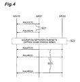
- Fig. 4 is an illustration for explaining an area determining process in the paging control mode.
- MN 10 in the paging control performs determination of the paging area with reference to RA. Specifically, when MN 10, receiving RAs from AR 21 at S21, moves between different subnets in the same paging area (S22), it comes to receive RAs from AR 22 (S23). Since this causes a change of the network prefix value in RAs, MN 10 can detect a migration of itself between subnets. At this time, MN 10 in the paging control generates a c/o address (CoA: Care of Address) inside MN 10. However, MN 10 continuously stays in the paging control mode, without transmitting any packet to the other nodes including routers, different from the normal mode.
- CoA Care of Address
- Fig. 5 is an illustration for explaining an area update process in the paging control mode.
- MN 10 in the paging control performs an update of the paging area with reference to RA. Specifically, when MN 10, receiving an RA from AR 21 at S31, moves between subnets in different paging areas (S32), it comes to receive an RA from AR 22 (S33) . Since it causes a change of the paging area indicated by the network prefix value in RA, MN 10 can detect the migration between paging areas.
- MN 10 When MN 10 determines that it has moved out of a paging area, it transmits a paging request packet to PA 30 (S34). Then MN 10 receives a paging request response packet from PA 30 (S35), and thereafter MN 10 creates a new paging area, and continuously stays in the previous paging control mode. This completes re-registration of paging between MN 10 and PA 30.
- Fig. 6 is an illustration for explaining a restoration process from the paging control mode to the normal mode.
- MN 10 in the paging control When MN 10 in the paging control generates data packets to be transmitted via MA 40 by itself, it starts the restoration process to the normal mode.
- MN 10 sets a retention time of a paging registration cache to a sufficiently short time within a range where there occurs no state mismatch, and transmits a paging cancellation request packet to PA 30 (S41). . This cancels the registration of the paging control mode of MN 10, at PF. 30.
- PA 30 sends a paging cancellation confirmation packet back and MN 10 receives it.
- MN 10 transmits a BU to establish a packet forwarding path, to MA 40 (S43), thereby registering the address in the subnet where MN 10 is present, at MA 40.
- MA 40 sends a BA back and MN 10 receives it.
- MN 10 is restored to the normal mode and MN 10 starts transmitting the data packets according to a mobility management protocol implemented (S45). Since PA 30 has no fixed management area as described above, it can reduce the burden of maintenance on the network operator.
- the scheme is based on the assumption that MN 10 has a packet-communicable state and an incommunicable state with MA 40.
- the communicable state refers to a state in which the setting of packet forwarding of MN 10 is active at MA 40. More specifically, it is a state in which a binding cache is retained.
- the incommunicable state is a state in which the setting of packet forwarding of MN 10 is inactive, i.e., a state in which MN 10 is not registered at MA 40.
- the communicable state further comprises a normal mode M1 and a paging control mode M2.
- a transition from the normal mode M1 into the paging control mode M2 (T1) occurs as triggered by an event in which transmission/reception of data packet via MA 40 is not detected for a time interval predetermined by a timer of MN 10 (a timeout).
- MN 10 once having moved into the paging control mode M2 is restored to the normal mode M1 as triggered by either reception of a paging packet from PA 30 or generation of a packet via NIA 40 (T2).
- the time and the number of packets as parameters of above-referenced expression (1) are managed by the paging controller 35.
- the setting time of the timer used in the transition into the paging control mode M2 is preferably controlled as follows. For example, where the continuation times of the paging control mode M2 in the most recent several transitions do not satisfy the above expression (1), the setting time is lengthened to decrease the frequency of transitions into the paging control mode M2. A time interval without transmission/reception of packet via MA 40 is measured in the normal mode M1 and this time interval is regarded as T p . When this results in satisfying the above expression (1), the setting time of the timer is shortened to increase the frequency of transitions into the paging control mode M2.
- a term in the integral symbol is a probability density function of gamma distribution.
- An average of the continuation times of the paging mode is equal to c*b.
- "t" which gives above probability is calculated by Newton-Way and "t” is used as paging mode transition timer Td.
- setting values further required are "c”, and a parameter (e.g. tolerance, the number of maximum repeat times) for Newton-Way.
- a parameter e.g. tolerance, the number of maximum repeat times
- the aspect described in the above embodiment is just a preferred example of the paging control system according to the present invention, and the present invention is not limited to such aspect.
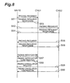
- An aspect in which MN 10 directly executes the paging control with CNs (Correspondent Nodes) 51, 52 as communication partner nodes will be described below with reference to Fig. 8 .
- the present aspect is similar to the aforementioned paging control technology described with Figs. 2 to 7 , expect that CNs 51, 52 instead of PA 30 are used as paging control apparatus. Therefore, the detailed description of this aspect will be omitted, but MN 10 and CNs 51, 52 perform transmission/reception of packet without passage via MA 40, in order to accomplish optimization of path.
- MN 10 transmits a paging request packet to each of CN 51 and CN 52 described in the cache of MN 10 (S51, S52). At this time, MN 10 sets paging control information including a paging area, an intermittent reception period for power saving control, and so on. Thereafter, MN 10 receives paging request response packets sent back from the respective CNs 51, 52 (S53, S54).
- the transition into the paging control mode can also be carried out independently for each of the communication partner nodes (CN 51, CN 52).
- CN 52 After CN 52 makes a transition into the paging control mode, it transmits a paging request packet to MN 10 as a communication partner (S55). Since at this point MN 10 is also in the paging control mode, the paging request packet may be directly broadcast in the paging area, or a paging notification packet may be transmitted to MN 10 to once restore MN 10 to the normal mode. At S56, MN 10 transmits a paging request response packet to CN 52.
- CN 51 transmits a paging notification packet to MN 10, in order to page MN 10 (S57).
- MN 10 sends back a paging notification confirmation packet (S58).
- MN 10 is restored to the mobility management control state being the normal mode and also sends a paging cancellation request packet to CN 52, in order to notify CN 52 of the change of the mode (S59).
- CN 52 sends a paging cancellation confirmation packet back (S60).
- MN 10 always monitors the communication state such as the volume of packets transmitted or received and the operation state such as the migration frequency, and selects and activates an appropriate mobility management protocol according to change of these states.
- the mobility management protocol is a protocol associated with the IP paging
- the system appropriately implements the notification of initiation of paging to MN 10 and the control of the paging area (paging control). This permits MN 10, even in paging, to securely receive a data packet directed to itself, regardless of the transition between subnets or regardless of the transition between paging areas.
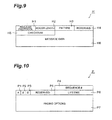
- Fig. 9 is an illustration showing an example of paging header which is applicable to the present invention.
- Payload Protocol field H1 is a 8-bit field to discriminate a head part of the paging header and is also used to discriminate a protocol type.
- Header Length field H2 is a 8-bit field which shows data length of the paging header.
- PH type field H3 is a 8-bit field to discriminate a type of the paging header.
- Reserved field H4 is a data field that will be used for extension in future.
- Checksum field H5 is a 16-bit field to detect errors when the paging header is transmitted.
- Message Data field H6 is a variable length field in which the above-described PH type data is stored.
- DMR Downlink Management message
- DMA Downlink Management message
- AMR Active Mode Request message
- AMA Active Mode Acknowledgement message
- PR Paging Request
- Fig. 10 is an illustration showing an example of the DMR.
- Acknowledge (A) field P1 is a field to require DMA to return to receipt of the DMR.
- Buffering (B) field P2 is a field to request a PA to store packets destined to a MN until the receipt of the AMR.
- Duplicate Address Detection (D) field P3 is a field to request a PA to detect duplicate address for Paging CoA.
- Sequence# field P4 is a 16-bit field to be used for matching a returned DMA with a sequence DMR.
- Reserved field P5 is a data field that will be used for extension in future.
- Lifetime field P6 is a 16-bit field in which the number of time units remaining before the binding is held.
- Paging Options field P7 is a variable-length optional field in which zero or more TLV-encoded is stored.
- the present invention is not limited to the above embodiments, but can also be suitably modified in various modification forms within the scope not departing from the spirit thereof.
- the above embodiment exemplified the IP layer as a layer for the paging control, but the technology according to the present invention is not limited only to this example, but can also be applied to the transport layer (UDP (User Datagram Protocol) layer, TCP (Transmission Control Protocol) layer, etc.) and the application layer.
- UDP User Datagram Protocol
- TCP Transmission Control Protocol
Landscapes
- Engineering & Computer Science (AREA)
- Computer Networks & Wireless Communication (AREA)
- Signal Processing (AREA)
- Mobile Radio Communication Systems (AREA)
- Data Exchanges In Wide-Area Networks (AREA)
Claims (12)
- Funkrufsteuerungsvorrichtung, welche die Verwaltung von Funkrufzuständen und Funkrufbereichen in Übereinstimmung mit einem Zustand eines mobilen Knotens durchführt, aufweisend:Empfangsmittel zum Empfang eines Pakets einer Funkrufanforderung, das von einem mobilen Knoten gesendet wird, um einen Übergang in einen Funkrufsteuerungsmodus anzufordern,Bestimmungsmittel, um einen Funkrufbereich als Reaktion auf das Paket zur Funkrufanforderung, welches durch das Empfangsmittel empfangen wurde, zu bestimmen;Benachrichtigungsmittel, um den mobilen Knoten über den Funkrufbereich zu benachrichtigen, welcher durch das Bestimmungsmittel bestimmt wurde;Steuerungsmittel, um den Funkrufbereich zu steuern, der durch das Bestimmungsmittel bestimmt wurde;Übergangsmittel, um den Übergang des mobilen Knotens in den Funkrufsteuerungsmodus zu veranlassen; undSendemittel, um Funkrufpakete in den Funkrufbereichen in Übereinstimmung mit dem Empfang von Datenpaketen, die an den mobilen Knoten gerichtet sind, auf Weiterleitungswegen in den Funkrufbereichen zu senden, und zum Weiterleiten der Datenpakete, wie sie zwischengespeichert sind an den mobilen Knoten beim Funkrufen, wie ausgelöst durch das Zurücksenden eines Funkrufbenachrichtigungs-Bestätigungspakets auf die Funkrufpakete.
- Funkrufsteuerungsvorrichtung nach Anspruch 1, weiter aufweisend Mittel zur Steuerung eines Zwischenspeichers, um eine derartige Steuerung durchzuführen, dass der Zwischenspeicher ein an den mobilen Knoten gerichtetes Datenpaket im Funkrufsteuerungsmodus zwischenspeichert.
- Mobiler Knoten zur Durchführung des Sendens /Empfangens eines Pakets an oder von der Funkrufsteuerungsvorrichtung nach Anspruch 1, welche daran angepasst ist, die Verwaltung von Funkrufzuständen und Funkrufbereichen in Übereinstimmung mit einem Zustand des mobilen Knotens durchzuführen, wobei der mobile Knoten aufweist: Einstellmittel zum Einstellen einer Zeit von einem Beginn eines normalen Modus bis zu einem Übergang zu einem Funkrufsteuerungsmodus;
Funkrufanforderungsmittel, um ein Paket zur Anforderung eines Funkrufs an die Funkrufsteuerungsvorrichtung zu senden, um einen Übergang zu einem Funkrufsteuerungsmodus anzufordern, in Übereinstimmung mit dem Verstreichen der Zeit, welche durch das Einstellmittel eingestellt wurde;
Weiterleitungsinstruktionsmittel, um an eine Mobilitätssteuerungsvorrichtung ein BU- Paket zu senden, um die Weiterleitung eines Datenpakets an die Funkrufsteuerungsvorrichtung anzuordnen, in Übereinstimmung mit dem Verstreichen der Zeit, die durch das Einstellmittel eingestellt wurde; und
Empfangsmittel, um ein Paket zur Bestätigung der Funkrufbenachrichtigung in Übereinstimmung mit dem Empfang von Funkrufpaketen, die von der Funkrufsteuerungsvorrichtung beim Funkrufen gesendet wurden, zurückzusenden, und um das Datenpaket, das in der Funkrufsteuerungsvorrichtung zwischengespeichert ist, weiterzuleiten. - Funkrufsteuerungssystem, das eine Funkrufsteuerungsvorrichtung aufweist, welche daran angepasst ist, die Verwaltung von Funkrufzuständen und Funkrufbereichen in Übereinstimmung mit einem Zustand eines mobilen Knotens durchzuführen, aufweisend:Empfangsmittel zum Empfang eines Paketes für eine Funkrufanforderung, das von einem mobilen Knoten gesendet wird, um einen Übergang in einen Funkrufsteuerungsmodus anzufordern;Bestimmungsmittel, um einen Funkrufbereich als Reaktion auf das Paket zur Funkrufanforderung zu bestimmen, das durch das Empfangsmittel empfangen wurde;Benachrichtigungsmittel, um den mobilen Knoten über den Funkrufbereich, der durch das Bestimmungsmittel bestimmt wurde, zu benachrichtigen;Steuerungsmittel, um den durch das Bestimmungsmittel bestimmten Funkrufbereich zu steuern,Übergangsmittel, um den Übergang des mobilen Knotens in einen Funkrufsteuerungsmodus zu veranlassen; undSendemittel, um Funkrufpakete auf Weiterleitungswegen in den Funkrufbereichen in Übereinstimmung mit dem Empfang von Datenpaketen, die an den Mobilknoten gerichtet sind, weiterzuleiten, und zum Weiterleiten der Datenpakete, wie sie zwischengespeichert sind, an den mobilen Knoten beim Funkrufen, wie ausgelöst durch das Zurücksenden eines Pakets zur Bestätigung einer Funkrufbenachrichtigung auf die Funkrufpakete, undden mobilen Knoten, um das Senden/Empfangen eines Pakets zu oder von der Funkrufsteuerungsvorrichtung durchzuführen, welche daran angepasst ist, die Verwaltung von Funkrufzuständen und Funkrufbereichen in Übereinstimmung mit einem Zustand des mobilen Knotens durchzuführen, wobei der mobile Knoten aufweist:Einstellmittel, um eine Zeit von einem Beginn eines Normalmodus bis zu einem Übergang in einen Funkrufsteuerungsmodus einzustellen;Funkrufanforderungsmittel, um ein Paket zur Anforderung eines Funkrufes an die Funkrufsteuerungsvorrichtung zu senden, um den Übergang in einen Funkrufsteuerungsmodus anzufordern; in Übereinstimmung mit dem Verstreichen der Zeit, die durch das Einstellmittel eingestellt wurde; undWeiterleitungsanordnungsmittel, um an eine Mobilitätssteuerungsvorrichtung ein BU- Paket zu senden, um die Weiterleitung eines Datenpakets an die Funkrufsteuerungsvorrichtung anzuordnen, in Übereinstimmung mit dem Verstreichen der Zeit, die durch das Einstellmittel eingestellt wurde; undEmpfangsmittel zum Zurücksenden eines Pakets zur Bestätigung einer Funkrufbenachrichtigung in Übereinstimmung mit dem Empfang von Funkrufpaketen, die von der Funkrufsteuerungsvorrichtung beim Funkrufen gesendet wurden, und zum Empfangen der Weiterleitung des Datenpakets, das durch die Funkrufsteuerungsvorrichtung zwischengespeichert wurde, worin die Funkrufsteuerungsvorrichtung betreibbar ist, um das Paket zur Anforderung eines Funkrufs, das vom mobilen Knoten gesendet wurde, zu empfangen.
- Verfahren zur Funkrufsteuerung, das die folgenden Schritte aufweist, welche durch eine Funkrufsteuerungsvorrichtung ausgeführt werden:einen Empfangsschritt, um ein Paket zur Anforderung eines Funkrufs zu empfangen, welches von einem mobilen Knoten gesendet wurde, um einen Übergang in einen Funkrufsteuerungsmodus anzufordern;einen Bestimmungsschritt, um einen Funkrufbereich als Reaktion auf das Paket zur Anforderung eines Funkrufs zu bestimmen, das im Empfangsschritt empfangen wurde; einen Benachrichtigungsschritt, um den mobilen Knoten über den Funkrufbereich zu benachrichtigen, der im Bestimmungsschritt bestimmt wurde;einen Steuerungsschritt, um den Funkrufbereich, der durch den Bestimmungsschritt bestimmt wurde, zu steuern;einen ersten Übergangsschritt, um den Übergang in den Funkrufsteuerungsmodus zu veranlassen;einen ersten Sendeschritt, worin, wenn die Funkrufsteuerungsvorrichtung ein Datenpaket, das an den mobilen Knoten gerichtet ist, welche einen Funkrufbereich aufweist, detektiert, die Funkrufsteuerungsvorrichtung ein an den mobilen Knoten gerichtetes Paket zur Benachrichtigung eines Funkrufs auf allen Weiterleitungswegen im Funkrufbereich sendet;einen Halteschritt, in dem die Funkrufsteuerungsvorrichtung ein Datenpaket in einem Zwischenspeicher hält, bis die Funkrufsteuerungsvorrichtung ein Paket zur Bestätigung der Funkrufbenachrichtigung vom mobilen Knoten empfängt;einen Weiterleitungsschritt, worin nach dem Empfang des Pakets zur Bestätigung der Funkrufbenachrichtigung die Funkrufsteuerungsvorrichtung das Datenpaket, das im Halteschritt gehalten wurde, an den mobilen Knoten beim Funkrufen über einen Weiterleitungsweg sendet, der durch das Paket zur Bestätigung der Funkrufbenachrichtigung bestimmt ist; undeinen zweiten Sendeschritt, in dem die Funkrufsteuerungsvorrichtung Funkrufpakete auf Weiterleitungswegen in den Funkrufbereichen in Übereinstimmung mit dem Empfang von Datenpaketen, die an den mobilen Knoten gerichtet sind, sendet und die Datenpakete, wie zwischengespeichert, an den mobilen Knoten beim Funkrufen sendet, wie ausgelöst durch das Zurücksenden eines Pakets zur Bestätigung der Funkrufbenachrichtigung auf die Funkrufpakete.
- Funkrufsteuerungsverfahren nach Anspruch 5, weiter aufweisend die folgenden Schritte, welche durch einen mobilen Knoten ausgeführt werden, der in der Lage ist, gemäß einer Vielzahl von Mobilitätsverwaltungsprotokollen betrieben zu werden:einen Auswahlschritt, in dem der mobile Knoten ein Mobilitätsverwaltungsprotokoll auswählt, das betrieben werden soll, basierend auf einem Kommunikationszustand und einem Betriebszustand des mobilen Knotens; undeinen Kommunikationsschritt, in dem der mobile Knoten das Senden/Empfangen eines Datenpakets basierend auf dem Mobilitätsverwaltungsprotokoll durchführt, das im Auswahlschritt ausgewählt wurde.
- Das Funkrufsteuerungsverfahren nach Anspruch 6, bei dem im ersten Sendeschritt, wenn der mobile Knoten kein Datenpaket, das an den mobilen Knoten gerichtet ist, detektiert, welches über die Mobilitätssteuerungsvorrichtung für einen bestimmten Zeitraum gesendet oder empfangen wird, der mobile Knoten einen normalen Modus beendet und den Übergang in einen Funkrufsteuerungsmodus durchführt.
- Das Funkrufsteuerungsverfahren nach Anspruch 7, weiter aufweisend einen zweiten Bestimmungsschritt, in dem der mobile Knoten die vorbestimmte Zeit als Auslöser für den Übergang in den Funkrufsteuerungsmodus im ersten Sendeschritt detektiert, unter Verwendung wenigstens einer mittleren Fortführungszeit des Funkrufsteuerungsmodus in der Vergangenheit oder eines mittleren auftretenden Zeitabschnitts für die Übergabe.
- Das Funkrufsteuerungsverfahren nach Anspruch 7, weiter aufweisend einen zweiten Übergangsschritt, in dem, wenn der mobile Knoten im Funkrufsteuerungsmodus das Senden /Empfangen eines an den mobilen Knoten gerichteten Datenpakets über eine Mobilitätssteuerungsvorrichtung detektiert, der mobile Knoten den Funkrufsteuerungsmodus beendet und wiederum einen Übergang in den normalen Modus durchführt.
- Das Funkrufsteuerungsverfahren nach Anspruch 9, weiter aufweisend einen dritten Übergangsschritt, worin, wenn der mobile Knoten das Senden /Empfangen eines an den mobilen Knoten gerichteten Datenpakets über einen Kommunikationspartnerknoten für einen bestimmten Zeitraum nicht detektiert, der mobile Knoten einen normalen Modus beendet und einen Übergang in einen Funkrufsteuerungsmodus durchführt.
- Das Funkrufsteuerungsverfahren nach Anspruch 10, weiter aufweisend einen vierten Übergangsschritt, worin, wenn der mobile Knoten im Funkrufmodus das Senden/Empfangen von einem an den mobilen Knoten gerichteten Datenpaket über den Kommunikationspartnerknoten detektiert, der mobile Knoten den Funkrufsteuerungsmodus beendet und wiederum einen Übergang in den normalen Modus durchführt.
- Das Funkrufsteuerungsverfahren nach Anspruch 6, weiter aufweisend einen Funkrufsteuerungsschritt, in dem der mobile Knoten ein an den mobilen Knoten gerichtetes Datenpaket detektiert und die Vielzahl der Mobilitätsverwaltungsprotokolle basierend auf dem Ergebnis der Detektion ändert.
Applications Claiming Priority (2)
| Application Number | Priority Date | Filing Date | Title |
|---|---|---|---|
| JP2003160004 | 2003-06-04 | ||
| JP2003160004 | 2003-06-04 |
Publications (2)
| Publication Number | Publication Date |
|---|---|
| EP1484863A1 EP1484863A1 (de) | 2004-12-08 |
| EP1484863B1 true EP1484863B1 (de) | 2008-03-26 |
Family
ID=33157188
Family Applications (1)
| Application Number | Title | Priority Date | Filing Date |
|---|---|---|---|
| EP04013272A Expired - Fee Related EP1484863B1 (de) | 2003-06-04 | 2004-06-04 | Funkrufsteuerungsvorrichtung, mobiler Knoten, Funkrufsteuerungssystem und Funkrufsteuerungsvefahren |
Country Status (5)
| Country | Link |
|---|---|
| US (1) | US20050003836A1 (de) |
| EP (1) | EP1484863B1 (de) |
| KR (1) | KR100701808B1 (de) |
| CN (1) | CN100346666C (de) |
| DE (1) | DE602004012655T2 (de) |
Cited By (1)
| Publication number | Priority date | Publication date | Assignee | Title |
|---|---|---|---|---|
| JP2009512362A (ja) * | 2005-10-14 | 2009-03-19 | インテル コーポレイション | 無線ページング装置、システム及び方法 |
Families Citing this family (24)
| Publication number | Priority date | Publication date | Assignee | Title |
|---|---|---|---|---|
| EP1091517A1 (de) | 1999-10-07 | 2001-04-11 | Siemens Aktiengesellschaft | Verfahren und System zur Übertragung von punktierten oder wiederholten Daten |
| US7149807B1 (en) * | 2001-02-02 | 2006-12-12 | Akamai Technologies, Inc. | Control and communication infrastructure (CCI) for selecting a transport mechanism to transport data to one or more servers in a content delivery network based on the size of the data, together with frequency and loss tolerance with respect to transport of the data |
| US20060099972A1 (en) * | 2004-11-08 | 2006-05-11 | Nair Sureshbabu P | Method and apparatus for paging an idle mobile unit in a distributed network |
| US7313394B2 (en) | 2005-07-15 | 2007-12-25 | Intel Corporation | Secure proxy mobile apparatus, systems, and methods |
| US7693555B2 (en) | 2005-10-21 | 2010-04-06 | Intel Corporation | Sleep-mode wireless cell reselection apparatus, systems, and methods |
| CN100461955C (zh) * | 2006-01-09 | 2009-02-11 | 华为技术有限公司 | 一种移动通信系统中寻呼优化的实现方法 |
| CN101064957B (zh) * | 2006-04-26 | 2011-06-08 | 华为技术有限公司 | 信息更新方法 |
| KR100819403B1 (ko) * | 2006-12-05 | 2008-04-04 | 삼성전자주식회사 | 시그널링 부하를 줄이기 위한 장치 및 방법 |
| US9049690B2 (en) * | 2006-12-27 | 2015-06-02 | Kyocera Corporation | Communication system, wireless communication terminal, communication method, wireless communication method, wireless communication apparatus and control method thereof |
| WO2008093069A1 (en) * | 2007-01-31 | 2008-08-07 | British Telecommunications Public Limited Company | Communications system and method |
| US8611921B2 (en) * | 2007-04-06 | 2013-12-17 | Qualcomm Incorporated | Delay and backhaul-efficient paging method and apparatus |
| US8520698B2 (en) | 2007-09-04 | 2013-08-27 | Qualcomm Incorporated | Paging user devices in a wireless access network |
| US8156353B2 (en) * | 2007-09-17 | 2012-04-10 | Intel Corporation | Techniques for communications power management based on system states |
| US8312307B2 (en) | 2007-11-07 | 2012-11-13 | Intel Corporation | Systems and methods for reducing power consumption during communication between link partners |
| US8442560B1 (en) | 2007-11-19 | 2013-05-14 | Kenneth P. Kiraly | Mode switching user device |
| US8078184B2 (en) * | 2008-05-08 | 2011-12-13 | Research In Motion Limited | Method and apparatus having improved handling of state transitions |
| US8213303B2 (en) | 2008-09-12 | 2012-07-03 | Intel Corporation | Generating, at least in part, and/or receiving, at least in part, at least one request |
| US8201005B2 (en) | 2009-03-17 | 2012-06-12 | Intel Corporation | Negotiating a transmit wake time |
| WO2011113198A1 (en) | 2010-03-17 | 2011-09-22 | Qualcomm Incorporated | Apparatus and method for interference mitigation |
| US20110307079A1 (en) * | 2010-04-29 | 2011-12-15 | Board Of Trustees Of Michigan State University, The | Multiscale intra-cortical neural interface system |
| US8725145B2 (en) * | 2011-01-25 | 2014-05-13 | Qualcomm Incorporated | Mobile device requests of non-communication time periods to a wireless communication network |
| EP2814295A4 (de) | 2012-01-16 | 2016-01-06 | Nec Corp | Vorrichtung zur steuerung eines funkrufbereichs und verfahren, übertragungsvorrichtung, mobiles kommunikationssystem, mobilstation sowie computerlesbares medium |
| CN104469944B (zh) * | 2014-12-01 | 2018-06-15 | 中国科学院计算机网络信息中心 | 一种基于PMIPv6的本地化寻呼方法 |
| JP6271770B2 (ja) * | 2015-01-22 | 2018-01-31 | 株式会社Nttドコモ | ページング制御方法、及び通信制御装置 |
Family Cites Families (9)
| Publication number | Priority date | Publication date | Assignee | Title |
|---|---|---|---|---|
| US5369681A (en) * | 1992-05-12 | 1994-11-29 | Telefonaktiebolaget L M Ericsson | Cellular communications system utilizing paging areas |
| US5924042A (en) * | 1995-03-15 | 1999-07-13 | Kabushiki Kaisha Toshiba | Mobile communication system |
| US6836651B2 (en) * | 1999-06-21 | 2004-12-28 | Telespree Communications | Portable cellular phone system having remote voice recognition |
| US6542517B1 (en) * | 1999-05-11 | 2003-04-01 | Qualcomm Incorporated | System and method for operating a mobile station in voice mode or pager mode |
| JP3344472B2 (ja) * | 1999-05-20 | 2002-11-11 | 日本電気株式会社 | 移動通信方法 |
| US6594493B1 (en) * | 2000-02-09 | 2003-07-15 | Lucent Technologies Inc. | Paging arrangement for wireless communications |
| US7120453B2 (en) * | 2000-04-18 | 2006-10-10 | Lucent Technologies Inc. | Paging of mobile hosts on an internet protocol network |
| US7142520B1 (en) | 2000-06-16 | 2006-11-28 | Nokia Mobile Phones Ltd. | Method and apparatus for mobile internet protocol regional paging |
| US7283496B2 (en) * | 2001-10-17 | 2007-10-16 | Alcatel Lucent | Network paging system and method |
-
2004
- 2004-06-04 CN CNB2004100480274A patent/CN100346666C/zh not_active Expired - Fee Related
- 2004-06-04 DE DE602004012655T patent/DE602004012655T2/de active Active
- 2004-06-04 US US10/859,983 patent/US20050003836A1/en not_active Abandoned
- 2004-06-04 EP EP04013272A patent/EP1484863B1/de not_active Expired - Fee Related
- 2004-06-04 KR KR1020040041010A patent/KR100701808B1/ko not_active IP Right Cessation
Cited By (1)
| Publication number | Priority date | Publication date | Assignee | Title |
|---|---|---|---|---|
| JP2009512362A (ja) * | 2005-10-14 | 2009-03-19 | インテル コーポレイション | 無線ページング装置、システム及び方法 |
Also Published As
| Publication number | Publication date |
|---|---|
| CN1575023A (zh) | 2005-02-02 |
| CN100346666C (zh) | 2007-10-31 |
| KR20040104940A (ko) | 2004-12-13 |
| US20050003836A1 (en) | 2005-01-06 |
| KR100701808B1 (ko) | 2007-04-02 |
| EP1484863A1 (de) | 2004-12-08 |
| DE602004012655D1 (de) | 2008-05-08 |
| DE602004012655T2 (de) | 2009-04-30 |
Similar Documents
| Publication | Publication Date | Title |
|---|---|---|
| EP1484863B1 (de) | Funkrufsteuerungsvorrichtung, mobiler Knoten, Funkrufsteuerungssystem und Funkrufsteuerungsvefahren | |
| US7424295B2 (en) | Handover control apparatus, base station, edge router, relay router, radio terminal unit, mobile communication system, and handover control method | |
| US8175057B2 (en) | Method and system for fast handovers using dynamic router advertisements | |
| EP2109978B1 (de) | Kommunikationsverfahren, -system und vorrichtung | |
| US8284743B2 (en) | Maintaining prefix consistency in dynamic moving networks | |
| US7710905B2 (en) | Link latency determination for optimal mobile IP re-registration | |
| US7710921B2 (en) | Transmitted packet replenishment system and transmitted packet replenishing method | |
| US8254929B2 (en) | Mobile communication method and mobile communication apparatus | |
| EP1833204A1 (de) | Schnelle Konfiguration von einem voreingstellten Router für einen mobilen Knoten in einem mobilen Kommunikationssystem | |
| Zinonos et al. | Inter-mobility support in controlled 6LoWPAN networks | |
| WO2005117367A1 (ja) | 移動端末管理装置及び移動端末並びに通信システム | |
| EP1278348A1 (de) | Langlebige TCP Verbindungen mit ICMP Nachrichten in drahtlosen Kommunikationsnetzwerken | |
| Eom et al. | Improving TCP handoff performance in Mobile IP based networks | |
| US20080253329A1 (en) | Communication Handover Method, Communication System, Communication Message Processing Method, and Communication Message Processing Program | |
| JP2005020726A (ja) | ページング制御装置、移動ノード、ページング制御システム、及びページング制御方法 | |
| Liu et al. | S-PMIPv6: Efficient handover of proxy mobile IPv6 by using SCTP | |
| KR100707533B1 (ko) | 무선 인터넷의 패킷 전송 방법 | |
| Wang et al. | Link layer assisted IP mobility protocol |
Legal Events
| Date | Code | Title | Description |
|---|---|---|---|
| PUAI | Public reference made under article 153(3) epc to a published international application that has entered the european phase |
Free format text: ORIGINAL CODE: 0009012 |
|
| 17P | Request for examination filed |
Effective date: 20040604 |
|
| AK | Designated contracting states |
Kind code of ref document: A1 Designated state(s): AT BE BG CH CY CZ DE DK EE ES FI FR GB GR HU IE IT LI LU MC NL PL PT RO SE SI SK TR |
|
| AX | Request for extension of the european patent |
Extension state: AL HR LT LV MK |
|
| 17Q | First examination report despatched |
Effective date: 20050202 |
|
| AKX | Designation fees paid |
Designated state(s): DE GB |
|
| GRAP | Despatch of communication of intention to grant a patent |
Free format text: ORIGINAL CODE: EPIDOSNIGR1 |
|
| GRAS | Grant fee paid |
Free format text: ORIGINAL CODE: EPIDOSNIGR3 |
|
| GRAA | (expected) grant |
Free format text: ORIGINAL CODE: 0009210 |
|
| AK | Designated contracting states |
Kind code of ref document: B1 Designated state(s): DE GB |
|
| REG | Reference to a national code |
Ref country code: GB Ref legal event code: FG4D |
|
| REF | Corresponds to: |
Ref document number: 602004012655 Country of ref document: DE Date of ref document: 20080508 Kind code of ref document: P |
|
| PLBE | No opposition filed within time limit |
Free format text: ORIGINAL CODE: 0009261 |
|
| STAA | Information on the status of an ep patent application or granted ep patent |
Free format text: STATUS: NO OPPOSITION FILED WITHIN TIME LIMIT |
|
| 26N | No opposition filed |
Effective date: 20081230 |
|
| PGFP | Annual fee paid to national office [announced via postgrant information from national office to epo] |
Ref country code: GB Payment date: 20130529 Year of fee payment: 10 Ref country code: DE Payment date: 20130529 Year of fee payment: 10 |
|
| REG | Reference to a national code |
Ref country code: DE Ref legal event code: R119 Ref document number: 602004012655 Country of ref document: DE |
|
| GBPC | Gb: european patent ceased through non-payment of renewal fee |
Effective date: 20140604 |
|
| REG | Reference to a national code |
Ref country code: DE Ref legal event code: R119 Ref document number: 602004012655 Country of ref document: DE Effective date: 20150101 |
|
| PG25 | Lapsed in a contracting state [announced via postgrant information from national office to epo] |
Ref country code: DE Free format text: LAPSE BECAUSE OF NON-PAYMENT OF DUE FEES Effective date: 20150101 |
|
| PG25 | Lapsed in a contracting state [announced via postgrant information from national office to epo] |
Ref country code: GB Free format text: LAPSE BECAUSE OF NON-PAYMENT OF DUE FEES Effective date: 20140604 |