EP1484631A1 - Integrated optoelectronic device comprising an electroabsorption modulator and its electronic control element - Google Patents
Integrated optoelectronic device comprising an electroabsorption modulator and its electronic control element Download PDFInfo
- Publication number
- EP1484631A1 EP1484631A1 EP04291368A EP04291368A EP1484631A1 EP 1484631 A1 EP1484631 A1 EP 1484631A1 EP 04291368 A EP04291368 A EP 04291368A EP 04291368 A EP04291368 A EP 04291368A EP 1484631 A1 EP1484631 A1 EP 1484631A1
- Authority
- EP
- European Patent Office
- Prior art keywords
- sections
- optoelectronic device
- modulator
- modulation
- optical
- Prior art date
- Legal status (The legal status is an assumption and is not a legal conclusion. Google has not performed a legal analysis and makes no representation as to the accuracy of the status listed.)
- Withdrawn
Links
Images
Classifications
-
- G—PHYSICS
- G02—OPTICS
- G02F—OPTICAL DEVICES OR ARRANGEMENTS FOR THE CONTROL OF LIGHT BY MODIFICATION OF THE OPTICAL PROPERTIES OF THE MEDIA OF THE ELEMENTS INVOLVED THEREIN; NON-LINEAR OPTICS; FREQUENCY-CHANGING OF LIGHT; OPTICAL LOGIC ELEMENTS; OPTICAL ANALOGUE/DIGITAL CONVERTERS
- G02F1/00—Devices or arrangements for the control of the intensity, colour, phase, polarisation or direction of light arriving from an independent light source, e.g. switching, gating or modulating; Non-linear optics
- G02F1/01—Devices or arrangements for the control of the intensity, colour, phase, polarisation or direction of light arriving from an independent light source, e.g. switching, gating or modulating; Non-linear optics for the control of the intensity, phase, polarisation or colour
- G02F1/015—Devices or arrangements for the control of the intensity, colour, phase, polarisation or direction of light arriving from an independent light source, e.g. switching, gating or modulating; Non-linear optics for the control of the intensity, phase, polarisation or colour based on semiconductor elements with at least one potential jump barrier, e.g. PN, PIN junction
- G02F1/017—Structures with periodic or quasi periodic potential variation, e.g. superlattices, quantum wells
- G02F1/01708—Structures with periodic or quasi periodic potential variation, e.g. superlattices, quantum wells in an optical wavequide structure
-
- B—PERFORMING OPERATIONS; TRANSPORTING
- B82—NANOTECHNOLOGY
- B82Y—SPECIFIC USES OR APPLICATIONS OF NANOSTRUCTURES; MEASUREMENT OR ANALYSIS OF NANOSTRUCTURES; MANUFACTURE OR TREATMENT OF NANOSTRUCTURES
- B82Y20/00—Nanooptics, e.g. quantum optics or photonic crystals
-
- G—PHYSICS
- G02—OPTICS
- G02F—OPTICAL DEVICES OR ARRANGEMENTS FOR THE CONTROL OF LIGHT BY MODIFICATION OF THE OPTICAL PROPERTIES OF THE MEDIA OF THE ELEMENTS INVOLVED THEREIN; NON-LINEAR OPTICS; FREQUENCY-CHANGING OF LIGHT; OPTICAL LOGIC ELEMENTS; OPTICAL ANALOGUE/DIGITAL CONVERTERS
- G02F1/00—Devices or arrangements for the control of the intensity, colour, phase, polarisation or direction of light arriving from an independent light source, e.g. switching, gating or modulating; Non-linear optics
- G02F1/01—Devices or arrangements for the control of the intensity, colour, phase, polarisation or direction of light arriving from an independent light source, e.g. switching, gating or modulating; Non-linear optics for the control of the intensity, phase, polarisation or colour
- G02F1/0121—Operation of devices; Circuit arrangements, not otherwise provided for in this subclass
-
- G—PHYSICS
- G02—OPTICS
- G02F—OPTICAL DEVICES OR ARRANGEMENTS FOR THE CONTROL OF LIGHT BY MODIFICATION OF THE OPTICAL PROPERTIES OF THE MEDIA OF THE ELEMENTS INVOLVED THEREIN; NON-LINEAR OPTICS; FREQUENCY-CHANGING OF LIGHT; OPTICAL LOGIC ELEMENTS; OPTICAL ANALOGUE/DIGITAL CONVERTERS
- G02F1/00—Devices or arrangements for the control of the intensity, colour, phase, polarisation or direction of light arriving from an independent light source, e.g. switching, gating or modulating; Non-linear optics
- G02F1/01—Devices or arrangements for the control of the intensity, colour, phase, polarisation or direction of light arriving from an independent light source, e.g. switching, gating or modulating; Non-linear optics for the control of the intensity, phase, polarisation or colour
- G02F1/015—Devices or arrangements for the control of the intensity, colour, phase, polarisation or direction of light arriving from an independent light source, e.g. switching, gating or modulating; Non-linear optics for the control of the intensity, phase, polarisation or colour based on semiconductor elements with at least one potential jump barrier, e.g. PN, PIN junction
- G02F1/0155—Devices or arrangements for the control of the intensity, colour, phase, polarisation or direction of light arriving from an independent light source, e.g. switching, gating or modulating; Non-linear optics for the control of the intensity, phase, polarisation or colour based on semiconductor elements with at least one potential jump barrier, e.g. PN, PIN junction modulating the optical absorption
Definitions
- the invention relates to the field of high-speed data transmission.
- fiber optic throughput and more particularly relates to a device integrated optoelectronics with a suitable electroabsorption modulator providing a modulated optical data carrier output signal, and a electronic control element capable of controlling said modulator.
- electroabsorption modulators discrete modulators and those with traveling waves.
- R s the series resistance of the modulator, R L ⁇ 50 ⁇ , the impedance of the control source, C m the capacity of the modulator.
- a discrete modulator operates correctly at 40 GHz, with a length of around 100 ⁇ m, a capacitance C m of around 70 fF and a series resistance R s of around 5 ⁇ .
- the cut-off frequency is greater the longer the length of the electrode is weak. To operate at high speed, for example at 80 or 160 Gbit / s, it would therefore be necessary to drastically reduce this length, with intrinsic zone thickness and guide width given. However, the reduction in length is accompanied by a decrease in efficiency optics translated by a low extinction rate, and requires voltages of very high command required, interaction distance optical / electrical is no longer sufficient.
- the traveling wave electroabsorption modulator (TWEAM for "traveling waves electrabsorption modulator” in English) is characterized by its electrode distributed so that there is double propagation: the propagation of guided light and the propagation of an electric wave. During their copropagation, there is transfer of the modulation energy of the electrical signal to optical signal.
- TWEAM traveling wave electroabsorption modulator
- Progressive wave electro-absorption modulators are in technology based on lithium niobiate or more recently, such as discrete modulators, in technology based on semiconductor materials III-V, of the InGaAsP type. These semiconductor materials have a voltage of control, therefore lower consumption and the modulators produced are less bulky.
- the traveling wave modulators theoretically allow to overcome of the problem of limiting electric bandwidth.
- the losses of the electric wave during its propagation the length of the electrode are important and impose a length limit for a fixed bandwidth.
- the characteristic impedance of the line of modulator propagation is generally too low compared to that of the control transistor, which limits the electrical power transmitted to the modulator.
- the voltage gain is too low at high frequency.
- Discrete and wave electro-absorption modulators progressive are therefore not efficient beyond 40 GHz.
- the object of the invention is to provide an optoelectronic device integrated with a space-saving electro-absorption modulator consumer, operating at high speed and producing one or more signals modulated optics having an extinction rate and an optical power satisfactory.
- the modulator electroabsorption according to the invention is distributed as is the amplification electric is distributed: each modulation section, electroabsorption, participates in the generation of a modulated optical signal which, at output, presents an extinction rate (in dB) corresponding to the sum of the extinction rates sections.
- the electronic control element according to the invention is chosen fast and has a high total voltage gain.
- This element is capable of supplying control signals, for example voltages of control, from peak to peak level sufficient and adjusted for each section modulation.
- the means of distributed electrical amplification are such as the control signal from the most upstream modulation section, which receives a continuous optical input signal, is of lower intensity than the signal control of the most downstream modulation section.
- At least one of said modulation sections receiving a modulated optical input signal some of said sections are phase adjustment means so as to phase, at the level at least said section, the control signal with said optical signal modulated input, to avoid data jamming.
- an optical amplifier preferably solid-state, of so as to compensate for optical losses.
- the modulation sections can each be traveling wave.
- the means of distributed electrical amplification may include a plurality of transistors with high electron mobility and preferably heterojunction bipolar transistors or field effect transistors such as' HEMT (HEMT in English for high electron mobility transistor). Said transistors are connected to the same other propagation line which is capable of carrying a modulated electrical signal, for example from a time multiplexer.
- the modulation sections can be aligned and the line of electrical propagation for control signals may have a form niche type and preferably include at the entry and exit means of impedance matching.
- the impedance of the electrical propagation line for control signals can thus be easily adjusted and reduced if necessary.
- the optoelectronic device may include a source of at least less a continuous optical signal, arranged upstream of said modulator by relative to the direction of optical propagation, such as a laser source, as well as a optical waveguide disposed downstream of said modulator with respect to the direction optical propagation.
- a source of at least less a continuous optical signal arranged upstream of said modulator by relative to the direction of optical propagation, such as a laser source, as well as a optical waveguide disposed downstream of said modulator with respect to the direction optical propagation.
- the device optoelectronics is monolithic and preferably produced on a substrate with indium phosphide base for great compactness.
- the modulator electroabsorption is carried out on a substrate based on indium phosphide, while the electronic control element is hybrid and is made in part on a separate substrate based on gallium arsenide or phosphide indium. And some of the sections, called interconnections, are chosen from gold ribbons, gold wires and other flexible conductive elements.
- the invention naturally applies to any transmission system incorporating the integrated optoelectronic device as defined previously.
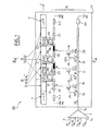
- FIG. 1 a top view which is not to the scale of a integrated optoelectronic device 100, in a preferred embodiment of the invention
- the optoelectronic device 100 is an integrated source of minus a high speed modulated optical signal insertable into a transmission (not shown) for example containing an optical fiber of transmission.
- the device 100 is preferably monolithic and produced on a substrate 111 of indium phosphide InP.
- the device 100 is designed to operate at high speed for example at 160 GHz, i.e. a modulation wavelength of 300 ⁇ m.
- each electrode 1, 2, 3 is distributed and chosen length less than or equal to 300 ⁇ m to form a line of transmission.
- the set of distributed electrical amplification means is formed of three electrical amplifiers 22, 23, 24, each consisting of a transistor with high electron mobility, for example preferably bipolar heterojunction.
- Each transmitter is connected to an earth M22, M23, M24.
- each of the transistors 22 to 24 heterojunction bipolar and followed by a second bipolar transistor with heterojunction mounted in 'cascode' to provide a control signal for best quality.
- transistors 22 to 24 may as well have the effect of field.
- Transistors 22 to 24 are connected by their collector to separate points A; B; C of the first line of electrical 21 which corresponds thus to an exit line.
- This first electrical line 21, substantially shaped in niche in particular for a gain in compactness, comprises a plurality of sections, for example sixteen, between an adaptation input impedance of line ZL2 connected to a ground M2 and an adaptation output impedance of line ZL3 connected to ground M3.
- These impedances ZL2, ZL3 can be distinct from 50 ⁇ .
- the impedances are adjusted by the choice of the width, by example equal to 20 ⁇ m, and of the length and are for example inductors worth approximately 100 nH / m.
- the bases of the transistors 22 to 24 are further connected by links LK1 to LK3 at separate points A ', B', C 'of the second line of electric 25 which thus corresponds to an input line.
- the second electric line 25 is thus divided into four sections referenced by their impedances Za to Zd each being adjusted by the choice width, preferably equal to 10 ⁇ m, and length.
- the impedances Za to Zd correspond for example to inductances of around 250 nH / m.
- This second electrical line 25 is itself connected at the input to a single output branch 6 5 of a time electrical multiplexer 6 with four input branches 6 1 to 6 4 and at the output to a load resistor ZL1, for example equal to 50 ⁇ or less, connected to ground M1.
- Transistors 22 to 24 are supplied with voltage Va, Vb, Vc from of the second power line 25 and provide electrical signals amplified modules which are control currents which generate control voltages V1, V2, V3 propagating in the first line electric 21.
- the voltage of command V2 is chosen according to the losses as well as the voltage of command V3 at the input of the third modulation section 13.
- a continuous optical signal S i of power for example equal to approximately 1 W, is generated by the laser source 4 and amplified by the amplifier 31.
- this signal S i is modulated at a rate of 160 Gbit / s by the control voltage V1 applied to electrode 1.
- the extinction rate is around 6 dB.
- the modulated optical signal S mod is then amplified by the amplifier 32 and injected into the second modulation section 12.
- the modulation is reinforced by the control voltage V2 in phase with this modulated optical signal, thanks to the section 21 a.
- the extinction rate is around 13 dB.
- a high speed modulated signal S f is obtained at the output of the guide 5 with a power of the order of at least 0 dBm and an extinction rate equal to 13 dB minimum.
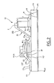
- Figure 2 schematically shows a partial view, in section lateral along axis II, which is not to scale, of the optoelectronic device integrated 100.
- the cut is made at the second section of modulation 12, as an example.
- the modulation section 12 has a vertical structure 7 which is a stack of epitaxial layers produced on the so-called upper face F1 of substrate 111.
- the electrode section 2 by example a titanium, platinum and gold multilayer 2 ⁇ m thick.
- the first line of electrical 25 for example a multilayer titanium, platinum and gold 2 ⁇ m thick is connected by the LK2 link to the base of transistor 23.
- the link LK2 and the interconnection sections 213, are also a titanium multilayer, platinum and gold formed for example on an insulating material such as polyimide (not shown).
- the electronic control element 20 is hybrid for ease of production and is partly produced on a separate substrate based on arsenide of gallium or gallium or indium phosphide.
- the sections interconnections 211 to 216 are then chosen from gold-based wires, gold-based tapes and other flexible conductive elements such as a ribbon polyimide coated with copper.
- Continuous source 4 electroabsorption modulator 30, series 30 of four optical amplifiers and the output optical guide 5 are manufactured on the substrate 111 in indium phosphide InP.
- modulation sections may as well be greater together. Their length is adjusted according to the desired performance.
Abstract
Description
L'invention concerne le domaine des transmission de données à haut débit sur fibres optiques et plus particulièrement porte sur un dispositif optoélectronique intégré comportant un modulateur à électroabsorption apte à délivrer un signal optique modulé de sortie porteur de données, et un élément électronique de commande apte à piloter ledit modulateur.The invention relates to the field of high-speed data transmission. fiber optic throughput and more particularly relates to a device integrated optoelectronics with a suitable electroabsorption modulator providing a modulated optical data carrier output signal, and a electronic control element capable of controlling said modulator.
De manière connue, pour fabriquer des sources de signaux optiques modulés porteurs de données, par exemple émettant à 1,55 µm, on peut utiliser un laser continu suivi d'un modulateur externe tel qu'un modulateur à électroabsorption (EAM pour "electrabsorption modulator" en anglais), commandé par une source en tension réalisée avec un transistor par exemple.In known manner, for manufacturing optical signal sources modulated data carriers, for example emitting at 1.55 µm, we can use a continuous laser followed by an external modulator such as a electroabsorption (EAM for "electrabsorption modulator" in English), controlled by a voltage source produced with a transistor by example.
Pour fonctionner à haut débit, de nombreuses recherches sont actuellement menées en particulier afin de réaliser une intégration du transistor de commande et du modulateur externe qui doivent être adaptés l'un à l'autre.To operate at high speed, a lot of research is currently being carried out in particular in order to achieve an integration of control transistor and external modulator which must be adapted to one another.
Par ailleurs, il existe deux types de modulateurs à électroabsorption les modulateurs discrets et ceux à ondes progressives.In addition, there are two types of electroabsorption modulators discrete modulators and those with traveling waves.
Concernant les modulateurs discret, la fréquence de coupure est
donnée par la relation :
RL ≈ 50 Ω, l'impédance de la source de commande,
Cm la capacité du modulateur.Concerning discrete modulators, the cutoff frequency is given by the relation:
R L ≈ 50 Ω, the impedance of the control source,
C m the capacity of the modulator.
Actuellement, un modulateur discret fonctionne correctement à 40 GHz, avec une longueur d'environ 100 µm, une capacité Cm d'environ 70 fF et une résistance série Rs d'environ 5 Ω.Currently, a discrete modulator operates correctly at 40 GHz, with a length of around 100 µm, a capacitance C m of around 70 fF and a series resistance R s of around 5 Ω.
La fréquence de coupure est d'autant plus grande que la longueur de l'électrode est faible. Pour fonctionner à haut débit, par exemple à 80 ou 160 Gbit/s, il serait donc nécessaire de réduire drastiquement cette longueur, à épaisseur de zone intrinsèque et largeur de guide données. Toutefois, la réduction de la longueur s'accompagne d'une diminution de l'efficacité optique traduite par un faible taux d'extinction, et nécessite des tensions de commande nécessaires très élevées, la distance d'interaction optique/électrique n'étant plus suffisante.The cut-off frequency is greater the longer the length of the electrode is weak. To operate at high speed, for example at 80 or 160 Gbit / s, it would therefore be necessary to drastically reduce this length, with intrinsic zone thickness and guide width given. However, the reduction in length is accompanied by a decrease in efficiency optics translated by a low extinction rate, and requires voltages of very high command required, interaction distance optical / electrical is no longer sufficient.
Le modulateur à électroabsorption à ondes progressives (TWEAM pour "travelling waves electrabsorption modulator" en anglais) est quant à lui caractérisé par son électrode répartie de sorte qu'il y a double propagation: la propagation de la lumière guidée et la propagation d'une onde électrique. Lors de leur copropagation, il y a transfert de l'énergie de modulation du signal électrique au signal optique. On considère que cette double propagation existe lorsque le temps de propagation n'est pas négligeable par rapport au temps de montée d'un bit autrement dit lorsque la longueur de l'électrode répartie n'est pas négligeable par rapport à la longueur d'onde des différentes composantes du signal de modulation.The traveling wave electroabsorption modulator (TWEAM for "traveling waves electrabsorption modulator" in English) is characterized by its electrode distributed so that there is double propagation: the propagation of guided light and the propagation of an electric wave. During their copropagation, there is transfer of the modulation energy of the electrical signal to optical signal. We consider that this double propagation exists when the propagation time is not negligible by compared to the rise time of a bit in other words when the length of the distributed electrode is not negligible compared to the wavelength of the different components of the modulation signal.
Les modulateurs à électro-absorption à ondes progressives sont en technologie à base de niobiate de lithium ou plus récemment, comme les modulateurs discrets, en technologie à base de matériaux semi-conducteurs III-V, de type InGaAsP. Ces matériaux semi-conducteurs ont une tension de commande, donc une consommation plus faible et les modulateurs réalisés sont moins encombrants.Progressive wave electro-absorption modulators are in technology based on lithium niobiate or more recently, such as discrete modulators, in technology based on semiconductor materials III-V, of the InGaAsP type. These semiconductor materials have a voltage of control, therefore lower consumption and the modulators produced are less bulky.
En distribuant la capacité le long d'une ligne de propagation, les modulateurs à ondes progressives permettent théoriquement de s'affranchir du problème de la limitation en bande passante électrique.By distributing the capacity along a propagation line, the traveling wave modulators theoretically allow to overcome of the problem of limiting electric bandwidth.
Toutefois, les pertes de l'onde électrique lors de sa propagation le long de l'électrode sont importantes et imposent une longueur limite pour une bande passante fixée. De plus, l'impédance caractéristique de la ligne de propagation du modulateur est généralement trop faible par rapport à celle du transistor de commande, ce qui limite la puissance électrique transmise au modulateur. Le gain en tension est trop faible à haute fréquence. However, the losses of the electric wave during its propagation the length of the electrode are important and impose a length limit for a fixed bandwidth. In addition, the characteristic impedance of the line of modulator propagation is generally too low compared to that of the control transistor, which limits the electrical power transmitted to the modulator. The voltage gain is too low at high frequency.
Les modulateurs à électro-absorption discrets comme à ondes progressives ne sont donc pas performants au-delà de 40 GHz.Discrete and wave electro-absorption modulators progressive are therefore not efficient beyond 40 GHz.
L'objet de l'invention est de fournir un dispositif optoélectronique intégré comportant un modulateur à électro-absorption peu encombrant, peu consommateur, fonctionnant à haut débit et produisant un ou des signaux optiques modulés ayant un taux d'extinction et une puissance optique satisfaisants.The object of the invention is to provide an optoelectronic device integrated with a space-saving electro-absorption modulator consumer, operating at high speed and producing one or more signals modulated optics having an extinction rate and an optical power satisfactory.
L'invention propose à cet effet un dispositif optoélectronique intégré comportant :
- un modulateur à électroabsorption apte à délivrer un signal optique modulé de sortie porteur de données,
- un élément électronique de commande apte à piloter ledit modulateur,
et en ce que l'élément électronique de commande comporte :
- des moyens d'amplification électrique distribuée aptes à délivrer à chacune desdites sections de modulation un signal électrique modulé amplifié, dit de commande,
- une ligne de propagation électrique, pour lesdits signaux de commande, qui est munie d'une pluralité de tronçons dont certains, dits tronçons électrodes, correspondent auxdites électrodes.
- an electroabsorption modulator capable of delivering a modulated optical signal carrying data,
- an electronic control element capable of controlling said modulator,
and in that the electronic control element comprises:
- distributed electrical amplification means capable of delivering to each of said modulation sections an amplified modulated electrical signal, known as a control signal,
- an electrical propagation line, for said control signals, which is provided with a plurality of sections, some of which, called electrode sections, correspond to said electrodes.
Il n'y a pas de contraintes sur le nombre de sections de modulations et donc sur la longueur totale du modulateur selon l'invention. Le modulateur à électroabsorption selon l'invention est distribué tout comme l'amplification électrique est distribuée : chaque section de modulation, à électroabsorption, participe à la génération d'un signal optique modulé qui, en sortie, présente un taux d'extinction (en dB) correspondant à la somme des taux d'extinction des sections.There are no constraints on the number of modulation sections and therefore over the total length of the modulator according to the invention. The modulator electroabsorption according to the invention is distributed as is the amplification electric is distributed: each modulation section, electroabsorption, participates in the generation of a modulated optical signal which, at output, presents an extinction rate (in dB) corresponding to the sum of the extinction rates sections.
L'élément électronique de commande selon l'invention, ou driver, est choisi rapide et présente un gain total en tension élevé. Cet élément est capable de fournir des signaux de commande, par exemple des tensions de commande, de niveau crête à crête suffisant et ajustée pour chaque section de modulation.The electronic control element according to the invention, or driver, is chosen fast and has a high total voltage gain. This element is capable of supplying control signals, for example voltages of control, from peak to peak level sufficient and adjusted for each section modulation.
Les moyens d'amplification électrique distribuée sont tels que le signal de commande de la section de modulation la plus en amont, qui reçoit un signal optique d'entrée continu, est d'intensité plus faible que le signal de commande de la section de modulation la plus en aval.The means of distributed electrical amplification are such as the control signal from the most upstream modulation section, which receives a continuous optical input signal, is of lower intensity than the signal control of the most downstream modulation section.
L'intégration de tronçons de la ligne de propagation électrique dans les sections de modulations réduit le désaccord d'impédance entre l'élément électronique et le modulateur optique et donc augmente le gain transducique.The integration of sections of the electrical propagation line into modulation sections reduce impedance mismatch between element electronics and the optical modulator and therefore increases the transducic gain.
Avantageusement, au moins l'une desdites sections de modulation recevant un signal optique d'entrée modulé, certains desdits tronçons sont des moyens d'ajustement de phase de façon à mettre en phase, au niveau d'au moins ladite section, le signal de commande avec ledit signal optique d'entrée modulé, pour éviter tout brouillage de données.Advantageously, at least one of said modulation sections receiving a modulated optical input signal, some of said sections are phase adjustment means so as to phase, at the level at least said section, the control signal with said optical signal modulated input, to avoid data jamming.
De préférence, entre deux sections de modulation adjacentes peut être intercalé un amplificateur optique, de préférence à semi-conducteurs, de façon à compenser les pertes optiques.Preferably, between two adjacent modulation sections can be inserted an optical amplifier, preferably solid-state, of so as to compensate for optical losses.
Dans un mode de réalisation préféré, les sections de modulation peuvent être chacune à onde progressive.In a preferred embodiment, the modulation sections can each be traveling wave.
Les moyens d'amplification électrique distribuée peuvent comprendre une pluralité de transistors à grande mobilité d'électrons et de préférence des transistors bipolaires à hétérojonction ou des transistors à effet de champ tels que les 'HEMT (HEMT en anglais pour high electron mobility transistor). Lesdits transistors sont connectés à une même autre ligne de propagation électrique qui est apte à véhiculer un signal électrique modulé, par exemple issu d'un multiplexeur temporel. The means of distributed electrical amplification may include a plurality of transistors with high electron mobility and preferably heterojunction bipolar transistors or field effect transistors such as' HEMT (HEMT in English for high electron mobility transistor). Said transistors are connected to the same other propagation line which is capable of carrying a modulated electrical signal, for example from a time multiplexer.
Les sections de modulation peuvent être alignées et la ligne de propagation électrique pour les signaux de commande peut avoir une forme de type créneau et comprendre de préférence en entrée et en sortie des moyens d'adaptation d'impédance.The modulation sections can be aligned and the line of electrical propagation for control signals may have a form niche type and preferably include at the entry and exit means of impedance matching.
En outre, l'impédance de la ligne de propagation électrique pour les signaux de commande peut ainsi être facilement ajustée et réduite si nécessaire.In addition, the impedance of the electrical propagation line for control signals can thus be easily adjusted and reduced if necessary.
Le dispositif optoélectronique peut comprendre une source d'au moins un signal optique continu, disposée en amont dudit modulateur par rapport au sens de propagation optique, telle qu'une source laser, ainsi qu'un guide d'onde optique disposé en aval dudit modulateur par rapport au sens de propagation optique.The optoelectronic device may include a source of at least less a continuous optical signal, arranged upstream of said modulator by relative to the direction of optical propagation, such as a laser source, as well as a optical waveguide disposed downstream of said modulator with respect to the direction optical propagation.
Dans un premier mode de réalisation de l'invention, le dispositif optoélectronique est monolithique et de préférence réalisé sur un substrat à base de phosphure d'indium pour une grande compacité.In a first embodiment of the invention, the device optoelectronics is monolithic and preferably produced on a substrate with indium phosphide base for great compactness.
Dans un deuxième mode de réalisation de l'invention, le modulateur à électroabsorption est réalisé sur un substrat à base de phosphure d'indium, tandis que l'élément électronique de commande est hybride et est réalisé en partie sur un substrat distinct à base d'arséniure de gallium ou de phosphure d'indium. Et certains des tronçons, dits d'interconnexions, sont choisis parmi les rubans d'or, les fils d'or et les autres éléments conducteurs flexibles.In a second embodiment of the invention, the modulator electroabsorption is carried out on a substrate based on indium phosphide, while the electronic control element is hybrid and is made in part on a separate substrate based on gallium arsenide or phosphide indium. And some of the sections, called interconnections, are chosen from gold ribbons, gold wires and other flexible conductive elements.
L'invention s'applique naturellement à tout système de transmission incorporant le dispositif optoélectronique intégré tel que défini précédemment.The invention naturally applies to any transmission system incorporating the integrated optoelectronic device as defined previously.
Les particularités et avantages de l'invention apparaítront clairement à la lecture de la description qui suit, faite à titre d'un exemple illustratif et non limitatif et faite en référence aux figures annexées parmi lesquelles :
- la figure 1 représente schématiquement une vue de dessus d'un dispositif optoélectronique intégré, dans un mode de réalisation préféré de l'invention,
- la figure 2 représente schématiquement une vue partielle, en coupe latérale du dispositif optoélectronique intégré de la figure 1.
- FIG. 1 schematically represents a top view of an integrated optoelectronic device, in a preferred embodiment of the invention,
- FIG. 2 schematically represents a partial view, in side section of the integrated optoelectronic device of FIG. 1.
On voit en figure 1 une vue de dessus qui n'est pas à l'échelle d'un
dispositif optoélectronique intégré 100, dans un mode de réalisation préféré
de l'invention,We see in Figure 1 a top view which is not to the scale of a
integrated
Le dispositif optoélectronique 100 est une source intégrée d'au
moins un signal optique modulé à haut débit insérable dans un système de
transmission (non représenté) par exemple contenant une fibre optique de
transmission.The
Le dispositif 100 est de préférence monolithique et réalisé sur un
substrat 111 en phosphure d'indium InP.The
Le dispositif 100 est conçu pour fonctionner à haut débit par exemple
à 160 GHz, soit une longueur d'onde de modulation de 300 µm.The
Le dispositif optoélectronique intégré 100 comporte :
- un modulateur à
électroabsorption 10 qui comprend par exemple des première, deuxième, et troisième sections de modulation àélectroabsorption électrode - un élément électronique de commande 20 du modulateur, dit
driver, qui est composé d'une ligne de
propagation électrique 21, dite première ligne électrique, d'un ensemble de moyens d'amplification électrique distribuée 22, 23, 24, et dans cet exemple d'une deuxième ligne électrique 25, - de préférence une source continue par exemple un laser
monomode longitudinal et transverse 4, émettant par exemple à
1,55 µm ou à une ou d'autres longueurs d'onde dans les bandes
de transmission C ou L, cette
source 4 étant disposée en amont du modulateur 10 par rapport au sens de propagation optique, repéré par l'axe Z, - de préférence un guide optique de sortie 5, disposée en aval du modulateur 10 par rapport au sens de propagation optique Z,
- de préférence une série 30 de quatre amplificateurs optiques 31 à
34 de préférence à semi-conducteurs et long d'environ 800 µm
chacun, respectivement intercalés, entre la source laser continue
4 et la première
section de modulation 11, entre les première et deuxième sections de modulations 11et 12, entre les deuxième et troisième sections de modulations 12et 13, et entre la troisièmesection de modulation 13 et le guide optique desortie 5.
- an
electroabsorption modulator 10 which comprises for example first, second, and thirdelectroabsorption modulation sections electrode - an
electronic control element 20 of the modulator, called the driver, which is composed of anelectric propagation line 21, called the first electric line, of a set of distributed electric amplification means 22, 23, 24, and in this example asecond power line 25, - preferably a continuous source, for example a longitudinal and transverse single-
mode laser 4, emitting for example at 1.55 μm or at one or other wavelengths in the transmission bands C or L, thissource 4 being arranged upstream themodulator 10 relative to the optical propagation direction, identified by the Z axis, - preferably an
optical output guide 5, arranged downstream of themodulator 10 with respect to the optical propagation direction Z, - preferably a
series 30 of fouroptical amplifiers 31 to 34 preferably semiconductor and approximately 800 μm long each, interposed respectively, between thecontinuous laser source 4 and thefirst modulation section 11, between the first and second sections ofmodulations modulations modulation 13 and theoptical output guide 5.
Dans cet exemple, chaque électrode 1, 2, 3 est répartie et de
longueur choisie inférieure ou égale à 300 µm pour former une ligne de
transmission. L'ensemble de moyens d'amplification électrique distribuée est
formé de trois d'amplificateurs électriques 22, 23, 24, chacun étant composé
d'un transistor à grande mobilité d'électrons, par exemple de préférence
bipolaire à hétérojonction. Chaque émetteur est relié à une masse M22, M23,
M24.In this example, each
Dans une variante (non représentée), chacun des transistors
bipolaires à hétérojonction 22à 24 et suivi d'un deuxième transistor bipolaire
à hétérojonction monté en 'cascode' pour fournir un signal de commande de
meilleure qualité.In a variant (not shown), each of the
Par ailleurs les transistors 22 à 24 peuvent aussi bien être à effet de
champ.Furthermore, the
Les transistors 22 à 24 sont connectés par leur collecteur à des
points distincts A; B; C de la première ligne de électrique 21 qui correspond
ainsi à une ligne de sortie.
Cette première ligne électrique 21, sensiblement de forme en
créneau notamment pour un gain en compacité, comprend une pluralité de
tronçons, par exemple seize, entre une impédance d'entrée d'adaptation de
ligne ZL2 reliée à une masse M2 et une impédance de sortie d'adaptation de
ligne ZL3 reliée à une masse M3. Ces impédances ZL2, ZL3 peuvent être
distincte de 50 Ω.This first
La première ligne électrique 21 comprend ainsi :
- cinq tronçons référencés par leurs impédances Z1 à Z5,
- six tronçons dits d'interconnexions 211 à 216, deux par section de modulation,
- deux tronçons 21 a, 21 b qui sont des moyens d'ajustement de phase électrique (représentés en noir),
- et trois tronçons électrodes c'est-à-dire correspondant aux électrodes 1 à 3.
- five sections referenced by their impedances Z1 to Z5,
- six sections called
interconnections 211 to 216, two per modulation section, - two
sections - and three electrode sections, that is to say corresponding to the
electrodes 1 to 3.
Les impédances sont ajustées par le choix de la largeur, par exemple égale à 20 µm, et de la longueur et sont par exemple des inductances valant environ 100 nH/m.The impedances are adjusted by the choice of the width, by example equal to 20 μm, and of the length and are for example inductors worth approximately 100 nH / m.
Les bases des transistors 22 à 24 sont en outre connectés par des
liaisons LK1 à LK3 à des points distincts A', B', C' de la deuxième ligne de
électrique 25 qui correspond ainsi à une ligne d'entrée.The bases of the
La deuxième ligne électrique 25 est ainsi divisée en quatre tronçons
référencés par leurs impédances Za à Zd chacune étant ajustée par le choix
de la largeur, de préférence égale à 10 µm, et de la longueur. Les
impédances Za à Zd correspondent par exemple à des inductances de
l'ordre de 250 nH/m.The second
Cette deuxième ligne électrique 25 est elle-même connectée en
entrée à une unique branche de sortie 65 d'un multiplexeur électrique
temporel 6 à quatre branches d'entrée 61 à 64 et en sortie à une résistance
de charge ZL1, par exemple égale à 50 Ω ou moins, reliée à une masse M1.This second
En fonctionnement, quatre signaux électriques modulés à 40 Gbit/s
S1 à S4 sont entrelaçés temporellement au moyen du multiplexeur électrique
6 qui délivre en sortie 65 un signal électrique modulé Se à 160 Gbit/s, de
l'ordre de 0,5 V, qui se propage dans la deuxième ligne électrique 25.In operation, four electrical signals modulated at 40 Gbit / s S1 to S4 are temporally interleaved by means of the
Les transistors 22 à 24 sont alimentés en tension Va, Vb, Vc à partir
de la deuxième ligne électrique 25 et fournissent des signaux électriques
modulés amplifiés qui sont des courants de commande qui engendrent des
tensions de commande V1, V2, V3 se propageant dans la première ligne
électrique 21.
A l'entrée de la première section de modulation 11 on obtient une
tension de commande V1 ayant une valeur crête à crête choisie égale à
0,5 V environ. At the entrance to the
A l'entrée de la deuxième section de modulation 12, la tension de
commande V2 est choisie en fonction des pertes de même que la tension de
commande V3 à l'entrée de la troisième section de modulation 13.At the input of the
Parallèlement, un signal optique continu Si de puissance par
exemple égale à 1 W environ est généré par la source laser 4 et amplifié par
l'amplificateur 31. Dans la première section de modulation 11, ce signal Si est
modulé à un débit de 160 Gbit/s par la tension de commande V1 appliquée à
l'électrode 1. Le taux d'extinction est de l'ordre de 6 dB.In parallel, a continuous optical signal S i of power, for example equal to approximately 1 W, is generated by the
Le signal optique modulé Smod est ensuite amplifié par l'amplificateur
32 et injecté dans la deuxième section de modulation 12. La modulation est
renforcée par la tension de commande V2 en phase avec ce signal optique
modulé, grâce au tronçon 21 a. Le taux d'extinction est de l'ordre de 13 dB.The modulated optical signal S mod is then amplified by the
Après un passage dans les amplificateurs 33, 34 et la troisième
section de modulation 13, on obtient en sortie du guide 5 un signal modulé
haut débit Sf de puissance de l'ordre de 0 dBm au minimum et de taux
d'extinction égal à 13 dB au minimum.After passing through the
La figure 2 représente schématiquement une vue partielle, en coupe latérale selon l'axe II, qui n'est pas à l'échelle, du dispositif optoélectronique intégré 100.Figure 2 schematically shows a partial view, in section lateral along axis II, which is not to scale, of the optoelectronic device integrated 100.
La coupe est réalisée au niveau de la deuxième section de
modulation 12, à titre d'exemple.The cut is made at the second section of
La section de modulation 12 comporte une structure verticale 7 qui
est un empilement de couches épitaxiées réalisé sur la face dite supérieure
F1 du substrat 111.The
La structure verticale 7 comprend ainsi :
- une couche inférieure 71 en InP dopée p connectée à un plan de masse Mtot sous la face inférieure F2 du substrat 11 via une reprise de masse M et un trou métallisé H1 réalisé dans le substrat 111,
- une autre couche 72 en InP dopée p,
- une couche active 73 par exemple à puits quantiques en InGaAsP,
- et une couche de
contact 74 en InGaAs dopée n.
- a
lower layer 71 of p-doped InP connected to a ground plane Mtot under the lower face F2 of thesubstrate 11 via a ground recovery M and a metallized hole H1 produced in thesubstrate 111, - another p-doped
InP layer 72, - an
active layer 73, for example with quantum wells in InGaAsP, - and a
contact layer 74 of n-doped InGaAs.
Au-dessus de cette structure est formé le tronçon électrode 2 par
exemple une multicouche titane, platine et or de 2 µm d'épaisseur.Above this structure is formed the
Le transistor bipolaire 23 est composé de l'empilement 8 des couches suivant :
- une couche 81 d'InGaAs dopé n- recouverte d'une couche 82 d'InP dopé n+ recouverte d'une couche 83 d'InGaAsP, ces trois couches formant le collecteur,
- une couche 84 en InGaAsP formant la base, couche plus large déposée aux extrémités sur un matériau isolant tel que le polyimide (non représenté),
- et une couche 85 d'InP dopé n recouverte d'une couche 86 d'InGaAs dopé n+ et relié au plan de masse Mtot via une reprise de masse M23 et un trou métallisé H2 réalisé dans le substrat 111, ces couches formant l'émetteur.
- a
layer 81 of n-doped InGaAs covered with alayer 82 of n + doped InP covered with alayer 83 of InGaAsP, these three layers forming the collector, - a
layer 84 of InGaAsP forming the base, a wider layer deposited at the ends on an insulating material such as polyimide (not shown), - and a
layer 85 of n-doped InP covered with alayer 86 of n + doped InGaAs and connected to the ground plane Mtot via a ground recovery M23 and a metallized hole H2 produced in thesubstrate 111, these layers forming the emitter .
La deuxième ligne électrique 21, par exemple une multicouche
titane, platine et or de 2 µm d'épaisseur, est connectée par les tronçons
d'interconnexions 213 au tronçon électrode 2.The
La première ligne de électrique 25 par exemple une multicouche
titane, platine et or de 2 µm d'épaisseur est connectée par la liaison LK2 à la
base du transistor 23.The first line of electrical 25 for example a multilayer
titanium, platinum and
Ainsi, dans cette configuration présentée, la liaison LK2 et les
tronçons d'interconnexions 213, sont également une multicouche titane,
platine et or formée par exemple sur un matériau isolant tel que le polyimide
(non représenté).Thus, in this configuration presented, the link LK2 and the
Dans une variante (non représentée) de ce mode de réalisation,
l'élément électronique de commande 20 est hybride pour une facilité de
réalisation et est en partie réalisé sur un substrat distinct à base d'arséniure
de gallium ou gallium ou de phosphure d'indium. Les tronçons
interconnexions 211 à 216 sont alors choisis parmi des fils à base d'or, des
rubans à base d'or et autres éléments conducteurs flexibles tel qu'un ruban
de polyimide revêtu de cuivre. In a variant (not shown) of this embodiment,
the
La source continue 4, le modulateur à électroabsorption 30, la série
30 de quatre amplificateurs optiques et le guide optique de sortie 5 sont
fabriqués sur le substrat 111 en phosphure d'indium InP.
Bien entendu, la description qui précède a été donnée à titre purement illustratif. On pourra sans sortir du cadre de l'invention remplacer tout moyen par un moyen équivalent.Of course, the above description has been given as purely illustrative. Without departing from the scope of the invention, it is possible to replace any means by equivalent means.
Le nombre de sections de modulation peut aussi bien être supérieure à deux. Leur longueur est ajustée en fonction des performances souhaitées.The number of modulation sections may as well be greater together. Their length is adjusted according to the desired performance.
Claims (10)
et en ce que l'élément électronique de commande (20) comporte :
and in that the electronic control element (20) comprises:
Applications Claiming Priority (2)
| Application Number | Priority Date | Filing Date | Title |
|---|---|---|---|
| FR0306662A FR2855883B1 (en) | 2003-06-03 | 2003-06-03 | INTEGRATED OPTOELECTRONIC DEVICE COMPRISING AN ELECTRO-ABSORPTION MODULATOR AND AN ELECTRONIC CONTROL ELEMENT OF THE MODULATOR |
| FR0306662 | 2003-06-03 |
Publications (1)
| Publication Number | Publication Date |
|---|---|
| EP1484631A1 true EP1484631A1 (en) | 2004-12-08 |
Family
ID=33155642
Family Applications (1)
| Application Number | Title | Priority Date | Filing Date |
|---|---|---|---|
| EP04291368A Withdrawn EP1484631A1 (en) | 2003-06-03 | 2004-06-01 | Integrated optoelectronic device comprising an electroabsorption modulator and its electronic control element |
Country Status (3)
| Country | Link |
|---|---|
| US (1) | US20040246557A1 (en) |
| EP (1) | EP1484631A1 (en) |
| FR (1) | FR2855883B1 (en) |
Cited By (1)
| Publication number | Priority date | Publication date | Assignee | Title |
|---|---|---|---|---|
| CN104768454A (en) * | 2012-11-08 | 2015-07-08 | 皇家飞利浦有限公司 | An optical probe system |
Families Citing this family (12)
| Publication number | Priority date | Publication date | Assignee | Title |
|---|---|---|---|---|
| GB0206226D0 (en) * | 2002-03-16 | 2002-05-01 | Intense Photonics Ltd | Electro-absorption modulator with broad optical bandwidth |
| US7039258B2 (en) * | 2003-08-15 | 2006-05-02 | Luxtera, Inc. | Distributed amplifier optical modulators |
| US7515775B1 (en) | 2003-08-15 | 2009-04-07 | Luxtera, Inc. | Distributed amplifier optical modulator |
| US10928659B2 (en) | 2014-02-24 | 2021-02-23 | Rockley Photonics Limited | Optoelectronic device |
| US11150494B2 (en) | 2015-03-05 | 2021-10-19 | Rockley Photonics Limited | Waveguide modulator structures |
| US10921616B2 (en) | 2016-11-23 | 2021-02-16 | Rockley Photonics Limited | Optoelectronic device |
| GB2546279B (en) | 2016-01-12 | 2019-08-21 | Phoelex Ltd | An optical apparatus |
| US10135542B2 (en) * | 2016-12-15 | 2018-11-20 | Rockley Photonics Limited | Optical modulators |
| US11101256B2 (en) | 2016-11-23 | 2021-08-24 | Rockley Photonics Limited | Optical modulators |
| GB2559458B (en) | 2016-12-02 | 2020-06-03 | Rockley Photonics Ltd | Waveguide device and method of doping a waveguide device |
| WO2018100157A1 (en) | 2016-12-02 | 2018-06-07 | Rockley Photonics Limited | Waveguide optoelectronic device |
| CN109638638B (en) * | 2017-10-05 | 2023-06-13 | 住友电工光电子器件创新株式会社 | Optical module |
Citations (3)
| Publication number | Priority date | Publication date | Assignee | Title |
|---|---|---|---|---|
| EP0741316A1 (en) * | 1992-02-03 | 1996-11-06 | Kokusai Denshin Denwa Kabushiki Kaisha | Optical pulse generator |
| WO2003013031A1 (en) * | 2001-08-01 | 2003-02-13 | Optillion Ab | Modulator transmitter for high-speed fiberoptic communications |
| US6529646B1 (en) * | 1999-02-23 | 2003-03-04 | Marconi Caswell Limited | Optical modulator |
Family Cites Families (8)
| Publication number | Priority date | Publication date | Assignee | Title |
|---|---|---|---|---|
| US5046155A (en) * | 1990-04-06 | 1991-09-03 | Wisconsin Alumni Research Foundation | Highly directive, broadband, bidirectional distributed amplifier |
| US5355422A (en) * | 1992-11-09 | 1994-10-11 | Honeywell Inc. | Broadband optical modulator |
| FR2711277B1 (en) * | 1993-10-14 | 1995-11-10 | Alcatel Mobile Comm France | Antenna of the type for portable radio device, method of manufacturing such an antenna and portable radio device comprising such an antenna. |
| US20040165246A1 (en) * | 1999-11-03 | 2004-08-26 | Carlson Steven Allen | Electro-optic modulators |
| US6525857B1 (en) * | 2000-03-07 | 2003-02-25 | Opvista, Inc. | Method and apparatus for interleaved optical single sideband modulation |
| WO2003032549A2 (en) * | 2001-10-09 | 2003-04-17 | Infinera Corporation | Digital optical network architecture |
| US6990256B2 (en) * | 2002-06-20 | 2006-01-24 | Triquint Technology Holding Co. | Segmented modulator for high-speed opto-electronics |
| US7039258B2 (en) * | 2003-08-15 | 2006-05-02 | Luxtera, Inc. | Distributed amplifier optical modulators |
-
2003
- 2003-06-03 FR FR0306662A patent/FR2855883B1/en not_active Expired - Fee Related
-
2004
- 2004-05-28 US US10/855,332 patent/US20040246557A1/en not_active Abandoned
- 2004-06-01 EP EP04291368A patent/EP1484631A1/en not_active Withdrawn
Patent Citations (3)
| Publication number | Priority date | Publication date | Assignee | Title |
|---|---|---|---|---|
| EP0741316A1 (en) * | 1992-02-03 | 1996-11-06 | Kokusai Denshin Denwa Kabushiki Kaisha | Optical pulse generator |
| US6529646B1 (en) * | 1999-02-23 | 2003-03-04 | Marconi Caswell Limited | Optical modulator |
| WO2003013031A1 (en) * | 2001-08-01 | 2003-02-13 | Optillion Ab | Modulator transmitter for high-speed fiberoptic communications |
Non-Patent Citations (1)
| Title |
|---|
| LIAO H H ET AL: "DESIGN OF MILLIMETER WAVE OPTICAL MODULATORS WITH MONOLITHICALLY INTEGRATED NARROW BAND IMPEDANCE MATCHING CIRCUITS FOR 1.3MUM PHOTONIC LINKS", PROCEEDINGS OF THE SPIE, SPIE, BELLINGHAM, VA, US, vol. 2844, August 1996 (1996-08-01), pages 97 - 107, XP000889754, ISSN: 0277-786X * |
Cited By (1)
| Publication number | Priority date | Publication date | Assignee | Title |
|---|---|---|---|---|
| CN104768454A (en) * | 2012-11-08 | 2015-07-08 | 皇家飞利浦有限公司 | An optical probe system |
Also Published As
| Publication number | Publication date |
|---|---|
| FR2855883A1 (en) | 2004-12-10 |
| US20040246557A1 (en) | 2004-12-09 |
| FR2855883B1 (en) | 2005-08-26 |
Similar Documents
| Publication | Publication Date | Title |
|---|---|---|
| EP1484631A1 (en) | Integrated optoelectronic device comprising an electroabsorption modulator and its electronic control element | |
| EP0017571A1 (en) | Light intensity modulator in integrated optics and integrated optical circuit comprising such a modulator | |
| FR2949872A1 (en) | ELECTRO-OPTICAL MODULATION DEVICE | |
| FR2756938A1 (en) | DEVICE, IN PARTICULAR A SEMICONDUCTOR, FOR THE TREATMENT OF TWO WAVES, IN PARTICULAR LUMINOUS | |
| FR2753285A1 (en) | SEMICONDUCTOR OPTICAL AMPLIFIER | |
| EP0562925B1 (en) | Semi-conductor waveguide photoreceiver with multiple quantum wells for polarisation diversity communications systems | |
| EP0632309B1 (en) | Optical pulse generator | |
| EP0999622A1 (en) | Optical semiconductor amplifier with adjustable stabilised gain and optical system using the same | |
| EP1856573A1 (en) | Waveguide modulator and related modulation method | |
| EP1494293A2 (en) | Vertical resonant cavity photodetector, its correspondant array and telecommunication system | |
| EP0812042B1 (en) | Optical waveguide semiconducting device having a reduced far-field, and its application to fabry-perot and DFB lasers | |
| EP0805371B1 (en) | Quantum well electro-optic modulator | |
| EP1253462B1 (en) | Optical transmitter comprising a modulator made of a plurality of modulating elements | |
| EP0501872B1 (en) | Positive feedback device for optical signal processing | |
| WO2024022795A1 (en) | Photonic chip provided with a mach-zehnder modulator | |
| EP3994509A1 (en) | Assembly of an active semiconductor component and of a passive silicon-based optical component | |
| EP2816679B1 (en) | Laser-emission device with built-in light modulator | |
| FR2786279A1 (en) | OPTICAL COMPONENT BASED ON SEMICONDUCTOR OPTICAL AMPLIFIERS WITH A REDUCED NUMBER OF INDEPENDENT ELECTRODES | |
| EP0608165B1 (en) | Semi-conductor optical pulse source using gain switching and a soliton transmission system | |
| FR2790837A1 (en) | OPTOELECTRONIC SYSTEM COMPRISING MULTIPLE SECTIONS WITH RESPECTIVE FUNCTIONS COUPLED BY EVANESCENT COUPLING AND METHOD FOR THE PRODUCTION THEREOF | |
| WO2003043148A2 (en) | Multiple-section electro-optical monolithic component | |
| FR2961320A1 (en) | AN ELECTRO-OPTICAL COMPONENT WITH NANOTUBES, INTEGRATED OPTRONIC OR OPTICAL LINKED INTEGRATED CIRCUIT INCORPORATING THIS COMPONENT, AND METHOD OF MANUFACTURING THE SAME. | |
| WO2002017454A1 (en) | Semiconductor optical amplifier | |
| EP0802442A1 (en) | Active polarization independent quantum well waveguide structure with a high saturation level and device comprising the same | |
| FR2663161A1 (en) | Optical waveguide with integrated transistor structure and applications to the production of laser modulators and optical couplers |
Legal Events
| Date | Code | Title | Description |
|---|---|---|---|
| PUAI | Public reference made under article 153(3) epc to a published international application that has entered the european phase |
Free format text: ORIGINAL CODE: 0009012 |
|
| AK | Designated contracting states |
Kind code of ref document: A1 Designated state(s): AT BE BG CH CY CZ DE DK EE ES FI FR GB GR HU IE IT LI LU MC NL PL PT RO SE SI SK TR |
|
| AX | Request for extension of the european patent |
Extension state: AL HR LT LV MK |
|
| 17P | Request for examination filed |
Effective date: 20041216 |
|
| AKX | Designation fees paid |
Designated state(s): AT BE BG CH CY CZ DE DK EE ES FI FR GB GR HU IE IT LI LU MC NL PL PT RO SE SI SK TR |
|
| RAP1 | Party data changed (applicant data changed or rights of an application transferred) |
Owner name: ALCATEL LUCENT |
|
| GRAP | Despatch of communication of intention to grant a patent |
Free format text: ORIGINAL CODE: EPIDOSNIGR1 |
|
| STAA | Information on the status of an ep patent application or granted ep patent |
Free format text: STATUS: THE APPLICATION IS DEEMED TO BE WITHDRAWN |
|
| 18D | Application deemed to be withdrawn |
Effective date: 20081029 |