EP1484622A1 - Prism and method of producing the same - Google Patents
Prism and method of producing the same Download PDFInfo
- Publication number
- EP1484622A1 EP1484622A1 EP03708475A EP03708475A EP1484622A1 EP 1484622 A1 EP1484622 A1 EP 1484622A1 EP 03708475 A EP03708475 A EP 03708475A EP 03708475 A EP03708475 A EP 03708475A EP 1484622 A1 EP1484622 A1 EP 1484622A1
- Authority
- EP
- European Patent Office
- Prior art keywords
- prism
- base material
- glass base
- glass
- less
- Prior art date
- Legal status (The legal status is an assumption and is not a legal conclusion. Google has not performed a legal analysis and makes no representation as to the accuracy of the status listed.)
- Withdrawn
Links
Images


Classifications
-
- G—PHYSICS
- G02—OPTICS
- G02B—OPTICAL ELEMENTS, SYSTEMS OR APPARATUS
- G02B17/00—Systems with reflecting surfaces, with or without refracting elements
- G02B17/006—Systems in which light light is reflected on a plurality of parallel surfaces, e.g. louvre mirrors, total internal reflection [TIR] lenses
-
- C—CHEMISTRY; METALLURGY
- C03—GLASS; MINERAL OR SLAG WOOL
- C03B—MANUFACTURE, SHAPING, OR SUPPLEMENTARY PROCESSES
- C03B23/00—Re-forming shaped glass
- C03B23/04—Re-forming tubes or rods
- C03B23/047—Re-forming tubes or rods by drawing
-
- C—CHEMISTRY; METALLURGY
- C03—GLASS; MINERAL OR SLAG WOOL
- C03B—MANUFACTURE, SHAPING, OR SUPPLEMENTARY PROCESSES
- C03B33/00—Severing cooled glass
- C03B33/06—Cutting or splitting glass tubes, rods, or hollow products
-
- G—PHYSICS
- G02—OPTICS
- G02B—OPTICAL ELEMENTS, SYSTEMS OR APPARATUS
- G02B19/00—Condensers, e.g. light collectors or similar non-imaging optics
- G02B19/0004—Condensers, e.g. light collectors or similar non-imaging optics characterised by the optical means employed
- G02B19/0019—Condensers, e.g. light collectors or similar non-imaging optics characterised by the optical means employed having reflective surfaces only (e.g. louvre systems, systems with multiple planar reflectors)
-
- G—PHYSICS
- G02—OPTICS
- G02B—OPTICAL ELEMENTS, SYSTEMS OR APPARATUS
- G02B19/00—Condensers, e.g. light collectors or similar non-imaging optics
- G02B19/0033—Condensers, e.g. light collectors or similar non-imaging optics characterised by the use
-
- G—PHYSICS
- G02—OPTICS
- G02B—OPTICAL ELEMENTS, SYSTEMS OR APPARATUS
- G02B5/00—Optical elements other than lenses
- G02B5/04—Prisms
Definitions
- the present invention relates to a glass prism and a method for producing the prism.
- prisms in which light incident from the first surface is totally reflected by the second surface and exits from the third surface, light incident from the first surface is totally reflected by the second surface and then by third surface and exits from the first surface, and the like.
- prism surfaces such as the first to third surfaces and the like which are subjected to the optical signal, are precisely formed at proper angles therebetween, and are mirror finished surfaces with high surface accuracy.
- the glass prism is generally produced by the steps of preparing a glass blank approximately in the shape of a prism which is roughly formed with a processing margin, and carrying out polish finish after precisely grinding the prism surfaces : one by one, in order to make the surfaces into the mirror finished surfaces having high angular accuracy (accuracy in angles between the prism surfaces) and high surface accuracy.
- the glass blank is hard to handle.
- D represents the diameter of a circumscribed circle of the cross section perpendicular to prism surfaces
- L represents the length of the prism in a direction parallel to the prism surfaces
- Japanese Patent Laid-Open Publication No.Hei10-1321 has proposed a method wherein drawing a round glass bar to obtain a rod-shaped glass blank, reheating and press-forming the glass blank into a polyhedral longer body to take out many prisms each having a predetermined length. According to this method, however, it is difficult to control a forming die determining the quality of the prism surfaces, so that there is a problem that the manufacturing cost will be less reduced when the forming die has a short life.
- An object of the present invention is to solve the above problems, thereby to provide a small-sized glass prism having high accuracy and strength which is useable for high-capacity optical recording and high-speed and high-capacity optical communication, and to provide a producing method for the prism which is suitable for mass production with high producing efficiency.
- a prism according to the present invention is made of a transparent glass, and comprises prism surfaces subjected to light and corner portions adjacent to the prism surfaces, wherein surfaces of the corner portions are fire-polished surfaces, and wherein a compressive stress layer having stress of 0.1 to 10MPa is formed on the surface of the corner portion.
- the corner portion adjacent to the prism surfaces subjected to light such as an optical signal is a line-like portion between the surface through which the incident light transmits and the surface on which the incident light which has been transmitted is reflected.
- the corner. portions are rounded in cross section by heating, drawing and forming, and the surface thereof is the so-called fire-polished surface formed by hot working.
- the fire-polished surface possesses strength almost as high as the strength of glass itself, because the fire-polished surface does not substantially have defect such as a surface crack.
- the corner portion When the stress of the compressive stress layer formed in the surface of the corner portion is less than 0.1MPa, the corner portion may be not enough strengthened, and possesses lower strength.
- the stress of the compressive stress layer exceeds 10MPa, on the other hand, optical characteristics such as a refractive index are adversely affected, and further surroundings are adversely affected by scattered glass in braking the prism during handling. It is important that the stress of the compressive stress layer formed in the surface of the corner portion is 0.1 to 10MPa.
- a sectional area perpendicular to the prism surfaces is equal to or less than 100mm 2 .
- the sectional area perpendicular to the prism surfaces is equal to or less than 100mm 2 " means, in a case of a right-angle prism, that the prism is small in size in which a section in the shape of a right-angled triangle, a right-angled isosceles triangle or the like has an area equal to or less than 100mm 2 .
- the prism satisfies a relation of L ⁇ 1.5D/2 0.5 , where D represents a diameter of a circumscribed circle of a section perpendicular to the prism surfaces, and L represents a length of the prism in a direction parallel to the prism surfaces.
- the diameter D of the circumscribed circle refers to the diameter of a circumscribed circle which is circumscribed about a section in the shape of a right-angled triangle, a right-angled isosceles triangle or the like.
- the prism satisfies the relation of L ⁇ 1.5D/2 0.5 , the prism is elongate so that the length L is more than 1.06 times as long as the diameter D of the circumscribed circle.
- an optical film is formed on the prism surface.
- a filter film As for the optical film formed on the prism surface, a filter film, a polarizing film such as a beam splitter film, an anti-reflective film, a neutral-density filter film, a metal mirror film, a combination film of the foregoing films, and the like are available.
- a polarizing film such as a beam splitter film, an anti-reflective film, a neutral-density filter film, a metal mirror film, a combination film of the foregoing films, and the like are available.
- the present invention provides a method for producing a prism, comprising the steps of, preparing a glass base material made of transparent glass, the glass base material having surfaces to be prism surface after forming, the Ra value of the surface roughness of the surface being less than the Ra value corresponding to #170, the glass base material having a dimensional ratio in a predetermined range with respect to the prism obtained after forming, grasping the glass base material with a grasp portion of feeding means, and feeding the glass base material into a heating furnace to heat the glass base material to a predetermined temperature so that a minimum viscosity of the glass base material becomes equal to or more than 10 4 Pa ⁇ s and less than 10 6 Pa ⁇ s, drawing and forming a lower portion of the glass base material by drawing means, and then cutting the glass base material into a predetermined length to obtain a longer body having a substantially similar shape to that of the glass base material and a dimension in a desired range, and having prism surfaces with the Ra value of the surface roughness equal to or less than a
- the Ra value of the surface roughness of the surface of the glass base material, to be the prism surface after forming is rougher than the Ra value corresponding to #170, it is hardly to obtain the longer body in which the Ra value of the surface roughness of the prism surface is equal to or less than a quarter of the wavelength of incident light. It is important that the surface roughness of the surface, to be the prism surface after forming, of the glass base material used in the present invention is smoother than the surface roughness corresponding to #170. Taking a case of borosilicate optical glass, for example, the Ra value of the surface roughness corresponding to #170 is 1 to 3 ⁇ m, and is approximately 2 ⁇ m in most cases.
- the glass base material in the heating furnace When the minimum viscosity of the glass base material in the heating furnace is less than 10 4 Pa ⁇ s, the glass base material sags while being drawing and forming. This makes it difficult to draw the longer body with a predetermined length straight, so that the longer body becomes to be bended. In addition, the longer body obtained by drawing and forming is largely deforms due to surface tension, so that the shape of the longer body becomes dissimilar to that of the glass base material.
- the minimum viscosity is equal to or more than 10 6 Pa ⁇ s
- the great force of drawing is necessary to increase drawing speed due to the rheologic behavior of a glass under drawing and forming, so that it becomes difficult to manufacture corresponding forming equipment, and tensile stress under drawing and forming causes a lot of breakage in the glass base material.
- the minimum viscosity is equal to or more than 10 6 Pa ⁇ s
- the drawing speed cannot be higher, forming is carried out at extremely low speed.
- it is important that the minimum viscosity of the glass base material in the heating furnace is equal to or more than 10 4 Pa ⁇ s and less than 10 5 Pa ⁇ s .
- the longer body obtained by drawing and forming in the present invention, has prism surfaces having the Ra value of the surface roughness equal to or less than a quarter of the wavelength of incident light.
- the prism surfaces of the longer body obtained by drawing and forming may be finished with polishing.
- the surface of the corner portion adjacent to the prism surfaces subjected to light is a fire -polished surface, and a compressive stress layer having a stress of 0.1 to 10MPa is formed in the surface of the corner portion, so that the corner portion, which tends to become chipped, is physically strengthened.
- a compressive stress layer having a stress of 0.1 to 10MPa is formed in the surface of the corner portion, so that the corner portion, which tends to become chipped, is physically strengthened.
- a sectional area perpendicular to the prism surfaces is equal to or less than 100mm 2 , it is possible to provide a small-sized prism in which the corner portions are strengthened.
- the prism of the present invention satisfies the relation of L ⁇ 1.5D/2 0.5 , wherein D represents the diameter of a circumscribed circle of a section perpendicular to the prism surfaces, and L represents the length of the prism in a direction parallel to the prism surfaces. Therefore, it is possible to provide an elongate prism in which the corner portions are strengthened and hard to break.
- an optical film is formed on the prism surface.
- a filter film a polarizing film such as a beam splitter film, an anti-reflective film, a neutral-density filter film, a metal mirror film, a combination film of the foregoing films, and the like, it is possible to provide various types of prisms which have strengthened corner portions and are available for the high-capacity optical recording and high-speed and high-capacity optical communication.
- the method for producing a prism comprises the steps of, preparing a glass base material made of transparent glass, the glass base material having surfaces to be prism surface after forming, the Ra value of the surface roughness of the surface being less than the Ra value corresponding to #170, the glass base material having a dimensional ratio in a predetermined range with respect to the prism obtained after forming, grasping the glass base material with a grasp portion of feeding means, and feeding the glass base material into a heating furnace to heat the glass base material to a predetermined temperature so that a minimum viscosity of the glass base material becomes equal to or more than 10 4 Pa ⁇ s and less than 10 6 Pa ⁇ s, drawing and forming a lower portion of the glass base material by drawing means, and then cutting the glass base material into a predetermined length to obtain a longer body having a substantially similar shape to that of the glass base material and a dimension in a desired range, and having prism surfaces with the Ra value of the surface roughness equal to or less than a quarter of the wavelength of incident
- the prism surfaces of the longer body, obtained by drawing and forming are polished.
- the longer body, obtained by drawing and forming has a dimension in a desired range and the prism surfaces the Ra value of the surface roughness of which are less than a quarter of the wavelength of incident light. Therefore, it is possible to finish the adjacent prism surfaces with higher precision in angular accuracy, surface roughness, and flatness by slightly polishing the adjacent prism surfaces of the longer body.
- slightly polishing operation of the prism surfaces of the longer body is carried out in a short time. Also, polishing the longer body increases the efficiency of polishing per prism.
- the prism and the method for producing the prism of the present invention since many prisms with high precision can be obtained from a single glass base material, and the prisms possess high strength, it is possible to produce many high-reliability prisms in a short time and at low cost. Therefore, an optical device using the prism is efficiently produced at low cost, so that beneficial effect is obtained.
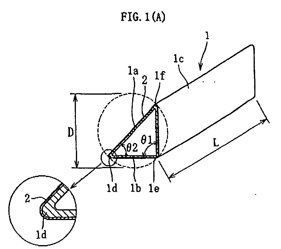
- a prism 1 according to the present invention which is a right-angle prism in the shape of a right-angled isosceles triangle made of transparent optical glass, such as BK-7, comprises prism surfaces 1a, 1b, and 1c which are subjected to light such as an optical signal, and corner portions 1d, 1e, and 1f rounded in cross section which connect the prism surfaces 1a, 1b, and 1c to one another.
- the surfaces of the corner portions 1d, 1e, and 1f are fire-polished surfaces, and the Ra value of the surface roughness thereof is 30nm.
- a compressive stress layer 2 having stress of approximately 3MPa is formed on each of the surfaces of the corner portions 1d, 1e, and 1f.
- the structure described above physically strengthens the corner portions 1d, 1e, and 1f.
- the Ra value of the surface roughness of each of the prism surfaces 1a, 1b, and 1c is 30nm, and the flatness thereof is better than a quarter of the wavelength ⁇ of incident light, so that the prism surfaces are able to transmit or reflect light without scattering.
- the prism surfaces 1b and 1c form an angle ⁇ 1 of 90 degrees ⁇ 15"
- the prism surfaces 1a and 1b form an angle of ⁇ 2 of 45 degrees ⁇ 15" with very high precision.
- the prism 1 is a small-sized prism, a side of which is 0.5mm and in which a diameter D of a circumscribed circle is 0.7mm.
- a length L parallel to the prism surfaces 1a, 1b, and 1c is 2mm, and the prism 1 takes a elongate shape so as to satisfy the relation of L ⁇ 1.5D/2 0.5 .
- the bending strength of the prism 1 is 120MPa, which increases by approximately 2.5 times as compared with the same-sized conventional prism manufactured by polishing.
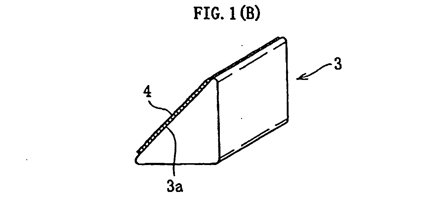
- FIG. 1(B) shows a prism 3 according to another embodiment.
- a filter film 4 which transmit light with a wavelength of 1310nm by equal to or more than 95%, and does not substantially transmit and totally reflects light with a wavelength of 1550nm is formed on a prism surface 3a of the prism 3, and the prism 3 is used as, for example, an optical switch and the like.
- FIG. 1(C) shows prisms 5 and 6 according to further another embodiment.
- a polarizing film 7 having the function of a beam splitter for processing P polarization and S polarization is formed between prism surfaces 5a and 6a opposed to each other, and the prisms 5 and 6 are used as, for example, an optical system for an optical head of an optical disk device.
- a glass base material 11 made of, for example, BK-7 being borosilicate optical glass, the minimum viscosity of which becomes 10 4 Pa ⁇ s when temperature is approximately 850 deg C, has surfaces 11a, 11b, and 11c which become prism surfaces after forming.
- the glass base material 11 takes the shape of a right-angled isosceles triangle the base of which is the surface 11a in cross section, and the length of the side of the surfaces 11b and 11c is approximately 10 to 70mm, and the surfaces 11b and 11c form an angle of 90 degrees ⁇ 15".
- the Ra value of the surface roughness of each of the surfaces 11a, 11b, and 11c, to be the prism surfaces of the prism after forming the glass base material 11, corresponds to #600 less than the Ra value corresponding to #170, which is about 2 ⁇ m, more specially, the Ra value of each of the surfaces 11a to 11c is 0.3 to 0.54 ⁇ m, for example, about 0.4 ⁇ m.
- FIG. 2(B) shows an apparatus for drawing and forming the glass base material 11.
- the drawing and forming apparatus forms a longer body 17 which is substantially similar to the glass base material 11 in shape, and has a dimension in a desired range.
- This drawing and forming apparatus essentially comprises a feeding means 12 having a grasp portion 12a for grasping the glass base material 11, a heating furnace 14 for heating the glass base material 11 to a predetermined temperature in which the minimum viscosity thereof becomes equal to or more than 10 4 Pa ⁇ s and less than 10 6 Pa ⁇ s, a drawing means 15 having a pair of rollers 15a and 15b for drawing and forming the lower portion of the glass base material 11, and a cutting means 16 for cutting the drawn glass.
- the heating furnace 14 is provided with a heater 14a for heating the glass base material 11 to a predetermined temperature in which the minimum viscosity thereof becomes equal to or more than 10 4 Pa ⁇ s and less than 10 6 Pa ⁇ s, a thermocouple 14b for measuring temperatures inside the furnace, and a power controller 14d which controls the output of the heater 14a with respect to a target temperature by means of inputting the electric signal of the thermocouple 14b to a temperature controller 14c.
- the power controller 14d makes the temperature stable in a predetermined range in which the minimum viscosity of the glass base material 11 becomes equal to or more than 10 4 Pa ⁇ s and less than 10 6 Pa ⁇ s .
- the glass base material 11, grasped by the grasp portion 12a of the feeding means 12, is fed into the heating furnace 14 at a constant speed.
- measuring the feeding speed of the glass base material 11 in drawing and forming, and operating the feeding means by inputting the signal of the feeding speed to a controller (not shown) make it possible to stably control the feeding speed of the glass base material 11 with high precision.
- the heating furnace 14 heats the glass base material 11 to approximately 800 deg C, at which the minimum viscosity thereof becomes 10 5 Pa ⁇ s. Since the electric signal of the thermocouple 14b for measuring the temperature in the furnace is inputted to the temperature controller 14c, the power controller 14d operates to increase the output of the heater 14a when the temperature in the furnace measured by the thermocouple 14b is lower than a target temperature, approximately 800 deg C, and hence, the temperature in the heating furnace 14 is stably controlled so that the minimum viscosity of the glass base material 11 becomes 10 5 Pa ⁇ s with precision.
- the power controller 14d operates to decrease the output of the heater 14a, and hence, the temperature in the heating furnace 14 is stably controlled so that the minimum viscosity of the glass base material 11 becomes 10 5 Pa ⁇ s with precision.
- a glass portion which is substantially solidified in a condition of being drawn downward from the glass base material 11 in the heating furnace 4 and being almost in predetermined dimension, is pinched and pressed by the pair of rollers 15a and 15b to make frictional force act enough, and then is drawn at a constant drawing speed which is several hundreds to several thousands times faster than the feeding speed of the glass base material 11.
- the cutting means 16 cuts the drawn glass to obtain the longer body 17 the shape of which is substantially similar to the glass base material 11.
- a precision cutting device cuts the precise longer body 17 so that, for example, the total length L thereof becomes 2mm, to manufacture the prism 1. At this time, if a plurality of the longer bodies 17 arranged in 2-diminsional or 3-dimensional are cut at the same time, operating efficiency increases.
- the heated glass base material 11 made of optical glass, is drawn and formed with low viscosity, it becomes possible to stably form the longer body 17 with high precision, so that the prism 1 is manufactured in a few processes.
- the prism is made of optical glass in the above embodiments, but may be made of ordinary glass for industrial use, or the like. When the prism needs heat resistance, transparent crystallized glass may be used.
- the prism is a right-angle prism in the above embodiments, but the present invention is not limited thereto.
- the present invention is applicable to prisms in various shapes, such as a prism in the shape of a triangle with an acute angle or an obtuse angle, a prism in the shape of a quadrilateral including a trapezoid and a diamond, a prism in the shape of the other polygons, a prism in the special shape a part of which has a curve, and the like.
Landscapes
- Physics & Mathematics (AREA)
- General Physics & Mathematics (AREA)
- Optics & Photonics (AREA)
- Chemical & Material Sciences (AREA)
- Engineering & Computer Science (AREA)
- Materials Engineering (AREA)
- Organic Chemistry (AREA)
- Optical Elements Other Than Lenses (AREA)
- Re-Forming, After-Treatment, Cutting And Transporting Of Glass Products (AREA)
Abstract
Description
Claims (6)
- A prism made of transparent glass comprising prism surfaces subjected to light, and corner portions adjacent to the prism surfaces,
wherein surfaces of the corner portions are fire-polished surfaces, and
wherein a compressive stress layer having stress of 0.1 to 10MPa is formed in the surface of the corner portion. - A prism according to claim 1, wherein a sectional area perpendicular to each of the prism surfaces is equal to or less than 100mm2.
- A prism according to claim 1 or 2, wherein the prism satisfies a relation of L ≧ 1.5D/20.5, where D represents a diameter of a circumscribed circle of a section perpendicular to the prism surfaces, and L represents a length of the prism in a direction parallel to the prism surfaces.
- A prism according to any one of claims 1 to 3, wherein an optical film is formed on the prism surface.
- A method for producing a prism, comprising the steps of:preparing a glass base material made of transparent glass, the glass base material having surfaces to be prism surfaces after forming, the Ra value of the surface roughness of the surface being less than the Ra value corresponding to #170, the glass base material having a dimensional ratio in a predetermined range with respect to the prism obtained after forming;grasping the glass base material with a grasp portion of feeding means, and feeding the glass base material into a heating furnace to heat the glass base material to a predetermined temperature so that a minimum viscosity of the glass base material becomes equal to or more than 104 and less than 106 Pa·s,drawing and forming a lower portion of the glass base material by drawing means, and then cutting the glass base material into a predetermined length to obtain a longer body having a substantially similar shape to that of the glass base material and a dimension in a desired range, and having prism surfaces with the Ra value of the surface roughness equal to or less than a quarter of the wavelength of incident light; andcutting the longer body into desired length.
- A method for producing a prism according to claim 5, wherein the prism surfaces of the longer body is polished.
Applications Claiming Priority (3)
| Application Number | Priority Date | Filing Date | Title |
|---|---|---|---|
| JP2002063571 | 2002-03-08 | ||
| JP2002063571 | 2002-03-08 | ||
| PCT/JP2003/002530 WO2003076983A1 (en) | 2002-03-08 | 2003-03-05 | Prism and method of producing the same |
Publications (2)
| Publication Number | Publication Date |
|---|---|
| EP1484622A1 true EP1484622A1 (en) | 2004-12-08 |
| EP1484622A4 EP1484622A4 (en) | 2012-02-22 |
Family
ID=27800194
Family Applications (1)
| Application Number | Title | Priority Date | Filing Date |
|---|---|---|---|
| EP03708475A Withdrawn EP1484622A4 (en) | 2002-03-08 | 2003-03-05 | Prism and method of producing the same |
Country Status (7)
| Country | Link |
|---|---|
| US (1) | US7075740B2 (en) |
| EP (1) | EP1484622A4 (en) |
| CN (1) | CN1294428C (en) |
| AU (1) | AU2003213365A1 (en) |
| CA (1) | CA2478641A1 (en) |
| TW (1) | TWI257922B (en) |
| WO (1) | WO2003076983A1 (en) |
Cited By (2)
| Publication number | Priority date | Publication date | Assignee | Title |
|---|---|---|---|---|
| US5782961A (en) * | 1994-03-22 | 1998-07-21 | Karlsson; Ernst Folke Jean | Method for the protective treatment of mineral material structures, treatment composition intended for performing of the method and use thereof |
| CN101514076B (en) * | 2009-03-31 | 2011-07-27 | 四川欧瑞特光电科技有限公司 | Cube-corner prism forming method, specialized triangular tool and V-shaped groove tool |
Families Citing this family (9)
| Publication number | Priority date | Publication date | Assignee | Title |
|---|---|---|---|---|
| JP4653809B2 (en) * | 2005-11-18 | 2011-03-16 | パナソニック株式会社 | Prism, imaging device and illumination device including the same, and prism manufacturing method |
| CN101382659B (en) * | 2007-09-07 | 2010-09-29 | 鸿富锦精密工业(深圳)有限公司 | A kind of total internal reflection prism system and its manufacturing method |
| CN101672938B (en) * | 2009-09-30 | 2011-04-13 | 嘉兴蓝特光学有限公司 | Molding processing method of roof prism |
| KR101681143B1 (en) * | 2010-07-19 | 2016-12-02 | 삼성디스플레이 주식회사 | Exposure apparatus and exposure method using the same |
| US8857220B2 (en) * | 2012-02-23 | 2014-10-14 | Corning Incorporated | Methods of making a stub lens element and assemblies using same for optical coherence tomography applications |
| CN106291787B (en) * | 2016-08-31 | 2018-09-18 | 成都恒达光学有限公司 | A kind of prism processing technology |
| CN108169997B (en) * | 2017-12-26 | 2020-12-22 | 武汉华星光电技术有限公司 | Optical compensation films, masks and exposure machines |
| CN113511804B (en) * | 2021-03-23 | 2023-05-12 | 常州第二电子仪器有限公司 | Coarse processing method of 45-degree right-angle prism |
| CN115872609B (en) * | 2022-12-23 | 2023-06-20 | 中山市光大光学仪器有限公司 | Irregular prism engraving and milling device capable of preventing edge breakage |
Family Cites Families (8)
| Publication number | Priority date | Publication date | Assignee | Title |
|---|---|---|---|---|
| US3879182A (en) * | 1974-02-04 | 1975-04-22 | American Optical Corp | Method of making minature prisms |
| US3989495A (en) * | 1975-07-10 | 1976-11-02 | American Optical Corporation | Method of making optical prisms |
| US5080706A (en) * | 1990-10-01 | 1992-01-14 | The United States Of America As Represented By The Department Of Energy | Method for fabrication of cylindrical microlenses of selected shape |
| EP0507000B1 (en) * | 1991-03-30 | 1996-04-03 | Shin-Etsu Quartz Co., Ltd. | Base body of reflecting mirror and method for preparing the same |
| JP3692512B2 (en) * | 1995-10-25 | 2005-09-07 | 日本電気硝子株式会社 | Crystalline glass stretch molding equipment |
| KR100752808B1 (en) * | 1999-11-10 | 2007-08-29 | 하마마츠 포토닉스 가부시키가이샤 | Manufacturing method of the optical lens |
| JP2001354441A (en) * | 2000-06-12 | 2001-12-25 | Nippon Sheet Glass Co Ltd | Method for manufacturing optical glass element and optical glass element manufactured by this manufacturing method |
| JP2002080245A (en) * | 2000-06-28 | 2002-03-19 | Canon Inc | Reflection type optical element and method of manufacturing the same |
-
2003
- 2003-03-05 CA CA002478641A patent/CA2478641A1/en not_active Abandoned
- 2003-03-05 WO PCT/JP2003/002530 patent/WO2003076983A1/en not_active Ceased
- 2003-03-05 US US10/507,086 patent/US7075740B2/en not_active Expired - Lifetime
- 2003-03-05 CN CNB038054981A patent/CN1294428C/en not_active Expired - Fee Related
- 2003-03-05 EP EP03708475A patent/EP1484622A4/en not_active Withdrawn
- 2003-03-05 AU AU2003213365A patent/AU2003213365A1/en not_active Abandoned
- 2003-03-06 TW TW092104767A patent/TWI257922B/en not_active IP Right Cessation
Cited By (2)
| Publication number | Priority date | Publication date | Assignee | Title |
|---|---|---|---|---|
| US5782961A (en) * | 1994-03-22 | 1998-07-21 | Karlsson; Ernst Folke Jean | Method for the protective treatment of mineral material structures, treatment composition intended for performing of the method and use thereof |
| CN101514076B (en) * | 2009-03-31 | 2011-07-27 | 四川欧瑞特光电科技有限公司 | Cube-corner prism forming method, specialized triangular tool and V-shaped groove tool |
Also Published As
| Publication number | Publication date |
|---|---|
| WO2003076983A1 (en) | 2003-09-18 |
| TWI257922B (en) | 2006-07-11 |
| AU2003213365A1 (en) | 2003-09-22 |
| CN1294428C (en) | 2007-01-10 |
| EP1484622A4 (en) | 2012-02-22 |
| TW200305544A (en) | 2003-11-01 |
| CA2478641A1 (en) | 2003-09-18 |
| US7075740B2 (en) | 2006-07-11 |
| CN1639591A (en) | 2005-07-13 |
| US20050122601A1 (en) | 2005-06-09 |
Similar Documents
| Publication | Publication Date | Title |
|---|---|---|
| US7616857B2 (en) | Optical fiber array substrate | |
| US7075740B2 (en) | Prism and method for producing the same | |
| JP2001026052A (en) | Method for transferring fine shape and method for manufacturing optical component | |
| CA2967365A1 (en) | A method of laser polishing a connectorized optical fiber and a connectorized optical fiber formed in accordance therewith | |
| US7003983B2 (en) | Method of manufacturing optical glass element, and optical glass element manufactured using the method | |
| US3989495A (en) | Method of making optical prisms | |
| CN117863006A (en) | Roof prism processing method and photoresist tool assembly | |
| JP2003329817A (en) | Prism and method for producing the same | |
| JP3973699B2 (en) | Optical fiber fixing member, optical fiber fixing member manufacturing method, optical fiber array, and optical fiber array manufacturing method | |
| JPH10245236A (en) | Preliminary glass molded product and production of member for fixing optical fiber with the same | |
| JP4106616B2 (en) | Manufacturing method of optical fiber array substrate | |
| JP2001166117A (en) | Method of producing glass optical elements | |
| US20080240186A1 (en) | Polygonal cross-section laser rod for low-cost flashlamp-pumped laser | |
| US20060260363A1 (en) | Method of manufacturing optical element | |
| CN116354591A (en) | A glass production process | |
| JP4058629B2 (en) | Manufacturing method of optical fiber array substrate | |
| JPH11194226A (en) | Member for optical fiber fixation, optical fiber array, and optical waveguide module | |
| JP4292522B2 (en) | Optical fiber array substrate | |
| JPH10236829A (en) | Production of glass formed article | |
| JPH02153832A (en) | Method for preparing end face of glass or glass fiber | |
| JPH06247725A (en) | Molding method of optical parts | |
| JP2002341172A (en) | Method of manufacturing optical fiber welded part reinforcing member | |
| JPH11129270A (en) | Manufacture of optical fiber fixing member | |
| JP3952136B2 (en) | Reinforcing member for optical fiber fusion part | |
| JPS61146723A (en) | Molding method of nonspherical surface lens |
Legal Events
| Date | Code | Title | Description |
|---|---|---|---|
| PUAI | Public reference made under article 153(3) epc to a published international application that has entered the european phase |
Free format text: ORIGINAL CODE: 0009012 |
|
| 17P | Request for examination filed |
Effective date: 20040906 |
|
| AK | Designated contracting states |
Kind code of ref document: A1 Designated state(s): AT BE BG CH CY CZ DE DK EE ES FI FR GB GR IE IT LI LU MC NL PT RO SE SI SK TR |
|
| AX | Request for extension of the european patent |
Extension state: AL LT LV MK |
|
| A4 | Supplementary search report drawn up and despatched |
Effective date: 20120123 |
|
| RIC1 | Information provided on ipc code assigned before grant |
Ipc: C03B 23/047 20060101ALI20120117BHEP Ipc: G02B 5/04 20060101AFI20120117BHEP |
|
| 17Q | First examination report despatched |
Effective date: 20120530 |
|
| STAA | Information on the status of an ep patent application or granted ep patent |
Free format text: STATUS: THE APPLICATION IS DEEMED TO BE WITHDRAWN |
|
| 18D | Application deemed to be withdrawn |
Effective date: 20121211 |