EP1484148A1 - UV cure resin molding method - Google Patents
UV cure resin molding method Download PDFInfo
- Publication number
- EP1484148A1 EP1484148A1 EP04076640A EP04076640A EP1484148A1 EP 1484148 A1 EP1484148 A1 EP 1484148A1 EP 04076640 A EP04076640 A EP 04076640A EP 04076640 A EP04076640 A EP 04076640A EP 1484148 A1 EP1484148 A1 EP 1484148A1
- Authority
- EP
- European Patent Office
- Prior art keywords
- mold
- cavity
- light
- curable material
- cure
- Prior art date
- Legal status (The legal status is an assumption and is not a legal conclusion. Google has not performed a legal analysis and makes no representation as to the accuracy of the status listed.)
- Granted
Links
- 238000000034 method Methods 0.000 title claims description 32
- 238000000465 moulding Methods 0.000 title description 16
- 239000011347 resin Substances 0.000 title description 5
- 229920005989 resin Polymers 0.000 title description 5
- 239000000463 material Substances 0.000 claims abstract description 56
- 238000004519 manufacturing process Methods 0.000 claims abstract description 15
- 239000007787 solid Substances 0.000 claims description 9
- 238000003848 UV Light-Curing Methods 0.000 claims description 6
- 238000003825 pressing Methods 0.000 claims description 3
- 230000005540 biological transmission Effects 0.000 claims description 2
- 230000007246 mechanism Effects 0.000 claims description 2
- 239000013307 optical fiber Substances 0.000 claims description 2
- 239000002537 cosmetic Substances 0.000 abstract 1
- 229920000642 polymer Polymers 0.000 description 12
- 238000005516 engineering process Methods 0.000 description 7
- 238000000576 coating method Methods 0.000 description 5
- 238000009472 formulation Methods 0.000 description 5
- 238000001746 injection moulding Methods 0.000 description 5
- 239000000203 mixture Substances 0.000 description 5
- 230000008569 process Effects 0.000 description 5
- 239000000758 substrate Substances 0.000 description 5
- 229910000831 Steel Inorganic materials 0.000 description 4
- 239000000853 adhesive Substances 0.000 description 4
- 230000001070 adhesive effect Effects 0.000 description 4
- 238000001816 cooling Methods 0.000 description 4
- 238000010438 heat treatment Methods 0.000 description 4
- 238000005286 illumination Methods 0.000 description 4
- 239000007788 liquid Substances 0.000 description 4
- 239000010959 steel Substances 0.000 description 4
- OXBLVCZKDOZZOJ-UHFFFAOYSA-N 2,3-Dihydrothiophene Chemical compound C1CC=CS1 OXBLVCZKDOZZOJ-UHFFFAOYSA-N 0.000 description 3
- 238000001723 curing Methods 0.000 description 3
- 238000005265 energy consumption Methods 0.000 description 3
- 238000012986 modification Methods 0.000 description 3
- 230000004048 modification Effects 0.000 description 3
- 239000004033 plastic Substances 0.000 description 3
- 229920003023 plastic Polymers 0.000 description 3
- 239000002904 solvent Substances 0.000 description 3
- KUDUQBURMYMBIJ-UHFFFAOYSA-N 2-prop-2-enoyloxyethyl prop-2-enoate Chemical compound C=CC(=O)OCCOC(=O)C=C KUDUQBURMYMBIJ-UHFFFAOYSA-N 0.000 description 2
- PPBRXRYQALVLMV-UHFFFAOYSA-N Styrene Chemical compound C=CC1=CC=CC=C1 PPBRXRYQALVLMV-UHFFFAOYSA-N 0.000 description 2
- 230000008030 elimination Effects 0.000 description 2
- 238000003379 elimination reaction Methods 0.000 description 2
- 238000001125 extrusion Methods 0.000 description 2
- 239000000835 fiber Substances 0.000 description 2
- 239000004615 ingredient Substances 0.000 description 2
- 239000012778 molding material Substances 0.000 description 2
- 239000002699 waste material Substances 0.000 description 2
- 239000002023 wood Substances 0.000 description 2
- OMIGHNLMNHATMP-UHFFFAOYSA-N 2-hydroxyethyl prop-2-enoate Chemical compound OCCOC(=O)C=C OMIGHNLMNHATMP-UHFFFAOYSA-N 0.000 description 1
- NIXOWILDQLNWCW-UHFFFAOYSA-M Acrylate Chemical compound [O-]C(=O)C=C NIXOWILDQLNWCW-UHFFFAOYSA-M 0.000 description 1
- 239000004593 Epoxy Substances 0.000 description 1
- WHNWPMSKXPGLAX-UHFFFAOYSA-N N-Vinyl-2-pyrrolidone Chemical compound C=CN1CCCC1=O WHNWPMSKXPGLAX-UHFFFAOYSA-N 0.000 description 1
- DAKWPKUUDNSNPN-UHFFFAOYSA-N Trimethylolpropane triacrylate Chemical compound C=CC(=O)OCC(CC)(COC(=O)C=C)COC(=O)C=C DAKWPKUUDNSNPN-UHFFFAOYSA-N 0.000 description 1
- IQYMRQZTDOLQHC-ZQTLJVIJSA-N [(1R,4S)-2-bicyclo[2.2.1]heptanyl] prop-2-enoate Chemical compound C1C[C@H]2C(OC(=O)C=C)C[C@@H]1C2 IQYMRQZTDOLQHC-ZQTLJVIJSA-N 0.000 description 1
- 150000001252 acrylic acid derivatives Chemical class 0.000 description 1
- 239000000654 additive Substances 0.000 description 1
- 239000013466 adhesive and sealant Substances 0.000 description 1
- 230000008901 benefit Effects 0.000 description 1
- 125000002091 cationic group Chemical group 0.000 description 1
- 239000000919 ceramic Substances 0.000 description 1
- 239000011248 coating agent Substances 0.000 description 1
- 238000013036 cure process Methods 0.000 description 1
- 230000003247 decreasing effect Effects 0.000 description 1
- 239000003085 diluting agent Substances 0.000 description 1
- 125000003700 epoxy group Chemical group 0.000 description 1
- 235000012438 extruded product Nutrition 0.000 description 1
- 239000004744 fabric Substances 0.000 description 1
- 239000000945 filler Substances 0.000 description 1
- 239000011521 glass Substances 0.000 description 1
- 238000002347 injection Methods 0.000 description 1
- 239000007924 injection Substances 0.000 description 1
- 239000000976 ink Substances 0.000 description 1
- 239000002184 metal Substances 0.000 description 1
- 239000000178 monomer Substances 0.000 description 1
- 230000003287 optical effect Effects 0.000 description 1
- -1 or newspaper Substances 0.000 description 1
- 239000003973 paint Substances 0.000 description 1
- 239000000123 paper Substances 0.000 description 1
- 239000002245 particle Substances 0.000 description 1
- 230000000704 physical effect Effects 0.000 description 1
- 239000000088 plastic resin Substances 0.000 description 1
- 229920000647 polyepoxide Polymers 0.000 description 1
- 229920000728 polyester Polymers 0.000 description 1
- 229920001223 polyethylene glycol Polymers 0.000 description 1
- 229920002635 polyurethane Polymers 0.000 description 1
- 239000004814 polyurethane Substances 0.000 description 1
- 230000005855 radiation Effects 0.000 description 1
- 239000000126 substance Substances 0.000 description 1
- 229940096522 trimethylolpropane triacrylate Drugs 0.000 description 1
- 239000002966 varnish Substances 0.000 description 1
Images

Classifications
-
- B—PERFORMING OPERATIONS; TRANSPORTING
- B29—WORKING OF PLASTICS; WORKING OF SUBSTANCES IN A PLASTIC STATE IN GENERAL
- B29C—SHAPING OR JOINING OF PLASTICS; SHAPING OF MATERIAL IN A PLASTIC STATE, NOT OTHERWISE PROVIDED FOR; AFTER-TREATMENT OF THE SHAPED PRODUCTS, e.g. REPAIRING
- B29C35/00—Heating, cooling or curing, e.g. crosslinking or vulcanising; Apparatus therefor
- B29C35/02—Heating or curing, e.g. crosslinking or vulcanizing during moulding, e.g. in a mould
- B29C35/08—Heating or curing, e.g. crosslinking or vulcanizing during moulding, e.g. in a mould by wave energy or particle radiation
- B29C35/0888—Heating or curing, e.g. crosslinking or vulcanizing during moulding, e.g. in a mould by wave energy or particle radiation using transparant moulds
-
- B—PERFORMING OPERATIONS; TRANSPORTING
- B29—WORKING OF PLASTICS; WORKING OF SUBSTANCES IN A PLASTIC STATE IN GENERAL
- B29C—SHAPING OR JOINING OF PLASTICS; SHAPING OF MATERIAL IN A PLASTIC STATE, NOT OTHERWISE PROVIDED FOR; AFTER-TREATMENT OF THE SHAPED PRODUCTS, e.g. REPAIRING
- B29C33/00—Moulds or cores; Details thereof or accessories therefor
- B29C33/34—Moulds or cores; Details thereof or accessories therefor movable, e.g. to or from the moulding station
- B29C33/36—Moulds or cores; Details thereof or accessories therefor movable, e.g. to or from the moulding station continuously movable in one direction, e.g. in a closed circuit
-
- B—PERFORMING OPERATIONS; TRANSPORTING
- B29—WORKING OF PLASTICS; WORKING OF SUBSTANCES IN A PLASTIC STATE IN GENERAL
- B29C—SHAPING OR JOINING OF PLASTICS; SHAPING OF MATERIAL IN A PLASTIC STATE, NOT OTHERWISE PROVIDED FOR; AFTER-TREATMENT OF THE SHAPED PRODUCTS, e.g. REPAIRING
- B29C35/00—Heating, cooling or curing, e.g. crosslinking or vulcanising; Apparatus therefor
- B29C35/02—Heating or curing, e.g. crosslinking or vulcanizing during moulding, e.g. in a mould
- B29C35/08—Heating or curing, e.g. crosslinking or vulcanizing during moulding, e.g. in a mould by wave energy or particle radiation
- B29C35/0805—Heating or curing, e.g. crosslinking or vulcanizing during moulding, e.g. in a mould by wave energy or particle radiation using electromagnetic radiation
-
- B—PERFORMING OPERATIONS; TRANSPORTING
- B29—WORKING OF PLASTICS; WORKING OF SUBSTANCES IN A PLASTIC STATE IN GENERAL
- B29C—SHAPING OR JOINING OF PLASTICS; SHAPING OF MATERIAL IN A PLASTIC STATE, NOT OTHERWISE PROVIDED FOR; AFTER-TREATMENT OF THE SHAPED PRODUCTS, e.g. REPAIRING
- B29C35/00—Heating, cooling or curing, e.g. crosslinking or vulcanising; Apparatus therefor
- B29C35/02—Heating or curing, e.g. crosslinking or vulcanizing during moulding, e.g. in a mould
- B29C35/08—Heating or curing, e.g. crosslinking or vulcanizing during moulding, e.g. in a mould by wave energy or particle radiation
- B29C35/10—Heating or curing, e.g. crosslinking or vulcanizing during moulding, e.g. in a mould by wave energy or particle radiation for articles of indefinite length
-
- B—PERFORMING OPERATIONS; TRANSPORTING
- B29—WORKING OF PLASTICS; WORKING OF SUBSTANCES IN A PLASTIC STATE IN GENERAL
- B29C—SHAPING OR JOINING OF PLASTICS; SHAPING OF MATERIAL IN A PLASTIC STATE, NOT OTHERWISE PROVIDED FOR; AFTER-TREATMENT OF THE SHAPED PRODUCTS, e.g. REPAIRING
- B29C33/00—Moulds or cores; Details thereof or accessories therefor
- B29C2033/0005—Moulds or cores; Details thereof or accessories therefor with transparent parts, e.g. permitting visual inspection of the interior of the cavity
-
- B—PERFORMING OPERATIONS; TRANSPORTING
- B29—WORKING OF PLASTICS; WORKING OF SUBSTANCES IN A PLASTIC STATE IN GENERAL
- B29C—SHAPING OR JOINING OF PLASTICS; SHAPING OF MATERIAL IN A PLASTIC STATE, NOT OTHERWISE PROVIDED FOR; AFTER-TREATMENT OF THE SHAPED PRODUCTS, e.g. REPAIRING
- B29C35/00—Heating, cooling or curing, e.g. crosslinking or vulcanising; Apparatus therefor
- B29C35/02—Heating or curing, e.g. crosslinking or vulcanizing during moulding, e.g. in a mould
- B29C35/08—Heating or curing, e.g. crosslinking or vulcanizing during moulding, e.g. in a mould by wave energy or particle radiation
- B29C35/0805—Heating or curing, e.g. crosslinking or vulcanizing during moulding, e.g. in a mould by wave energy or particle radiation using electromagnetic radiation
- B29C2035/0827—Heating or curing, e.g. crosslinking or vulcanizing during moulding, e.g. in a mould by wave energy or particle radiation using electromagnetic radiation using UV radiation
-
- B—PERFORMING OPERATIONS; TRANSPORTING
- B29—WORKING OF PLASTICS; WORKING OF SUBSTANCES IN A PLASTIC STATE IN GENERAL
- B29C—SHAPING OR JOINING OF PLASTICS; SHAPING OF MATERIAL IN A PLASTIC STATE, NOT OTHERWISE PROVIDED FOR; AFTER-TREATMENT OF THE SHAPED PRODUCTS, e.g. REPAIRING
- B29C48/00—Extrusion moulding, i.e. expressing the moulding material through a die or nozzle which imparts the desired form; Apparatus therefor
- B29C48/022—Extrusion moulding, i.e. expressing the moulding material through a die or nozzle which imparts the desired form; Apparatus therefor characterised by the choice of material
-
- B—PERFORMING OPERATIONS; TRANSPORTING
- B29—WORKING OF PLASTICS; WORKING OF SUBSTANCES IN A PLASTIC STATE IN GENERAL
- B29C—SHAPING OR JOINING OF PLASTICS; SHAPING OF MATERIAL IN A PLASTIC STATE, NOT OTHERWISE PROVIDED FOR; AFTER-TREATMENT OF THE SHAPED PRODUCTS, e.g. REPAIRING
- B29C48/00—Extrusion moulding, i.e. expressing the moulding material through a die or nozzle which imparts the desired form; Apparatus therefor
- B29C48/03—Extrusion moulding, i.e. expressing the moulding material through a die or nozzle which imparts the desired form; Apparatus therefor characterised by the shape of the extruded material at extrusion
- B29C48/07—Flat, e.g. panels
Definitions
- the present invention relates to a method for manufacturing plastic resin components. More specifically, this invention relates to a method of molding plastic resins using ultraviolet ("UV”) cure technology.
- UV ultraviolet
- UV cure technology is used in both industrial and decorative applications.
- the technology involves a photopolymerization process that fuses resin molecules together to form molecular chains.
- UV curing is widely used in paints, inks and varnishes.
- UV cure coatings are often used to provide scratch-resistance and durability to the surface of products such as digital versatile discs (DVDs), golf balls, and guitar bodies, providing a smooth, attractive appearance to these products.
- UV cure adhesives and sealants are also widely used. They provide quick bonding due to their ability to cure rapidly, in seconds, with a clear, colorless appearance.
- the viscosity of the UV cure adhesive can be varied depending upon the application. They provide a strong durable bond for a wide variety of substrates, including glass, plastics, wood, ceramics and paper.
- the UV cure process produces strong durable bonds in seconds without the use of solvents, providing an efficient and environmentally-friendly. Further, cationic adhesives that have been developed continue to cure after the light source is removed providing an even greater finished cure strength.
- UV curing systems have been used in coatings and other applications permitting UV light irradiation of coated surfaces
- UV curing systems have not been heretofore used in other applications, in particular, have not been known to be used in connection with cavity molding methods.
- UV cure resins have been used to form coatings and adhesives, they have not generally been used in molding applications.
- UV cure technology is an efficient means of molding materials as it involves low energy consumption. Productivity is improved as exposure to mere seconds of UV light initiates cure.
- UV cure technology is environmentally-friendly as it does not require use solvents. It does not require the heating and cooling or applying pressure to mold the material. This results in a minimal cavity space and increased gate size.
- molds may be made from a wider variety of substrates, including heat sensitive materials, and is not limited to high strength steels. Additionally, there is no shrinking, warping or occurrence of voids as in traditional molding processes. Therefore, molding of UV curable material is ideal for manufacturing articles or components of an aesthetic nature.
- a method of manufacturing molded articles in accordance with the invention comprises providing a mold or die at least substantially enclosing a cavity therein, filling the mold or die with a UV curable material, and exposing the UV curable material to a UV light source of a sufficient intensity and for a sufficient time to cure said UV curable material to a solid mass contained in said mold or die.
- the mold is formed of a plurality of mold segments that can be fitted together to form the mold and separated from each other to release a manufactured product from the mold.
- the UV curable material is exposed to the UV light source either through an opening in the top of the mold or through UV transparent ports, panels or portions of the mold.
- the entire mold may be UV transparent.
- the UV light may be directed at the UV curable material through one or more such ports.
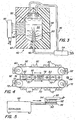
- FIG. 1 is a side elevation cross-sectional view of an embodiment of a mold for use in the method of the invention.
- FIG. 2 is a side elevation cross-sectional view of a second embodiment of a mold for use in the method of the invention.
- FIG. 3 is a side elevation cross-sectional view of a third embodiment of a mold for use in the method of the invention.
- FIG. 4 is a top plan view of a system in accordance with an embodiment of the method of the invention.
- FIG. 5 is a schematic view of an extension system in accordance with another embodiment of the method of the invention.
- the invention comprises the steps of: providing at least one mold of a desired shape or design having a cavity therein; filling the cavity with a UV curable material; and exposing the UV curable material to a UV light source of a sufficient intensity and for a sufficient time to cure the UV curable material to a solid mass contained in the cavity.
- the mold may be made of any material suitable for the application.
- the mold is filled with UV curable material by a precision dispensing system.
- the mold may have an interior coating to prevent sticking of the UV material, once cured to a solid mass, to the inside of the mold and to facilitate release of the solid mass from the mold.
- the UV curable material is limited in that it must transmit UV light, and therefore, cannot be opaque.
- the UV curable material may be pigmented or tinted.
- the UV curable material can be selected from a number of different UV curable polymer systems.
- a UV curable polymer system typically comprises 1-3% of a photoinitiators; 15-60% of reactive diluents, 25%-90% of an oligomer polymer; and 1-50% of additives and fillers.
- Polymers used in UV curable polymer systems can include polyurethanes, epoxies, polyesters and acrylates.
- polystyrene examples include N-vinylpyrrolidone, hydroxyethylacrylate, (poly)ethyleneglycol diacrylate, trimethylolpropanetriacrylate, norbornylacrylate, and styrene.
- Another suitable polymer system is the thiol-ene polymer system (also known as mercaptoesters).
- UV curable polymer systems include products from Master Bond, Inc., Hackensack, New Jersey, Tangent Industries, Winsted, Connecticut; Daicel Chemical Industries, Ltd., Sakai Osaka Japan, and Ctech LLC, New Hartford, Connecticut.
- a suitable thiol-ene polymer system is available from Ctech, LLC.
- the preferred UV curable liquid is a product that when cured will have good optical qualities, as this is typically indicative of the finish and look desired in the method of the invention.
- These products are typically cured at ambient temperatures, or at temperatures at or below 100 °C using a UV light source. Typical cure times range from 5 seconds to 5 minutes depending upon the wave length and intensity of the UV light and the thickness being cured.
- One preferred UV curable liquid is an acrylate formulation.
- One commercially available formulation that could be used in the invention is the Ctech 8166-4A formulation, which can be cured to a tack free surface with 5 minutes UV exposure at 100 °C.
- a preferred UV light source is a UV lamp providing a UV intensity of about 115 mW/cm2 at 365 nm.
- the UV light source desirably provides a broad range of wavelengths from 250 - 500 nm, which will cure materials much faster than if only the 365 nm radiation were delivered.
- Another preferred UV curable liquid is thiol-ene polymer system.
- One commercially available formulation that might be used in the invention is the Ctech Hard Dome Coat formulation, which preferably is cured at a lower intensity UV light in the range of 30 mW/cm2 with 5 minutes UV exposure at 100 °C.
- UV curable material may optionally be incorporated into the UV curable material.
- ingredients include, but are not limited to particles of cloth, wood, or newspaper, metal flakes, or the like. These ingredients may enhance the aesthetics and/or physical properties, such as strength, of the resulting molded article.
- the UV curable material may be tinted or pigmented to result in a translucent tinted article.
- the mold 10 comprises two mold segments 12 and 14 with an opening 16 at the top of mold 10. The segments are closed together to form a cavity 20 that is filled with an UV curable material 22. A UV light source 24 shutters light through the opening to cure the UV curable material. The mold segments 12 and 14 are then separated to release the molded article or component as discussed hereafter. Multiple molds may be exposed to the same UV light source at the same time, therefore allowing curing of multiple molded components at once.
- the mold 40 need not have an opening and UV light may be introduced into the cavity 50 through the walls of the mold 40 segments 42 and 44.
- the UV light can be provided by a UV light source 54 positioned to irradiate all of the cavity with UV light; or there can be multiple UV light sources 54 positioned to irradiate the cavity with UV light.
- a fiber optic or other light transmitting system 46 may be disposed in the mold itself to pass light into the cavity 50 of the mold 40 to illuminate the cavity 50. In the case of a larger mold, it may be desirable to have UV light is provided to the cavity by UV light transmission through a plurality of optical fibers 46 positioned to deliver UV light to a plurality of positions in the mold as shown in FIGS. 2 and 3.
- the mold 40 itself may be made, at least in part, of a UV transmissible material so light from UV lamp 55 on the exterior of the mold will be transmitted through the mold 40.
- the entire mold may be made of a UV transmissible material. Illumination of the UV material within the mold 40 is achieved in the various embodiments described herein.
- Mold 40 in FIG. 3 comprises a plurality of mold segments 42 and 44 which are positioned and collapsed together to render the desired cavity shape and/or configuration for injecting and curing the UV curable material, i.e., vertical or horizontal molding.
- At least one of the mold segments 42 is made of UV transmissible material to allow for illumination of the cavity; alternatively, the mold segment has a "window" 48 through which UV light is introduced.
- the cavity is filled with UV curable material 52, by suitable means such as injection and the like, and exposed to UV light source through the window 48 made of UV transmissible material.
- suitable means such as injection and the like
- UV light source through the window 48 made of UV transmissible material.
- an opening in the mold need not be provided to allow UV light illumination, the shape and design possibilities of the article or component increase and a cored or threaded article or component may easily be produced.
- simultaneous manufacturing of multiple molded articles is provided by two conveyors 70 and 80 positioned horizontally and parallel to each other are provided, moving in the same direction at a desired speed.
- Mold segments 72 and 82 are placed on both conveyors so that they travel down one side and back the other, aligned as pairs with segments on the opposite conveyor.
- the mold 74 travels beneath a filling station 76 which dispenses a UV curable material into the mold cavity.
- the cavity is then exposed to a UV light source 78 to cause curing.
- the cured article or component 84 is released from the cavity as the segments 72 and 82 separate from one another.
- the article may drop into bulk as finished product or be transferred to the next manufacturing step.
- a core 60 may also be included in the mold to form hollow articles and/or articles with shaped internal chambers as shown in FIG. 3.
- the core 60 must be made from a material capable of transmitting UV light so as to allow for cure of the UV curable material within the cavity.
- a UV transmittable core 60 allows UV light to transmit through the core 60 and cure potentially blocked or shaded areas of the mold.
- the core has a UV light source (including for example, a fiber optic output) embedded in the core to provide UV curing within the mold.
- the core 60 may also be a collapsible core that can be provided in the mold in an expanded or inflated state.
- a collapsible core could be made of a flexible polymeric material or a series of interfitting parts. After the article or component is cured, the core 60 is collapsed or deflated so that it is smaller than the entry point and can be removed from within the molded article.
- the collapsible core would be designed to form the desired internal geometry of the resulting article.
- An article, such as a bottle could be manufactured using this method with the advantage of the ability to decorate or stamp the bottle prior to removal of the collapsible core.
- Another aspect of the present invention is a method of forming an extruded product using a UV curable liquid.
- the extrusion method of the present method involves providing a die 90 of a desired configuration with a UV transmissible wall 92 (for example, a top plate), an entry aperture 94, and a discharge end 96.
- a UV curable material is injected into the die through the entry aperture using injection molding machine 98.
- the UV transmissible wall 92 is illuminated with UV light source 95 of sufficient intensity and for a sufficient period to cure the UV curable material.
- Pressure from the injection molding machine 98 is applied to the UV curable material causing it to exit the die as a solid mass through the die discharge end 96.
- a mechanism may be provided to remove the cured article from the discharge end.
- the present invention is expected to provide a method and system which will provide substantial improvements in manufacturing molded articles, including: (1) improved energy efficiency due to the elimination of requirements for mold heating and cooling of molds as is typically required of injection molding methods; (2) improved capital cost because the method allows zero pressure molding, thus eliminating the need for high strength steel molds, and allowing use of molds which are made of less expensive materials and which are less expensive to fabricate; (3) improved operating cost by reducing material waste and providing greater manufacturing flexibility.
- UV cure resins have been used to form coatings and adhesives, they have not generally been used in molding applications.
- UV cure technology is an efficient means of molding materials as it involves low energy consumption. Productivity is improved as exposure to mere seconds of UV light initiates cure.
- UV cure technology is environmentally-friendly as it does not require use solvents. It does not require the heating and cooling or applying pressure to mold the material. This results in a minimal cavity space and increased gate size.
- molds may be made from a wider variety of substrates, including heat sensitive materials, and is not limited to high strength steels. Additionally, there is no shrinking, warping or occurrence of voids as in traditional molding processes. Therefore, molding of UV curable material is ideal for manufacturing articles or components of an aesthetic nature.
Landscapes
- Health & Medical Sciences (AREA)
- Physics & Mathematics (AREA)
- Thermal Sciences (AREA)
- Toxicology (AREA)
- Oral & Maxillofacial Surgery (AREA)
- Mechanical Engineering (AREA)
- Engineering & Computer Science (AREA)
- Electromagnetism (AREA)
- Casting Or Compression Moulding Of Plastics Or The Like (AREA)
- Moulds For Moulding Plastics Or The Like (AREA)
- Heating, Cooling, Or Curing Plastics Or The Like In General (AREA)
- Injection Moulding Of Plastics Or The Like (AREA)
- Processing And Handling Of Plastics And Other Materials For Molding In General (AREA)
- Polymerisation Methods In General (AREA)
Abstract
Description
- The present invention relates to a method for manufacturing plastic resin components. More specifically, this invention relates to a method of molding plastic resins using ultraviolet ("UV") cure technology.
- Traditional molding methods involve injection molding and extrusion methods where a polymer is heated to a plastic state, then formed in a mold or die, then cooled to form a finished product. As such, the mold must be made from a substrate that is able to withstand these pressure and temperature changes. Often, molds are made of high strength steels and are expensive to produce. There remains a need for an efficient molding method with fewer production steps and reduced time for forming the finished product. The mold or die should be produced from a wider array of substrates to reduce costs and increase versatility of mold designs.
- UV cure technology is used in both industrial and decorative applications. The technology involves a photopolymerization process that fuses resin molecules together to form molecular chains. UV curing is widely used in paints, inks and varnishes. UV cure coatings are often used to provide scratch-resistance and durability to the surface of products such as digital versatile discs (DVDs), golf balls, and guitar bodies, providing a smooth, attractive appearance to these products. UV cure adhesives and sealants are also widely used. They provide quick bonding due to their ability to cure rapidly, in seconds, with a clear, colorless appearance. The viscosity of the UV cure adhesive can be varied depending upon the application. They provide a strong durable bond for a wide variety of substrates, including glass, plastics, wood, ceramics and paper. The UV cure process produces strong durable bonds in seconds without the use of solvents, providing an efficient and environmentally-friendly. Further, cationic adhesives that have been developed continue to cure after the light source is removed providing an even greater finished cure strength.
- While UV curing systems have been used in coatings and other applications permitting UV light irradiation of coated surfaces, UV curing systems have not been heretofore used in other applications, in particular, have not been known to be used in connection with cavity molding methods.
- It is an object of the invention to provide a method and system for manufacturing molded articles using UV curing systems. It is an object of the invention to provide substantial improvements in manufacturing molded articles, including elimination of heating and cooling of molds as is typically required of injection molding methods; decreasing energy consumption; reducing molding pressures; allowing use of lower cost mold materials; reducing material waste; and providing greater manufacturing flexibility.
- While UV cure resins have been used to form coatings and adhesives, they have not generally been used in molding applications. UV cure technology is an efficient means of molding materials as it involves low energy consumption. Productivity is improved as exposure to mere seconds of UV light initiates cure. Unlike other molding processes, UV cure technology is environmentally-friendly as it does not require use solvents. It does not require the heating and cooling or applying pressure to mold the material. This results in a minimal cavity space and increased gate size. As temperature is controlled, molds may be made from a wider variety of substrates, including heat sensitive materials, and is not limited to high strength steels. Additionally, there is no shrinking, warping or occurrence of voids as in traditional molding processes. Therefore, molding of UV curable material is ideal for manufacturing articles or components of an aesthetic nature.
- A method of manufacturing molded articles in accordance with the invention comprises providing a mold or die at least substantially enclosing a cavity therein, filling the mold or die with a UV curable material, and exposing the UV curable material to a UV light source of a sufficient intensity and for a sufficient time to cure said UV curable material to a solid mass contained in said mold or die. In preferred embodiments, the mold is formed of a plurality of mold segments that can be fitted together to form the mold and separated from each other to release a manufactured product from the mold. The UV curable material is exposed to the UV light source either through an opening in the top of the mold or through UV transparent ports, panels or portions of the mold. In one embodiment, the entire mold may be UV transparent. The UV light may be directed at the UV curable material through one or more such ports.
- Other objects, aspects and features of the present invention in addition to those mentioned above will be pointed out in or will be understood from the following detailed description provided in conjunction with the accompanying drawings.
- FIG. 1 is a side elevation cross-sectional view of an embodiment of a mold for use in the method of the invention.
- FIG. 2 is a side elevation cross-sectional view of a second embodiment of a mold for use in the method of the invention.
- FIG. 3 is a side elevation cross-sectional view of a third embodiment of a mold for use in the method of the invention.
- FIG. 4 is a top plan view of a system in accordance with an embodiment of the method of the invention.
- FIG. 5 is a schematic view of an extension system in accordance with another embodiment of the method of the invention.
- Generally, the invention comprises the steps of: providing at least one mold of a desired shape or design having a cavity therein; filling the cavity with a UV curable material; and exposing the UV curable material to a UV light source of a sufficient intensity and for a sufficient time to cure the UV curable material to a solid mass contained in the cavity.
- The mold may be made of any material suitable for the application. The mold is filled with UV curable material by a precision dispensing system. The mold may have an interior coating to prevent sticking of the UV material, once cured to a solid mass, to the inside of the mold and to facilitate release of the solid mass from the mold.
- The UV curable material is limited in that it must transmit UV light, and therefore, cannot be opaque. The UV curable material may be pigmented or tinted. The UV curable material can be selected from a number of different UV curable polymer systems. A UV curable polymer system typically comprises 1-3% of a photoinitiators; 15-60% of reactive diluents, 25%-90% of an oligomer polymer; and 1-50% of additives and fillers. Polymers used in UV curable polymer systems can include polyurethanes, epoxies, polyesters and acrylates. Specific commonly used monomers for the polymer include N-vinylpyrrolidone, hydroxyethylacrylate, (poly)ethyleneglycol diacrylate, trimethylolpropanetriacrylate, norbornylacrylate, and styrene. Another suitable polymer system is the thiol-ene polymer system (also known as mercaptoesters). Commercially available UV curable polymer systems include products from Master Bond, Inc., Hackensack, New Jersey, Tangent Industries, Winsted, Connecticut; Daicel Chemical Industries, Ltd., Sakai Osaka Japan, and Ctech LLC, New Hartford, Connecticut. A suitable thiol-ene polymer system is available from Ctech, LLC. The preferred UV curable liquid is a product that when cured will have good optical qualities, as this is typically indicative of the finish and look desired in the method of the invention. These products are typically cured at ambient temperatures, or at temperatures at or below 100 °C using a UV light source. Typical cure times range from 5 seconds to 5 minutes depending upon the wave length and intensity of the UV light and the thickness being cured.
- One preferred UV curable liquid is an acrylate formulation. One commercially available formulation that could be used in the invention is the Ctech 8166-4A formulation, which can be cured to a tack free surface with 5 minutes UV exposure at 100 °C.
- A preferred UV light source is a UV lamp providing a UV intensity of about 115 mW/cm2 at 365 nm. The UV light source desirably provides a broad range of wavelengths from 250 - 500 nm, which will cure materials much faster than if only the 365 nm radiation were delivered.
- Another preferred UV curable liquid is thiol-ene polymer system. One commercially available formulation that might be used in the invention is the Ctech Hard Dome Coat formulation, which preferably is cured at a lower intensity UV light in the range of 30 mW/cm2 with 5 minutes UV exposure at 100 °C.
- Additional components may optionally be incorporated into the UV curable material. These ingredients include, but are not limited to particles of cloth, wood, or newspaper, metal flakes, or the like. These ingredients may enhance the aesthetics and/or physical properties, such as strength, of the resulting molded article. The UV curable material may be tinted or pigmented to result in a translucent tinted article.
- The design of the mold and cavity must allow for direct illumination of the UV curable material by the UV light source. This may be achieved by various means, such as providing an opening in the upper end of the mold to direct UV light into the mold cavity, so long as the light entering from the opening exposes all of the interior surfaces of the mold. In one embodiment of the present invention shown in FIG. 1, the
mold 10 comprises twomold segments opening 16 at the top ofmold 10. The segments are closed together to form acavity 20 that is filled with an UVcurable material 22. AUV light source 24 shutters light through the opening to cure the UV curable material. Themold segments - In an alternative embodiment shown in FIGS. 2 and 3, the
mold 40 need not have an opening and UV light may be introduced into thecavity 50 through the walls of themold 40segments UV light source 54 positioned to irradiate all of the cavity with UV light; or there can be multipleUV light sources 54 positioned to irradiate the cavity with UV light. A fiber optic or otherlight transmitting system 46 may be disposed in the mold itself to pass light into thecavity 50 of themold 40 to illuminate thecavity 50. In the case of a larger mold, it may be desirable to have UV light is provided to the cavity by UV light transmission through a plurality ofoptical fibers 46 positioned to deliver UV light to a plurality of positions in the mold as shown in FIGS. 2 and 3. - As shown in FIG. 3, the
mold 40 itself may be made, at least in part, of a UV transmissible material so light fromUV lamp 55 on the exterior of the mold will be transmitted through themold 40. In one potential embodiment, the entire mold may be made of a UV transmissible material. Illumination of the UV material within themold 40 is achieved in the various embodiments described herein.Mold 40 in FIG. 3 comprises a plurality ofmold segments mold segments 42 is made of UV transmissible material to allow for illumination of the cavity; alternatively, the mold segment has a "window" 48 through which UV light is introduced. The cavity is filled with UVcurable material 52, by suitable means such as injection and the like, and exposed to UV light source through thewindow 48 made of UV transmissible material. In this embodiment, as an opening in the mold need not be provided to allow UV light illumination, the shape and design possibilities of the article or component increase and a cored or threaded article or component may easily be produced. - In another embodiment shown in FIG. 4, simultaneous manufacturing of multiple molded articles is provided by two
conveyors Mold segments segment 72 travels down oneconveyor 70, it interlocks with asegment 82 on the otherparallel conveyor 80, forming amold 74 having a cavity. Themold 74 travels beneath a fillingstation 76 which dispenses a UV curable material into the mold cavity. As themold 74 continues to travel along the conveyor belt, the cavity is then exposed to aUV light source 78 to cause curing. As the mold continues to the end of the conveyors, the cured article or component 84 is released from the cavity as thesegments - In any of the previously discussed embodiments, a
core 60 may also be included in the mold to form hollow articles and/or articles with shaped internal chambers as shown in FIG. 3. In such instances, the core 60 must be made from a material capable of transmitting UV light so as to allow for cure of the UV curable material within the cavity. A UVtransmittable core 60 allows UV light to transmit through thecore 60 and cure potentially blocked or shaded areas of the mold. In one potential embodiment, the core has a UV light source (including for example, a fiber optic output) embedded in the core to provide UV curing within the mold. - The core 60 may also be a collapsible core that can be provided in the mold in an expanded or inflated state. Such a collapsible core could be made of a flexible polymeric material or a series of interfitting parts. After the article or component is cured, the
core 60 is collapsed or deflated so that it is smaller than the entry point and can be removed from within the molded article. The collapsible core would be designed to form the desired internal geometry of the resulting article. An article, such as a bottle, could be manufactured using this method with the advantage of the ability to decorate or stamp the bottle prior to removal of the collapsible core. - Referring now to FIG. 5, Another aspect of the present invention is a method of forming an extruded product using a UV curable liquid. The extrusion method of the present method involves providing a
die 90 of a desired configuration with a UV transmissible wall 92 (for example, a top plate), anentry aperture 94, and adischarge end 96. A UV curable material is injected into the die through the entry aperture usinginjection molding machine 98. The UVtransmissible wall 92 is illuminated withUV light source 95 of sufficient intensity and for a sufficient period to cure the UV curable material. Pressure from theinjection molding machine 98 is applied to the UV curable material causing it to exit the die as a solid mass through thedie discharge end 96. Optionally, a mechanism may be provided to remove the cured article from the discharge end. - The present invention is expected to provide a method and system which will provide substantial improvements in manufacturing molded articles, including: (1) improved energy efficiency due to the elimination of requirements for mold heating and cooling of molds as is typically required of injection molding methods; (2) improved capital cost because the method allows zero pressure molding, thus eliminating the need for high strength steel molds, and allowing use of molds which are made of less expensive materials and which are less expensive to fabricate; (3) improved operating cost by reducing material waste and providing greater manufacturing flexibility.
- While UV cure resins have been used to form coatings and adhesives, they have not generally been used in molding applications. UV cure technology is an efficient means of molding materials as it involves low energy consumption. Productivity is improved as exposure to mere seconds of UV light initiates cure. Unlike other molding processes, UV cure technology is environmentally-friendly as it does not require use solvents. It does not require the heating and cooling or applying pressure to mold the material. This results in a minimal cavity space and increased gate size. As temperature is controlled, molds may be made from a wider variety of substrates, including heat sensitive materials, and is not limited to high strength steels. Additionally, there is no shrinking, warping or occurrence of voids as in traditional molding processes. Therefore, molding of UV curable material is ideal for manufacturing articles or components of an aesthetic nature.
- It is to be appreciated that the foregoing is illustrative and not limiting of the invention, and that various changes and modifications to the preferred embodiments described above will be apparent to those skilled in the art. Such changes and modifications can be made without departing from the spirit and scope of the present invention, and it is therefore intended that such changes and modifications be covered by the following claims.
Claims (11)
- A method of manufacturing a molded article, comprising the steps of:providing a mold (10, 40) at least substantially enclosing a cavity (20, 50) therein;filling the cavity with a UV curable material (22, 52); andexposing the UV curable material (22, 52) to UV light of a sufficient intensity and for a sufficient time to cure the UV curable material to a solid mass contained in the cavity.
- The method of claim 1, wherein at least a portion of the mold (10, 40) comprises a UV transmissible material.
- The method of claim 1 or claim 2, wherein the mold (10, 40) comprises a plurality of mold segments (12, 14, 42, 44) which fit together to define a cavity (20, 50).
- The method of any one of claims 1 to 3, wherein the UV light is provided by one or more UV light sources (24) positioned to irradiate all of the cavity (20, 50) with UV light.
- The method of claim 4, wherein the UV light is provided to the cavity by UV light transmission through one or more optical fibers (46).
- The method of any one of claims 3 to 5, wherein the mold segments (12, 14, 42, 44) are first fitted together to define a cavity (20, 50),the cavity (20, 50) is then filled with UV curable material (22, 52),the UV curable material (22, 52) is then exposed to UV light,and thereafter the mold segments (12, 14, 42, 44) are separated to release a solid mass from the cavity.
- The method of any one of claims 3 to 6, wherein the mold segments (72, 82) are mounted to a conveying system moving said mold segments (72, 82) from a mold filling station to a UV curing zone to a mold unloading station.
- The method of any one of claims 1 to 7, wherein the mold has a core disposed within the cavity.
- The method of claim 8, wherein the core is formed of a UV transmittable material.
- A method of manufacturing an extruded article, comprising the steps of:providing a die (90) having a UV transmissible wall (92), an entry aperture (94), and a discharge end (96);injecting a UV curable material into the die (90) through the entry aperture (94);illuminating the UV transmissible wall (92) with UV light;and applying pressure to the UV curable material causing it to exit the die (90) as a solid mass through the discharge end (96).
- The method of claim 10, further providing a mechanism to remove the solid mass from the discharge end (96) .
Priority Applications (1)
| Application Number | Priority Date | Filing Date | Title |
|---|---|---|---|
| PL04076640T PL1484148T3 (en) | 2003-06-06 | 2004-06-04 | UV cure resin molding method |
Applications Claiming Priority (2)
| Application Number | Priority Date | Filing Date | Title |
|---|---|---|---|
| US456021 | 1999-12-03 | ||
| US10/456,021 US20040245677A1 (en) | 2003-06-06 | 2003-06-06 | UV cure resin molding method |
Publications (2)
| Publication Number | Publication Date |
|---|---|
| EP1484148A1 true EP1484148A1 (en) | 2004-12-08 |
| EP1484148B1 EP1484148B1 (en) | 2007-05-30 |
Family
ID=33159573
Family Applications (1)
| Application Number | Title | Priority Date | Filing Date |
|---|---|---|---|
| EP04076640A Expired - Lifetime EP1484148B1 (en) | 2003-06-06 | 2004-06-04 | UV cure resin molding method |
Country Status (5)
| Country | Link |
|---|---|
| US (1) | US20040245677A1 (en) |
| EP (1) | EP1484148B1 (en) |
| AT (1) | ATE363368T1 (en) |
| DE (1) | DE602004006668T2 (en) |
| PL (1) | PL1484148T3 (en) |
Cited By (9)
| Publication number | Priority date | Publication date | Assignee | Title |
|---|---|---|---|---|
| WO2011155896A1 (en) * | 2010-06-08 | 2011-12-15 | Kungsörs Plast AB | A uv curing method and an assembly therefor |
| CN104640682A (en) * | 2012-08-14 | 2015-05-20 | 美国圣戈班性能塑料公司 | Apparatus and method for making a silicone article |
| US9982809B2 (en) | 2015-12-30 | 2018-05-29 | Saint-Gobain Performance Plastics Corporation | Composite tubing and method for making and using same |
| WO2018200363A3 (en) * | 2017-04-24 | 2019-11-07 | Nike Innovate C.V. | Transparent tooling mold and process for uv radiation curable rubber |
| US10779609B2 (en) | 2017-04-24 | 2020-09-22 | Nike, Inc. | Apparel and sporting equipment with an UV radiation curable material and method of manufacturing thereof |
| US11058180B2 (en) | 2016-06-16 | 2021-07-13 | Adidas Ag | UV curable lattice microstructure for footwear |
| US11122847B2 (en) | 2017-04-24 | 2021-09-21 | Nike, Inc. | Article with UV radiation curable material adhered to textile and method of making the same |
| US11136475B2 (en) | 2017-04-24 | 2021-10-05 | Nike, Inc. | Articles and components with UV radiation curable elastomeric materials and methods of making the same |
| DE102021205057A1 (en) | 2021-05-18 | 2022-11-24 | Leoni Bordnetz-Systeme Gmbh | Process for producing a vehicle electrical system element and vehicle electrical system element |
Families Citing this family (14)
| Publication number | Priority date | Publication date | Assignee | Title |
|---|---|---|---|---|
| US7479247B2 (en) * | 2005-05-12 | 2009-01-20 | Victor Joyner | Method and apparatus for creating sacrificial patterns and cast parts |
| JP4677857B2 (en) * | 2005-08-23 | 2011-04-27 | ヤマハ株式会社 | Musical instrument member or musical instrument and method for producing the same |
| CN101138872B (en) * | 2006-09-08 | 2010-06-16 | 东芝机械株式会社 | Mold for injection molding apparatus |
| GB0624562D0 (en) * | 2006-12-08 | 2007-01-17 | Airbus Uk Ltd | Self Curing Injection Nozzle |
| JP5349403B2 (en) * | 2010-05-17 | 2013-11-20 | テクノポリマー株式会社 | Light irradiation molding apparatus and method |
| DE102010034386A1 (en) * | 2010-08-13 | 2012-02-16 | Thomas Gmbh + Co. Technik + Innovation Kg | Method for producing and monitoring an article formed at least partially from plastic and a component |
| AT13189U1 (en) * | 2012-06-04 | 2013-08-15 | Elast Kunststoffverarbeitungs Gmbh Und Co Keg | Process and device for processing liquid silicone compositions in injection molding machine and injection molding machine |
| KR20160051874A (en) * | 2013-09-27 | 2016-05-11 | 생-고뱅 퍼포먼스 플라스틱스 코포레이션 | Apparatus and method for making an article |
| US11167310B2 (en) * | 2015-05-13 | 2021-11-09 | The Boeing Company | Sealing assembly for forming sealant coating on a fastener, the sealing assembly comprising a light generator and a forming cup associated with the light generator |
| SG10201911612PA (en) * | 2015-08-31 | 2020-02-27 | Agency Science Tech & Res | Method and system for forming a masking layer |
| US10016661B2 (en) * | 2016-04-06 | 2018-07-10 | Acushnet Company | Methods for making golf ball components using three-dimensional additive manufacturing systems |
| DE102017100353A1 (en) * | 2017-01-10 | 2018-07-12 | Vogel Moulds And Machines Ag | Apparatus and process for the production of plastic moldings from a mixture of several components |
| TWI843361B (en) * | 2021-12-31 | 2024-05-21 | 大陸商富聯裕展科技(深圳)有限公司 | Molding die, method of manufacturing the molding die, moulding apparatus, terminal, and bonding method of product |
| CN119519311A (en) * | 2024-11-12 | 2025-02-25 | 安徽致钲电驱动技术有限公司 | Stator winding potting tool |
Citations (8)
| Publication number | Priority date | Publication date | Assignee | Title |
|---|---|---|---|---|
| US3102303A (en) * | 1958-12-18 | 1963-09-03 | Western Plastics Corp | Apparatus for irradiation of plastics |
| JPS59215838A (en) * | 1983-05-24 | 1984-12-05 | Mitsubishi Electric Corp | Molding apparatus |
| EP0600106A1 (en) * | 1991-04-16 | 1994-06-08 | The C.A. Lawton Company | Mat forming process and apparatus |
| DE19705303A1 (en) * | 1996-02-16 | 1998-01-22 | Karlsruhe Forschzent | Production of small and micro-parts |
| US5885514A (en) * | 1996-12-09 | 1999-03-23 | Dana Corporation | Ambient UVL-curable elastomer mold apparatus |
| US5916509A (en) * | 1997-02-07 | 1999-06-29 | Durhman; Paul P. | Actinic irradiation and curing of plastic composites within a material forming die |
| US20020056930A1 (en) * | 2000-11-10 | 2002-05-16 | Kazuyuki Matsumoto | Method and apparatus for manufacturing a lens sheet |
| US20020185761A1 (en) * | 2001-02-20 | 2002-12-12 | Lattis Matthew C. | Method of entering prescription information |
Family Cites Families (9)
| Publication number | Priority date | Publication date | Assignee | Title |
|---|---|---|---|---|
| US185761A (en) * | 1876-12-26 | Improvement in locks for doors | ||
| US56930A (en) * | 1866-08-07 | Improvement in traveling-bag frames | ||
| US4859394A (en) * | 1985-11-04 | 1989-08-22 | Thomson Saginaw Ball Screw Co., Inc. | Method of molding a one piece plastic ball nut |
| US5183597A (en) * | 1989-02-10 | 1993-02-02 | Minnesota Mining And Manufacturing Company | Method of molding microstructure bearing composite plastic articles |
| EP0469384B1 (en) * | 1990-08-01 | 1995-03-15 | Siemens Aktiengesellschaft | Radiation curable resin composition |
| US5403179A (en) * | 1993-10-29 | 1995-04-04 | Ramsey; William C. | Collapsible mold core assembly |
| US5746967A (en) * | 1995-06-26 | 1998-05-05 | Fox Lite, Inc. | Method of curing thermoset resin with visible light |
| DK1116964T3 (en) * | 1995-07-29 | 2004-06-01 | Sanyo Chemical Ind Ltd | UV-curing resin mass for Fresnel lenses, Fresnel lenses and a rear projection screen |
| AU2001238306A1 (en) * | 2000-03-31 | 2001-10-15 | Bausch And Lomb Incorporated | Method and device to control polymerization |
-
2003
- 2003-06-06 US US10/456,021 patent/US20040245677A1/en not_active Abandoned
-
2004
- 2004-06-04 PL PL04076640T patent/PL1484148T3/en unknown
- 2004-06-04 DE DE602004006668T patent/DE602004006668T2/en not_active Expired - Fee Related
- 2004-06-04 AT AT04076640T patent/ATE363368T1/en not_active IP Right Cessation
- 2004-06-04 EP EP04076640A patent/EP1484148B1/en not_active Expired - Lifetime
Patent Citations (8)
| Publication number | Priority date | Publication date | Assignee | Title |
|---|---|---|---|---|
| US3102303A (en) * | 1958-12-18 | 1963-09-03 | Western Plastics Corp | Apparatus for irradiation of plastics |
| JPS59215838A (en) * | 1983-05-24 | 1984-12-05 | Mitsubishi Electric Corp | Molding apparatus |
| EP0600106A1 (en) * | 1991-04-16 | 1994-06-08 | The C.A. Lawton Company | Mat forming process and apparatus |
| DE19705303A1 (en) * | 1996-02-16 | 1998-01-22 | Karlsruhe Forschzent | Production of small and micro-parts |
| US5885514A (en) * | 1996-12-09 | 1999-03-23 | Dana Corporation | Ambient UVL-curable elastomer mold apparatus |
| US5916509A (en) * | 1997-02-07 | 1999-06-29 | Durhman; Paul P. | Actinic irradiation and curing of plastic composites within a material forming die |
| US20020056930A1 (en) * | 2000-11-10 | 2002-05-16 | Kazuyuki Matsumoto | Method and apparatus for manufacturing a lens sheet |
| US20020185761A1 (en) * | 2001-02-20 | 2002-12-12 | Lattis Matthew C. | Method of entering prescription information |
Non-Patent Citations (1)
| Title |
|---|
| PATENT ABSTRACTS OF JAPAN vol. 0090, no. 87 (M - 372) 17 April 1985 (1985-04-17) * |
Cited By (15)
| Publication number | Priority date | Publication date | Assignee | Title |
|---|---|---|---|---|
| US9643344B2 (en) | 2010-06-08 | 2017-05-09 | Kungsörs Plast AB | UV curing method and an assembly therefor |
| WO2011155896A1 (en) * | 2010-06-08 | 2011-12-15 | Kungsörs Plast AB | A uv curing method and an assembly therefor |
| CN104640682A (en) * | 2012-08-14 | 2015-05-20 | 美国圣戈班性能塑料公司 | Apparatus and method for making a silicone article |
| EP2885118A4 (en) * | 2012-08-14 | 2016-04-13 | Saint Gobain Performance Plast | APPARATUS AND METHOD FOR MANUFACTURING SILICONE ARTICLE |
| CN104640682B (en) * | 2012-08-14 | 2018-06-08 | 美国圣戈班性能塑料公司 | It is used to prepare the device and method of organosilicon product |
| US9982809B2 (en) | 2015-12-30 | 2018-05-29 | Saint-Gobain Performance Plastics Corporation | Composite tubing and method for making and using same |
| US11058180B2 (en) | 2016-06-16 | 2021-07-13 | Adidas Ag | UV curable lattice microstructure for footwear |
| US12004593B2 (en) | 2016-06-16 | 2024-06-11 | Adidas Ag | UV curable lattice microstructure for footwear |
| WO2018200363A3 (en) * | 2017-04-24 | 2019-11-07 | Nike Innovate C.V. | Transparent tooling mold and process for uv radiation curable rubber |
| US11122847B2 (en) | 2017-04-24 | 2021-09-21 | Nike, Inc. | Article with UV radiation curable material adhered to textile and method of making the same |
| US11136475B2 (en) | 2017-04-24 | 2021-10-05 | Nike, Inc. | Articles and components with UV radiation curable elastomeric materials and methods of making the same |
| US11673294B2 (en) | 2017-04-24 | 2023-06-13 | Nike, Inc. | Transparent tooling for UV radiation curable rubber |
| US10779609B2 (en) | 2017-04-24 | 2020-09-22 | Nike, Inc. | Apparel and sporting equipment with an UV radiation curable material and method of manufacturing thereof |
| US12030225B2 (en) | 2017-04-24 | 2024-07-09 | Nike, Inc. | Transparent tooling for UV radiation curable rubber |
| DE102021205057A1 (en) | 2021-05-18 | 2022-11-24 | Leoni Bordnetz-Systeme Gmbh | Process for producing a vehicle electrical system element and vehicle electrical system element |
Also Published As
| Publication number | Publication date |
|---|---|
| EP1484148B1 (en) | 2007-05-30 |
| ATE363368T1 (en) | 2007-06-15 |
| DE602004006668T2 (en) | 2008-01-31 |
| US20040245677A1 (en) | 2004-12-09 |
| PL1484148T3 (en) | 2008-03-31 |
| DE602004006668D1 (en) | 2007-07-12 |
Similar Documents
| Publication | Publication Date | Title |
|---|---|---|
| EP1484148B1 (en) | UV cure resin molding method | |
| US7025458B2 (en) | Process to mold a plastic optical article with integrated hard coating | |
| JP5071332B2 (en) | Decorative sheet for insert molding and decorative resin molded product | |
| EP2133201B1 (en) | Transfer decorative sheet and process for producing decorated molded product | |
| EP2596936B1 (en) | Mold and method for producing shaped articles from a UV-curable composition | |
| AU758276B2 (en) | Illumination device and method for making the same | |
| CA2489419A1 (en) | Methods for the production of tinted contact lenses | |
| JP5332258B2 (en) | Resin composition and decorative sheet using the resin composition | |
| ATE305847T1 (en) | METHOD FOR PRODUCING HEAVY DUTY COMPOSITE PARTS | |
| JPH0217973A (en) | Making of resin molded product provided with sweep resistant clad working | |
| JPH01146711A (en) | Manufacture of plastic molded form having scratch-resistant coating | |
| EP1270189A3 (en) | Ocular lens and process for its production | |
| CN103878996A (en) | Production device and production process of side-tilting polygonal crystal micro-structure retro-reflection material | |
| JP2003145573A (en) | Insert molding molded article and color ink therefor | |
| JP5228448B2 (en) | Decorative sheet, decorative resin molded product manufacturing method, and decorative resin molded product | |
| US20070184207A1 (en) | Method of molding decorative elements for consumer packaging | |
| IT8122447A1 (en) | SYNTHETIC RESIN MOLDED PRODUCT AND PROCEDURES FOR ITS PREPARATION | |
| WO1996007525A1 (en) | A method of producing a scratch resistant coating on a plastics substrate | |
| JP5012434B2 (en) | Decorative sheet, decorative resin molded product manufacturing method, and decorative resin molded product | |
| KR100840151B1 (en) | Apparatus for manufacturing retroreflective film and method for manufacturing same | |
| JP5527373B2 (en) | Decorative sheet for insert molding and decorative resin molded product | |
| NL8501897A (en) | Mfr. of injection moulded parts with scratch resistant surface | |
| JPH0584769A (en) | Production of injection molded product | |
| IT202000014725A1 (en) | Composition of photo-polymerizable resins, manufacturing method of an article using the same and article thus obtained | |
| JPH04166311A (en) | Manufacture of molded object |
Legal Events
| Date | Code | Title | Description |
|---|---|---|---|
| PUAI | Public reference made under article 153(3) epc to a published international application that has entered the european phase |
Free format text: ORIGINAL CODE: 0009012 |
|
| AK | Designated contracting states |
Kind code of ref document: A1 Designated state(s): AT BE BG CH CY CZ DE DK EE ES FI FR GB GR HU IE IT LI LU MC NL PL PT RO SE SI SK TR |
|
| AX | Request for extension of the european patent |
Extension state: AL HR LT LV MK |
|
| 17P | Request for examination filed |
Effective date: 20050427 |
|
| AKX | Designation fees paid |
Designated state(s): AT BE BG CH CY CZ DE DK EE ES FI FR GB GR HU IE IT LI LU MC NL PL PT RO SE SI SK TR |
|
| GRAP | Despatch of communication of intention to grant a patent |
Free format text: ORIGINAL CODE: EPIDOSNIGR1 |
|
| GRAS | Grant fee paid |
Free format text: ORIGINAL CODE: EPIDOSNIGR3 |
|
| GRAA | (expected) grant |
Free format text: ORIGINAL CODE: 0009210 |
|
| AK | Designated contracting states |
Kind code of ref document: B1 Designated state(s): AT BE BG CH CY CZ DE DK EE ES FI FR GB GR HU IE IT LI LU MC NL PL PT RO SE SI SK TR |
|
| PG25 | Lapsed in a contracting state [announced via postgrant information from national office to epo] |
Ref country code: CH Free format text: LAPSE BECAUSE OF FAILURE TO SUBMIT A TRANSLATION OF THE DESCRIPTION OR TO PAY THE FEE WITHIN THE PRESCRIBED TIME-LIMIT Effective date: 20070530 Ref country code: FI Free format text: LAPSE BECAUSE OF FAILURE TO SUBMIT A TRANSLATION OF THE DESCRIPTION OR TO PAY THE FEE WITHIN THE PRESCRIBED TIME-LIMIT Effective date: 20070530 Ref country code: LI Free format text: LAPSE BECAUSE OF FAILURE TO SUBMIT A TRANSLATION OF THE DESCRIPTION OR TO PAY THE FEE WITHIN THE PRESCRIBED TIME-LIMIT Effective date: 20070530 |
|
| REG | Reference to a national code |
Ref country code: GB Ref legal event code: FG4D |
|
| REG | Reference to a national code |
Ref country code: CH Ref legal event code: EP |
|
| REG | Reference to a national code |
Ref country code: IE Ref legal event code: FG4D |
|
| REF | Corresponds to: |
Ref document number: 602004006668 Country of ref document: DE Date of ref document: 20070712 Kind code of ref document: P |
|
| PG25 | Lapsed in a contracting state [announced via postgrant information from national office to epo] |
Ref country code: SE Free format text: LAPSE BECAUSE OF FAILURE TO SUBMIT A TRANSLATION OF THE DESCRIPTION OR TO PAY THE FEE WITHIN THE PRESCRIBED TIME-LIMIT Effective date: 20070830 |
|
| PG25 | Lapsed in a contracting state [announced via postgrant information from national office to epo] |
Ref country code: ES Free format text: LAPSE BECAUSE OF FAILURE TO SUBMIT A TRANSLATION OF THE DESCRIPTION OR TO PAY THE FEE WITHIN THE PRESCRIBED TIME-LIMIT Effective date: 20070910 |
|
| ET | Fr: translation filed | ||
| PG25 | Lapsed in a contracting state [announced via postgrant information from national office to epo] |
Ref country code: AT Free format text: LAPSE BECAUSE OF FAILURE TO SUBMIT A TRANSLATION OF THE DESCRIPTION OR TO PAY THE FEE WITHIN THE PRESCRIBED TIME-LIMIT Effective date: 20070530 |
|
| NLV1 | Nl: lapsed or annulled due to failure to fulfill the requirements of art. 29p and 29m of the patents act | ||
| REG | Reference to a national code |
Ref country code: CH Ref legal event code: PL |
|
| PG25 | Lapsed in a contracting state [announced via postgrant information from national office to epo] |
Ref country code: BE Free format text: LAPSE BECAUSE OF FAILURE TO SUBMIT A TRANSLATION OF THE DESCRIPTION OR TO PAY THE FEE WITHIN THE PRESCRIBED TIME-LIMIT Effective date: 20070530 |
|
| PG25 | Lapsed in a contracting state [announced via postgrant information from national office to epo] |
Ref country code: SI Free format text: LAPSE BECAUSE OF FAILURE TO SUBMIT A TRANSLATION OF THE DESCRIPTION OR TO PAY THE FEE WITHIN THE PRESCRIBED TIME-LIMIT Effective date: 20070530 Ref country code: MC Free format text: LAPSE BECAUSE OF NON-PAYMENT OF DUE FEES Effective date: 20070630 Ref country code: DK Free format text: LAPSE BECAUSE OF FAILURE TO SUBMIT A TRANSLATION OF THE DESCRIPTION OR TO PAY THE FEE WITHIN THE PRESCRIBED TIME-LIMIT Effective date: 20070530 Ref country code: BG Free format text: LAPSE BECAUSE OF FAILURE TO SUBMIT A TRANSLATION OF THE DESCRIPTION OR TO PAY THE FEE WITHIN THE PRESCRIBED TIME-LIMIT Effective date: 20070830 Ref country code: PT Free format text: LAPSE BECAUSE OF FAILURE TO SUBMIT A TRANSLATION OF THE DESCRIPTION OR TO PAY THE FEE WITHIN THE PRESCRIBED TIME-LIMIT Effective date: 20071030 Ref country code: NL Free format text: LAPSE BECAUSE OF FAILURE TO SUBMIT A TRANSLATION OF THE DESCRIPTION OR TO PAY THE FEE WITHIN THE PRESCRIBED TIME-LIMIT Effective date: 20070530 |
|
| REG | Reference to a national code |
Ref country code: GB Ref legal event code: 732E |
|
| PG25 | Lapsed in a contracting state [announced via postgrant information from national office to epo] |
Ref country code: SK Free format text: LAPSE BECAUSE OF FAILURE TO SUBMIT A TRANSLATION OF THE DESCRIPTION OR TO PAY THE FEE WITHIN THE PRESCRIBED TIME-LIMIT Effective date: 20070530 |
|
| REG | Reference to a national code |
Ref country code: PL Ref legal event code: T3 |
|
| PLBE | No opposition filed within time limit |
Free format text: ORIGINAL CODE: 0009261 |
|
| STAA | Information on the status of an ep patent application or granted ep patent |
Free format text: STATUS: NO OPPOSITION FILED WITHIN TIME LIMIT |
|
| PG25 | Lapsed in a contracting state [announced via postgrant information from national office to epo] |
Ref country code: GR Free format text: LAPSE BECAUSE OF FAILURE TO SUBMIT A TRANSLATION OF THE DESCRIPTION OR TO PAY THE FEE WITHIN THE PRESCRIBED TIME-LIMIT Effective date: 20070831 |
|
| 26N | No opposition filed |
Effective date: 20080303 |
|
| PG25 | Lapsed in a contracting state [announced via postgrant information from national office to epo] |
Ref country code: RO Free format text: LAPSE BECAUSE OF FAILURE TO SUBMIT A TRANSLATION OF THE DESCRIPTION OR TO PAY THE FEE WITHIN THE PRESCRIBED TIME-LIMIT Effective date: 20070530 Ref country code: IE Free format text: LAPSE BECAUSE OF NON-PAYMENT OF DUE FEES Effective date: 20070605 |
|
| PGFP | Annual fee paid to national office [announced via postgrant information from national office to epo] |
Ref country code: CZ Payment date: 20080424 Year of fee payment: 5 |
|
| PGFP | Annual fee paid to national office [announced via postgrant information from national office to epo] |
Ref country code: IT Payment date: 20080621 Year of fee payment: 5 Ref country code: PL Payment date: 20080528 Year of fee payment: 5 |
|
| PGFP | Annual fee paid to national office [announced via postgrant information from national office to epo] |
Ref country code: DE Payment date: 20080630 Year of fee payment: 5 |
|
| REG | Reference to a national code |
Ref country code: FR Ref legal event code: TP |
|
| PGFP | Annual fee paid to national office [announced via postgrant information from national office to epo] |
Ref country code: GB Payment date: 20080425 Year of fee payment: 5 |
|
| PG25 | Lapsed in a contracting state [announced via postgrant information from national office to epo] |
Ref country code: EE Free format text: LAPSE BECAUSE OF FAILURE TO SUBMIT A TRANSLATION OF THE DESCRIPTION OR TO PAY THE FEE WITHIN THE PRESCRIBED TIME-LIMIT Effective date: 20070530 |
|
| PG25 | Lapsed in a contracting state [announced via postgrant information from national office to epo] |
Ref country code: CY Free format text: LAPSE BECAUSE OF FAILURE TO SUBMIT A TRANSLATION OF THE DESCRIPTION OR TO PAY THE FEE WITHIN THE PRESCRIBED TIME-LIMIT Effective date: 20070530 |
|
| PG25 | Lapsed in a contracting state [announced via postgrant information from national office to epo] |
Ref country code: LU Free format text: LAPSE BECAUSE OF NON-PAYMENT OF DUE FEES Effective date: 20070604 |
|
| PG25 | Lapsed in a contracting state [announced via postgrant information from national office to epo] |
Ref country code: TR Free format text: LAPSE BECAUSE OF FAILURE TO SUBMIT A TRANSLATION OF THE DESCRIPTION OR TO PAY THE FEE WITHIN THE PRESCRIBED TIME-LIMIT Effective date: 20070530 Ref country code: HU Free format text: LAPSE BECAUSE OF FAILURE TO SUBMIT A TRANSLATION OF THE DESCRIPTION OR TO PAY THE FEE WITHIN THE PRESCRIBED TIME-LIMIT Effective date: 20071201 |
|
| PG25 | Lapsed in a contracting state [announced via postgrant information from national office to epo] |
Ref country code: CZ Free format text: LAPSE BECAUSE OF NON-PAYMENT OF DUE FEES Effective date: 20090604 |
|
| GBPC | Gb: european patent ceased through non-payment of renewal fee |
Effective date: 20090604 |
|
| PGFP | Annual fee paid to national office [announced via postgrant information from national office to epo] |
Ref country code: FR Payment date: 20080418 Year of fee payment: 5 |
|
| PG25 | Lapsed in a contracting state [announced via postgrant information from national office to epo] |
Ref country code: GB Free format text: LAPSE BECAUSE OF NON-PAYMENT OF DUE FEES Effective date: 20090604 |
|
| PG25 | Lapsed in a contracting state [announced via postgrant information from national office to epo] |
Ref country code: DE Free format text: LAPSE BECAUSE OF NON-PAYMENT OF DUE FEES Effective date: 20100101 |
|
| REG | Reference to a national code |
Ref country code: PL Ref legal event code: LAPE |
|
| PG25 | Lapsed in a contracting state [announced via postgrant information from national office to epo] |
Ref country code: PL Free format text: LAPSE BECAUSE OF NON-PAYMENT OF DUE FEES Effective date: 20090604 |
|
| PG25 | Lapsed in a contracting state [announced via postgrant information from national office to epo] |
Ref country code: IT Free format text: LAPSE BECAUSE OF NON-PAYMENT OF DUE FEES Effective date: 20090604 |
|
| REG | Reference to a national code |
Ref country code: FR Ref legal event code: ST Effective date: 20120309 |
|
| PG25 | Lapsed in a contracting state [announced via postgrant information from national office to epo] |
Ref country code: FR Free format text: LAPSE BECAUSE OF NON-PAYMENT OF DUE FEES Effective date: 20090630 |