EP1483811B1 - Methods and arrangements in a pumped fiber amplifier - Google Patents
Methods and arrangements in a pumped fiber amplifier Download PDFInfo
- Publication number
- EP1483811B1 EP1483811B1 EP03707939A EP03707939A EP1483811B1 EP 1483811 B1 EP1483811 B1 EP 1483811B1 EP 03707939 A EP03707939 A EP 03707939A EP 03707939 A EP03707939 A EP 03707939A EP 1483811 B1 EP1483811 B1 EP 1483811B1
- Authority
- EP
- European Patent Office
- Prior art keywords
- wavelength
- radiation
- amplifying
- level
- pumping
- Prior art date
- Legal status (The legal status is an assumption and is not a legal conclusion. Google has not performed a legal analysis and makes no representation as to the accuracy of the status listed.)
- Expired - Lifetime
Links
- 239000000835 fiber Substances 0.000 title claims abstract description 116
- 238000000034 method Methods 0.000 title claims abstract description 28
- 238000005086 pumping Methods 0.000 claims abstract description 70
- 230000005855 radiation Effects 0.000 claims abstract description 62
- 230000003287 optical effect Effects 0.000 claims abstract description 36
- 229910052775 Thulium Inorganic materials 0.000 claims abstract description 27
- 238000010521 absorption reaction Methods 0.000 claims abstract description 25
- FRNOGLGSGLTDKL-UHFFFAOYSA-N thulium atom Chemical compound [Tm] FRNOGLGSGLTDKL-UHFFFAOYSA-N 0.000 claims abstract description 25
- 230000003321 amplification Effects 0.000 claims abstract description 15
- 238000003199 nucleic acid amplification method Methods 0.000 claims abstract description 15
- 239000002019 doping agent Substances 0.000 claims abstract description 12
- 230000008021 deposition Effects 0.000 claims abstract description 8
- 230000005281 excited state Effects 0.000 claims abstract description 7
- 238000000151 deposition Methods 0.000 claims description 15
- 239000000463 material Substances 0.000 claims description 10
- 150000002500 ions Chemical class 0.000 claims description 8
- 239000004065 semiconductor Substances 0.000 claims description 8
- 238000005253 cladding Methods 0.000 claims description 6
- 229910052779 Neodymium Inorganic materials 0.000 claims description 4
- QEFYFXOXNSNQGX-UHFFFAOYSA-N neodymium atom Chemical compound [Nd] QEFYFXOXNSNQGX-UHFFFAOYSA-N 0.000 claims description 4
- 230000009977 dual effect Effects 0.000 abstract description 11
- VYPSYNLAJGMNEJ-UHFFFAOYSA-N Silicium dioxide Chemical compound O=[Si]=O VYPSYNLAJGMNEJ-UHFFFAOYSA-N 0.000 description 15
- 239000013307 optical fiber Substances 0.000 description 12
- 238000004891 communication Methods 0.000 description 11
- 230000008901 benefit Effects 0.000 description 9
- 239000005371 ZBLAN Substances 0.000 description 7
- 239000000377 silicon dioxide Substances 0.000 description 7
- 229910052761 rare earth metal Inorganic materials 0.000 description 5
- 150000002910 rare earth metals Chemical class 0.000 description 5
- 230000007704 transition Effects 0.000 description 5
- 238000000429 assembly Methods 0.000 description 3
- 230000000712 assembly Effects 0.000 description 3
- 238000006243 chemical reaction Methods 0.000 description 3
- 230000005284 excitation Effects 0.000 description 2
- 239000011521 glass Substances 0.000 description 2
- 230000005283 ground state Effects 0.000 description 2
- 230000008569 process Effects 0.000 description 2
- 238000002310 reflectometry Methods 0.000 description 2
- 238000001228 spectrum Methods 0.000 description 2
- 230000002269 spontaneous effect Effects 0.000 description 2
- KRHYYFGTRYWZRS-UHFFFAOYSA-M Fluoride anion Chemical compound [F-] KRHYYFGTRYWZRS-UHFFFAOYSA-M 0.000 description 1
- BPQQTUXANYXVAA-UHFFFAOYSA-N Orthosilicate Chemical compound [O-][Si]([O-])([O-])[O-] BPQQTUXANYXVAA-UHFFFAOYSA-N 0.000 description 1
- -1 Thulium ion Chemical class 0.000 description 1
- 238000009825 accumulation Methods 0.000 description 1
- 230000009286 beneficial effect Effects 0.000 description 1
- 230000005540 biological transmission Effects 0.000 description 1
- 230000008878 coupling Effects 0.000 description 1
- 238000010168 coupling process Methods 0.000 description 1
- 238000005859 coupling reaction Methods 0.000 description 1
- 239000013078 crystal Substances 0.000 description 1
- 238000011161 development Methods 0.000 description 1
- 230000018109 developmental process Effects 0.000 description 1
- 230000000694 effects Effects 0.000 description 1
- 238000005516 engineering process Methods 0.000 description 1
- 239000002657 fibrous material Substances 0.000 description 1
- 230000001771 impaired effect Effects 0.000 description 1
- 238000004519 manufacturing process Methods 0.000 description 1
- 238000005259 measurement Methods 0.000 description 1
- 239000000203 mixture Substances 0.000 description 1
- 238000012986 modification Methods 0.000 description 1
- 230000004048 modification Effects 0.000 description 1
- 238000005457 optimization Methods 0.000 description 1
- 229910052594 sapphire Inorganic materials 0.000 description 1
- 239000010980 sapphire Substances 0.000 description 1
- 239000007787 solid Substances 0.000 description 1
- XSOKHXFFCGXDJZ-UHFFFAOYSA-N telluride(2-) Chemical compound [Te-2] XSOKHXFFCGXDJZ-UHFFFAOYSA-N 0.000 description 1
- 238000012360 testing method Methods 0.000 description 1
- 238000012546 transfer Methods 0.000 description 1
Images


Classifications
-
- H—ELECTRICITY
- H01—ELECTRIC ELEMENTS
- H01S—DEVICES USING THE PROCESS OF LIGHT AMPLIFICATION BY STIMULATED EMISSION OF RADIATION [LASER] TO AMPLIFY OR GENERATE LIGHT; DEVICES USING STIMULATED EMISSION OF ELECTROMAGNETIC RADIATION IN WAVE RANGES OTHER THAN OPTICAL
- H01S3/00—Lasers, i.e. devices using stimulated emission of electromagnetic radiation in the infrared, visible or ultraviolet wave range
- H01S3/05—Construction or shape of optical resonators; Accommodation of active medium therein; Shape of active medium
- H01S3/06—Construction or shape of active medium
- H01S3/063—Waveguide lasers, i.e. whereby the dimensions of the waveguide are of the order of the light wavelength
- H01S3/067—Fibre lasers
- H01S3/06754—Fibre amplifiers
-
- H—ELECTRICITY
- H01—ELECTRIC ELEMENTS
- H01S—DEVICES USING THE PROCESS OF LIGHT AMPLIFICATION BY STIMULATED EMISSION OF RADIATION [LASER] TO AMPLIFY OR GENERATE LIGHT; DEVICES USING STIMULATED EMISSION OF ELECTROMAGNETIC RADIATION IN WAVE RANGES OTHER THAN OPTICAL
- H01S3/00—Lasers, i.e. devices using stimulated emission of electromagnetic radiation in the infrared, visible or ultraviolet wave range
- H01S3/09—Processes or apparatus for excitation, e.g. pumping
- H01S3/091—Processes or apparatus for excitation, e.g. pumping using optical pumping
- H01S3/094—Processes or apparatus for excitation, e.g. pumping using optical pumping by coherent light
- H01S3/094003—Processes or apparatus for excitation, e.g. pumping using optical pumping by coherent light the pumped medium being a fibre
-
- H—ELECTRICITY
- H01—ELECTRIC ELEMENTS
- H01S—DEVICES USING THE PROCESS OF LIGHT AMPLIFICATION BY STIMULATED EMISSION OF RADIATION [LASER] TO AMPLIFY OR GENERATE LIGHT; DEVICES USING STIMULATED EMISSION OF ELECTROMAGNETIC RADIATION IN WAVE RANGES OTHER THAN OPTICAL
- H01S3/00—Lasers, i.e. devices using stimulated emission of electromagnetic radiation in the infrared, visible or ultraviolet wave range
- H01S3/05—Construction or shape of optical resonators; Accommodation of active medium therein; Shape of active medium
- H01S3/06—Construction or shape of active medium
- H01S3/063—Waveguide lasers, i.e. whereby the dimensions of the waveguide are of the order of the light wavelength
- H01S3/067—Fibre lasers
- H01S3/0675—Resonators including a grating structure, e.g. distributed Bragg reflectors [DBR] or distributed feedback [DFB] fibre lasers
-
- H—ELECTRICITY
- H01—ELECTRIC ELEMENTS
- H01S—DEVICES USING THE PROCESS OF LIGHT AMPLIFICATION BY STIMULATED EMISSION OF RADIATION [LASER] TO AMPLIFY OR GENERATE LIGHT; DEVICES USING STIMULATED EMISSION OF ELECTROMAGNETIC RADIATION IN WAVE RANGES OTHER THAN OPTICAL
- H01S3/00—Lasers, i.e. devices using stimulated emission of electromagnetic radiation in the infrared, visible or ultraviolet wave range
- H01S3/09—Processes or apparatus for excitation, e.g. pumping
- H01S3/091—Processes or apparatus for excitation, e.g. pumping using optical pumping
- H01S3/094—Processes or apparatus for excitation, e.g. pumping using optical pumping by coherent light
- H01S3/094092—Upconversion pumping
-
- H—ELECTRICITY
- H01—ELECTRIC ELEMENTS
- H01S—DEVICES USING THE PROCESS OF LIGHT AMPLIFICATION BY STIMULATED EMISSION OF RADIATION [LASER] TO AMPLIFY OR GENERATE LIGHT; DEVICES USING STIMULATED EMISSION OF ELECTROMAGNETIC RADIATION IN WAVE RANGES OTHER THAN OPTICAL
- H01S3/00—Lasers, i.e. devices using stimulated emission of electromagnetic radiation in the infrared, visible or ultraviolet wave range
- H01S3/09—Processes or apparatus for excitation, e.g. pumping
- H01S3/091—Processes or apparatus for excitation, e.g. pumping using optical pumping
- H01S3/094—Processes or apparatus for excitation, e.g. pumping using optical pumping by coherent light
- H01S3/094096—Multi-wavelength pumping
-
- H—ELECTRICITY
- H01—ELECTRIC ELEMENTS
- H01S—DEVICES USING THE PROCESS OF LIGHT AMPLIFICATION BY STIMULATED EMISSION OF RADIATION [LASER] TO AMPLIFY OR GENERATE LIGHT; DEVICES USING STIMULATED EMISSION OF ELECTROMAGNETIC RADIATION IN WAVE RANGES OTHER THAN OPTICAL
- H01S3/00—Lasers, i.e. devices using stimulated emission of electromagnetic radiation in the infrared, visible or ultraviolet wave range
- H01S3/14—Lasers, i.e. devices using stimulated emission of electromagnetic radiation in the infrared, visible or ultraviolet wave range characterised by the material used as the active medium
- H01S3/16—Solid materials
- H01S3/1601—Solid materials characterised by an active (lasing) ion
- H01S3/1603—Solid materials characterised by an active (lasing) ion rare earth
- H01S3/1611—Solid materials characterised by an active (lasing) ion rare earth neodymium
-
- H—ELECTRICITY
- H01—ELECTRIC ELEMENTS
- H01S—DEVICES USING THE PROCESS OF LIGHT AMPLIFICATION BY STIMULATED EMISSION OF RADIATION [LASER] TO AMPLIFY OR GENERATE LIGHT; DEVICES USING STIMULATED EMISSION OF ELECTROMAGNETIC RADIATION IN WAVE RANGES OTHER THAN OPTICAL
- H01S3/00—Lasers, i.e. devices using stimulated emission of electromagnetic radiation in the infrared, visible or ultraviolet wave range
- H01S3/14—Lasers, i.e. devices using stimulated emission of electromagnetic radiation in the infrared, visible or ultraviolet wave range characterised by the material used as the active medium
- H01S3/16—Solid materials
- H01S3/1601—Solid materials characterised by an active (lasing) ion
- H01S3/1603—Solid materials characterised by an active (lasing) ion rare earth
- H01S3/1616—Solid materials characterised by an active (lasing) ion rare earth thulium
Definitions
- the present invention relates generally to the field of optical communication and particularly to an optical thulium doped fiber amplifier utilizing a dual wavelength pumping scheme for amplifying an optical signal.
- Wavelength Division Multiplexing WDM signals
- WDM Wavelength Division Multiplexing
- Optical amplifiers are used to compensate for the fiber link and splitting losses within optical communication systems.
- the WDM technique requires amplification in a broad wavelength spectrum, which is typically realized by letting a plurality of optical amplifiers, each operational in a part of the wavelength spectrum, operate in parallel.
- Various rare-earth doped optical amplifiers, in the form of amplification fibers, suitable for WDM are known in the art.
- the optical fiber amplifier typically consists of an optical material such as glass, combined with a rare earth dopant and configured as an optical waveguide.
- Rare-earth-doped silica fibers are popular today, in part because they offer the advantages of single-mode guided wave optics.
- Optical fiber amplifiers can be made to operate over a broad range of wavelengths, dictated by the atomic properties of the host and rare earth dopant.
- pump light from a pump source is used to excite the dopant atoms in the amplification fiber from a ground state to a metastable state.
- the excited atoms are, by an incident signal of a characteristic wavelength, stimulated to emit energy in form of a light of the same wavelength, the emission resulting in an amplification of the signal.
- the process is known as stimulated emission. After the stimulated emission the atom is in a termination state.
- the gain should be high, the efficiency too.
- the gain of the amplifier defined as the power of the signal out divided by the power of the signal in, should be as high as possible.
- the efficiency of the amplifier measured as the gain achieved for a particular pump power, should be as high as possible.
- the gain should preferably be essentially flat, i.e. not depending on the frequency of the incident light, over the frequency range in which the amplifier is intended to be used.
- TDFA thulium doped fiber amplifiers
- Bayart "48% power conversion efficiency in single pump gain-shifted thulium-doped fibre amplifier”. Electronics Letters, 37: 15, 943 - 945, 2001; T. Kasamatsu, Y. Yano, T. Ono, "Laser-diode-pumped highly efficient gain-shifted thulium-doped fiber amplifier operating in the 1480-1510-nm band", IEEE Photonics Technology Letters, 13: 5, 433-435, 2001; Tadashi Sakamoto, "S-band fiber optic amplifiers", Optical Fiber Communication Conference and Exhibit, 2 TuQ1-1 - TuQ1-4, 2001; B.Cole, M.L.
- Bayart "Optimal pumping schemes for gain-band management of thulium-doped fiber amplifiers", Optical Fiber Communication Conference and Exhibit, 2 , TuQ7-1 - TuQ7-4, 2001; F. Roy, F. Leplingard, L. Lorcy, A. Le Sauze, P. Baniel, D. Bayart, "48% power conversion efficiency in a single-pump gain-shifted thulium-doped fiber amplifier", Optical Fiber Communication Conference and Exhibit, PD2_1 - PD2_3, 2001; F. Roy, D. Bayart, P. Baniel, and "Nove1 pumping schemes for thulium doped fiber amplifier” Optical Fiber Communication Conference, 2 , 14 -16, 2000.
- the first photon populates the lower 3 F 4 level whereas the second photon is responsible for populating the higher 3 H 4 level and at the same time depopulating the 3 F 4 (lower) level to allow for population inversion.
- the reported wavelengths have been 1050-1550 nm for the first pumping and around 1400 for the second pumping and typically a total pump power of 200-500mW are needed to reach a 27 dB gain.
- a first pumping wavelength of preferably 800 nm excite the dopant from the ground level ( 3 H 6 ) directly to the 3 H 4 level.
- a second pumping wavelength of 1440 nm is used to depopulate the 3 F 4 level and hence facilitating the stimulated emission.
- the objective problem is to provide a method and an apparatus for amplifying an optical signal with a high gain and with high power efficiency as to facilitate production of effective optical amplifiers at reasonable costs.
- the method of amplifying an optical signal in a thulium doped fiber amplifier comprising the steps of: a first deposition of energy into the fiber amplifier by pumping with radiation of a first wavelength; and a second deposition of energy into the fiber amplifier by pumping with radiation of a second wavelength.
- the radiation of the first wavelength is arranged to induce, by single photon absorption, a population to the 3 H 4 level of the thulium dopant, and the radiation of the second wavelength primarily depopulates the 3 F 4 level, by excited absorption of a single photon, preferably by strong excited state absorption to the 3 F 2 level.
- the amplifying assembly for amplifying an optical signal in a thulium doped fiber amplifier comprises: a first energy depositing means for depositing energy into the fiber amplifier by pumping with radiation of a first wavelength, and a second energy depositing means for depositing energy into the fiber amplifier by pumping with radiation of a second wavelength.
- the radiation of the first wavelength is arranged to induce, by single photon absorption, a population to the 3 H 4 level of the thulium dopant, and the radiation of the second wavelength primarily depopulates the 3 F 4 level, by excited absorption of a single photon, preferably by strong excited state absorption to the 3 F 2 level, whereby achieving a population inversion between the 3 H 4 and the 3 F 4 levels.
- One advantage afforded by the arrangement and method according to the invention is that a high amplification gain is achieved using relatively low power.
- Another advantage afforded by the invention is that low cost laser diodes may be used.
- a main advantage by the arrangement and method according to the invention is that low cost, yet effective, and hence commercially attractive, optical amplifiers may be produced.
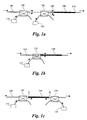
- FIG. 1a the principle setup of a dual pumping optical amplifier is schematically illustrated.
- the signal in the S-band typically of wavelength 1470 nm is carried in the signal medium 100, for example an optical fiber.
- a first pumping device 110 with a first pumping wavelength ⁇ p1 , is optically coupled to the signal medium 100, for example through a first WDM fiber coupler unit 120.
- a second pumping wavelength, ⁇ p2 is produced by a second pumping device 130, which is optically coupled to the signal medium 100, for example through a second WDM fiber coupler unit 140.
- the stimulated emission of photons, i.e. the amplification takes place in the amplifier fiber 150 of thulium doped material.
- the amplifier fiber has an input 160 for receiving the input signal and the co-propagating photons from the pumping devices, and an output 170 for the amplified optical signal.
- the solid arrows indicate the direction of the signal and the dashed arrows the direction of the pumping light.
- an amplifying assembly may be realized in a large variety of ways.
- FIG 1b schematically illustrates one common alternative way of coupling the signal and the pump light to the amplifying fiber.
- a WDM fiber coupler unit 125 is used to couple the pumping light produced by a pumping device 115 and the signal carried in the signal medium 100 directly to the amplifier fiber 150. Hence, the WDM fiber coupler unit is itself the place were the signal and the pumping light are coupled to the amplifying fiber.
- the pumping light may be coupled counterpropagating with the signal to be amplified, or split so that one pump wavelength co-propagates and the other pump wavelength counter-propagates with the signal.
- a amplifying setup is schematically illustrated in FIG 1c.
- the signal in the S-band typically of wavelength 1470 nm is carried in the signal medium 100.
- the first pumping wavelength ⁇ p1 is produced by the first pumping device 110.
- the first WDM fiber coupler unit 120 couples the first pumping wavelength and the signal to one end of the amplifying fiber 150.
- the second WDM fiber coupler unit 140 couples the second pumping wavelength, ⁇ p2 , produced by a second pumping device 130, to the other end of the amplifying fiber 150.
- the second WDM fiber coupler unit 140 also provides an output 175 for the amplified signal. This setup may be advantageous to separate the remaining pump light from the amplified signal.
- the WDM fiber coupler unit associated with one wavelength also helps removing light of the other wavelength which was not absorbed by the amplifying fiber.
- the light of different wavelength produced in the pumping devices 110, 130 may originate from various commercially available light sources including, fiber lasers, tunable lasers and laser diodes. For commercial applications, then the price and reliability is of high importance, the laser diodes are particularly interesting. Laser diodes producing light of suitable wavelength are commercially available.
- the method according to the invention the dual wavelength pumping scheme will be described with references to FIG. 2, which illustrates the energy levels of thulium doped fiber amplifier.
- the first pumping wavelength, ⁇ p1 according to the invention should preferably be around 800nm followed by the second pumping wavelength, ⁇ p2 , preferably of around 1050nm or 980nm.
- the choice of wavelengths has been shown to, compared to prior art pumping schemes, give a surprisingly good result as regards to gain, frequency dependence and amplification.
- the main advantage of the scheme according to the invention relies on the fact that the ⁇ p1 ⁇ 800nm pump wavelength populates the upper amplifying level 3 H 4 by single photon absorption, as indicated in FIG. 2.
- the absorption cross section is high (see table I below), ensuring an effective utilization of the pumping power.
- the second wavelength, ⁇ p2 helps primarily to depopulate the lower level 3 F 4 , by excited absorption of a single photon.
- the transition given by ⁇ p2 ⁇ 1050nm, by strong excited state absorption (ESA) to level 3F2 occurs with a high probability (see cross section in table I). It also simultaneously populates the level 3 H 4 (through 3F2), both effects beneficial to creating the population inversion.
- FIG. 3 The advantages of the inventive pumping scheme is illustrated in FIG. 3 in which the ⁇ 1470nm amplified spontaneous emission (ASE) band when pumped by each individual wavelength, ⁇ p1 and ⁇ p2 respectively, and both wavelengths together. From FIG. 3 the dramatic increase in ASE power when the two wavelengths are used together, compared to when each one pumps the TDFA individually, should be evident.
- FIG. 4 The advantages of the present invention is further illustrated in FIG. 4, which in a graph illustrates the gain and noise figure for the inventive dual pumping scheme. The enhancement in the small signal gain when the ⁇ 800nm wavelength is added to the 1050nm pump (filled squares in the figure) is striking.
- a noise figure (filled triangles) of less than 5dB was measured for the dual pumping, which is close to the expected limit of 3dB for TDFA's.
- the gain may be further optimized by adjusting the pumping power of the two wavelengths. For example, a gain of 27dB was obtained for a total pump power of 180mW (100mW of 1050nm and 80mW of 794nm). Optimization of the TDFA in terms of gain and gain flatness can be obtained by adjusting the Thulium ion concentration, the doped fiber length, and the exact wavelength and power of the two pumps.
- the wavelengths are typically and preferably within ⁇ p1 ⁇ 800nm ⁇ 10nm and ⁇ p2 ⁇ 1055nm ⁇ 10nm, respectively or alternatively ⁇ p1 ⁇ 800nm ⁇ 10nm and ⁇ p2 ⁇ 980nm ⁇ 10nm, respectively.
- the pumping method according to the invention may be summarized in the following main steps:
- a diode-pumped Yb-fiber laser operating at 1050nm can be used for ⁇ p2 .
- a Ti-sapphire tunable cw laser can be used for the other pump source at ⁇ p1 ⁇ 800mn.
- a cw semiconductor diode laser represents a lower cost alternative.
- a single channel test signal may be provided by a cw tunable laser diode source, but WDM operation is also feasible.
- Thulium doped fibers are commercially available, for example from Le Verre Fluoré.
- Typical characteristics for a so called ZBLAN (ZrF 4 -BaF 2 -LaF 3 -AlF 3 -NaF) fiber suitable for the inventive method is presented in table II.
- Fibre #1 (from Le Verre Fluoré) Fiber Type Single mode Fiber composition ZrF 4 -BaF 2 -LaF 3 -AlF 3 -NaF Fiber identification 011010/28671 Pigtail fibre* Standard Silica Fibre Dopant Tm 3+ Doping Concentration 2000ppm molar NA 0.24 Cutoff wavelength 880nm Core diameter 2.8 ⁇ m Clad diameter 125 ⁇ m Fiber length 15m
- the above described ZBLAN fiber should be considered as a non limiting example. Many of the material parameters may be varied and the material could still serve as the gain material in an optical amplifier. Some of the parameters may even be varied to optimize the performance of the amplifying assembly, for example the Tm doping concentration.
- the Tm doping concentration is typically 2000 ppm, but other concentrations display promising results, particularly higher concentrations. Even Tm doping concentrations around 5000 ppm could be advantageous to use in combination with the pumping scheme according to the invention.
- optical fibers are based on silica glass, which is stable even at high temperatures and can be spliced with available machines with very low loss.
- silica fibers are not compatible with Tm-amplifiers in the S-band because of phonon scattering. Therefore, fibers based on fluoride materials such as ZBLAN are used.
- fluoride materials such as ZBLAN are used.
- Other types of fiber materials are constantly developed, tested and used, for example the, Telluride fibers. Developments in the area will most probably lead to the use of silica or silica-compatible fibers in the near future.
- the pumping scheme according to the present invention could advantageously be used with all these types of fibers, including the silica based ones.
- the pumping scheme according to the invention is not limited to the above described amplifying assembly. On the contrary, a large variety of assemblies may advantageously use the aforementioned pumping scheme. It may, e.g. also be used inside an optical cavity, so that a laser is embodied.
- the active ions can be incorporated in an optical fiber, as will be further described below. They can also be incorporated in a crystal, such as those used in the so-called microchip lasers.
- the pumping scheme described above is equally useful to provide optical excitation to the Tm laser. The large bandwidth intrinsic to the ion results in a potentially widely tunable laser.
- the Tm doped material can be used for the purpose of lasing in the 1.4-1.52 ⁇ m wavelength region.
- the doped material is a single mode optical fiber with Tm ions in the core 500 and neodymium (Nd) ions in an inner cladding 510, surrounded by an outer cladding 520.
- Nd neodymium
- the Nd ions contained in the inner cladding of the fiber absorb some of the photons at 800 nm and emit radiation in the 1050 nm region, which is in turn absorbed in the single core by the Tm ions.
- the inner cladding configuration has the advantage of helping making most use of the poorly collimated radiation from a semiconductor diode laser at 800 nm, since the effective area of the inner cladding is much greater than of the single mode core of the fiber.
- One way of depositing the energy to the rare earth doped material according to the invention is to utilize in radiation from the semiconductor lasers for pumping a fiber laser and also the Tm-doped fiber.
- This embodiment is schematically illustrated in FIG. 6, in which a fiber laser is provided with an optical cavity 600 where the Nd-doped fiber providing optical gain is placed between two fiber Bragg gratings M1 and M2, respectively.
- a semiconductor laser 605 provide the 800nm which drives the fiber laser.
- the optical cavity is coupled to the Tm-doped fiber amplifier 150.
- the gratings may be made on the same piece of Nd-doped fiber, or on pieces of fiber that are subsequently spliced to the Nd-doped fiber.
- the wavelengths reflected by the Bragg gratings are close to 1050-1060 nm, so that the fiber laser reaches threshold.
- the reflectivity of the mirror M1 can be preferentially close to 100% at the lasing wavelength (1.06 ⁇ m) and close to 0% at the pumping wavelength (800 nm).
- the reflectivity of grating M2 should be less than 100% at the lasing wavelength and close to 0% at the pumping wavelength. In this way, the radiation reaching the Tm-doped fiber in the fiber amplifier 150 is the sum of the fiber-laser light and the fraction of the 800 nm pump light that has not been absorbed by the Nd-doped fiber.
- the fiber laser is realized by a ring configuration of Nd-doped fiber 700 driven by a semiconductor diode laser providing 800 nm radiation.
- a small part (around 10%) of the radiation generated at 1050 nm in the ring laser would be circulated to keep the laser above threshold, while most of the radiation available at 1050 nm would be used for pumping the Tm-fiber.
- the numbers given should be regarded as a non limiting example to explain the principle of operation.
- the mirrors to be used can be preferentially fiber Bragg gratings, that can conveniently be highly reflective at the pump wavelengths (800 nm and 1050 nm), and highly transmitting at the signal wavelengths to be amplified.
- the gratings could be incorporated in a piece of silica based fiber that is connected to the Tm-doped fluor-based fiber and constitutes the output fiber of the amplifier.
- the Bragg gratings may be provided at or close to the endpoints of the amplifying fiber, denoted with A and B, respectively.
- the Bragg gratings are arranged to reflect back the wavelengths 1050 nm and 800nm, respectively.
- the idea here disclosed is not exclusive of other techniques known in the prior art to improve the performance of rare-earth doped amplifiers.
- the use of gain equalizing filters such as fiber Bragg gratings is clearly a possibility in conjunction with the pumping scheme disclosed in the present invention.
- the filters could be conveniently placed at the output of the amplifier.
- the Bragg grating can be fabricated in the output fiber, for example a silica-based fiber.
Abstract
Description
- The present invention relates generally to the field of optical communication and particularly to an optical thulium doped fiber amplifier utilizing a dual wavelength pumping scheme for amplifying an optical signal.
- The widespread and increasing use of fiber optics for communication purposes has brought considerable attention to means for increasing the communication capacity of the fibers. The use of Wavelength Division Multiplexing (WDM) signals is an effective way of increasing transmission capacity, since a plurality of separated wavelength bands, each band capable of transmitting signals, is simultaneously used in a fiber.
- Optical amplifiers are used to compensate for the fiber link and splitting losses within optical communication systems. The WDM technique requires amplification in a broad wavelength spectrum, which is typically realized by letting a plurality of optical amplifiers, each operational in a part of the wavelength spectrum, operate in parallel. Various rare-earth doped optical amplifiers, in the form of amplification fibers, suitable for WDM are known in the art. The optical fiber amplifier typically consists of an optical material such as glass, combined with a rare earth dopant and configured as an optical waveguide. Rare-earth-doped silica fibers are popular today, in part because they offer the advantages of single-mode guided wave optics. Optical fiber amplifiers can be made to operate over a broad range of wavelengths, dictated by the atomic properties of the host and rare earth dopant. In their basic operation pump light from a pump source is used to excite the dopant atoms in the amplification fiber from a ground state to a metastable state. The excited atoms are, by an incident signal of a characteristic wavelength, stimulated to emit energy in form of a light of the same wavelength, the emission resulting in an amplification of the signal. The process is known as stimulated emission. After the stimulated emission the atom is in a termination state. The gain should be high, the efficiency too. The gain of the amplifier, defined as the power of the signal out divided by the power of the signal in, should be as high as possible. Also, the efficiency of the amplifier, measured as the gain achieved for a particular pump power, should be as high as possible. In addition the gain should preferably be essentially flat, i.e. not depending on the frequency of the incident light, over the frequency range in which the amplifier is intended to be used.
- For amplification in the so called S-band (1450-1520 nm) much interest has been given to thulium doped fiber amplifiers (TDFA). The useful transition for the stimulated emission is between the metastable 3H4 level to the lower 3F4 termination level, giving an output signal of wavelength around 1470 nm. A well recognized problem with using TDFA as an optical amplifier is that the 3H4 level has a short lifetime compared to the 3F4 level. In practice this results in that, even if the pumping excitation to the 3H4 level is successfully achieved, the stimulated emission will be impaired due to the accumulation of population at the 3F4 level. This results in a poor gain.
- Several attempts for increasing the gain of the TDFA have been reported, including up-conversion pumping with repeated pumping with the same wavelength and various dual wavelength pumping schemes as for example presented in the following: F. Roy, D. Bayart, A. Le Sauze and P. Baniel, "Noise and gain band management of thulium-doped fiber amplifier with dual-wavelength pumping schemes," IEEE Photon. Technol. Lett., 13, 788-790, (2001); T. Kasamatsu, Y. Yano and H. Sekita, "1.50-µm-band gain-shifted thulium-doped fiber amplifier with 1.05- and 1.56-µm dual-wavelength pumping," Opt. Lett., 24, 1684-1686, (1999); T. Kasamatsu, Y. Yano and T. Ono, "Laser-diode pumping (1.4 and 1.56µm) of gain-shifted thulium-doped fiber amplifier," Electron. Lett., 36, 1607-1609, (2000); T. Kasamatsu, Y. Yano, and T. Ono, "Gain-shifted dual-wavelength-pumped thulium-doped fiber amplifier for WDM signals in the 1.48-1.51-µm wavelength region," IEEE Photon. Technol. Lett., 13, 31-33, 2001; F Roy, F. Leplingard, L. Lorcy, A. Le Sauze, P Baniel,. D. Bayart, "48% power conversion efficiency in single pump gain-shifted thulium-doped fibre amplifier". Electronics Letters, 37:15, 943 - 945, 2001; T. Kasamatsu, Y. Yano, T. Ono, "Laser-diode-pumped highly efficient gain-shifted thulium-doped fiber amplifier operating in the 1480-1510-nm band", IEEE Photonics Technology Letters, 13:5, 433-435, 2001; Tadashi Sakamoto, "S-band fiber optic amplifiers", Optical Fiber Communication Conference and Exhibit, 2 TuQ1-1 - TuQ1-4, 2001; B.Cole, M.L. Dennis, "S-band amplification in a thulium doped silicate fiber" Optical Fiber Communication Conference and Exhibit, 2, TuQ3-1 -TuQ3-3, 2001;. T. Kasamatsu, Y. Yano, T. Ono, "Laser-diode-pumped highly-efficient gain-shifted thulium doped fiber amplifier operating in the 1480-1510-nm band" Optical Fiber Communication Conference and Exhibit, 2, TuQ4-1 -TuQ4-3, 2001; F. Roy, P. Baniel, C. Fages, J.J. Girard, A. Le Sauze, D. Bayart, "Optimal pumping schemes for gain-band management of thulium-doped fiber amplifiers", Optical Fiber Communication Conference and Exhibit, 2, TuQ7-1 - TuQ7-4, 2001; F. Roy, F. Leplingard, L. Lorcy, A. Le Sauze, P. Baniel, D. Bayart, "48% power conversion efficiency in a single-pump gain-shifted thulium-doped fiber amplifier", Optical Fiber Communication Conference and Exhibit, PD2_1 - PD2_3, 2001; F. Roy, D. Bayart, P. Baniel, and "Nove1 pumping schemes for thulium doped fiber amplifier" Optical Fiber Communication Conference, 2, 14 -16, 2000.
- In the dual wavelength pumping process, the first photon populates the lower 3F4 level whereas the second photon is responsible for populating the higher 3H4 level and at the same time depopulating the 3F4 (lower) level to allow for population inversion. The reported wavelengths have been 1050-1550 nm for the first pumping and around 1400 for the second pumping and typically a total pump power of 200-500mW are needed to reach a 27 dB gain.
- Disclosed in US patent 6,407,853 is a dual pumping scheme suitable for TDFA. A first pumping wavelength of preferably 800 nm excite the dopant from the ground level (3H6) directly to the 3H4 level. A second pumping wavelength of 1440 nm is used to depopulate the 3F4 level and hence facilitating the stimulated emission.
- Document XP 951877 (Optics Letters, vol. 25, no. 11, 2000-06-20, p 817-819, Tanabe et al., "Improved emission of Tm3+ doped glass for a 1,4 µm amplifier by radiative energy transfer between Tm3+ and Nd3+") discloses a similar method and device.
- The prior art represent significant improvements in the use of thulium doped fiber amplifiers. However, for widespread use in communication systems it is necessary to further increase the efficiency of the amplifiers as well as to use pump wavelengths which are achievable with low cost semiconductor lasers.
- The objective problem is to provide a method and an apparatus for amplifying an optical signal with a high gain and with high power efficiency as to facilitate production of effective optical amplifiers at reasonable costs.
- The problem is solved by the assembly as defined in
claim 10, and the method as defined in claim 1. - The method of amplifying an optical signal in a thulium doped fiber amplifier according to the invention comprising the steps of: a first deposition of energy into the fiber amplifier by pumping with radiation of a first wavelength; and a second deposition of energy into the fiber amplifier by pumping with radiation of a second wavelength. The radiation of the first wavelength is arranged to induce, by single photon absorption, a population to the 3H4 level of the thulium dopant, and the radiation of the second wavelength primarily depopulates the 3F4 level, by excited absorption of a single photon, preferably by strong excited state absorption to the 3F2 level. These steps achieve a population inversion between the 3H4 and the 3F4 levels and facilitate a power efficient high gain amplification.
- The amplifying assembly for amplifying an optical signal in a thulium doped fiber amplifier according to the invention comprises: a first energy depositing means for depositing energy into the fiber amplifier by pumping with radiation of a first wavelength, and a second energy depositing means for depositing energy into the fiber amplifier by pumping with radiation of a second wavelength. The radiation of the first wavelength is arranged to induce, by single photon absorption, a population to the 3H4 level of the thulium dopant, and the radiation of the second wavelength primarily depopulates the 3F4 level, by excited absorption of a single photon, preferably by strong excited state absorption to the 3F2 level, whereby achieving a population inversion between the 3H4 and the 3F4 levels.
- One advantage afforded by the arrangement and method according to the invention is that a high amplification gain is achieved using relatively low power.
- Another advantage afforded by the invention is that low cost laser diodes may be used.
- A main advantage by the arrangement and method according to the invention is that low cost, yet effective, and hence commercially attractive, optical amplifiers may be produced.
- The features and advantages of the present invention outlined above are described more fully below in the detailed description in conjunction with the drawings where like reference numerals refer to like elements throughout, in which:
- Fig. 1a-c are schematic drawings of a dual wavelength pumping assemblies according to the invention;
- Fig. 2 is a schematic illustration of relevant energy levels and transitions in a Tm dopant atom;
- Fig. 3 is a graph showing the amplified spontaneous emission of thulium using the method of the invention;
- Fig. 4 is a graph showing the gain using the method of the invention;
- Fig. 5 is a schematic drawing of an embodiment of the invention;
- Fig. 6 is a schematic drawing of an embodiment of the invention; and
- Fig.7 is a schematic drawing of an embodiment of the invention.
- Embodiments of the invention will now be described with reference to the figures.
- In FIG. 1a the principle setup of a dual pumping optical amplifier is schematically illustrated. The signal in the S-band, typically of
wavelength 1470 nm is carried in thesignal medium 100, for example an optical fiber. Afirst pumping device 110, with a first pumping wavelength λp1, is optically coupled to thesignal medium 100, for example through a first WDMfiber coupler unit 120. A second pumping wavelength, λp2, is produced by asecond pumping device 130, which is optically coupled to thesignal medium 100, for example through a second WDMfiber coupler unit 140. The stimulated emission of photons, i.e. the amplification takes place in theamplifier fiber 150 of thulium doped material. The amplifier fiber has aninput 160 for receiving the input signal and the co-propagating photons from the pumping devices, and anoutput 170 for the amplified optical signal. In FIG 1 a-c the solid arrows indicate the direction of the signal and the dashed arrows the direction of the pumping light. As realized by the skilled in the art an amplifying assembly may be realized in a large variety of ways. - FIG 1b schematically illustrates one common alternative way of coupling the signal and the pump light to the amplifying fiber. A WDM
fiber coupler unit 125 is used to couple the pumping light produced by apumping device 115 and the signal carried in thesignal medium 100 directly to theamplifier fiber 150. Hence, the WDM fiber coupler unit is itself the place were the signal and the pumping light are coupled to the amplifying fiber. - Alternatively, the pumping light may be coupled counterpropagating with the signal to be amplified, or split so that one pump wavelength co-propagates and the other pump wavelength counter-propagates with the signal. Such a amplifying setup is schematically illustrated in FIG 1c. The signal in the S-band, typically of
wavelength 1470 nm is carried in thesignal medium 100. The first pumping wavelength λp1, is produced by thefirst pumping device 110. The first WDMfiber coupler unit 120 couples the first pumping wavelength and the signal to one end of the amplifyingfiber 150. The second WDMfiber coupler unit 140 couples the second pumping wavelength, λp2, produced by asecond pumping device 130, to the other end of the amplifyingfiber 150. The second WDMfiber coupler unit 140 also provides an output 175 for the amplified signal. This setup may be advantageous to separate the remaining pump light from the amplified signal. The WDM fiber coupler unit associated with one wavelength also helps removing light of the other wavelength which was not absorbed by the amplifying fiber. - The light of different wavelength produced in the
pumping devices - Embodiments of amplifying assemblies carrying out the method of the invention will be given below.
- The method according to the invention, the dual wavelength pumping scheme will be described with references to FIG. 2, which illustrates the energy levels of thulium doped fiber amplifier. The first pumping wavelength, λp1, according to the invention should preferably be around 800nm followed by the second pumping wavelength, λp2, preferably of around 1050nm or 980nm. The choice of wavelengths has been shown to, compared to prior art pumping schemes, give a surprisingly good result as regards to gain, frequency dependence and amplification.
- The main advantage of the scheme according to the invention relies on the fact that the λp1~800nm pump wavelength populates the upper amplifying level 3H4 by single photon absorption, as indicated in FIG. 2. The absorption cross section is high (see table I below), ensuring an effective utilization of the pumping power. The second wavelength, λp2, helps primarily to depopulate the lower level 3F4, by excited absorption of a single photon. The transition given by λp2~1050nm, by strong excited state absorption (ESA) to level 3F2, occurs with a high probability (see cross section in table I). It also simultaneously populates the level 3H4 (through 3F2), both effects beneficial to creating the population inversion. As is well known, 1050nm pumping alone is useful to provide amplification but at the expense of high power due to the very low ground state absorption (GSA) to level 3F4 through 3H5, whose cross section should not differ much from the 1064nm cross section shown in table I. The use of λp2~980nm, which represent an alternative embodiment of the invention, results in a population inversion, but is slightly less effective. However, to use λp2~980nm might be commercially attractive as powerful and cheap laser diodes giving 980nm are available.
Table I - Cross Section for several transitions in Thulium doped ZBLAN fibres Transition and wavelength Cross section (σ)-pm2 Description Ref. 3H6 → 3H4 at 790nm 0.33 ± 0.01 Absorption (GSA) [2] 3H6 → 3H5 at 1064nm 0.0011 Absorption (GSA) - estimated [1], [3] 3F4 → 3F2 at 1055nm (peak) 1.2 Absorption (ESA) - estimated [1], [3] 3P4 → 3F2 at 1064nm 0.82 Absorption (ESA) - estimated [1], [3] 3H4 → 3F4 at 1469nm 0.67 Stimulated-emission [1] - The advantages of the inventive pumping scheme is illustrated in FIG. 3 in which the ~1470nm amplified spontaneous emission (ASE) band when pumped by each individual wavelength, λp1 and λp2 respectively, and both wavelengths together. From FIG. 3 the dramatic increase in ASE power when the two wavelengths are used together, compared to when each one pumps the TDFA individually, should be evident. The advantages of the present invention is further illustrated in FIG. 4, which in a graph illustrates the gain and noise figure for the inventive dual pumping scheme. The enhancement in the small signal gain when the ~800nm wavelength is added to the 1050nm pump (filled squares in the figure) is striking. It is worth noting that the ~800nm pump alone does not suffice to create a population inversion, whereas the 1050nm pump alone does. However, for the pump power at 1050nm employed, a very small gain (all gains described here are internal, i.e., fiber gain) approximately 7-8dB is obtained (unfilled squares). Previous measurements on this fiber have shown that gains of over 20dB can be obtained with pumping at 1050nm alone, but for very high powers (over 300 mW). In our dual wavelength pumped TDFA, for a total of 153mW pump power, a gain of more than 20dB over a bandwidth of approximately 40nm was obtained. A noise figure (filled triangles) of less than 5dB was measured for the dual pumping, which is close to the expected limit of 3dB for TDFA's. The gain may be further optimized by adjusting the pumping power of the two wavelengths. For example, a gain of 27dB was obtained for a total pump power of 180mW (100mW of 1050nm and 80mW of 794nm). Optimization of the TDFA in terms of gain and gain flatness can be obtained by adjusting the Thulium ion concentration, the doped fiber length, and the exact wavelength and power of the two pumps. The wavelengths are typically and preferably within λp1~800nm±10nm and λp2~1055nm±10nm, respectively or alternatively λp1~800nm±10nm and λp2~980nm±10nm, respectively.
- The pumping method according to the invention may be summarized in the following main steps:
- (a) a first deposition of energy into the fiber amplifier by pumping with radiation of a first wavelength which, by single photon absorption, induces a population to the 3H4 level of the thulium dopant. The first wavelength is preferably 800nm±10nm.
- (b) a second deposition of energy into the fiber amplifier by pumping with radiation of a second wavelength which depopulates the 3F4 level, by excited absorption of a single photon, preferably by strong excited state absorption to the 3F2 level. In addition the radiation of the second wavelength simultaneously populates the 3H4 level through the 3F2 level. The second wavelength is preferably 1055nm±10nm or alternatively 980nm±10nm.
- The two main steps achieving a population inversion between the 3H4 and the 3F4 levels, and hence a significant increase in gain and amplification.
- As an example of implementation, and the setup utilized for the above presented results, a diode-pumped Yb-fiber laser operating at 1050nm can be used for λp2. For the other pump source at λp1 ~800mn, a Ti-sapphire tunable cw laser can be used. A cw semiconductor diode laser represents a lower cost alternative. A single channel test signal may be provided by a cw tunable laser diode source, but WDM operation is also feasible. Thulium doped fibers are commercially available, for example from Le Verre Fluoré. Typical characteristics for a so called ZBLAN (ZrF4-BaF2-LaF3-AlF3-NaF) fiber suitable for the inventive method is presented in table II.
Table II - Characteristics of a Thulium doped ZBLAN fiber. Fibre #1 (from Le Verre Fluoré) Fiber Type Single mode Fiber composition ZrF4-BaF2-LaF3-AlF3-NaF Fiber identification 011010/28671 Pigtail fibre* Standard Silica Fibre Dopant Tm3+ Doping Concentration 2000ppm molar NA 0.24 Cutoff wavelength 880nm Core diameter 2.8µm Clad diameter 125µm Fiber length 15m - The above described ZBLAN fiber should be considered as a non limiting example. Many of the material parameters may be varied and the material could still serve as the gain material in an optical amplifier. Some of the parameters may even be varied to optimize the performance of the amplifying assembly, for example the Tm doping concentration. The Tm doping concentration is typically 2000 ppm, but other concentrations display promising results, particularly higher concentrations. Even Tm doping concentrations around 5000 ppm could be advantageous to use in combination with the pumping scheme according to the invention.
- Many commercially used optical fibers are based on silica glass, which is stable even at high temperatures and can be spliced with available machines with very low loss. At present, silica fibers are not compatible with Tm-amplifiers in the S-band because of phonon scattering. Therefore, fibers based on fluoride materials such as ZBLAN are used. Other types of fiber materials are constantly developed, tested and used, for example the, Telluride fibers. Developments in the area will most probably lead to the use of silica or silica-compatible fibers in the near future. As appreciated by the skilled in the art the pumping scheme according to the present invention could advantageously be used with all these types of fibers, including the silica based ones.
- The pumping scheme according to the invention is not limited to the above described amplifying assembly. On the contrary, a large variety of assemblies may advantageously use the aforementioned pumping scheme. It may, e.g. also be used inside an optical cavity, so that a laser is embodied. The active ions can be incorporated in an optical fiber, as will be further described below. They can also be incorporated in a crystal, such as those used in the so-called microchip lasers. The pumping scheme described above is equally useful to provide optical excitation to the Tm laser. The large bandwidth intrinsic to the ion results in a potentially widely tunable laser. The Tm doped material can be used for the purpose of lasing in the 1.4-1.52 µm wavelength region.
- One embodiment of the invention will be described with references to FIG. 5 in which the doped material is a single mode optical fiber with Tm ions in the
core 500 and neodymium (Nd) ions in aninner cladding 510, surrounded by anouter cladding 520. In this embodiment, only a 800 nm light source is required for external pumping, for example asemiconductor diode laser 530. The Nd ions contained in the inner cladding of the fiber absorb some of the photons at 800 nm and emit radiation in the 1050 nm region, which is in turn absorbed in the single core by the Tm ions. The inner cladding configuration has the advantage of helping making most use of the poorly collimated radiation from a semiconductor diode laser at 800 nm, since the effective area of the inner cladding is much greater than of the single mode core of the fiber. - One way of depositing the energy to the rare earth doped material according to the invention is to utilize in radiation from the semiconductor lasers for pumping a fiber laser and also the Tm-doped fiber. This embodiment is schematically illustrated in FIG. 6, in which a fiber laser is provided with an
optical cavity 600 where the Nd-doped fiber providing optical gain is placed between two fiber Bragg gratings M1 and M2, respectively. Asemiconductor laser 605 provide the 800nm which drives the fiber laser. The optical cavity is coupled to the Tm-dopedfiber amplifier 150. The gratings may be made on the same piece of Nd-doped fiber, or on pieces of fiber that are subsequently spliced to the Nd-doped fiber. The wavelengths reflected by the Bragg gratings are close to 1050-1060 nm, so that the fiber laser reaches threshold. The reflectivity of the mirror M1 can be preferentially close to 100% at the lasing wavelength (1.06 µm) and close to 0% at the pumping wavelength (800 nm). The reflectivity of grating M2 should be less than 100% at the lasing wavelength and close to 0% at the pumping wavelength. In this way, the radiation reaching the Tm-doped fiber in thefiber amplifier 150 is the sum of the fiber-laser light and the fraction of the 800 nm pump light that has not been absorbed by the Nd-doped fiber. - In an alternative embodiment, schematically depicted in FIG. 7, the fiber laser is realized by a ring configuration of Nd-doped
fiber 700 driven by a semiconductor diode laser providing 800 nm radiation. A small part (around 10%) of the radiation generated at 1050 nm in the ring laser would be circulated to keep the laser above threshold, while most of the radiation available at 1050 nm would be used for pumping the Tm-fiber. The numbers given should be regarded as a non limiting example to explain the principle of operation. - In order to reduce the length of Tm-doped fiber required for maximum gain, it is possible to propagate the pump light along the Tm-doped fiber, and then to reflect the remaining part of the pump light that was not absorbed. The mirrors to be used can be preferentially fiber Bragg gratings, that can conveniently be highly reflective at the pump wavelengths (800 nm and 1050 nm), and highly transmitting at the signal wavelengths to be amplified. The gratings could be incorporated in a piece of silica based fiber that is connected to the Tm-doped fluor-based fiber and constitutes the output fiber of the amplifier. Referring to the schematically illustrated setup of FIG 1c the Bragg gratings may be provided at or close to the endpoints of the amplifying fiber, denoted with A and B, respectively. The Bragg gratings are arranged to reflect back the
wavelengths 1050 nm and 800nm, respectively. - It should be understood that the idea here disclosed is not exclusive of other techniques known in the prior art to improve the performance of rare-earth doped amplifiers. For example, the use of gain equalizing filters such as fiber Bragg gratings is clearly a possibility in conjunction with the pumping scheme disclosed in the present invention. Here, the filters could be conveniently placed at the output of the amplifier. In this way, the Bragg grating can be fabricated in the output fiber, for example a silica-based fiber.
- While the invention has been described in connection with what is presently considered to be the most practical and preferred embodiments, it is to be understood that the invention is not to be limited to the disclosed embodiments, but on the contrary, is intended to cover various modifications and equivalent arrangements included within the scope of the appended claims.
Claims (23)
- A method of amplifying an optical signal in a thulium doped fiber amplifier comprising the steps of:- a first deposition (a) of energy into the fiber amplifier by pumping with radiation of a first wavelength; and- a second deposition (b) of energy into the fiber amplifier by pumping with radiation of a second wavelength;the radiation of the first wavelength by single photon absorption populates the 3H4 level of the thulium dopant, and the radiation of the second wavelength depopulates the 3F4 level by strong excited state absorption of a single photon to the 3F2 level and simultaneously populates the 3H4 level through the 3F2 level, whereby achieving a population inversion between the 3H4 and the 3F4 levels.
characterized in that the radiation of the first wavelength (λ1) has a wavelength of around 800 nm. - The optical amplifying method according to claim 2, wherein the radiation of the first wavelength (λ1) has a wavelength of 800 ±10nm.
- The optical amplifying method according to claim 1, wherein the radiation of the second wavelength (λ2) has a wavelength of around 1050 nm.
- The optical amplifying method according to claim 4, wherein the radiation of the second wavelength (λ2) has a wavelength of around 1050 ±10nm.
- The optical amplifying method according to claim 1, wherein the radiation of the second wavelength has a wavelength of around 980 nm.
- The optical amplifying method according to claim 6, wherein the radiation of the second wavelength has a wavelength of around 980 ±10nm.
- The optical amplifying method according to claim 1, further comprising the step of reflecting at least one of the radiations of the first and second wavelengths by a at least one Bragg grating, whereby facilitating a reduction of length of the thulium doped fiber amplifier without essentially affecting the amplification gain.
- The optical amplifying method according to claim 1, wherein the radiation of the first or second wavelength is generated from the radiation of the second or first wavelength, respectively.
- The optical amplifying method according to claim 9, wherein the radiation of the first or second wavelength is generated in an optically amplifying material incorporated in an amplifying assembly, the generation of radiation of the first or second wavelength thus induced by the radiation of the second or first wavelength, respectively.
- An amplifying assembly for amplifying an optical signal in a thulium doped fiber amplifier comprising:a first energy depositing means (120) for depositing energy into the fiber amplifier by pumping with radiation of a first wavelength; anda second energy depositing means (140) for depositing energy into the fiber amplifier by pumping with radiation of a second wavelength;the radiation of the first wavelength by single photon absorption populates the 3H4 level of the thulium dopant, and the radiation of the second wavelength primarily depopulates the 3F4 level by strong excited state absorption of a single photon to the 3F2 level and simultaneously populates the 3H4 level through the 3F2 level, whereby achieving a population inversion between the 3H4 and the 3F4 levels,
characterized in that the radiation of the first wavelength has a wavelength of around 800 nm. - The amplifying assembly according to claim 12, wherein the radiation of the first wavelength has a wavelength of 800 ±10nm.
- The amplifying assembly according to claim 11, wherein the radiation of the second wavelength has a wavelength of around 1050 nm.
- The amplifying assembly according to claim 14, wherein the radiation of the second Wavelength has a wavelength of around 1050 ±10nm.
- The amplifying assembly according to claim 11, wherein the radiation of the second wavelength has a wavelength of around 980 nm.
- The amplifying assembly according to claim 14, wherein the radiation of the second wavelength has a wavelength of around 980 ±10nm.
- The amplifying assembly according to claim 11, wherein the radiation of the first and/or second wavelength is produced by laser diodes.
- The amplifying assembly according to claim 11, wherein the radiation of the first or second wavelength is generated from the radiation of the second or first wavelength, respectively.
- The amplifying assembly according to claim 19, further comprising means for generating radiation incorporated in the amplifying assembly, wherein the radiation of the first or second wavelength is generated by the means for generating radiation using the radiation of the second or first wavelength, respectively.
- The amplifying assembly according to claim 20, wherein the means for generating radiation is provided as a core of thulium doped fiber (500) surrounded by a cladding comprising neodymium (Nd) ions (510) and adopted to absorb some of the radiation at the first wavelength and emit radiation at the second wavelength.
- The amplifying assembly according to claim 20, wherein the means for generating radiation is a fiber laser driven by the radiation of the first wavelength.
- The amplifying assembly according to claim 22, wherein the fiber laser is a ring configuration of neodymium (Nd)-doped fiber driven by a semiconductor diode laser providing radiation of the first wavelength.
- The amplifying assembly according to claim 22, wherein the fiber laser comprises an optical cavity (600) in which a neodymium (Nd)-doped fiber is placed between two fiber Bragg gratings.
- The amplifying assembly according to any of claims 11 to 15, further comprising at least one Bragg grating adapted for reflecting at least one of the radiation of the first and second wavelengths by, whereby facilitating a reduction of length of the thulium doped fiber amplifier without essentially affecting the amplification gain.
Applications Claiming Priority (5)
| Application Number | Priority Date | Filing Date | Title |
|---|---|---|---|
| US36343802P | 2002-03-11 | 2002-03-11 | |
| US363438P | 2002-03-11 | ||
| US36513302P | 2002-03-14 | 2002-03-14 | |
| US365133P | 2002-03-14 | ||
| PCT/BR2003/000033 WO2003077384A1 (en) | 2002-03-11 | 2003-03-11 | Methods and arrangements in a pumped fiber amplifier |
Publications (2)
| Publication Number | Publication Date |
|---|---|
| EP1483811A1 EP1483811A1 (en) | 2004-12-08 |
| EP1483811B1 true EP1483811B1 (en) | 2006-12-27 |
Family
ID=27807993
Family Applications (1)
| Application Number | Title | Priority Date | Filing Date |
|---|---|---|---|
| EP03707939A Expired - Lifetime EP1483811B1 (en) | 2002-03-11 | 2003-03-11 | Methods and arrangements in a pumped fiber amplifier |
Country Status (11)
| Country | Link |
|---|---|
| US (1) | US7113328B2 (en) |
| EP (1) | EP1483811B1 (en) |
| JP (1) | JP2005520327A (en) |
| CN (1) | CN1653657A (en) |
| AT (1) | ATE349789T1 (en) |
| AU (1) | AU2003212127A1 (en) |
| BR (1) | BR0308356A (en) |
| CA (1) | CA2478360A1 (en) |
| DE (1) | DE60310689T2 (en) |
| HK (1) | HK1071966A1 (en) |
| WO (1) | WO2003077384A1 (en) |
Families Citing this family (15)
| Publication number | Priority date | Publication date | Assignee | Title |
|---|---|---|---|---|
| TWI400848B (en) | 2010-12-10 | 2013-07-01 | Ind Tech Res Inst | Fiber laser system |
| CN102244349B (en) * | 2011-05-26 | 2012-08-29 | 天津大学 | Neodymium-doped yttrium vanadate crystal all-solid-state laser with double-wavelength end pump |
| CN102299475B (en) * | 2011-07-21 | 2012-08-08 | 西北大学 | Narrow-linewidth single-transverse mode hundred watt level 2 micron thulium doped fiber laser with all-fiber structure |
| US8947768B2 (en) | 2012-05-14 | 2015-02-03 | Jds Uniphase Corporation | Master oscillator—power amplifier systems |
| TWI497850B (en) * | 2012-11-09 | 2015-08-21 | Ind Tech Res Inst | A laser apparatus and a laser generation method |
| WO2014176639A1 (en) * | 2013-05-03 | 2014-11-06 | Adelaide Research & Innovation Pty Ltd | Dual wavelength pumped laser system and method |
| US9112329B2 (en) * | 2013-07-24 | 2015-08-18 | Massachusetts Institute Of Technology | Thulium laser |
| CN105514774A (en) * | 2016-01-26 | 2016-04-20 | 中国人民解放军国防科学技术大学 | Two-micron-waveband low-threshold-value thulium-doped optical filer laser device for joint pumping of fiber core and cladding |
| US10348050B2 (en) * | 2016-02-04 | 2019-07-09 | Lawrence Livermore National Security, Llc | Nd3+fiber laser and amplifier |
| US20180332012A1 (en) * | 2017-05-12 | 2018-11-15 | International Business Machines Corporation | Post-compilation configuration management |
| US11509109B2 (en) | 2020-03-09 | 2022-11-22 | Cybel, LLC. | Broadband Tm-doped optical fiber amplifier |
| US11509108B2 (en) | 2020-05-01 | 2022-11-22 | Cybel, LLC. | Tm-doped fiber amplifier utilizing wavelength conditioning for broadband performance |
| US11670903B2 (en) | 2020-05-19 | 2023-06-06 | Cybel, LLC. | Broadband hybrid optical amplifier operation in eye-safe wavelength region |
| US11870205B2 (en) | 2020-07-14 | 2024-01-09 | Cybel, LLC. | Efficient in-band pumping of Holmium-doped optical fiber amplifiers |
| CN112563872B (en) * | 2020-12-10 | 2022-06-17 | 江苏师范大学 | Dual-wavelength pumping thulium-doped laser based on GSA and ESA |
Family Cites Families (15)
| Publication number | Priority date | Publication date | Assignee | Title |
|---|---|---|---|---|
| CA2019253C (en) * | 1989-06-23 | 1994-01-11 | Shinya Inagaki | Optical fiber amplifier |
| GB2239983A (en) * | 1989-12-22 | 1991-07-17 | Univ Southampton | Optical fibre laser |
| US5243609A (en) * | 1990-11-20 | 1993-09-07 | General Instrument Corporation | Laser with longitudinal mode selection |
| US5225925A (en) * | 1991-01-23 | 1993-07-06 | Amoco Corporation | Sensitized erbium fiber optical amplifier and source |
| US5426656A (en) * | 1993-01-25 | 1995-06-20 | Matsushita Electric Industrial Co., Ltd. | Laser element doped with rare earth ions, optical amplifier element doped with rare earth ions and rare-earth-ion-doped short-wavelength laser light source apparatus |
| US5651019A (en) * | 1995-04-28 | 1997-07-22 | The United States Of America As Represented By The Secretary Of The Navy | Solid-state blue laser source |
| US5710786A (en) * | 1995-08-25 | 1998-01-20 | Sdl, Inc. | Optical fibre laser pump source for fibre amplifiers |
| US5933437A (en) * | 1996-09-26 | 1999-08-03 | Lucent Technologies Inc. | Optical fiber laser |
| US6407853B1 (en) | 1999-10-29 | 2002-06-18 | Corning Incorporated | Broadhead dual wavelength pumped fiber amplifier |
| DE60106122T2 (en) * | 2000-03-30 | 2006-03-09 | British Telecommunications P.L.C. | Quartz glass composition with laser properties, optical waveguide and optical signal amplification method |
| US6924928B2 (en) * | 2000-10-02 | 2005-08-02 | The United States Of America As Represented By The Secretary Of The Navy | Amplification device utilizing thulium doped modified silicate optical fiber |
| AU2002211316A1 (en) * | 2000-10-02 | 2002-04-15 | The Government Of The United States Of America, As Represented By The Secretary Of The Navy | Novel heavy metal modified silica glass fibers doped with thulium, holmium, and thulium-sensitized-holmium high quantum efficiencies |
| CA2372638C (en) * | 2001-02-21 | 2006-09-12 | Nippon Telegraph And Telephone Corporation | Thulium-doped fiber amplifier using pump light for improving conversion efficiency in s-band |
| US6476960B1 (en) * | 2001-05-21 | 2002-11-05 | Corning Incorporated | Thulium doped fiber amplifier pumping scheme |
| US6501596B1 (en) * | 2001-11-15 | 2002-12-31 | Central Glass Company, Limited | 1.4-1.52 μm-band optical amplifier |
-
2003
- 2003-03-10 US US10/385,876 patent/US7113328B2/en not_active Expired - Fee Related
- 2003-03-11 AU AU2003212127A patent/AU2003212127A1/en not_active Abandoned
- 2003-03-11 EP EP03707939A patent/EP1483811B1/en not_active Expired - Lifetime
- 2003-03-11 JP JP2003575478A patent/JP2005520327A/en active Pending
- 2003-03-11 AT AT03707939T patent/ATE349789T1/en not_active IP Right Cessation
- 2003-03-11 CN CN03810246.3A patent/CN1653657A/en active Pending
- 2003-03-11 CA CA002478360A patent/CA2478360A1/en not_active Abandoned
- 2003-03-11 WO PCT/BR2003/000033 patent/WO2003077384A1/en active IP Right Grant
- 2003-03-11 BR BR0308356-0A patent/BR0308356A/en not_active IP Right Cessation
- 2003-03-11 DE DE60310689T patent/DE60310689T2/en not_active Expired - Fee Related
-
2005
- 2005-06-03 HK HK05104698A patent/HK1071966A1/en not_active IP Right Cessation
Also Published As
| Publication number | Publication date |
|---|---|
| DE60310689D1 (en) | 2007-02-08 |
| AU2003212127A1 (en) | 2003-09-22 |
| DE60310689T2 (en) | 2007-11-08 |
| EP1483811A1 (en) | 2004-12-08 |
| WO2003077384A1 (en) | 2003-09-18 |
| JP2005520327A (en) | 2005-07-07 |
| US20030231380A1 (en) | 2003-12-18 |
| HK1071966A1 (en) | 2005-08-05 |
| CN1653657A (en) | 2005-08-10 |
| BR0308356A (en) | 2005-01-25 |
| CA2478360A1 (en) | 2003-09-18 |
| ATE349789T1 (en) | 2007-01-15 |
| US7113328B2 (en) | 2006-09-26 |
Similar Documents
| Publication | Publication Date | Title |
|---|---|---|
| Minelly et al. | Diode-array pumping of Er/sup 3+//Yb/sup 3+/Co-doped fiber lasers and amplifiers | |
| US6370180B2 (en) | Semiconductor-solid state laser optical waveguide pump | |
| Kasamatsu et al. | Laser-diode-pumped highly efficient gain-shifted thulium-doped fiber amplifier operating in the 1480-1510-nm band | |
| EP1483811B1 (en) | Methods and arrangements in a pumped fiber amplifier | |
| Kasamatsu et al. | Laser-diode pumping (1.4 and 1.56 [mu] m) of gain-shifted thulium-doped fibre amplifier | |
| US6411432B1 (en) | Laser oscillator and laser amplifier | |
| Koplow et al. | Compact 1-W Yb-doped double-cladding fiber amplifier using V-groove side-pumping | |
| US5991314A (en) | Design for a Yb-doped CP fiber laser for operating near EDFA absorption band | |
| US6556342B1 (en) | Thulium doped fiber pump for pumping Raman amplifiers | |
| Roy et al. | Noise and gain band management of thulium-doped fiber amplifier with dual-wavelength pumping schemes | |
| US5157683A (en) | Laser systems | |
| Zenteno et al. | 0.65 W single-mode Yb-fiber laser at 980 nm pumped by 1.1 W Nd: YAG | |
| Roy et al. | Optimal pumping schemes for gain-band management of thulium-doped fiber amplifiers | |
| Gomes et al. | Novel dual wavelength (1050nm+ 800nm) pumping scheme for thulium doped fiber amplifiers | |
| US20020085269A1 (en) | Fiber amplifier and pumping scheme for a fiber amplifier | |
| Loh et al. | Efficient distributed feedback erbium-doped germanosilicate fibre laser pumped in the 520 nm band | |
| CA2396034A1 (en) | Long band optical amplifier | |
| US6650400B2 (en) | Optical fibre amplifiers | |
| Kasamatsu et al. | Tm-doped fiber amplifiers for S-band | |
| Margulis | Gomes et al.(43) Pub. Date: Dec. 18, 2003 | |
| Kaur et al. | Role of an isolator in optimization of forward conversion efficiency in an Er-doped SFS source at 1.55 μm | |
| JP2000244046A (en) | Laser amplifier and laser oscillator | |
| Wu et al. | High power rare-earth-doped phosphate glass fiber and fiber laser | |
| US20020131161A1 (en) | Waveguide amplifier and pumping scheme for a waveguide amplifier | |
| Al-Mahrous et al. | Red and orange tunable fiber laser |
Legal Events
| Date | Code | Title | Description |
|---|---|---|---|
| PUAI | Public reference made under article 153(3) epc to a published international application that has entered the european phase |
Free format text: ORIGINAL CODE: 0009012 |
|
| 17P | Request for examination filed |
Effective date: 20040924 |
|
| AK | Designated contracting states |
Kind code of ref document: A1 Designated state(s): AT BE BG CH CY CZ DE DK EE ES FI FR GB GR HU IE IT LI LU MC NL PT RO SE SI SK TR |
|
| AX | Request for extension of the european patent |
Extension state: AL LT LV MK |
|
| RIN1 | Information on inventor provided before grant (corrected) |
Inventor name: SUNDHEIMER, MICHAEL LEE Inventor name: BASTOS FILHO, CARMELO JOSE ALBANEZ Inventor name: CARVALHO, MARIANA TORRES Inventor name: GOMES, ANDERSON, STEVENS, LEONIDAS Inventor name: MARTINS FILHO, JOAQUIM FERREIRA Inventor name: MARGULIS, WALTER |
|
| 17Q | First examination report despatched |
Effective date: 20050512 |
|
| REG | Reference to a national code |
Ref country code: HK Ref legal event code: DE Ref document number: 1071966 Country of ref document: HK |
|
| GRAP | Despatch of communication of intention to grant a patent |
Free format text: ORIGINAL CODE: EPIDOSNIGR1 |
|
| GRAS | Grant fee paid |
Free format text: ORIGINAL CODE: EPIDOSNIGR3 |
|
| GRAA | (expected) grant |
Free format text: ORIGINAL CODE: 0009210 |
|
| AK | Designated contracting states |
Kind code of ref document: B1 Designated state(s): AT BE BG CH CY CZ DE DK EE ES FI FR GB GR HU IE IT LI LU MC NL PT RO SE SI SK TR |
|
| PG25 | Lapsed in a contracting state [announced via postgrant information from national office to epo] |
Ref country code: NL Free format text: LAPSE BECAUSE OF FAILURE TO SUBMIT A TRANSLATION OF THE DESCRIPTION OR TO PAY THE FEE WITHIN THE PRESCRIBED TIME-LIMIT Effective date: 20061227 Ref country code: FI Free format text: LAPSE BECAUSE OF FAILURE TO SUBMIT A TRANSLATION OF THE DESCRIPTION OR TO PAY THE FEE WITHIN THE PRESCRIBED TIME-LIMIT Effective date: 20061227 Ref country code: SI Free format text: LAPSE BECAUSE OF FAILURE TO SUBMIT A TRANSLATION OF THE DESCRIPTION OR TO PAY THE FEE WITHIN THE PRESCRIBED TIME-LIMIT Effective date: 20061227 Ref country code: SK Free format text: LAPSE BECAUSE OF FAILURE TO SUBMIT A TRANSLATION OF THE DESCRIPTION OR TO PAY THE FEE WITHIN THE PRESCRIBED TIME-LIMIT Effective date: 20061227 Ref country code: DK Free format text: LAPSE BECAUSE OF FAILURE TO SUBMIT A TRANSLATION OF THE DESCRIPTION OR TO PAY THE FEE WITHIN THE PRESCRIBED TIME-LIMIT Effective date: 20061227 Ref country code: CH Free format text: LAPSE BECAUSE OF FAILURE TO SUBMIT A TRANSLATION OF THE DESCRIPTION OR TO PAY THE FEE WITHIN THE PRESCRIBED TIME-LIMIT Effective date: 20061227 Ref country code: AT Free format text: LAPSE BECAUSE OF FAILURE TO SUBMIT A TRANSLATION OF THE DESCRIPTION OR TO PAY THE FEE WITHIN THE PRESCRIBED TIME-LIMIT Effective date: 20061227 Ref country code: CZ Free format text: LAPSE BECAUSE OF FAILURE TO SUBMIT A TRANSLATION OF THE DESCRIPTION OR TO PAY THE FEE WITHIN THE PRESCRIBED TIME-LIMIT Effective date: 20061227 Ref country code: BE Free format text: LAPSE BECAUSE OF FAILURE TO SUBMIT A TRANSLATION OF THE DESCRIPTION OR TO PAY THE FEE WITHIN THE PRESCRIBED TIME-LIMIT Effective date: 20061227 Ref country code: LI Free format text: LAPSE BECAUSE OF FAILURE TO SUBMIT A TRANSLATION OF THE DESCRIPTION OR TO PAY THE FEE WITHIN THE PRESCRIBED TIME-LIMIT Effective date: 20061227 Ref country code: IT Free format text: LAPSE BECAUSE OF FAILURE TO SUBMIT A TRANSLATION OF THE DESCRIPTION OR TO PAY THE FEE WITHIN THE PRESCRIBED TIME-LIMIT;WARNING: LAPSES OF ITALIAN PATENTS WITH EFFECTIVE DATE BEFORE 2007 MAY HAVE OCCURRED AT ANY TIME BEFORE 2007. THE CORRECT EFFECTIVE DATE MAY BE DIFFERENT FROM THE ONE RECORDED. Effective date: 20061227 |
|
| REG | Reference to a national code |
Ref country code: GB Ref legal event code: FG4D |
|
| REG | Reference to a national code |
Ref country code: IE Ref legal event code: FG4D |
|
| REF | Corresponds to: |
Ref document number: 60310689 Country of ref document: DE Date of ref document: 20070208 Kind code of ref document: P |
|
| PG25 | Lapsed in a contracting state [announced via postgrant information from national office to epo] |
Ref country code: SE Free format text: LAPSE BECAUSE OF FAILURE TO SUBMIT A TRANSLATION OF THE DESCRIPTION OR TO PAY THE FEE WITHIN THE PRESCRIBED TIME-LIMIT Effective date: 20070327 Ref country code: BG Free format text: LAPSE BECAUSE OF FAILURE TO SUBMIT A TRANSLATION OF THE DESCRIPTION OR TO PAY THE FEE WITHIN THE PRESCRIBED TIME-LIMIT Effective date: 20070327 |
|
| PG25 | Lapsed in a contracting state [announced via postgrant information from national office to epo] |
Ref country code: ES Free format text: LAPSE BECAUSE OF FAILURE TO SUBMIT A TRANSLATION OF THE DESCRIPTION OR TO PAY THE FEE WITHIN THE PRESCRIBED TIME-LIMIT Effective date: 20070407 |
|
| REG | Reference to a national code |
Ref country code: HK Ref legal event code: GR Ref document number: 1071966 Country of ref document: HK |
|
| PG25 | Lapsed in a contracting state [announced via postgrant information from national office to epo] |
Ref country code: PT Free format text: LAPSE BECAUSE OF FAILURE TO SUBMIT A TRANSLATION OF THE DESCRIPTION OR TO PAY THE FEE WITHIN THE PRESCRIBED TIME-LIMIT Effective date: 20070528 |
|
| NLV1 | Nl: lapsed or annulled due to failure to fulfill the requirements of art. 29p and 29m of the patents act | ||
| REG | Reference to a national code |
Ref country code: CH Ref legal event code: PL |
|
| ET | Fr: translation filed | ||
| PLBE | No opposition filed within time limit |
Free format text: ORIGINAL CODE: 0009261 |
|
| STAA | Information on the status of an ep patent application or granted ep patent |
Free format text: STATUS: NO OPPOSITION FILED WITHIN TIME LIMIT |
|
| 26N | No opposition filed |
Effective date: 20070928 |
|
| PG25 | Lapsed in a contracting state [announced via postgrant information from national office to epo] |
Ref country code: RO Free format text: LAPSE BECAUSE OF FAILURE TO SUBMIT A TRANSLATION OF THE DESCRIPTION OR TO PAY THE FEE WITHIN THE PRESCRIBED TIME-LIMIT Effective date: 20061227 |
|
| PG25 | Lapsed in a contracting state [announced via postgrant information from national office to epo] |
Ref country code: IE Free format text: LAPSE BECAUSE OF NON-PAYMENT OF DUE FEES Effective date: 20070312 Ref country code: MC Free format text: LAPSE BECAUSE OF NON-PAYMENT OF DUE FEES Effective date: 20070331 |
|
| PG25 | Lapsed in a contracting state [announced via postgrant information from national office to epo] |
Ref country code: GR Free format text: LAPSE BECAUSE OF FAILURE TO SUBMIT A TRANSLATION OF THE DESCRIPTION OR TO PAY THE FEE WITHIN THE PRESCRIBED TIME-LIMIT Effective date: 20070328 |
|
| PGFP | Annual fee paid to national office [announced via postgrant information from national office to epo] |
Ref country code: GB Payment date: 20080327 Year of fee payment: 6 |
|
| PGFP | Annual fee paid to national office [announced via postgrant information from national office to epo] |
Ref country code: DE Payment date: 20080430 Year of fee payment: 6 Ref country code: FR Payment date: 20080317 Year of fee payment: 6 |
|
| PG25 | Lapsed in a contracting state [announced via postgrant information from national office to epo] |
Ref country code: EE Free format text: LAPSE BECAUSE OF FAILURE TO SUBMIT A TRANSLATION OF THE DESCRIPTION OR TO PAY THE FEE WITHIN THE PRESCRIBED TIME-LIMIT Effective date: 20061227 |
|
| PG25 | Lapsed in a contracting state [announced via postgrant information from national office to epo] |
Ref country code: LU Free format text: LAPSE BECAUSE OF NON-PAYMENT OF DUE FEES Effective date: 20070311 Ref country code: CY Free format text: LAPSE BECAUSE OF FAILURE TO SUBMIT A TRANSLATION OF THE DESCRIPTION OR TO PAY THE FEE WITHIN THE PRESCRIBED TIME-LIMIT Effective date: 20061227 |
|
| PG25 | Lapsed in a contracting state [announced via postgrant information from national office to epo] |
Ref country code: TR Free format text: LAPSE BECAUSE OF FAILURE TO SUBMIT A TRANSLATION OF THE DESCRIPTION OR TO PAY THE FEE WITHIN THE PRESCRIBED TIME-LIMIT Effective date: 20061227 Ref country code: HU Free format text: LAPSE BECAUSE OF FAILURE TO SUBMIT A TRANSLATION OF THE DESCRIPTION OR TO PAY THE FEE WITHIN THE PRESCRIBED TIME-LIMIT Effective date: 20070628 |
|
| GBPC | Gb: european patent ceased through non-payment of renewal fee |
Effective date: 20090311 |
|
| REG | Reference to a national code |
Ref country code: FR Ref legal event code: ST Effective date: 20091130 |
|
| PG25 | Lapsed in a contracting state [announced via postgrant information from national office to epo] |
Ref country code: DE Free format text: LAPSE BECAUSE OF NON-PAYMENT OF DUE FEES Effective date: 20091001 |
|
| PG25 | Lapsed in a contracting state [announced via postgrant information from national office to epo] |
Ref country code: GB Free format text: LAPSE BECAUSE OF NON-PAYMENT OF DUE FEES Effective date: 20090311 Ref country code: FR Free format text: LAPSE BECAUSE OF NON-PAYMENT OF DUE FEES Effective date: 20091123 |