EP1483520B1 - Rohrförmige schraubverbindung mit hohem drehmoment und mit einem modifiziertem schraubprofil - Google Patents
Rohrförmige schraubverbindung mit hohem drehmoment und mit einem modifiziertem schraubprofil Download PDFInfo
- Publication number
- EP1483520B1 EP1483520B1 EP03704815A EP03704815A EP1483520B1 EP 1483520 B1 EP1483520 B1 EP 1483520B1 EP 03704815 A EP03704815 A EP 03704815A EP 03704815 A EP03704815 A EP 03704815A EP 1483520 B1 EP1483520 B1 EP 1483520B1
- Authority
- EP
- European Patent Office
- Prior art keywords
- thread
- pipe connection
- box
- connection
- dove
- Prior art date
- Legal status (The legal status is an assumption and is not a legal conclusion. Google has not performed a legal analysis and makes no representation as to the accuracy of the status listed.)
- Expired - Lifetime
Links
- 230000013011 mating Effects 0.000 claims description 20
- 230000006835 compression Effects 0.000 claims description 9
- 238000007906 compression Methods 0.000 claims description 9
- 230000009977 dual effect Effects 0.000 claims description 8
- 239000002184 metal Substances 0.000 claims description 6
- 229920006362 Teflon® Polymers 0.000 claims description 2
- 230000000977 initiatory effect Effects 0.000 claims 1
- 238000007789 sealing Methods 0.000 description 5
- 238000004519 manufacturing process Methods 0.000 description 3
- 238000000034 method Methods 0.000 description 3
- 230000008878 coupling Effects 0.000 description 2
- 238000010168 coupling process Methods 0.000 description 2
- 238000005859 coupling reaction Methods 0.000 description 2
- 125000004122 cyclic group Chemical group 0.000 description 2
- 238000005452 bending Methods 0.000 description 1
- 239000004568 cement Substances 0.000 description 1
- 238000006243 chemical reaction Methods 0.000 description 1
- 150000001875 compounds Chemical class 0.000 description 1
- 238000001816 cooling Methods 0.000 description 1
- 230000001627 detrimental effect Effects 0.000 description 1
- 238000005553 drilling Methods 0.000 description 1
- 238000010438 heat treatment Methods 0.000 description 1
- 230000009191 jumping Effects 0.000 description 1
- 238000003754 machining Methods 0.000 description 1
- 239000000463 material Substances 0.000 description 1
- 239000007787 solid Substances 0.000 description 1
Images


Classifications
-
- E—FIXED CONSTRUCTIONS
- E21—EARTH OR ROCK DRILLING; MINING
- E21B—EARTH OR ROCK DRILLING; OBTAINING OIL, GAS, WATER, SOLUBLE OR MELTABLE MATERIALS OR A SLURRY OF MINERALS FROM WELLS
- E21B43/00—Methods or apparatus for obtaining oil, gas, water, soluble or meltable materials or a slurry of minerals from wells
- E21B43/02—Subsoil filtering
- E21B43/10—Setting of casings, screens, liners or the like in wells
- E21B43/103—Setting of casings, screens, liners or the like in wells of expandable casings, screens, liners, or the like
- E21B43/106—Couplings or joints therefor
-
- F—MECHANICAL ENGINEERING; LIGHTING; HEATING; WEAPONS; BLASTING
- F16—ENGINEERING ELEMENTS AND UNITS; GENERAL MEASURES FOR PRODUCING AND MAINTAINING EFFECTIVE FUNCTIONING OF MACHINES OR INSTALLATIONS; THERMAL INSULATION IN GENERAL
- F16L—PIPES; JOINTS OR FITTINGS FOR PIPES; SUPPORTS FOR PIPES, CABLES OR PROTECTIVE TUBING; MEANS FOR THERMAL INSULATION IN GENERAL
- F16L15/00—Screw-threaded joints; Forms of screw-threads for such joints
- F16L15/001—Screw-threaded joints; Forms of screw-threads for such joints with conical threads
- F16L15/003—Screw-threaded joints; Forms of screw-threads for such joints with conical threads with sealing rings
-
- F—MECHANICAL ENGINEERING; LIGHTING; HEATING; WEAPONS; BLASTING
- F16—ENGINEERING ELEMENTS AND UNITS; GENERAL MEASURES FOR PRODUCING AND MAINTAINING EFFECTIVE FUNCTIONING OF MACHINES OR INSTALLATIONS; THERMAL INSULATION IN GENERAL
- F16L—PIPES; JOINTS OR FITTINGS FOR PIPES; SUPPORTS FOR PIPES, CABLES OR PROTECTIVE TUBING; MEANS FOR THERMAL INSULATION IN GENERAL
- F16L15/00—Screw-threaded joints; Forms of screw-threads for such joints
- F16L15/006—Screw-threaded joints; Forms of screw-threads for such joints with straight threads
-
- F—MECHANICAL ENGINEERING; LIGHTING; HEATING; WEAPONS; BLASTING
- F16—ENGINEERING ELEMENTS AND UNITS; GENERAL MEASURES FOR PRODUCING AND MAINTAINING EFFECTIVE FUNCTIONING OF MACHINES OR INSTALLATIONS; THERMAL INSULATION IN GENERAL
- F16L—PIPES; JOINTS OR FITTINGS FOR PIPES; SUPPORTS FOR PIPES, CABLES OR PROTECTIVE TUBING; MEANS FOR THERMAL INSULATION IN GENERAL
- F16L15/00—Screw-threaded joints; Forms of screw-threads for such joints
- F16L15/06—Screw-threaded joints; Forms of screw-threads for such joints characterised by the shape of the screw-thread
Definitions
- the present invention relates to threaded pipe connections particularly useful in the oil and gas industry.
- the invention relates to a threaded pipe connection having high torque capacity.
- High torque capacity is a desired feature in threaded tubular connections that are used in the oil and gas industry.
- the following are examples of some applications that require connections having high torque capacity.
- Drill pipe tool joints must also have a high torque capacity to perform their job. A tool joint that is not torqued properly or does not have high torque capacity will fail prematurely resulting in lost rig time and an expensive fishing job.
- High torque capacity or strength is inherently built into the design of some connections. Generally, this is accomplished in several ways such as having a connection with a pin having a diameter that is slightly larger than the mating diameter on the box at a certain axial distance, that is to say, when the pin is rotated into the box, it will show a stand off at the hand tight position. This stand off will be eliminated when the pin is made-up into the box by applying adequate torque to the connection. Additional torque capacity is added to the connection by machining strong external or internal shoulders or a combination of both. The shoulders will stop the pin from axially advancing when higher torque is applied. Connections of this type may have trapping angles on the shoulders for containment and for added strength. Some connections depend on a wedge thread design. Others will have a tool joint made out of higher strength material than that of the pipe itself, the tool joint then is threaded or welded into the pipe.
- Figure 1 is a side view of a tapered threaded pipe joint connection according to one embodiment of the present invention.
- Figure 2 is a side view of a non-tapered threaded pipe joint connection according to one embodiment of the present invention.
- Figure 3 is a side view of an embodiment of the threaded pipe joint connection having a stepped profile.
- Figure 4 is a side view of an embodiment of the threaded pipe connection wherein the intermediate thread increases in width along the helical length of the pin member.
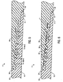
- Figure 5 is a side view of an embodiment of the threaded pipe joint connection wherein the width of the dove-tail thread increases in width along the helical length of the pin member.
- Figure 6 is a side view of an embodiment of the threaded pipe joint connection having a radial clearance between the mating crests and grooves of the intermediate and dove-tail threads.
- Figure 7 is a perspective view of a dove-tail thread as shown in Figure 5 having a gradually increasing width.
- Figure 8 is a side view of a threaded pipe connection according to another embodiment of the present invention.
- Figure 9 is a side view of an embodiment of the threaded pipe joint connection with hooked threads.
- Threaded tubular connections that are typically used in the production of oil and gas comprised of pins members that will be stabbed into box members that are designed to receive them.
- the connections are then made-up by applying torque to the connection.
- the pin and the box threads of each connection are typically machined on the same taper but the pin's tapered diameter is slightly larger than that of the box.
- a bearing pressure is generated between the mating surfaces of each pin and each box due to the axial movement of the pin into the box. This causes the pin to push the box radially outward, thus generating tangential hoop tension in the box, while at the same time, the box is pushing the pin inward generating hoop compression in the pin.
- connections have a generally dove-tail shaped thread form such that when the connection is made-up, hoop compression is produced in the box and hoop tension is produced in the pin.
- U.S. Patent 3,989,284, incorporated herein by reference, is an example of such dove-tail shaped threads.
- threaded connections would have ordinary torque capacity that is typical of such connections.
- some of the above mentioned designs will incorporate torque shoulders or wedge thread features. Whenever a wedge thread is used, the connection's torque resistance will be increased since excessive torque will result in axial squeezing on the threads which will prevent the pin from advancing any further in the box.
- U.S. Patent 3,989,284 discloses an example of threads which utilize this axial wedging feature.
- a threaded tubular connection embodying the present invention differs from other connections in the way the threads are profiled or arranged.
- a pipe joint 1 includes pin member 10 and box member 20.
- Interengaged thread means on the box and pin members include helical threads 12 and 15 extending along the length of pin member 10.
- Box member 20 includes helical mating threads 22 and 25 which are shaped and sized to mate with threads 12 and 15 respectively on pin member 10 during make-up of the connection.
- Threads 12 and 22 have a generally dove-tail shape and interfit such that during make-up of the box and pin members, flank 13 on thread 12 will engage flank 23 on thread 22, and opposite flank 14 on thread 12 will engage flank 24 on thread 22.
- flanks 13 and 23 and 14 and 24 will provide metal-to-metal seals along the thread length upon final make-up.
- Adjacent dove-tail threads 12 and 22 are intermediate threads 15 and 25 on the pin member and box member respectively.
- flank 17 of intermediate thread 15 will engage flank 27 of intermediate thread 25 and flank 18 of thread 15 will engage flank 28 of thread 25.
- Interengaged flanks 17 and 27 and 18 and 28 will also provide metal-to-metal seals along the thread length of the connection shown in Figure 1.
- dove-tail threads 12 have negative flank angles. Such flank angles should be less than about 85° to enable the interengaged flanks to resist unscrewing of the connection.
- Intermediate threads 15 have positive flank angles.
- the intermediate thread is a modified buttress thread.
- the intermediate thread may be a buttress thread, an ACME thread, a round thread or other conventional oilfield threads.
- opposing flanks on adjacent threads on pin member 10 are parallel, such as flank 14 on dove-tail thread 12 and flank 17 on intermediate thread 15.
- flank 18 of intermediate thread 15 is parallel to flank 13 of dove-tail thread 12.
- the opposing flanks of adjacent threads on box member 20 may also be parallel.
- the dual threads will be machined in a manner such that when the intermediate threads 15 and 25 begin to engage, they will generate hoop tension in the box and hoop compression in the pin.
- the dove-tail threads 12 and 22 begin to engage they will do the opposite, meaning they will generate hoop compression in the box and hoop tension in the pin.
- Torque is resisted by the radial interference and the opposing forces generated by the two different types of threads. Because the opposing forces offset one another, at least to some degree, the combined hoop stress acting on the connection is reduced, thus allowing more torque to be trapped in the connection. The more torque that can be applied to the connection, the higher the torque capacity and the higher the resistance to backing off downhole.
- the strain reactions to the torque are mainly radial.
- High torque is required to make-up the connection of the preferred embodiments.
- the resistance to make-up is due to the radial wedging created by the threads arrangement.
- External and/or internal shoulders may be used to improve sealing ability and to provide additional torque capacity.
- An external shoulder with a trapping angle is shown in Figure 1 where shoulder 34 of pin member 10 engages shoulder 36 of box member 20.
- the threads arrangement may also incorporate axial wedging to further increase the torque capacity of the connection.
- connection may have secondary sealing shoulders 37 and 38 on the pin nose 11 and back of box member 20 respectively. After primary sealing shoulders 34 and 36 have engaged, additional torque may be applied to the connection to close gap 41. Thus, the secondary seal shoulders 37 and 38 may be activated after a predetermined amount of torque has been applied to the connection. The reverse angle of shoulders 37 and 38 will keep pin nose 11 from extending radially into the internal diameter of the connection.
- the base widths of both the intermediate and dove-tail threads are constant along the helical length of both the box and pin members.
- the connection illustrated in Figures 1 and 2 are examples of such an embodiment.
- the dimensions of the dual threads may be configured to cause axial wedging between the mating threads on the box and pin members.
- One of skill will appreciate that there are various configurations, such as those described below, which will create such axial wedging.
- the base of the intermediate threads 25 on the box member 20 will have an equal width along the box thread length and the base of each intermediate thread 15 on the pin member 10 will have a width 15a that is slightly wider than the preceding intermediate thread's base as the threads move away from the pin nose 11 towards the outside diameter of tube 30.
- the base width of the intermediate thread 15 will gradually increase along the helical length of the thread.
- Figure 4 (as well as Figures 5 and 7) is shown with exaggerated dimensions to more clearly illustrate the described embodiment.
- the base width of intermediate thread 15 may increase by .0005 inches per thread along its helical length. This width may change depending on the subject pitch of the thread for any certain pipe diameter.
- the base width 12a of the dove-tail thread 12 increases along the helical length of the pin member while the base width of the mating dove-tail thread 22 remains the same.
- the box threads may have a slightly smaller width than that of the corresponding mating pin threads to create more interference and to create more rigidity and higher torque capacity.
- the width of the box threads may be .0005 inches per thread less than the corresponding mating pin threads.
- axially wedging may be obtained by having a constant base width for the intermediate threads of the pin member and box member but the base width of the mating thread on the box member is slightly smaller than the width of the corresponding thread on the pin member.
- axial wedging may be achieved by having the base width of the dove-tail thread on the box being slightly less than the mating dove-tail thread on the pin member.
- Thin wall tubular threaded connections usually do not have strong shoulders to give the connection a high torque capacity.
- the majority of the torque resistance is built into the threads of the connection and not in the shoulders thus giving thin wall connections a high torque capacity.
- An expander device such as a rotary expander, is introduced into the inside diameter of the pipe during the expansion procedure. As the expansion takes place, the rotating device tends to rotate the pin into the box. Without sufficient high torque resistance, the pin will over-rotate inside the box to a detrimental distance, thereby ruining the connection and possibly the pressure containing integrity of the wellbore.
- Tubular connections expanded by a non-rotating expanding means such as a solid cone or swedge, may try to lift apart due to the bending forces imparted on the connection as expansion proceeds along the length of the connection.
- a dual threaded connection embodying the present invention provides increased torque resistance to thread back off and thread jumping during axial or radial movement, thus allowing a higher percentage of expansion.
- a dual threaded connection embodying the present invention can be machined on plain end pipe, on upset ends or non-upset pins.
- the connection may be used as a coupled and threaded pipe connection, or as an integral pipe connection.
- box member 20 may be the box of an integral connection or one end of a coupling.
- the threaded pipe connection may be used on drill pipe tool joints, on casing, tubing, line pipe, wash pipe, completion tools and on other types of oilfield tubulars where a high torque capacity is needed.
- the threaded connection may be machined with a single lead, or a twin lead for faster make-up.
- a dual threaded connection embodying the present invention is machined with a twin lead.
- Figure 1 illustrates a resilient nonmetallic seal ring 57 located in a radial groove in box member 20.
- Seal ring 57 may be a Teflon® seal ring or an elastomeric seal ring.
- the connection may have a radial clearance or space between the mating crest and root of the intermediate and dove-tail threads for the box and pin member.
- Figure 6 shows radial clearance 32 between dove-tail threads 12 and 22 and radial clearance 35 between intermediate threads 15 and 25.
- Such radial clearance serves as an exit route for excess pipe dope during make-up and will contain the compressed thread compound after proper make-up to improve the threads sealing ability.
- the size of the space or gap may be selected to control or decrease the hoop stress generated by forcible make-up of the connection.
- the optimal radial clearance may be between about .002 inches and about .01 inches with a preferred clearance of about .004 inches.
- connection based on the application it is designed for, can produce a tubular threaded connection with performance properties that can match that of the tube. This can be done on upset or expanded integral joints and on threaded and coupled connections designs.
- connection can be machined on taper, straight or stepped.
- Figures 1, 2 and 3 illustrate examples of tapered, straight and stepped connections utilizing the present invention.
- the connections of an embodiment of the present invention may be machined with six threads per inch with a 1 1/8 inch taper per foot.
- thread pitch and the amount of taper or profile of the step as illustrated are not meant to be limiting and may vary without departing from the invention.
- Figure 8 illustrates a variation of an embodiment of the present invention which includes a recessed area 39 adjacent pin nose 11 when the connection is in the fully made-up position.
- Recess 39 allows the pin to expand into the recess during the expansion operation where the pin may tend to elongate and push against the back of the box. Couplings are known to have shrunk during the expansion operation.
- Figure 8 also shows an alternative embodiment of a radial metal-to-metal shoulder seal between shoulders 34 and 36.
- Ease of stabbing is a requirement in many applications. Such applications will include, but are not limited to wash pipe, liners, tubing, casing, drill pipe, etc. It is a very desirable feature in premium tubular connections.
- the threads adjacent to the intermediate threads are hooked threads instead of dove-tail threads. Hooked threads will also tend to generate compression hoop stress in the box and tensile hoop stress in the pin upon make-up and reduce the possibility of thread jump out due to heavy axial loads.
- the intermediate thread such as modified buttress threads, ACME threads, or round threads will do the opposite thus creating a situation where the combined hoop stress acting on the connection is reduced, thereby allowing more torque to be trapped in the connection.
- thread 42 has a negative (hooked) load angle (a) of about 10 degrees. Its stab angle (b) has a positive angle of about 45 degrees. Thread 45 has a positive load angle (c) of about 10 degrees and a stab angle (d) of about 45 degrees.
- the above angles arrangement is for demonstration purposes only and should not limit the use of other combination of different angles as long as one load angle is negative (hooked) and that the load angle for the adjacent thread is positive and that both the stab angles for both the adjacent threads are relatively steep angles ranging from about 25 to 50 degrees.
- the stab angles (b) and (d) preferably are equal, but embodiments with different stab angles may be used without departing from the invention.
- the load flank on thread 42 is negative and preferably between about 3 degrees and about 10 degrees.
- the stab angle for thread 42 is positive and preferably between about 30 degrees and about 45 degrees.
- Thread 45 preferably has a positive load flank between about 3 degrees and about 10 degrees and a stabbing flank having positive load angle between about 30 degrees and about 45 degrees. The optimum arrangement of the angles will give the designer a controlled range of hoop stress and a desired torque capacity.
- the dual thread arrangement as shown in Fig. 9, will generate hoop stresses in opposing directions due the engagement of mating threads. This arrangement will build a higher torque capacity in the connection and thus creating the need for higher make-up torque to fully make the connection.
Landscapes
- Engineering & Computer Science (AREA)
- General Engineering & Computer Science (AREA)
- Mining & Mineral Resources (AREA)
- Geology (AREA)
- Life Sciences & Earth Sciences (AREA)
- Mechanical Engineering (AREA)
- Environmental & Geological Engineering (AREA)
- Fluid Mechanics (AREA)
- Physics & Mathematics (AREA)
- General Life Sciences & Earth Sciences (AREA)
- Geochemistry & Mineralogy (AREA)
- Earth Drilling (AREA)
- Non-Disconnectible Joints And Screw-Threaded Joints (AREA)
- Mutual Connection Of Rods And Tubes (AREA)
Claims (36)
- Rohrschraubverbindung mit Box- und Stift-Teilen (20, 10) umfassend:ineinander eingreifbare Gewindemittel an den Box- und Stift-Teilen (20, 10), wobei das Gewinde Folgendes umfasst:ein Schwalbenschwanzgewinde (22, 12) mit negativen Flankenwinkeln, die entlang der Länge der Box- und Stift-Teile (20, 10) verlaufen, gekennzeichnet durchein Zwischengewinde (25, 15) mit positiven Flankenwinkeln, die entlang der Länge der Box- und Stift-Teile (20, 10) angrenzend am Schwalbenschwanzgewinde (22, 12) verlaufen;wobei das Zwischengewinde (25, 15) bei Verbindung des Stift-Teils (10) mit dem Box-Teil (20) eine Umfangsspannung im Box-Teil (20) und einen Umfangsdruck im Stift-Teil (10) und das Schwalbenschwanzgewinde (22, 12) einen Umfangsdruck im Box-Teil (20) und eine Umfangsspannung im Stift-Teil (10) erzeugt.
- Rohrschraubverbindung dadurch gekennzeichnet, dass sie Folgendes umfasst:ein Doppelgewinde-Stift-Teil (10) mit einem konischen, externen, allgemein schwalbenschwanzförmigen Gewinde (12) mit negativen Flankenwinkeln und einem konischen, externen Zwischengewinde (15) mit positiven Flankenwinkeln angrenzend am allgemein schwalbenschwanzförmigen Gewinde (12);ein Doppelgewinde-Box-Teil (20) mit einem konischen, internen, allgemein schwalbenschwanzförmigen dazu passenden Gewinde (22), das in das allgemein schwalbenschwanzförmige Gewinde (12) des Stift-Teils (10) eingreifen kann, und einem konischen, internen, dazu passenden Zwischengewinde (25), das in das Zwischengewinde (15) des Stift-Teils eingreifen kann, so dass das entsprechende allgemein schwalbenschwanzförmige Gewinde (12) und das Zwischengewinde (15) des Stift-Teils (10) in die entsprechenden dazu passenden Gewinde (22, 25) des Box-Teils (20) bei einer drehenden Bewegung zur Herstellung der Verbindung eingreifen kann.
- Rohrschraubverbindung nach Anspruch 1 oder 2, wobei die angrenzenden Flanken (14, 17; 13, 18) des Schwalbenschwanzgewindes und des Zwischengewindes parallel zueinander stehen.
- Rohrschraubverbindung nach Anspruch 1, 2 oder 3, wobei die Basisbreite des Zwischengewindes des Box-Teils im Wesentlichen die Gleiche entlang der Länge des Box-Teils ist.
- Rohrschraubverbindung nach einem der vorhergehenden Ansprüche, wobei die Basisbreite (15a) von jedem Zwischengewinde am Stift-Teil sich entlang der Länge des Stift-Teils allmählich vergrößert.
- Rohrschraubverbindung nach einem der vorhergehenden Ansprüche, wobei die Basisbreite des Schwalbenschwanzgewindes des Box-Teils im Wesentlichen die Gleiche entlang der Länge des Box-Teils ist.
- Rohrschraubverbindung nach einem der vorhergehenden Ansprüche, wobei die Basisbreite (12a) von jedem Schwalbenschwanzgewinde am Stift-Teil sich entlang der Länge des Stift-Teils allmählich vergrößert.
- Rohrschraubverbindung nach einem der vorhergehenden Ansprüche, wobei die Basisbreite (15a) des Zwischengewindes des Stift-Teils größer ist als die Basisbreite des dazu passenden Zwischengewindes des Box-Teils.
- Rohrschraubverbindung nach einem der vorhergehenden Ansprüche, wobei die Basisbreite (12a) des Schwalbenschwanzgewindes des Stift-Teils größer ist als die Basisbreite des dazu passenden Schwalbenschwanzgewindes des Box-Teils.
- Rohrschraubverbindung nach einem der vorhergehenden Ansprüche, wobei das Zwischengewinde ein modifiziertes Sägezahngewinde ist.
- Rohrschraubverbindung nach einem der vorhergehenden Ansprüche, wobei das Zwischengewinde ein Sägezahngewinde, ACME-Gewinde oder Rundgewinde ist.
- Rohrschraubverbindung nach einem der vorhergehenden Ansprüche, wobei das Zwischengewinde einem Zurückdrehen bei radialer Ausdehnung der Verbindung widersteht.
- Rohrschraubverbindung nach einem der vorhergehenden Ansprüche, wobei das Box-Teil und das Stift-Teil ein gestuftes Profil aufweisen.
- Rohrschraubverbindung nach einem der vorhergehenden Ansprüche, wobei die Rohrschraubverbindung Bohrgestänge-, Verrohrungs-, Schacht- oder Schutzrohrverbindungen verbindet.
- Rohrschraubverbindung nach einem der vorhergehenden Ansprüche, ferner umfassend ein Radialspiel (35) für Dichtungskitt zwischen der Gewindespitze des Zwischengewindes am Stift-Teil und dem Gewindegrund des Zwischengewindes am Box-Teil.
- Rohrschraubverbindung nach einem der vorhergehenden Ansprüche, ferner umfassend ein Radialspiel (32) für Dichtungskitt zwischen der Gewindespitze des Schwalbenschwanzgewindes am Stift-Teil und dem Gewindegrund des Schwalbenschwanzgewindes am Box-Teil.
- Rohrschraubverbindung nach einem der vorhergehenden Ansprüche, ferner umfassend einen flexiblen Dichtring (57) im Box-Teil.
- Rohrschraubverbindung nach Anspruch 17, wobei der Dichtring ein Teflon®-Dichtring ist.
- Rohrschraubverbindung nach Anspruch 17 oder 18, wobei der Dichtring ein elastomerischer Dichtring ist.
- Rohrschraubverbindung nach einem der vorhergehenden Ansprüche, ferner umfassend eine negative Schulterdichtung zwischen dem Stift-Teil und dem Box-Teil.
- Rohrschraubverbindung nach einem der vorhergehenden Ansprüche, wobei die Verbindung gestaucht oder nicht gestaucht sein kann.
- Rohrschraubverbindung nach einem der vorhergehenden Ansprüche, ferner umfassend Metall/Metall-Dichtungen zwischen den zueinander passenden Flanken des Schwalbenschwanzgewindes an den Box- und Stift-Teilen.
- Rohrschraubverbindung nach einem der vorhergehenden Ansprüche, ferner umfassend Metall/Metall-Dichtungen zwischen den zueinander passenden Flanken des Zwischengewindes an den Box- und Stift-Teilen.
- Rohrschraubverbindung nach einem der vorhergehenden Ansprüche, ferner umfassend ein Radialspiel für Dichtungskitt zwischen der Gewindespitze des Zwischengewindes und dem Schwalbenschwanzgewinde am Stift-Teil und dem Gewindegrund des Zwischengewindes und dem Schwalbenschwanzgewinde am Box-Teil.
- Rohrschraubverbindung nach einem der vorhergehenden Ansprüche, ferner umfassend eine Doppelführung zum Beginnen des Eingriffs zwischen dem Stift-Teil und dem Box-Teil.
- Rohrverbindung mit einem Box-Teil und einem Stift-Teil (20, 10) mit ineinander eingreifbaren Gewinden umfassend:ein erstes Gewinde (22, 12; 42) mit einem negativen Belastungswinkel (a), der beim Herstellen der Verbindung einen Umfangsdruck im Box-Teil (20) und eine Umfangsspannung im Stift-Teil (10) erzeugt; gekennzeichnet durchein zweites Gewinde (25, 15; 45) angrenzend am ersten Gewinde (22, 12; 42) mit einem positiven Belastungswinkel (c), der beim Herstellen der Verbindung eine Umfangsspannung im Box-Teil (20) und einen Umfangsdruck im Stift-Teil (10) erzeugt.
- Rohrverbindung nach Anspruch 26, wobei das erste Gewinde allgemein schwalbenschwanzförmig ist.
- Rohrverbindung nach Anspruch 26 oder 27, wobei das erste Gewinde einen positiven Einführungswinkel (b) aufweist.
- Rohrverbindung nach Anspruch 28, wobei der positive Einführungswinkel (b) einen Winkel zwischen etwa 30° und etwa 45° aufweist.
- Rohrverbindung nach einem der vorhergehenden Ansprüche 26 bis 29, wobei der negative Belastungswinkel (a) einen Winkel zwischen etwa 3° und etwa 10° aufweist.
- Rohrverbindung nach einem der vorhergehenden Ansprüche 26 bis 30, wobei die ineinander eingreifbaren Gewinde ein Reservoir für Dichtungskitt aufweisen, umfassend ein radiales Spiel zwischen den zueinander passenden Spitzen und Wurzeln des ersten und zweiten Gewindes an den Box- und Stift-Teilen.
- Rohrverbindung nach einem der vorhergehenden Ansprüche 26 bis 31, wobei das zweite Gewinde am Stift-Teil so konfiguriert ist, dass es eine axiale Verkeilung mit dem ineinander eingreifbaren zweiten Gewinde am Box-Teil erzeugt.
- Rohrverbindung nach einem der vorhergehenden Ansprüche 26 bis 32, wobei das erste Gewinde am Stift-Teil so konfiguriert ist, dass es eine axiale Verkeilung mit dem ineinander eingreifbaren ersten Gewinde am Box-Teil erzeugt.
- Rohrverbindung nach einem der vorhergehenden Ansprüche 26 bis 33, wobei die gegenüberliegenden Umfangsbelastungen, die durch das erste und zweite Gewinde erzeugt werden, die kombinierte Umfangsbelastung, die auf der Verbindung lastet, reduziert.
- Rohrverbindung nach einem der vorhergehenden Ansprüche 26 bis 34, wobei das zweite Gewinde ein Sägezahngewinde, eine ACME-Gewinde oder ein Rundgewinde ist.
- Rohrverbindung nach einem der vorhergehenden Ansprüche 26 bis 35, wobei nach Herstellung der Verbindung das erste Gewinde eine axiale und radiale Verkeilung entlang der Länge der Verbindung erzeugt.
Applications Claiming Priority (3)
| Application Number | Priority Date | Filing Date | Title |
|---|---|---|---|
| US10/095,124 US6767035B2 (en) | 2002-03-11 | 2002-03-11 | High torque modified profile threaded tubular connection |
| US95124 | 2002-03-11 | ||
| PCT/GB2003/000790 WO2003078882A1 (en) | 2002-03-11 | 2003-02-25 | High torque modified profile threaded tubular connection |
Publications (2)
| Publication Number | Publication Date |
|---|---|
| EP1483520A1 EP1483520A1 (de) | 2004-12-08 |
| EP1483520B1 true EP1483520B1 (de) | 2006-12-27 |
Family
ID=27788197
Family Applications (1)
| Application Number | Title | Priority Date | Filing Date |
|---|---|---|---|
| EP03704815A Expired - Lifetime EP1483520B1 (de) | 2002-03-11 | 2003-02-25 | Rohrförmige schraubverbindung mit hohem drehmoment und mit einem modifiziertem schraubprofil |
Country Status (6)
| Country | Link |
|---|---|
| US (1) | US6767035B2 (de) |
| EP (1) | EP1483520B1 (de) |
| AU (1) | AU2003207343A1 (de) |
| CA (1) | CA2452756C (de) |
| DE (1) | DE60310688T2 (de) |
| WO (1) | WO2003078882A1 (de) |
Families Citing this family (54)
| Publication number | Priority date | Publication date | Assignee | Title |
|---|---|---|---|---|
| US7125053B2 (en) * | 2002-06-10 | 2006-10-24 | Weatherford/ Lamb, Inc. | Pre-expanded connector for expandable downhole tubulars |
| US6971685B2 (en) * | 2002-06-24 | 2005-12-06 | Weatherford/Lamb, Inc. | Multi-point high pressure seal for expandable tubular connections |
| GB0215668D0 (en) * | 2002-07-06 | 2002-08-14 | Weatherford Lamb | Coupling tubulars |
| GB0221220D0 (en) * | 2002-09-13 | 2002-10-23 | Weatherford Lamb | Expanding coupling |
| GB0221585D0 (en) * | 2002-09-17 | 2002-10-23 | Weatherford Lamb | Tubing connection arrangement |
| GB0222321D0 (en) * | 2002-09-25 | 2002-10-30 | Weatherford Lamb | Expandable connection |
| US6997264B2 (en) * | 2002-10-10 | 2006-02-14 | Weatherford/Lamb, Inc. | Method of jointing and running expandable tubulars |
| US6981547B2 (en) * | 2002-12-06 | 2006-01-03 | Weatherford/Lamb, Inc. | Wire lock expandable connection |
| US7025135B2 (en) * | 2003-05-22 | 2006-04-11 | Weatherford/Lamb, Inc. | Thread integrity feature for expandable connections |
| US7887103B2 (en) | 2003-05-22 | 2011-02-15 | Watherford/Lamb, Inc. | Energizing seal for expandable connections |
| GB0311721D0 (en) * | 2003-05-22 | 2003-06-25 | Weatherford Lamb | Tubing connector |
| CA2552722C (en) * | 2004-01-12 | 2012-08-07 | Shell Oil Company | Expandable connection |
| GB0413998D0 (en) * | 2004-06-23 | 2004-07-28 | Pedem Ltd | Connection apparatus and method |
| US20060071473A1 (en) * | 2004-10-05 | 2006-04-06 | Sivley Robert S Iv | Helical groove for a tubular connection |
| US7717478B2 (en) * | 2006-08-29 | 2010-05-18 | Hydril Llc | Scalloped wedge threads |
| US7798536B2 (en) * | 2005-08-11 | 2010-09-21 | Weatherford/Lamb, Inc. | Reverse sliding seal for expandable tubular connections |
| US7591059B2 (en) * | 2005-09-13 | 2009-09-22 | Weatherford/Lamb, Inc. | Expansion activated anti-rotation device |
| US20100230958A1 (en) * | 2005-09-28 | 2010-09-16 | Enventure Global Technology, L.L.C. | Method and Apparatus for coupling Expandable Tubular Members |
| WO2007047193A2 (en) * | 2005-10-11 | 2007-04-26 | Enventure Global Technology, L.L.C. | Method and apparatus for coupling expandable tubular members |
| US7475917B2 (en) * | 2006-03-30 | 2009-01-13 | Hydril Company | Threaded connection with variable flank angles |
| US7686350B2 (en) * | 2006-03-30 | 2010-03-30 | Hydril Llc | Mismatched flanks for a wedge thread |
| US7615077B2 (en) * | 2006-03-31 | 2009-11-10 | Warsaw Orthopedic, Inc. | Intervertebral implants with radial teeth and methods of use |
| US20070257486A1 (en) * | 2006-05-03 | 2007-11-08 | Grinaldi Ltd. | Elastomeric Seal for Expandable Connector |
| FR2917805B1 (fr) † | 2007-06-25 | 2009-09-04 | Vallourec Mannesmann Oil & Gas | Element filete de composant a filetage antagonistes, et joint filete tubulaire correspondant |
| US20100052319A1 (en) * | 2008-08-28 | 2010-03-04 | Mohawk Energy Ltd. | Dual Seal Expandable Tubular Connection |
| US20100132956A1 (en) * | 2008-12-01 | 2010-06-03 | Enventure Global Technology, L.L.C. | Expandable connection with metal to metal seal |
| SE534883C2 (sv) * | 2009-03-26 | 2012-01-31 | Sandvik Intellectual Property | Del hos ett förband i ett tunnväggigt borrör, förbandssystem och tunnväggigt borrörssystem. |
| CN101696621B (zh) * | 2009-11-04 | 2012-05-16 | 天津钢管集团股份有限公司 | 气密封螺纹接头 |
| US10066656B2 (en) * | 2011-11-22 | 2018-09-04 | Lock-N-Stitch, Inc. | Threaded fastener having a thread crest greater than its thread root and “V” angles on the crest and root |
| WO2013101852A1 (en) * | 2011-12-27 | 2013-07-04 | Watts John Dawson | High torque threaded pipe connection |
| CH706013A1 (de) * | 2012-01-11 | 2013-07-15 | Kistler Holding Ag | Sensorpaket für WIM Sensor und WIM Sensor. |
| WO2013124386A1 (en) | 2012-02-23 | 2013-08-29 | Shell Internationale Research Maatschappij B.V. | Connector assembly |
| WO2013163592A1 (en) * | 2012-04-27 | 2013-10-31 | Axon Ep, Inc. | Flexible connections |
| CA2874384A1 (en) * | 2012-06-15 | 2013-12-19 | Daniele DI CRESCENZO | Method and connector assembly for connecting tubular members |
| US9677346B2 (en) * | 2012-11-28 | 2017-06-13 | Ultra Premium Oilfield Services, Ltd. | Tubular connection with helically extending torque shoulder |
| US9677179B2 (en) | 2012-12-20 | 2017-06-13 | Shell Oil Company | Pipe connector and method |
| US9568120B2 (en) | 2012-12-31 | 2017-02-14 | North American Specialty Products Llc | Flush joint pipe |
| CN104060946A (zh) * | 2013-03-21 | 2014-09-24 | 宝山钢铁股份有限公司 | 超高抗扭金属气密封钻杆接头 |
| FR3014534B1 (fr) | 2013-12-10 | 2015-12-04 | Vallourec Oil & Gas France | Ensemble pour la realisation d'un joint filete pour le forage et l'exploitation des puits d'hydrocarbures et joint filete resultant |
| GB2527109A (en) * | 2014-06-12 | 2015-12-16 | Meta Downhole Ltd | Pipe coupling |
| US10801273B2 (en) | 2014-11-24 | 2020-10-13 | Halliburton Energy Services, Inc. | Friction based thread lock for high torque carrying connections |
| US10309198B2 (en) | 2015-01-05 | 2019-06-04 | Morph Packers Limited | Pipe coupling |
| WO2016112451A1 (en) | 2015-01-12 | 2016-07-21 | Halliburton Energy Services, Inc. | Connection for transmitting torque and axial forces |
| US10041307B2 (en) | 2015-01-22 | 2018-08-07 | National Oilwell Varco, L.P. | Balanced thread form, tubulars employing the same, and methods relating thereto |
| EP3128119A1 (de) | 2015-08-05 | 2017-02-08 | Hydril Company | Rohrverschraubung |
| US9683684B1 (en) | 2015-12-09 | 2017-06-20 | Certus Energy Solutions, Llc | Tubular coupling |
| US11466800B2 (en) | 2015-12-09 | 2022-10-11 | Certus Energy Solutions, Llc | Tubular coupling |
| NL2018298B1 (en) * | 2017-02-03 | 2018-08-28 | Hydril Co | Threaded tubular connection |
| WO2018216375A1 (ja) * | 2017-05-25 | 2018-11-29 | 新日鐵住金株式会社 | 鋼管用ねじ継手 |
| US11382724B2 (en) | 2017-10-11 | 2022-07-12 | Evollution Ip Holdings, Inc. | Three-dimensional stabilization thread form for dental implants |
| WO2019210021A1 (en) | 2018-04-25 | 2019-10-31 | Hydril Company | Wedge thread connection for tubular goods |
| US11204115B2 (en) * | 2018-07-20 | 2021-12-21 | National Oilwell Varco, L.P. | Threaded connections for tubular members |
| CA3195667A1 (en) * | 2020-09-16 | 2022-03-24 | Dale E. Van Cor | Key thread and key thread systems |
| WO2023055892A1 (en) * | 2021-09-29 | 2023-04-06 | Cooper Larry V | Threaded connection for tubular pipes |
Family Cites Families (26)
| Publication number | Priority date | Publication date | Assignee | Title |
|---|---|---|---|---|
| US3989284A (en) | 1975-04-23 | 1976-11-02 | Hydril Company | Tubular connection |
| US4244607A (en) * | 1979-01-02 | 1981-01-13 | Hydril Company | Cylindrical threaded connection |
| US4917409A (en) * | 1983-04-29 | 1990-04-17 | Hydril Company | Tubular connection |
| DE3480945D1 (de) | 1983-04-29 | 1990-02-08 | Baker Hughes Inc | Mit einer unilateralen dichtung versehene schraubverbindung. |
| US4600224A (en) * | 1983-12-23 | 1986-07-15 | Interlock Technologies Corporation | Tubular connection having a chevron wedge thread |
| US4648627A (en) | 1984-01-18 | 1987-03-10 | Dril-Quip, Inc. | Stabbing connector |
| US4703959A (en) | 1986-02-10 | 1987-11-03 | Hydril Company | Threaded pipe connection with compressible seal ring |
| US4707001A (en) | 1986-06-20 | 1987-11-17 | Seal-Tech, Inc. | Liner connection |
| US5427418A (en) | 1986-07-18 | 1995-06-27 | Watts; John D. | High strength, low torque threaded tubular connection |
| JPH0631661B2 (ja) * | 1987-02-23 | 1994-04-27 | 新日本製鐵株式会社 | 低応力・高気密油井管用ネジ継手 |
| US4822081A (en) * | 1987-03-23 | 1989-04-18 | Xl Systems | Driveable threaded tubular connection |
| US5360240A (en) * | 1993-03-05 | 1994-11-01 | Hydril Company | Method of connecting plastic pipe joints to form a liner for an existing pipeline and a plastic pipe joint for forming such liner |
| US5415441A (en) | 1994-02-28 | 1995-05-16 | Halliburton Company | Push-on coupling apparatus for tubular well completion structures |
| GB9510465D0 (en) | 1995-05-24 | 1995-07-19 | Petroline Wireline Services | Connector assembly |
| JP2000501805A (ja) | 1995-12-09 | 2000-02-15 | ペトロライン ウェルシステムズ リミテッド | 管材コネクター |
| GB9608709D0 (en) | 1996-04-26 | 1996-07-03 | Hunting Oilfield Services Ltd | Improvements in and relating to pipe connectors |
| US6789822B1 (en) | 1997-03-21 | 2004-09-14 | Weatherford/Lamb, Inc. | Expandable slotted tubing string and method for connecting such a tubing string |
| US6050610A (en) * | 1997-05-20 | 2000-04-18 | Hydril Company | Stress reduction groove for tubular connection |
| US6042153A (en) | 1998-02-25 | 2000-03-28 | Grant Prideco, Inc. | Threaded connection for internally clad pipe |
| US6174001B1 (en) * | 1998-03-19 | 2001-01-16 | Hydril Company | Two-step, low torque wedge thread for tubular connector |
| US6123368A (en) | 1998-03-19 | 2000-09-26 | Hydril Company | Two-step, differential diameter wedge threaded connector |
| US6206436B1 (en) * | 1999-02-19 | 2001-03-27 | Hydril Company | Differential wedge thread for threaded connector |
| US6254146B1 (en) * | 1999-04-23 | 2001-07-03 | John Gandy Corporation | Thread form with multifacited flanks |
| CA2306656C (en) | 1999-04-26 | 2006-06-06 | Shell Internationale Research Maatschappij B.V. | Expandable connector for borehole tubes |
| US6409175B1 (en) | 1999-07-13 | 2002-06-25 | Grant Prideco, Inc. | Expandable joint connector |
| US6554287B1 (en) | 1999-12-09 | 2003-04-29 | Hydril Company | Collapsing type seal for expandable tubular connections |
-
2002
- 2002-03-11 US US10/095,124 patent/US6767035B2/en not_active Expired - Lifetime
-
2003
- 2003-02-25 AU AU2003207343A patent/AU2003207343A1/en not_active Abandoned
- 2003-02-25 DE DE60310688T patent/DE60310688T2/de not_active Expired - Lifetime
- 2003-02-25 CA CA002452756A patent/CA2452756C/en not_active Expired - Fee Related
- 2003-02-25 WO PCT/GB2003/000790 patent/WO2003078882A1/en active IP Right Grant
- 2003-02-25 EP EP03704815A patent/EP1483520B1/de not_active Expired - Lifetime
Also Published As
| Publication number | Publication date |
|---|---|
| CA2452756C (en) | 2007-11-20 |
| DE60310688T2 (de) | 2007-10-11 |
| EP1483520A1 (de) | 2004-12-08 |
| US6767035B2 (en) | 2004-07-27 |
| DE60310688D1 (de) | 2007-02-08 |
| AU2003207343A1 (en) | 2003-09-29 |
| WO2003078882A1 (en) | 2003-09-25 |
| CA2452756A1 (en) | 2003-09-25 |
| US20030168858A1 (en) | 2003-09-11 |
Similar Documents
| Publication | Publication Date | Title |
|---|---|---|
| EP1483520B1 (de) | Rohrförmige schraubverbindung mit hohem drehmoment und mit einem modifiziertem schraubprofil | |
| US6322110B1 (en) | Tubular connection | |
| JP3210021B2 (ja) | 非ダブテール型かみ合いクサビ状ネジ山を有する管連結部 | |
| AU2008251935B2 (en) | Thread form for tubular connections | |
| EP1836426B1 (de) | Zweistufige pseudo-verbindung | |
| KR102020094B1 (ko) | 나선형으로 연장하는 토크 숄더를 갖는 관형 연결부 | |
| EP2452111B1 (de) | Pfeilförmige gewindeform mit röhrenverbindungen | |
| AU2003246324A1 (en) | Expandable Coupling | |
| US7588269B2 (en) | Z-shaped thread form for tubular connections | |
| GB2547469A (en) | Tubular connection with helically extending torque shoulder | |
| EP1482124B1 (de) | Nicht rotierende erweiterbare Verbindung mit verformbarer Dichtung | |
| US12066130B2 (en) | Threaded connection partially in a self-locking engagement with an external shoulder capable to resist elevated torque |
Legal Events
| Date | Code | Title | Description |
|---|---|---|---|
| PUAI | Public reference made under article 153(3) epc to a published international application that has entered the european phase |
Free format text: ORIGINAL CODE: 0009012 |
|
| 17P | Request for examination filed |
Effective date: 20040113 |
|
| AK | Designated contracting states |
Kind code of ref document: A1 Designated state(s): DE FR GB NL |
|
| AX | Request for extension of the european patent |
Extension state: AL LT LV MK RO |
|
| 17Q | First examination report despatched |
Effective date: 20050525 |
|
| GRAP | Despatch of communication of intention to grant a patent |
Free format text: ORIGINAL CODE: EPIDOSNIGR1 |
|
| GRAS | Grant fee paid |
Free format text: ORIGINAL CODE: EPIDOSNIGR3 |
|
| GRAA | (expected) grant |
Free format text: ORIGINAL CODE: 0009210 |
|
| AK | Designated contracting states |
Kind code of ref document: B1 Designated state(s): DE FR GB NL |
|
| REG | Reference to a national code |
Ref country code: GB Ref legal event code: FG4D |
|
| REF | Corresponds to: |
Ref document number: 60310688 Country of ref document: DE Date of ref document: 20070208 Kind code of ref document: P |
|
| ET | Fr: translation filed | ||
| PLBE | No opposition filed within time limit |
Free format text: ORIGINAL CODE: 0009261 |
|
| STAA | Information on the status of an ep patent application or granted ep patent |
Free format text: STATUS: NO OPPOSITION FILED WITHIN TIME LIMIT |
|
| 26N | No opposition filed |
Effective date: 20070928 |
|
| REG | Reference to a national code |
Ref country code: NL Ref legal event code: SD Effective date: 20150318 |
|
| REG | Reference to a national code |
Ref country code: DE Ref legal event code: R081 Ref document number: 60310688 Country of ref document: DE Owner name: WEATHERFORD TECHNOLOGY HOLDINGS, LLC, HOUSTON, US Free format text: FORMER OWNER: WEATHERFORD/LAMB, INC., HOUSTON, TEX., US Effective date: 20150417 |
|
| REG | Reference to a national code |
Ref country code: FR Ref legal event code: TP Owner name: WEATHERFORD TECHNOLOGY HOLDINGS, LLC, US Effective date: 20150603 |
|
| REG | Reference to a national code |
Ref country code: GB Ref legal event code: 732E Free format text: REGISTERED BETWEEN 20151029 AND 20151104 |
|
| REG | Reference to a national code |
Ref country code: FR Ref legal event code: PLFP Year of fee payment: 14 |
|
| PGFP | Annual fee paid to national office [announced via postgrant information from national office to epo] |
Ref country code: DE Payment date: 20160216 Year of fee payment: 14 |
|
| PGFP | Annual fee paid to national office [announced via postgrant information from national office to epo] |
Ref country code: FR Payment date: 20160108 Year of fee payment: 14 Ref country code: NL Payment date: 20160210 Year of fee payment: 14 Ref country code: GB Payment date: 20160224 Year of fee payment: 14 |
|
| REG | Reference to a national code |
Ref country code: DE Ref legal event code: R119 Ref document number: 60310688 Country of ref document: DE |
|
| REG | Reference to a national code |
Ref country code: NL Ref legal event code: MM Effective date: 20170301 |
|
| GBPC | Gb: european patent ceased through non-payment of renewal fee |
Effective date: 20170225 |
|
| PG25 | Lapsed in a contracting state [announced via postgrant information from national office to epo] |
Ref country code: NL Free format text: LAPSE BECAUSE OF NON-PAYMENT OF DUE FEES Effective date: 20170301 |
|
| REG | Reference to a national code |
Ref country code: FR Ref legal event code: ST Effective date: 20171031 |
|
| PG25 | Lapsed in a contracting state [announced via postgrant information from national office to epo] |
Ref country code: FR Free format text: LAPSE BECAUSE OF NON-PAYMENT OF DUE FEES Effective date: 20170228 Ref country code: DE Free format text: LAPSE BECAUSE OF NON-PAYMENT OF DUE FEES Effective date: 20170901 |
|
| PG25 | Lapsed in a contracting state [announced via postgrant information from national office to epo] |
Ref country code: GB Free format text: LAPSE BECAUSE OF NON-PAYMENT OF DUE FEES Effective date: 20170225 |