EP2452111B1 - Pfeilförmige gewindeform mit röhrenverbindungen - Google Patents
Pfeilförmige gewindeform mit röhrenverbindungen Download PDFInfo
- Publication number
- EP2452111B1 EP2452111B1 EP10797659.9A EP10797659A EP2452111B1 EP 2452111 B1 EP2452111 B1 EP 2452111B1 EP 10797659 A EP10797659 A EP 10797659A EP 2452111 B1 EP2452111 B1 EP 2452111B1
- Authority
- EP
- European Patent Office
- Prior art keywords
- thread
- flanks
- facets
- threads
- stab
- Prior art date
- Legal status (The legal status is an assumption and is not a legal conclusion. Google has not performed a legal analysis and makes no representation as to the accuracy of the status listed.)
- Active
Links
Images
Classifications
-
- F—MECHANICAL ENGINEERING; LIGHTING; HEATING; WEAPONS; BLASTING
- F16—ENGINEERING ELEMENTS AND UNITS; GENERAL MEASURES FOR PRODUCING AND MAINTAINING EFFECTIVE FUNCTIONING OF MACHINES OR INSTALLATIONS; THERMAL INSULATION IN GENERAL
- F16L—PIPES; JOINTS OR FITTINGS FOR PIPES; SUPPORTS FOR PIPES, CABLES OR PROTECTIVE TUBING; MEANS FOR THERMAL INSULATION IN GENERAL
- F16L15/00—Screw-threaded joints; Forms of screw-threads for such joints
- F16L15/06—Screw-threaded joints; Forms of screw-threads for such joints characterised by the shape of the screw-thread
-
- E—FIXED CONSTRUCTIONS
- E21—EARTH OR ROCK DRILLING; MINING
- E21B—EARTH OR ROCK DRILLING; OBTAINING OIL, GAS, WATER, SOLUBLE OR MELTABLE MATERIALS OR A SLURRY OF MINERALS FROM WELLS
- E21B17/00—Drilling rods or pipes; Flexible drill strings; Kellies; Drill collars; Sucker rods; Cables; Casings; Tubings
- E21B17/02—Couplings; joints
- E21B17/04—Couplings; joints between rod or the like and bit or between rod and rod or the like
- E21B17/042—Threaded
Definitions
- the present invention relates to a thread form for threaded connections of the type used for securing tubular flow conduits to form a desired continuous flow path.
- a variety of threaded connections are known in the prior art for joining tubular flow conduits in an end-to-end relationship to form a continuous flow path for transporting fluid.
- Typical examples of such flow conduits include casing, expandable casing, tubing, drill pipe and risers for oil, gas, water and waste disposal wells, and in horizontal and trenchless drilling applications.
- oil field casing and tubing it is a common practice to use metal pipes of a definite length, with sections of pipe joined to form a string.
- the string of pipes effectively creates one lengthier pipe, intended to provide a means to reach the depth at which the reservoirs of gas or oil are found in order for extraction to the surface.
- the pipe sections are secured together at their ends by an externally threaded connector, or "pin” that is threadedly received within an internally threaded connector or “box".
- Each pipe section has a pin on one pipe end and a box at the opposite pipe end.
- Some pipe has an internally threaded coupling secured to one end of a double pin pipe section to produce the box.
- the individual pipe sections are frequently referred to as a "pipe joint".
- Tubing and casing pipe joints are usually 30 ft. in length but can vary in length from 20 ft. to 40 ft. or longer.
- the various pipe strings used in constructing a well are usually assembled on the floor of a drilling or workover rig.
- the pipe string is lengthened and lowered into the well as succeeding pipe joints are added to the string.
- the pipe joint being added to the string is lowered, pin down or pin up, into an upwardly or downwardly facing box projecting from the drilling rig floor. This procedure is commonly referred to as "stabbing" the pin into the box.
- the added pipe joint is rotated to engage the threads of the pin and box, securing the joint to the string.
- the process is basically reversed in or to disassemble the pipe string. Once free of the box, the removed joint is moved to a storage location.
- Re. Pat. No. 34,467 issued Dec. 7, 1992 to Reeves purported to be an improvement to the basic Blose wedge thread design.
- incompressible thread lubricant orother liquid may be trapped between the engaged load flanks.
- This trapped thread lubricant can resist the make-up torque and give a false torque indication that results in lower than desired stress and strain being induced in the Blose connection and reducing the design strength and load carrying capacity.
- the invention described in Re. Pat. No. 34,467 purports to preclude the possibility of false indication of torque by excluding thread lubricant from between the thread load flanks that are brought into engagement at make-up.
- the stab flanks complex profile is preferably a multi-faceted flank having at least three facets and four radii per stab flank.
- the pin thread crests have a crest width and the pin roots have a root width.
- the width of the crest is less than the width of the roots, which is exactly opposite that of the general dovetail design.
- the present invention has as its object to provide a further modification of the basic thread forms discussed above which provides improved design characteristics and performance over the prior art.
- the thread forms of the invention can be used for making a threaded pipe connection capable of being screwed together and subsequently unscrewed.
- the thread forms are used on a connection which includes a pin having external threads with stab flanks and load flanks and flat crests and roots for mating with the mating internal threads of a box to make up a pipe connection.
- the thread forms of the invention have a specially designed profile interfit between the two mating thread surfaces of the threaded connection. This specially designed profile is present on both the stab flank and the load flank of the threads making up the thread form.
- the pin stab flanks and load flanks are each comprised of two facets.
- the facets on the stab flanks and the corresponding facets on the load flanks of each thread both lean in the same direction in imaginary parallel planes, so that the facets form an arrow-shape when viewed in profile.
- the facets which make up the stab flank and load flank each have a defined facet height when measured with respect to the thread roots.
- the facet heights when combined together, form the overall flank height for the particular flank under consideration.
- the facet heights are approximately equal.
- the facet heights may differ.
- the facet height of one of the stab or load flank facets adjacent the thread roots can be greater than the remaining facet heights of the particular thread.
- the preferred thread forms can be formed with a negatively sloped facet which forms a hook at the base of the load flank to provide tensile load capabilities only afforded by a negative load flank angle thread form.
- the thread form of the invention can be provided with tapered threads having a given angle of taper with respect to a longitudinal axis of the pipe.
- the thread form can be provided with parallel threads where thread roots and crests are parallel to the longitudinal axis of the pipe.
- the thread form can also be provided with threads which are helically structured as a wedge.
- the threads of the invention can be used to form a secure tubular connection which can be used with a tubular selected from the group consisting of oil, gas, construction, water and waste disposal well casing and tubing.
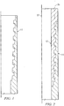
- Figure 1 of the drawings there is shown a quarter, cross-sectional view of a box end of a section of tubular pipe, such as a section of oil field casing, employing the thread form of the invention, the section of pipe being designed generally as 11.
- Figure 2 of the drawings is a similar quarter, cross-sectional view, but showing the box end 11 being made up with a mating pin end 12 to form the threaded pipe connection.
- the thread forms of the invention can also be applied to a wide variety of tubular goods.
- Typical applications could include, but are not limited to, oil and gas offshore and onshore sub surface casing, intermediate casing, production casing, expandable casing, work over tubing, production tubing, tiebacks, risers, pile driving casing, line pipe, drill pipe, TNT pipe, flush joints, HDD pipe, water well pipe, liners for constructions, mining pipe, and disposal wells.
- the thread forms of the invention can be used in a variety of known types of pipe connections, including connections which are swaged, expanded, upset or non-upset and can be tapered or "cylindrical", non-tapered connections.
- the thread forms of the invention can also be used in connections which are helically structured as wedge threads such as those described in Blose Re. Pat. No. 30,647 and Reeves Re. Pat. No. 34,467 .
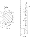
- Figure 3 shows one isolated thread from the box end of Figure 1 in section and in greater detail.
- the box end 11 of the tubular member has pin threads with thread crests 13 and thread roots 15.
- the crests 13 and roots 15 of the box member 11 are adapted to be made up with a mating pin member (illustrated as 12 in Figure 2 ), having a complimentary thread structure.
- the pin end is essentially a mirror image of the box end.
- the box thread crests 13 are formed between a stab flank 17 and a load flank 19 of the pin thread (see Figure 3 ).
- the thread crests 13 are approximately parallel to the thread roots 15.
- load flank will be understood to designate that sidewall of a thread that faces away from the outer end from the respective male or female member on which the thread is formed
- stab flank will be understood to refer to that sidewall surface that faces toward the outer end of the respective male or female member as the connection is made up.
- the box mouth or outer end would be located toward the top of the drawing.
- the stab flanks 17 and load flanks 19 of the thread form of the invention are each designed to form a specially designed interfit between the two mating thread surfaces of the pin end and box end of the threaded connection.
- This specially designed profile interfit is present on both the stab flank 17 and the load flank 19 of the threads making up the thread form.
- the stab flanks 17 and load flanks 19 are each comprised of only two facets, 21, 23 and 25, 27, respectively.
- the facet 23 forms a negative angle or "hook” with respect to the thread root 15 and to the horizontal axis of the pipe string (illustrated as 37 in Figure 2 ).
- negative angle is meant that the angle formed between the facet 23 and the adjacent thread root surface 15 is an acute angle whereby the facet 23 flares or leans inwardly toward the thread root 15.
- the facet 21 forms a positive angle with respect to the surface 15.
- the facets 21 and 25 are all inclined in the same direction while the facets 23 and 27 are all inclined in the same direction.
- the facets 21 and 25 are parallel and the facets 23 and 27 are parallel, it will be appreciated that the respective flanks could have facets which are not perfectly parallel, as well, as long as they continue to lean in the same general direction.
- the unique profile interfit of the stab and load flanks of the thread form of the invention differs from, for example, a traditional "dovetail" thread.
- the stab and load flanks flare outwardly in opposite directions from the longitudinal axis of the pipe and from the thread roots.
- the thread crests of the traditional dovetail are also wider than the width of the thread at the thread roots. In the case of the present thread form illustrated in Figure 3 , however, the width of the thread root "w" is slightly greater than the width of the thread crest 13.
- each of the flanks of the thread form has a given thread height which is made up by the combined height of the two facets on the flank, illustrated as "h1" and “h2" in Figure 3 .
- the height of each thread flank 17, 19 is approximately equal.
- the facet heights may differ.
- the facet height of one of the stab or load flank facets adjacent the thread roots can be greater than the remaining facet heights of the particular thread.
- the thread forms of the invention can either be cylindrical threads, or can be tapered threads having a given angle of taper with respect to a longitudinal axis of the pipe.
- the thread crests and roots are on an imaginary axis 35 which is parallel to the longitudinal axis 37 of the pipe.
- the thread forms of the invention can be helically structured as a wedge.
- both the pin and box threads are machined as helical wedge threads and thus have progressively changing axial width along the helical length thereof.
- the threads on the pin member 12 could be machined so that the thread width of each successive thread progressively decreases from the inner extent of the pin member along the helical length thereof to the outer extent adjacent the mouth of the pin member.
- the axial thread width of the box member would progressively decrease in the opposite direction.
- the progressively changing axial width of the pin and box threads provides a wedging interfit to limit axial make-up of the tubular connection. Further details of "wedge" thread forms can be gained from the previously referenced Re. Pat. No. 30,647 issued to Blose in 1981 , and similar references which will be familiar to those skilled in the art of thread form design.
- Figure 4 of the drawings illustrates another version of the thread form of the invention, which will be referred to herein as the "reverse arrow-shape profile.”
- the thread form shown in Figure 4 is again a box member 39 having external threads with stab flanks 41 and load flanks 43 and flat crests 45 and roots 47 for mating with the mating internal threads of a pin to make up a pipe connection.
- the facets making up the stab flanks 41 and load flanks 43 are each facing exactly oppositely in direction from the facets in the thread form of Figure 3 so that the thread flanks form a "reverse arrow-shape" in profile.
- the reverse arrow-shape profile is essentially the opposite or mirror image of the regular arrow-shaped profile which has been discussed up to this point.
- the "reverse arrow-shape" profile of Figure 4 has stab and load flanks which are made up of only two facets, such as the facets 49 and 51.
- the facets 49 and 51 also lean in different directions, as was true in the cases of facets 21, 23 and 25, 27 in Figure 3 .
- the thread form of Figure 4 differs from the regular arrow-shaped profile of Figures 1-3 in that the threads are formed with a positively sloped facet 53 at the root of the load flank.
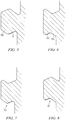
- Figures 5-8 of the drawings illustrate, in simplified fashion the regular arrow-shaped profile (55 in Figure 7 ), the reverse arrow-shaped profile (57 in Figure 8).
- Figures 5 and 6 illustrate additional thread forms which have the common feature of being comprised of only two facets on each flank, such as facets 59 and 61 in Figure 5 and facets 63 and 65 in Figure 6 .
- the differing designs illustrated in Figures 1 and 4 have different advantages, depending upon the end application.
- the regular arrow-shape profile illustrated in Figure 1 provides tensile load capabilities only afforded by a negative load flank angle thread form.
- the regular arrow-shape profile might be used most advantageously in oil field casing and tubing applications where the pipes are typically in tension.
- the reverse arrow-shape profile might be used more advantageously in such applications as horizontal or trenchless drilling where the pipe string is being "pushed" and is therefore in compression.
- one advantage of the thread form of the invention is the fact that it can be machined in either of two opposite directions, depending upon the anticipated applied load.
- the arrow-shape profile of the invention also has application for use in the so-called "expanded casing" applications which have come into fairly wide spread use in recent years.
- Expanded casing is used in some well construction operations where it is found to be advantageous to radially plastically expand threaded pipe or casing joints in a drilled open hole or inside a cased wellbore.
- radially expandable casing can be used to reinforce worn or damaged casing so as to, for example, increase a burst rating of the old casing, thereby preventing premature abandonment of the hole.
- the use of radially expandable casing may reduce a required diameter of a drilled hole for a desired final cased hole diameter, and may also reduce a required volume of cement required to fix the casing in wellbore.
- casing strings are installed at intervals whereby the casing for the next interval is installed through the casing for the previous interval.
- the outer diameter of a casing string is limited by the inner diameter of the previously installed casing string.
- the casing strings in a conventional wellbore are nested relative to each other, with casing diameters decreasing in a downward direction.
- An annular space is typically provided between each string of casing and the wellbore so that cement may be pumped into the annular space or annulus to seal between the casing and the wellbore.
- the hole diameter required at the top of the wellbore is relatively large. This large initial wellbore diameter may lead to increased costs due to the expense of large diameter casing, the expense of drilling large diameter holes, and the added expense of cementing a large casing string. Additionally, the nested arrangement of the casing strings in a conventional wellbore can severely limit the inner diameter of the final casing string at the bottom of the wellbore, which restricts the potential production rate of the well.
- Radially expanding a casing string in the wellbore has the added benefit of reducing the annular space between the drilled wellbore and the casing string, which reduces the amount of cement required to effect a seal between the casing and the wellbore.
- the radial expansion can be achieved by a cold-forming expansion process in which an expansion tool or "pig” is moved through a casing string so as to radially plastically expand the casing string.
- a cold-forming expansion process uses a conically tapered, cold-forming expansion tool to expand casing in a wellbore.
- the expansion tool is generally attached to a lower end of a casing string that is run into the wellbore.
- the expansion tool also includes a cylindrical section having a diameter typically corresponding to a desired expanded inner diameter of a casing string.
- the cylindrical section is followed by a tapered section. After the casing string is set in place in the hole, an axial upward lifting force is exerted on the working string to force the expansion tool upward through the casing string so as to outwardly radial displace the casing string to a desired expanded diameter.
- the threadforms utilized in expanded casing operations must be capable of securely joining the casing string and maintaining the integrity of the string so that the expansion operation does not significantly weaken the load carrying capacity of the threaded connection.
- axial strains in standard prior art connections can cause the connection to fail.
- the efficiency of the connection (commonly defined as the ratio of a mechanical property of the pipe body, such as axial tension capacity, to the same mechanical property across the connection) may drop severely after casing expansion.
- the pipe body wall thickness is also generally reduced during the expansion process, thus reducing the mechanical properties of the pipe body itself.
- the improved arrow-shaped thread profiles of the invention are well suited for use in expanded casing operations of the type described.
- assembly of a typical connection will be briefly discussed with respect to Figures 1 and 2 of the drawings.
- assembly of the pipe string normally involves a pipe joint being added to the existing string by lowering a section of pipe pin end down, into an upwardly facing box projecting from the drilling rig floor. After being stabbed into position, the added pipe joint is rotated to engage the threads of the pin and box, thereby securing the joint to the pipe string.
- the connections of the invention are generally free-running with the respective thread roots and crests, i.e., 13, 15 in Figure 2 , first making contact.
- the facet surfaces 21 and 25 make contact with their respective counterparts in the pin end.
- the facet surfaces 23 and 27 make contact with their respective counterpart surfaces in the box end of the connection.
- An invention has been provided with several advantages. Axial make-up of the threaded connection of the invention can be controlled by properly designing the specially profile interfit of the engagement surfaces of the threads themselves.
- the thread forms of the invention provide greater versatility in design than did the designs of the prior art. In some forms, the thread form works best in tension. In other forms, the thread form works best in compression.
- the thread form can be machined with a negative angle load flank, providing improved tensile loading capabilities.
- the thread form is extremely easy to machine, as compared to thread forms of this general type available in the marketplace.
- the thread form can be machined as a "wedge" thread to afford enhanced bending capabilities for the associated pipe string.
- the properties of the thread form of the invention make it ideally suited for expandable tubular applications.
- the geometry of the thread affords easy quality inspection using either mechanical or electronic methods.
- the thread form can be machined in either of two oppositely arranged directions, depending upon the anticipated loading of the pipe string.
Landscapes
- Engineering & Computer Science (AREA)
- Mechanical Engineering (AREA)
- Life Sciences & Earth Sciences (AREA)
- Geology (AREA)
- Mining & Mineral Resources (AREA)
- General Engineering & Computer Science (AREA)
- Physics & Mathematics (AREA)
- Environmental & Geological Engineering (AREA)
- Fluid Mechanics (AREA)
- General Life Sciences & Earth Sciences (AREA)
- Geochemistry & Mineralogy (AREA)
- Earth Drilling (AREA)
Claims (9)
- Gewindeform zur Herstellung einer Gewinderohrverbindung, die geeignet ist, verschraubt und nachfolgend getrennt zu werden, wobei die Form Folgendes umfasst:einen Bolzen (12) mit Außengewinde mit Aufsetzflanken (17) und Lastflanken (19) und flachen Spitzen (13) und Gründen (15), die zum passenden Innengewinde einer Muffe (11) passen, um eine Rohrverbindung herzustellen,dadurch gekennzeichnet, dass die Aufsetzflanken und die Lastflanken jedes Gewindeganges jeweils aus nur zwei Facetten (21, 23, 25, 27) bestehen und wobei sich sowohl die Facetten (25, 27) an den Aufsetzflanken als auch die entsprechenden Facetten (21, 23) an den Lastflanken jedes Gewindeganges in imaginären parallelen Ebenen (27, 29, 32, 33) in die gleiche Richtung neigen, so dass die Facetten bei Betrachtung im Profil eine Pfeilform bilden, undwobei das Vorhandensein von nur zwei Facetten an jeweils den Aufsetzflanken wie auch den Lastflanken und die Tatsache, dass sich die jeweils entsprechenden Facetten an sowohl den Aufsetz- als auch den Lastflanken in die gleiche Richtung neigen, es ermöglichen, die Gewindeform maschinell in einer von zwei entgegengesetzten Richtungen zu bearbeiten, was zu Gewindeformen führt, die exakte Spiegelbilder voneinander sind, wobei eine Spiegelbild-Gewindeform für Rohrverbindungen verwendbar ist, bei denen die Rohre unter Spannung stehen, und eine Spiegelbild-Gewindeform für Rohrverbindungen verwendbar ist, bei denen die Rohe unter Kompressionsdruck stehen.
- Gewindeform nach Anspruch 1, wobei die Gewindegänge mit einer negativ geneigten Facette gebildet sind, die an der Basis der Lastflanke einen Haken bildet.
- Gewindeform nach Anspruch 1, wobei die Gewindegänge eine gegebene Gewindehöhe aufweisen, die zwischen den Gewindespitzen und den Gewindegründen definiert ist, wobei die Gewindespitzen und die Gewindegründe eine gegebene Breite aufweisen und wobei die Breite an oder nahe den Gewindespitzen geringer als die Breite ist, die an den Gewindegründen gemessen wird.
- Gewindeform nach Anspruch 1, wobei das Gewinde ein sich verjüngendes Gewinde ist, das einen gegebenen Verjüngungswinkel im Verhältnis zur Längsachse des Rohres aufweist.
- Gewindeform nach Anspruch 1, wobei die Gewindegründe und -spitzen parallel zur Längsachse des Rohres liegen.
- Gewindeform nach Anspruch 1, wobei das Gewinde spiralförmig als ein Keil strukturiert ist.
- Gewindeform nach Anspruch 1, wobei die Verbindung mit einem Rohrsystem verwendet wird, das aus der Gruppe ausgewählt ist, die aus Öl-, Gas-, Konstruktions-, Wasser- und Abwasserverrohrung besteht.
- Gewinderohrverbindung zum Verbinden und Unterbrechen, die unter Verwendung einer Form nach Anspruch 1 hergestellt wird und geeignet ist, verschraubt und nachfolgend getrennt zu werden, wobei die Gewinderohrverbindung Folgendes umfasst:eine Muffe, die ein Innengewinde mit Aufsetzflanken und Lastflanken und flachen Gründen und Spitzen aufweist,einen passenden Bolzen, der ein Außengewinde mit Aufsetzflanken und Lastflanken und flachen Gründen und Spitzen aufweist und in das passende Innengewinde der Muffe passt, um eine Rohrverbindung herzustellen, und wobei die Aufsetzflanken und die Lastflanken jedes Gewindeganges des Bolzens aus nur zwei Facetten bestehen und wobei sich sowohl die Facetten an den Aufsetzflanken als auch die entsprechenden Facetten an den Lastflanken jedes Gewindeganges an dem Bolzen in imaginären parallelen Ebenen in die gleiche Richtung neigen, so dass die Facetten bei Betrachtung im Profil eine Pfeilform bilden, die zu einem entsprechenden Gewindeprofil am Gehäuse passt,wobei das Vorhandensein von nur zwei Facetten an jeweils den Aufsetzflanken wie auch den Lastflanken und die Tatsache, dass sich die jeweiligen entsprechenden Facetten an sowohl den Aufsetz- als auch den Lastflanken in die gleiche Richtung neigen, es ermöglichen, die Gewindeform maschinell in einer von zwei entgegengesetzten Richtungen zu bearbeiten, was zu Gewindeformen führt, die exakte Spiegelbilder voneinander sind, wobei eine Spiegelbild-Gewindeform für Rohrverbindungen verwendbar ist, bei denen die Rohre unter Spannung stehen, und eine Spiegelbild-Gewindeform für Rohrverbindungen verwendbar ist, bei denen die Rohe unter Kompressionsdruck stehen.
- Gewinderohrverbindung zum Verbinden und Unterbrechen nach Anspruch 8, wobei die Verbindung mit einem Rohrsystem verwendet wird, das aus der Gruppe ausgewählt ist, die aus einer Verrohrung für Öl- und Gasbohrlöcher, Wasser- und Abwasserschächte besteht.
Applications Claiming Priority (3)
| Application Number | Priority Date | Filing Date | Title |
|---|---|---|---|
| US22387409P | 2009-07-08 | 2009-07-08 | |
| US12/827,403 US8267436B2 (en) | 2009-07-08 | 2010-06-30 | Arrow-shaped thread form for tubular connections |
| PCT/US2010/040865 WO2011005669A1 (en) | 2009-07-08 | 2010-07-02 | Arrow-shaped thread form with tubular connections |
Publications (3)
| Publication Number | Publication Date |
|---|---|
| EP2452111A1 EP2452111A1 (de) | 2012-05-16 |
| EP2452111A4 EP2452111A4 (de) | 2016-05-25 |
| EP2452111B1 true EP2452111B1 (de) | 2017-08-30 |
Family
ID=43429493
Family Applications (1)
| Application Number | Title | Priority Date | Filing Date |
|---|---|---|---|
| EP10797659.9A Active EP2452111B1 (de) | 2009-07-08 | 2010-07-02 | Pfeilförmige gewindeform mit röhrenverbindungen |
Country Status (6)
| Country | Link |
|---|---|
| US (1) | US8267436B2 (de) |
| EP (1) | EP2452111B1 (de) |
| AU (1) | AU2010270806B2 (de) |
| CA (1) | CA2769936C (de) |
| NO (1) | NO2452111T3 (de) |
| WO (1) | WO2011005669A1 (de) |
Families Citing this family (12)
| Publication number | Priority date | Publication date | Assignee | Title |
|---|---|---|---|---|
| FR2953272B1 (fr) * | 2009-11-30 | 2011-12-16 | Vallourec Mannesmann Oil & Gas | Joint filete |
| GB2484064B (en) * | 2010-08-26 | 2016-01-06 | Rotite Ltd | Connector and method of connecting two items together |
| JP2015515596A (ja) * | 2012-04-27 | 2015-05-28 | アクソン イーピー,インコーポレイテッド | 可撓接続部 |
| US9670741B2 (en) * | 2013-12-16 | 2017-06-06 | Marubeni-Itochu Tubulars America, Inc. | Threaded connection |
| US10281066B2 (en) * | 2014-03-07 | 2019-05-07 | Houston International Specialty, Inc. | Flush threaded connection and method of forming and using the flush threaded connection |
| US10309198B2 (en) * | 2015-01-05 | 2019-06-04 | Morph Packers Limited | Pipe coupling |
| CN110476000B (zh) | 2017-03-31 | 2021-08-24 | 日本制铁株式会社 | 钢管用螺纹接头 |
| US11332982B2 (en) * | 2018-10-10 | 2022-05-17 | Coastal Pipe Usa, L.L.C. | Fatigue reducing shouldered connections |
| US11596459B2 (en) * | 2019-05-09 | 2023-03-07 | The University Of Hong Kong | Thread design for bone screw |
| EP4624017A3 (de) | 2019-10-30 | 2025-12-17 | Donaldson Company, Inc. | Filterpatrone |
| WO2022060638A1 (en) * | 2020-09-16 | 2022-03-24 | Van Cor Dale E | Key thread and key thread systems |
| WO2025054573A1 (en) * | 2023-09-08 | 2025-03-13 | Alsup Wesley | Variable angled loading threads |
Family Cites Families (8)
| Publication number | Priority date | Publication date | Assignee | Title |
|---|---|---|---|---|
| US4600224A (en) * | 1983-12-23 | 1986-07-15 | Interlock Technologies Corporation | Tubular connection having a chevron wedge thread |
| DE19531177A1 (de) * | 1995-08-24 | 1997-02-27 | Lorenz Gmbh | Anschluß für eine Armatur |
| US6254146B1 (en) * | 1999-04-23 | 2001-07-03 | John Gandy Corporation | Thread form with multifacited flanks |
| US6832789B2 (en) * | 2002-11-01 | 2004-12-21 | Torquelock Corporation | Threaded pipe connection with cylindrical metal-to-metal, high pressure containment seal |
| FR2863681B1 (fr) * | 2003-12-11 | 2006-02-24 | Vallourec Mannesmann Oil & Gas | Joint tubulaire a filetages coniques resistant a la fatigue |
| US7686350B2 (en) * | 2006-03-30 | 2010-03-30 | Hydril Llc | Mismatched flanks for a wedge thread |
| US7588269B2 (en) * | 2006-09-26 | 2009-09-15 | Gandy Technologies Corporation | Z-shaped thread form for tubular connections |
| US7690697B2 (en) * | 2007-05-09 | 2010-04-06 | Gandy Technologies Corp. | Thread form for tubular connections |
-
2010
- 2010-06-30 US US12/827,403 patent/US8267436B2/en active Active
- 2010-07-02 EP EP10797659.9A patent/EP2452111B1/de active Active
- 2010-07-02 WO PCT/US2010/040865 patent/WO2011005669A1/en not_active Ceased
- 2010-07-02 AU AU2010270806A patent/AU2010270806B2/en active Active
- 2010-07-02 CA CA2769936A patent/CA2769936C/en active Active
- 2010-07-02 NO NO10797659A patent/NO2452111T3/no unknown
Non-Patent Citations (1)
| Title |
|---|
| None * |
Also Published As
| Publication number | Publication date |
|---|---|
| CA2769936C (en) | 2017-09-12 |
| EP2452111A1 (de) | 2012-05-16 |
| US8267436B2 (en) | 2012-09-18 |
| AU2010270806A1 (en) | 2012-03-01 |
| WO2011005669A1 (en) | 2011-01-13 |
| EP2452111A4 (de) | 2016-05-25 |
| US20110012349A1 (en) | 2011-01-20 |
| AU2010270806B2 (en) | 2015-01-29 |
| NO2452111T3 (de) | 2018-01-27 |
| CA2769936A1 (en) | 2011-01-13 |
Similar Documents
| Publication | Publication Date | Title |
|---|---|---|
| US7690697B2 (en) | Thread form for tubular connections | |
| EP2452111B1 (de) | Pfeilförmige gewindeform mit röhrenverbindungen | |
| EP2347162B1 (de) | Zylinderförmiges kegelgewinde für röhrenverbindungen | |
| US9863560B2 (en) | Expansible threaded joint and method for making same | |
| US4373754A (en) | Threaded connector | |
| CA2780385C (en) | Threaded pipe connection with a pressure energized flex-seal | |
| WO2008039317A2 (en) | Z-shaped thread form for tubular connections | |
| US20060087119A1 (en) | Expandable threaded connection | |
| US8985640B2 (en) | Threaded pipe connection with a pressure energized flex-seal | |
| EP4073340B1 (de) | Gewindeverbindung, teilweise in einem selbstsichernden eingriff mit einer äusseren schulter, die einem erhöhten drehmoment standhalten kann | |
| CA3160975C (en) | Threaded connection partially in a self-locking engagement with an external shoulder capable to resist elevated torque |
Legal Events
| Date | Code | Title | Description |
|---|---|---|---|
| PUAI | Public reference made under article 153(3) epc to a published international application that has entered the european phase |
Free format text: ORIGINAL CODE: 0009012 |
|
| 17P | Request for examination filed |
Effective date: 20120131 |
|
| AK | Designated contracting states |
Kind code of ref document: A1 Designated state(s): AL AT BE BG CH CY CZ DE DK EE ES FI FR GB GR HR HU IE IS IT LI LT LU LV MC MK MT NL NO PL PT RO SE SI SK SM TR |
|
| DAX | Request for extension of the european patent (deleted) | ||
| RAP1 | Party data changed (applicant data changed or rights of an application transferred) |
Owner name: TORQUELOCK CORPORATION |
|
| RAP1 | Party data changed (applicant data changed or rights of an application transferred) |
Owner name: U.S. STEEL TUBULAR PRODUCTS, INC. |
|
| RA4 | Supplementary search report drawn up and despatched (corrected) |
Effective date: 20160421 |
|
| RIC1 | Information provided on ipc code assigned before grant |
Ipc: F16L 15/06 20060101AFI20160415BHEP Ipc: E21B 17/042 20060101ALI20160415BHEP |
|
| GRAP | Despatch of communication of intention to grant a patent |
Free format text: ORIGINAL CODE: EPIDOSNIGR1 |
|
| GRAJ | Information related to disapproval of communication of intention to grant by the applicant or resumption of examination proceedings by the epo deleted |
Free format text: ORIGINAL CODE: EPIDOSDIGR1 |
|
| INTG | Intention to grant announced |
Effective date: 20170215 |
|
| INTG | Intention to grant announced |
Effective date: 20170224 |
|
| GRAP | Despatch of communication of intention to grant a patent |
Free format text: ORIGINAL CODE: EPIDOSNIGR1 |
|
| INTG | Intention to grant announced |
Effective date: 20170302 |
|
| INTG | Intention to grant announced |
Effective date: 20170310 |
|
| INTG | Intention to grant announced |
Effective date: 20170324 |
|
| GRAS | Grant fee paid |
Free format text: ORIGINAL CODE: EPIDOSNIGR3 |
|
| GRAA | (expected) grant |
Free format text: ORIGINAL CODE: 0009210 |
|
| AK | Designated contracting states |
Kind code of ref document: B1 Designated state(s): AL AT BE BG CH CY CZ DE DK EE ES FI FR GB GR HR HU IE IS IT LI LT LU LV MC MK MT NL NO PL PT RO SE SI SK SM TR |
|
| REG | Reference to a national code |
Ref country code: GB Ref legal event code: FG4D |
|
| REG | Reference to a national code |
Ref country code: CH Ref legal event code: EP |
|
| REG | Reference to a national code |
Ref country code: AT Ref legal event code: REF Ref document number: 923890 Country of ref document: AT Kind code of ref document: T Effective date: 20170915 |
|
| REG | Reference to a national code |
Ref country code: IE Ref legal event code: FG4D |
|
| REG | Reference to a national code |
Ref country code: DE Ref legal event code: R096 Ref document number: 602010044876 Country of ref document: DE |
|
| REG | Reference to a national code |
Ref country code: RO Ref legal event code: EPE |
|
| REG | Reference to a national code |
Ref country code: NL Ref legal event code: MP Effective date: 20170830 |
|
| REG | Reference to a national code |
Ref country code: LT Ref legal event code: MG4D |
|
| PG25 | Lapsed in a contracting state [announced via postgrant information from national office to epo] |
Ref country code: SE Free format text: LAPSE BECAUSE OF FAILURE TO SUBMIT A TRANSLATION OF THE DESCRIPTION OR TO PAY THE FEE WITHIN THE PRESCRIBED TIME-LIMIT Effective date: 20170830 Ref country code: LT Free format text: LAPSE BECAUSE OF FAILURE TO SUBMIT A TRANSLATION OF THE DESCRIPTION OR TO PAY THE FEE WITHIN THE PRESCRIBED TIME-LIMIT Effective date: 20170830 Ref country code: HR Free format text: LAPSE BECAUSE OF FAILURE TO SUBMIT A TRANSLATION OF THE DESCRIPTION OR TO PAY THE FEE WITHIN THE PRESCRIBED TIME-LIMIT Effective date: 20170830 Ref country code: FI Free format text: LAPSE BECAUSE OF FAILURE TO SUBMIT A TRANSLATION OF THE DESCRIPTION OR TO PAY THE FEE WITHIN THE PRESCRIBED TIME-LIMIT Effective date: 20170830 |
|
| REG | Reference to a national code |
Ref country code: NO Ref legal event code: T2 Effective date: 20170830 |
|
| PG25 | Lapsed in a contracting state [announced via postgrant information from national office to epo] |
Ref country code: GR Free format text: LAPSE BECAUSE OF FAILURE TO SUBMIT A TRANSLATION OF THE DESCRIPTION OR TO PAY THE FEE WITHIN THE PRESCRIBED TIME-LIMIT Effective date: 20171201 Ref country code: ES Free format text: LAPSE BECAUSE OF FAILURE TO SUBMIT A TRANSLATION OF THE DESCRIPTION OR TO PAY THE FEE WITHIN THE PRESCRIBED TIME-LIMIT Effective date: 20170830 Ref country code: BG Free format text: LAPSE BECAUSE OF FAILURE TO SUBMIT A TRANSLATION OF THE DESCRIPTION OR TO PAY THE FEE WITHIN THE PRESCRIBED TIME-LIMIT Effective date: 20171130 Ref country code: IS Free format text: LAPSE BECAUSE OF FAILURE TO SUBMIT A TRANSLATION OF THE DESCRIPTION OR TO PAY THE FEE WITHIN THE PRESCRIBED TIME-LIMIT Effective date: 20171230 Ref country code: LV Free format text: LAPSE BECAUSE OF FAILURE TO SUBMIT A TRANSLATION OF THE DESCRIPTION OR TO PAY THE FEE WITHIN THE PRESCRIBED TIME-LIMIT Effective date: 20170830 |
|
| PG25 | Lapsed in a contracting state [announced via postgrant information from national office to epo] |
Ref country code: NL Free format text: LAPSE BECAUSE OF FAILURE TO SUBMIT A TRANSLATION OF THE DESCRIPTION OR TO PAY THE FEE WITHIN THE PRESCRIBED TIME-LIMIT Effective date: 20170830 |
|
| PG25 | Lapsed in a contracting state [announced via postgrant information from national office to epo] |
Ref country code: PL Free format text: LAPSE BECAUSE OF FAILURE TO SUBMIT A TRANSLATION OF THE DESCRIPTION OR TO PAY THE FEE WITHIN THE PRESCRIBED TIME-LIMIT Effective date: 20170830 Ref country code: CZ Free format text: LAPSE BECAUSE OF FAILURE TO SUBMIT A TRANSLATION OF THE DESCRIPTION OR TO PAY THE FEE WITHIN THE PRESCRIBED TIME-LIMIT Effective date: 20170830 Ref country code: DK Free format text: LAPSE BECAUSE OF FAILURE TO SUBMIT A TRANSLATION OF THE DESCRIPTION OR TO PAY THE FEE WITHIN THE PRESCRIBED TIME-LIMIT Effective date: 20170830 |
|
| PG25 | Lapsed in a contracting state [announced via postgrant information from national office to epo] |
Ref country code: SK Free format text: LAPSE BECAUSE OF FAILURE TO SUBMIT A TRANSLATION OF THE DESCRIPTION OR TO PAY THE FEE WITHIN THE PRESCRIBED TIME-LIMIT Effective date: 20170830 Ref country code: EE Free format text: LAPSE BECAUSE OF FAILURE TO SUBMIT A TRANSLATION OF THE DESCRIPTION OR TO PAY THE FEE WITHIN THE PRESCRIBED TIME-LIMIT Effective date: 20170830 Ref country code: SM Free format text: LAPSE BECAUSE OF FAILURE TO SUBMIT A TRANSLATION OF THE DESCRIPTION OR TO PAY THE FEE WITHIN THE PRESCRIBED TIME-LIMIT Effective date: 20170830 |
|
| REG | Reference to a national code |
Ref country code: DE Ref legal event code: R097 Ref document number: 602010044876 Country of ref document: DE |
|
| PLBE | No opposition filed within time limit |
Free format text: ORIGINAL CODE: 0009261 |
|
| STAA | Information on the status of an ep patent application or granted ep patent |
Free format text: STATUS: NO OPPOSITION FILED WITHIN TIME LIMIT |
|
| REG | Reference to a national code |
Ref country code: FR Ref legal event code: PLFP Year of fee payment: 9 |
|
| 26N | No opposition filed |
Effective date: 20180531 |
|
| PG25 | Lapsed in a contracting state [announced via postgrant information from national office to epo] |
Ref country code: SI Free format text: LAPSE BECAUSE OF FAILURE TO SUBMIT A TRANSLATION OF THE DESCRIPTION OR TO PAY THE FEE WITHIN THE PRESCRIBED TIME-LIMIT Effective date: 20170830 |
|
| REG | Reference to a national code |
Ref country code: CH Ref legal event code: PL |
|
| PG25 | Lapsed in a contracting state [announced via postgrant information from national office to epo] |
Ref country code: MC Free format text: LAPSE BECAUSE OF FAILURE TO SUBMIT A TRANSLATION OF THE DESCRIPTION OR TO PAY THE FEE WITHIN THE PRESCRIBED TIME-LIMIT Effective date: 20170830 Ref country code: LU Free format text: LAPSE BECAUSE OF NON-PAYMENT OF DUE FEES Effective date: 20180702 |
|
| REG | Reference to a national code |
Ref country code: BE Ref legal event code: MM Effective date: 20180731 |
|
| REG | Reference to a national code |
Ref country code: IE Ref legal event code: MM4A |
|
| PG25 | Lapsed in a contracting state [announced via postgrant information from national office to epo] |
Ref country code: LI Free format text: LAPSE BECAUSE OF NON-PAYMENT OF DUE FEES Effective date: 20180731 Ref country code: IE Free format text: LAPSE BECAUSE OF NON-PAYMENT OF DUE FEES Effective date: 20180702 Ref country code: CH Free format text: LAPSE BECAUSE OF NON-PAYMENT OF DUE FEES Effective date: 20180731 |
|
| PG25 | Lapsed in a contracting state [announced via postgrant information from national office to epo] |
Ref country code: BE Free format text: LAPSE BECAUSE OF NON-PAYMENT OF DUE FEES Effective date: 20180731 |
|
| PG25 | Lapsed in a contracting state [announced via postgrant information from national office to epo] |
Ref country code: MT Free format text: LAPSE BECAUSE OF NON-PAYMENT OF DUE FEES Effective date: 20180702 |
|
| PG25 | Lapsed in a contracting state [announced via postgrant information from national office to epo] |
Ref country code: TR Free format text: LAPSE BECAUSE OF FAILURE TO SUBMIT A TRANSLATION OF THE DESCRIPTION OR TO PAY THE FEE WITHIN THE PRESCRIBED TIME-LIMIT Effective date: 20170830 |
|
| PG25 | Lapsed in a contracting state [announced via postgrant information from national office to epo] |
Ref country code: PT Free format text: LAPSE BECAUSE OF FAILURE TO SUBMIT A TRANSLATION OF THE DESCRIPTION OR TO PAY THE FEE WITHIN THE PRESCRIBED TIME-LIMIT Effective date: 20170830 Ref country code: HU Free format text: LAPSE BECAUSE OF FAILURE TO SUBMIT A TRANSLATION OF THE DESCRIPTION OR TO PAY THE FEE WITHIN THE PRESCRIBED TIME-LIMIT; INVALID AB INITIO Effective date: 20100702 |
|
| PG25 | Lapsed in a contracting state [announced via postgrant information from national office to epo] |
Ref country code: MK Free format text: LAPSE BECAUSE OF NON-PAYMENT OF DUE FEES Effective date: 20170830 Ref country code: CY Free format text: LAPSE BECAUSE OF FAILURE TO SUBMIT A TRANSLATION OF THE DESCRIPTION OR TO PAY THE FEE WITHIN THE PRESCRIBED TIME-LIMIT Effective date: 20170830 |
|
| PG25 | Lapsed in a contracting state [announced via postgrant information from national office to epo] |
Ref country code: AL Free format text: LAPSE BECAUSE OF FAILURE TO SUBMIT A TRANSLATION OF THE DESCRIPTION OR TO PAY THE FEE WITHIN THE PRESCRIBED TIME-LIMIT Effective date: 20170830 |
|
| REG | Reference to a national code |
Ref country code: AT Ref legal event code: UEP Ref document number: 923890 Country of ref document: AT Kind code of ref document: T Effective date: 20170830 |
|
| REG | Reference to a national code |
Ref country code: NO Ref legal event code: CREP Representative=s name: PLOUGMANN VINGTOFT, C. J. HAMBROS PLASS 2, 0164 Ref country code: NO Ref legal event code: CHAD Owner name: U.S. STEEL TUBULAR PRODUCTS, US |
|
| REG | Reference to a national code |
Ref country code: DE Ref legal event code: R081 Ref document number: 602010044876 Country of ref document: DE Owner name: U.S. STEEL TUBULAR PRODUCTS, LLC, SPRING, US Free format text: FORMER OWNER: U.S. STEEL TUBULAR PRODUCTS, INC., PITTSBURGH, PA., US |
|
| REG | Reference to a national code |
Ref country code: AT Ref legal event code: HC Ref document number: 923890 Country of ref document: AT Kind code of ref document: T Owner name: U.S. STEEL TUBULAR PRODUCTS, LLC, US Effective date: 20250109 |
|
| PGFP | Annual fee paid to national office [announced via postgrant information from national office to epo] |
Ref country code: RO Payment date: 20250624 Year of fee payment: 16 |
|
| PGFP | Annual fee paid to national office [announced via postgrant information from national office to epo] |
Ref country code: DE Payment date: 20250722 Year of fee payment: 16 |
|
| PGFP | Annual fee paid to national office [announced via postgrant information from national office to epo] |
Ref country code: NO Payment date: 20250725 Year of fee payment: 16 |
|
| PGFP | Annual fee paid to national office [announced via postgrant information from national office to epo] |
Ref country code: IT Payment date: 20250724 Year of fee payment: 16 |
|
| PGFP | Annual fee paid to national office [announced via postgrant information from national office to epo] |
Ref country code: GB Payment date: 20250722 Year of fee payment: 16 |
|
| PGFP | Annual fee paid to national office [announced via postgrant information from national office to epo] |
Ref country code: FR Payment date: 20250725 Year of fee payment: 16 Ref country code: AT Payment date: 20250722 Year of fee payment: 16 |