EP1483149B1 - Controlled-deformation panel - Google Patents
Controlled-deformation panel Download PDFInfo
- Publication number
- EP1483149B1 EP1483149B1 EP03739642A EP03739642A EP1483149B1 EP 1483149 B1 EP1483149 B1 EP 1483149B1 EP 03739642 A EP03739642 A EP 03739642A EP 03739642 A EP03739642 A EP 03739642A EP 1483149 B1 EP1483149 B1 EP 1483149B1
- Authority
- EP
- European Patent Office
- Prior art keywords
- sheet
- tension wires
- wire
- tension
- shape
- Prior art date
- Legal status (The legal status is an assumption and is not a legal conclusion. Google has not performed a legal analysis and makes no representation as to the accuracy of the status listed.)
- Expired - Lifetime
Links
Images


Classifications
-
- B—PERFORMING OPERATIONS; TRANSPORTING
- B62—LAND VEHICLES FOR TRAVELLING OTHERWISE THAN ON RAILS
- B62D—MOTOR VEHICLES; TRAILERS
- B62D35/00—Vehicle bodies characterised by streamlining
- B62D35/007—Rear spoilers
-
- B—PERFORMING OPERATIONS; TRANSPORTING
- B62—LAND VEHICLES FOR TRAVELLING OTHERWISE THAN ON RAILS
- B62D—MOTOR VEHICLES; TRAILERS
- B62D35/00—Vehicle bodies characterised by streamlining
-
- B—PERFORMING OPERATIONS; TRANSPORTING
- B62—LAND VEHICLES FOR TRAVELLING OTHERWISE THAN ON RAILS
- B62D—MOTOR VEHICLES; TRAILERS
- B62D35/00—Vehicle bodies characterised by streamlining
- B62D35/005—Front spoilers
-
- B—PERFORMING OPERATIONS; TRANSPORTING
- B62—LAND VEHICLES FOR TRAVELLING OTHERWISE THAN ON RAILS
- B62D—MOTOR VEHICLES; TRAILERS
- B62D35/00—Vehicle bodies characterised by streamlining
- B62D35/02—Streamlining the undersurfaces
-
- B—PERFORMING OPERATIONS; TRANSPORTING
- B62—LAND VEHICLES FOR TRAVELLING OTHERWISE THAN ON RAILS
- B62D—MOTOR VEHICLES; TRAILERS
- B62D37/00—Stabilising vehicle bodies without controlling suspension arrangements
- B62D37/02—Stabilising vehicle bodies without controlling suspension arrangements by aerodynamic means
-
- F—MECHANICAL ENGINEERING; LIGHTING; HEATING; WEAPONS; BLASTING
- F03—MACHINES OR ENGINES FOR LIQUIDS; WIND, SPRING, OR WEIGHT MOTORS; PRODUCING MECHANICAL POWER OR A REACTIVE PROPULSIVE THRUST, NOT OTHERWISE PROVIDED FOR
- F03G—SPRING, WEIGHT, INERTIA OR LIKE MOTORS; MECHANICAL-POWER PRODUCING DEVICES OR MECHANISMS, NOT OTHERWISE PROVIDED FOR OR USING ENERGY SOURCES NOT OTHERWISE PROVIDED FOR
- F03G7/00—Mechanical-power-producing mechanisms, not otherwise provided for or using energy sources not otherwise provided for
- F03G7/06—Mechanical-power-producing mechanisms, not otherwise provided for or using energy sources not otherwise provided for using expansion or contraction of bodies due to heating, cooling, moistening, drying or the like
- F03G7/061—Mechanical-power-producing mechanisms, not otherwise provided for or using energy sources not otherwise provided for using expansion or contraction of bodies due to heating, cooling, moistening, drying or the like characterised by the actuating element
- F03G7/0614—Mechanical-power-producing mechanisms, not otherwise provided for or using energy sources not otherwise provided for using expansion or contraction of bodies due to heating, cooling, moistening, drying or the like characterised by the actuating element using shape memory elements
- F03G7/06143—Wires
-
- Y—GENERAL TAGGING OF NEW TECHNOLOGICAL DEVELOPMENTS; GENERAL TAGGING OF CROSS-SECTIONAL TECHNOLOGIES SPANNING OVER SEVERAL SECTIONS OF THE IPC; TECHNICAL SUBJECTS COVERED BY FORMER USPC CROSS-REFERENCE ART COLLECTIONS [XRACs] AND DIGESTS
- Y02—TECHNOLOGIES OR APPLICATIONS FOR MITIGATION OR ADAPTATION AGAINST CLIMATE CHANGE
- Y02T—CLIMATE CHANGE MITIGATION TECHNOLOGIES RELATED TO TRANSPORTATION
- Y02T10/00—Road transport of goods or passengers
- Y02T10/80—Technologies aiming to reduce greenhouse gasses emissions common to all road transportation technologies
- Y02T10/82—Elements for improving aerodynamics
-
- Y—GENERAL TAGGING OF NEW TECHNOLOGICAL DEVELOPMENTS; GENERAL TAGGING OF CROSS-SECTIONAL TECHNOLOGIES SPANNING OVER SEVERAL SECTIONS OF THE IPC; TECHNICAL SUBJECTS COVERED BY FORMER USPC CROSS-REFERENCE ART COLLECTIONS [XRACs] AND DIGESTS
- Y02—TECHNOLOGIES OR APPLICATIONS FOR MITIGATION OR ADAPTATION AGAINST CLIMATE CHANGE
- Y02T—CLIMATE CHANGE MITIGATION TECHNOLOGIES RELATED TO TRANSPORTATION
- Y02T10/00—Road transport of goods or passengers
- Y02T10/80—Technologies aiming to reduce greenhouse gasses emissions common to all road transportation technologies
- Y02T10/88—Optimized components or subsystems, e.g. lighting, actively controlled glasses
Definitions
- the present invention relates to a controlled-deformation panel.
- the present invention relates to a controlled-deformation panel which is particularly suitable for producing high-performance vehicle body parts, to which the following description refers purely by way of example.
- Movable spoilers obviously call for a number of electric and/or pneumatic actuators to move them between the rest or minimum-angle and the extracted or maximum-angle positions; and an electronic central control unit to coordinate operation of the electric and/or pneumatic actuators so as to adjust the aerodynamic configuration of the vehicle without producing a sharp change in the attitude, and so endangering the stability, of the vehicle.
- prototype high-performance vehicles have been designed in which the increase in vertical load depends, not on spoilers, but on a number of body plates capable, on command, of changing shape to alter the aerodynamic profile of the vehicle, i.e. the shape of the body, to increase the negative lift of the vehicle when necessary, i.e. generate a vertical load which presses the vehicle down onto the road.
- WO-9824690 discloses a controlled-deformation panel which comprises a sheet of elastically deformable material and a bundle of tension wires inserted at least partly inside the sheet, close to one of the two lateral surfaces of the sheet.
- the tension wires are anchored at their ends to the body of the sheet and the panel also comprises wire-tensioning means for selectively exerting mechanical pull on the tension wires to produce controlled deformation of the body of the sheet; this wire-tensioning means being made of shape-memory metal material.
- a car having a controlled-deformation panel according to the characterizing part of claim 1.
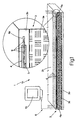
- number 1 indicates as a whole a controlled-deformation panel, which may be used to advantage for producing body parts of a vehicle 2, to alter, on command, the aerodynamic profile, i.e. the body shape, and so control negative lift of, the vehicle.
- controlled-deformation panel 1 may be used to advantage for producing the hood, luggage compartment lid, and/or the flat-underbody channels of a vehicle 2.
- panel 1 comprises a sheet 3 of elastically deformable material, e.g. a plastic material with or without reinforcing fibers; and a bundle of tension wires 4 inserted inside sheet 3, close to one of the two lateral surfaces of sheet 3.
- Tension wires 4 are anchored at both ends 4a to the body of sheet 3; and panel 1 also comprises wire-tensioning means for selectively exerting mechanical pull on tension wires 4 to produce controlled deformation of the body of sheet 3.
- the tensioning means of panel 1 reduce tension wires 4, on command, to a predetermined total length to produce controlled deformation of the body of sheet 3.
- sheet 3 is flat and rectangular, and comprises a central supporting core 3a of Nomex (i.e. a sheet of honeycomb aluminium of given thickness); and two cover sheets 3b of composite material (e.g. glass fiber or carbon fiber embedded in an epoxy resin matrix) covering central core 3a on opposite sides.
- Sheet 3 may obviously also be defined by a one-piece sheet of composite material of given thickness.
- tension wires 4 are housed and slide inside tubular sheaths 5 embedded in one of the two cover sheets 3b, are parallel to the two minor lateral edges of sheet 3, and are anchored to the body of sheet 3, at the major lateral edges of sheet 3, so that contraction, i.e. a reduction in the total length, of the wires causes the body of sheet 3 to curve into a semicylindrical shell.
- tension wires 4 are defined by wires made, along at least a portion of their length, of shape-memory metal material (e.g. a titanium-nickel, copper-zinc-aluminium, or copper-aluminium-nickel alloy), and able to assume a predetermined length L o at a temperature equal to or greater than a predetermined temperature T o .
- shape-memory metal material e.g. a titanium-nickel, copper-zinc-aluminium, or copper-aluminium-nickel alloy
- Shape-memory materials are metal materials capable of recovering a set macroscopic shape simply as a result of a change in temperature or applied stress, and of effecting a solid-state phase transformation in which the start and end phases are both solid structures differing only as regards the crystallographic arrangement.
- thermoplastic martensitic transformation Such a solid-state phase transformation is commonly known as “thermoplastic martensitic transformation", and the temperature at which it occurs as “transition temperature”.
- shape-memory materials are capable of assuming two different crystallographic configurations, depending on temperature: a first, commonly known as the martensitic phase, is typical of low temperatures and characterized by a high degree of deformability and a low yield point; a second, commonly known as the austenitic phase, is typical of high temperatures and characterized by a high degree of structural rigidity combined with a tendency to assume a predetermined macroscopic shape stored in the material itself by appropriate heat treatment.
- a first commonly known as the martensitic phase
- austenitic phase is typical of high temperatures and characterized by a high degree of structural rigidity combined with a tendency to assume a predetermined macroscopic shape stored in the material itself by appropriate heat treatment.
- each tension wire 4 is defined by a wire made entirely of shape-memory metal material appropriately heat treated to assume, in the austenitic phase, a macroscopic shape in which the total length of the wire equals length L o .
- tensions wires 4 When brought to a temperature equal to or greater than the "transition temperature", i.e. to a temperature equal to or greater than temperature T o , tensions wires 4 therefore all tend to assume the set length L o , thus deforming the body of sheet 3. More specifically, since length L o is less than the width d of sheet 3 at rest, when the temperature of tension wires 4 is equal to or greater than temperature T o , the body of sheet 3 tends to deform elastically and curve to bring the major lateral edges of sheet 3 closer together.
- the shape-memory metal material of which tension wires 4 are made has such a low yield point as to be less than the springback force which tends to restore sheet 3 to its original flat shape, so that tension wires 4 extend to a total length greater than length L o , and sheet 3 again assumes its natural, i.e. flat, shape.
- Tension wires 4 made at least partly of shape-memory metal material therefore also act as linear actuators capable, on command, of reducing the total length of tension wires 4 to length L o to produce controlled deformation of the body of sheet 3.
- panel 1 has a wire-heating device 8, which, on command, heats tension wires 4, or the portions of tension wires 4 made of shape-memory metal material, to a temperature equal to or greater than the "transition temperature", i.e. to temperature T o , so as to bring about the solid-state transformation phase typical of above cited shape-memory metal materials (i.e. "thermoplastic martensitic transformation").
- wire-heating device 8 comprises a number of electric resistors 9 arranged along tension wires 4; and an electronic central control unit 10, which, on command, feeds a given, not necessarily constant, electric current through the electric resistors to Joule-effect heat tension wires 4.
- Electric resistors 9 may be defined either by tension wires 4 themselves, which, being made of metal alloy, are electrically conductive, or by a number of wires made of electrically conductive material and coiled about tension wires 4.
- the wire-tensioning means comprise tension wires 4, or the portions of tension wires 4 made of shape-memory metal material; and wire-heating device 8.
- tension wires 4 are made entirely of steel, carbon fiber, or other high-strength material; and the wire-tensioning means comprise a number of linear actuators 11, each located along a respective tension wire 4 of panel 1, and for reducing, on command, the total length of respective tension wire 4 to length L o to produce controlled deformation of the body of sheet 3.
- each linear actuator 11 is located at one of the two ends 4a of respective tension wire 4, connects end 4a to the body of sheet 3 (the other end 4a of tension wire 4 is anchored to the body of sheet 3), and comprises: a hollow cartridge 12 anchored to the body of sheet 3 and coaxial with end 4a of tension wire 4; a piston 13 mounted to slide axially inside hollow cartridge 12; and two precompressed helical springs aligned with each other and housed inside hollow cartridge 12, on opposite sides of piston 13.
- the two precompressed helical springs hereinafter indicated 14 and 15, act on piston 13 in opposition to each other to keep piston 13 in a position of equilibrium depending on the coefficient of elasticity of helical springs 14 and 15.
- End 4a of tension wire 4 is fitted to slide through the shell of hollow cartridge 12, and is fixed to the body of piston 13; and one of helical springs 14, 15 - in the example shown, helical spring 14 - is made of shape-memory metal material appropriately heat treated so that the body of the spring has a predetermined axial length H o in the austenitic phase.
- helical spring 14 When brought to a temperature equal to or greater than the "transition temperature", i.e. to a temperature equal to or greater than temperature T o , helical spring 14 therefore tends to assume axial length H o , thus forcing piston 13 to assume, inside hollow cartridge 12, a new position of equilibrium in which the total length of the whole defined by tension wire 4 and relative linear actuator 11 equals the length L o required to produce predetermined controlled deformation of the body of sheet 3.
- the wire-tensioning means in the second embodiment of panel 1 also comprise a device for controlling the linear actuators 17, and which, on command, brings spring 14 to a temperature equal to or greater than the "transition temperature", i.e. to temperature T o , to bring about the solid-state phase transformation typical of shape-memory metal materials (i.e. "thermoplastic martensitic transformation").
- device controlling the linear actuators 17 comprises, in the example shown, a number of electric resistors 18 distributed along the body of helical spring 14; and an electronic central control unit 19, which, on command, feeds a given, not necessarily constant, electric current through electric resistors 18 to Joule-effect heat the body of spring 14.
- electric resistors 18 may be defined either by the body of helical spring 14, which, being made of metal alloy, is also electrically conductive, or by a number of wires made of electrically conductive material and coiled about the body of helical spring 14.
- controlled-deformation panel 1 Operation of controlled-deformation panel 1 is easily deducible from the foregoing description with no further explanation required.
- controlled-deformation panel 1 as described and illustrated herein are obvious: production cost is compatible with normal mass production, so that mass produced vehicles can also benefit from all the advantages, in terms of aerodynamic efficiency, derived from a vehicle body with no external spoilers, which increase drag, fuel consumption, and pollution.
- controlled-deformation panel 1 lies in it being extremely straightforward structurally, and therefore highly reliable.
- sheet 3 may be curved; in which case, tension wires 4 may be used to accentuate or reduce the curvature of sheet 3 on command.
- sheet 3 may comprise a number of reinforcing ribs projecting from one of the two faces of sheet 3, perpendicularly to the bundle of tension wires 4; and the tubular sheaths 5 housing tension wires 4 are fitted successively through all the reinforcing ribs, so that sheath portions embedded inside the reinforcing ribs alternate with sheath portions outside sheet 3.
Landscapes
- Engineering & Computer Science (AREA)
- Chemical & Material Sciences (AREA)
- Combustion & Propulsion (AREA)
- Mechanical Engineering (AREA)
- Transportation (AREA)
- General Engineering & Computer Science (AREA)
- Physics & Mathematics (AREA)
- Fluid Mechanics (AREA)
- Body Structure For Vehicles (AREA)
- Panels For Use In Building Construction (AREA)
- Springs (AREA)
Applications Claiming Priority (3)
| Application Number | Priority Date | Filing Date | Title |
|---|---|---|---|
| ITTO20020134 | 2002-02-15 | ||
| IT2002TO000134A ITTO20020134A1 (it) | 2002-02-15 | 2002-02-15 | Pannello a deformazione comandata. |
| PCT/IT2003/000078 WO2003068584A1 (en) | 2002-02-15 | 2003-02-14 | Controlled-deformation panel |
Publications (2)
| Publication Number | Publication Date |
|---|---|
| EP1483149A1 EP1483149A1 (en) | 2004-12-08 |
| EP1483149B1 true EP1483149B1 (en) | 2007-08-22 |
Family
ID=27638846
Family Applications (1)
| Application Number | Title | Priority Date | Filing Date |
|---|---|---|---|
| EP03739642A Expired - Lifetime EP1483149B1 (en) | 2002-02-15 | 2003-02-14 | Controlled-deformation panel |
Country Status (5)
| Country | Link |
|---|---|
| EP (1) | EP1483149B1 (it) |
| AU (1) | AU2003215895A1 (it) |
| DE (1) | DE60315807T2 (it) |
| IT (1) | ITTO20020134A1 (it) |
| WO (1) | WO2003068584A1 (it) |
Families Citing this family (14)
| Publication number | Priority date | Publication date | Assignee | Title |
|---|---|---|---|---|
| ITTO20030989A1 (it) * | 2003-12-10 | 2005-06-11 | Fiat Ricerche | Dispositivo a barriera aerodinamica a scomparsa predisponibile sotto il pianale di un autoveicolo, ed autoveicolo di tale dispositivo. |
| FR2879158B1 (fr) * | 2004-12-13 | 2008-07-04 | Plastic Omnium Cie | Capot avant a conducteurs electriques pour vehicule automobile |
| US7777165B2 (en) | 2007-02-02 | 2010-08-17 | Raytheon Company | Methods and apparatus for adjustable surfaces |
| US8382042B2 (en) | 2008-05-14 | 2013-02-26 | Raytheon Company | Structure with reconfigurable polymer material |
| US8016249B2 (en) | 2008-05-14 | 2011-09-13 | Raytheon Company | Shape-changing structure member with embedded spring |
| US7939178B2 (en) | 2008-05-14 | 2011-05-10 | Raytheon Company | Shape-changing structure with superelastic foam material |
| US8262032B2 (en) | 2008-11-13 | 2012-09-11 | Raytheon Company | Collapsible wing beams and method |
| US8056853B2 (en) | 2008-11-25 | 2011-11-15 | Raytheon Company | Reconfigurable wing and method of use |
| US8387536B2 (en) | 2008-12-04 | 2013-03-05 | Raytheon Company | Interceptor vehicle with extendible arms |
| US8573535B2 (en) | 2009-03-27 | 2013-11-05 | Raytheon Company | Shape-change material and method |
| WO2013066439A1 (en) | 2011-11-04 | 2013-05-10 | Raytheon Company | Chord-expanding air vehicle wings |
| JP5971773B2 (ja) * | 2014-04-06 | 2016-08-17 | トヨタ自動車株式会社 | 面形状可変装置 |
| DE102019206782A1 (de) * | 2019-05-10 | 2020-09-17 | Audi Ag | Interaktionsvorrichtung für ein Fahrzeug |
| US20260015046A1 (en) * | 2024-07-15 | 2026-01-15 | Ferrari S.P.A. | Vehicle with a morphing bodywork |
Family Cites Families (4)
| Publication number | Priority date | Publication date | Assignee | Title |
|---|---|---|---|---|
| US5150864A (en) * | 1991-09-20 | 1992-09-29 | Georgia Tech Research Corporation | Variable camber control of airfoil |
| CA2219057A1 (en) * | 1996-12-06 | 1998-06-06 | Francois Trochu | Three-dimensional active, composite membrane, typically sma actuated |
| US6124662A (en) * | 1999-03-22 | 2000-09-26 | Maness; Richard | Actuator using electrical contacts pressed in abutment |
| DE10026264A1 (de) * | 2000-05-26 | 2001-11-29 | Bayerische Motoren Werke Ag | Kraftfahrzeug-Außenhaut |
-
2002
- 2002-02-15 IT IT2002TO000134A patent/ITTO20020134A1/it unknown
-
2003
- 2003-02-14 AU AU2003215895A patent/AU2003215895A1/en not_active Abandoned
- 2003-02-14 DE DE60315807T patent/DE60315807T2/de not_active Expired - Lifetime
- 2003-02-14 EP EP03739642A patent/EP1483149B1/en not_active Expired - Lifetime
- 2003-02-14 WO PCT/IT2003/000078 patent/WO2003068584A1/en not_active Ceased
Also Published As
| Publication number | Publication date |
|---|---|
| AU2003215895A1 (en) | 2003-09-04 |
| DE60315807T2 (de) | 2008-05-21 |
| ITTO20020134A0 (it) | 2002-02-15 |
| WO2003068584A1 (en) | 2003-08-21 |
| EP1483149A1 (en) | 2004-12-08 |
| DE60315807D1 (de) | 2007-10-04 |
| ITTO20020134A1 (it) | 2003-08-18 |
| WO2003068584A8 (en) | 2004-04-08 |
Similar Documents
| Publication | Publication Date | Title |
|---|---|---|
| EP1483149B1 (en) | Controlled-deformation panel | |
| EP1485289B1 (en) | Apparatus and method for variation of a wall skin | |
| US20090314404A1 (en) | Methods of reducing tire rolling resistance utilizing active material actuation | |
| US6991280B2 (en) | Airflow control devices based on active materials | |
| US7931240B2 (en) | Cellular support structures used for controlled actuation of fluid contact surfaces | |
| US6182929B1 (en) | Load carrying structure having variable flexibility | |
| US10543897B2 (en) | Systems for shape memory alloy structures | |
| US6234528B1 (en) | Impact energy absorption modulating means | |
| JP4832373B2 (ja) | 形状記憶合金アクチュエータ | |
| EP2570640B1 (en) | A variable geometry structure | |
| US10703425B2 (en) | Air-guiding device | |
| WO2005060476A2 (en) | Airflow control devices based on active materials | |
| US20120114778A1 (en) | Surface texturing using foldable structures and active material actuation | |
| CN104708622B (zh) | 一种往复运动机构 | |
| US9096012B2 (en) | Surface texturing using engineered structures | |
| CN109973342A (zh) | 形状记忆驱动式软体驱动器及其控制方法、制作方法 | |
| KR101007764B1 (ko) | 자동차의 섀시용 롤 스태빌라이저 | |
| KR101333252B1 (ko) | 가변형 모핑 날개 | |
| JP4889844B2 (ja) | 連続エネルギー吸収システム | |
| CN114104262B (zh) | 一种可变形的机翼组件 | |
| CN117227964B (zh) | 多连杆可变结构机翼及航行器 | |
| US20250121660A1 (en) | Assembly for moving a cover | |
| CN114204840B (zh) | 基于可调预压缩力压电双晶片的舵面偏转机构及其方法 | |
| EP4682031A1 (en) | Vehicle with a morphing bodywork | |
| Yang et al. | A compact and flexible actuator based on shape memory alloy springs |
Legal Events
| Date | Code | Title | Description |
|---|---|---|---|
| PUAI | Public reference made under article 153(3) epc to a published international application that has entered the european phase |
Free format text: ORIGINAL CODE: 0009012 |
|
| 17P | Request for examination filed |
Effective date: 20040914 |
|
| AK | Designated contracting states |
Kind code of ref document: A1 Designated state(s): AT BE BG CH CY CZ DE DK EE ES FI FR GB GR HU IE IT LI LU MC NL PT SE SI SK TR |
|
| AX | Request for extension of the european patent |
Extension state: AL LT LV MK RO |
|
| 17Q | First examination report despatched |
Effective date: 20050304 |
|
| GRAP | Despatch of communication of intention to grant a patent |
Free format text: ORIGINAL CODE: EPIDOSNIGR1 |
|
| GRAS | Grant fee paid |
Free format text: ORIGINAL CODE: EPIDOSNIGR3 |
|
| GRAA | (expected) grant |
Free format text: ORIGINAL CODE: 0009210 |
|
| AK | Designated contracting states |
Kind code of ref document: B1 Designated state(s): DE ES FR GB SE |
|
| REG | Reference to a national code |
Ref country code: GB Ref legal event code: FG4D |
|
| REF | Corresponds to: |
Ref document number: 60315807 Country of ref document: DE Date of ref document: 20071004 Kind code of ref document: P |
|
| PG25 | Lapsed in a contracting state [announced via postgrant information from national office to epo] |
Ref country code: ES Free format text: LAPSE BECAUSE OF FAILURE TO SUBMIT A TRANSLATION OF THE DESCRIPTION OR TO PAY THE FEE WITHIN THE PRESCRIBED TIME-LIMIT Effective date: 20071203 |
|
| EN | Fr: translation not filed | ||
| PLBE | No opposition filed within time limit |
Free format text: ORIGINAL CODE: 0009261 |
|
| STAA | Information on the status of an ep patent application or granted ep patent |
Free format text: STATUS: NO OPPOSITION FILED WITHIN TIME LIMIT |
|
| PG25 | Lapsed in a contracting state [announced via postgrant information from national office to epo] |
Ref country code: SE Free format text: LAPSE BECAUSE OF FAILURE TO SUBMIT A TRANSLATION OF THE DESCRIPTION OR TO PAY THE FEE WITHIN THE PRESCRIBED TIME-LIMIT Effective date: 20071122 |
|
| 26N | No opposition filed |
Effective date: 20080526 |
|
| PG25 | Lapsed in a contracting state [announced via postgrant information from national office to epo] |
Ref country code: FR Free format text: LAPSE BECAUSE OF FAILURE TO SUBMIT A TRANSLATION OF THE DESCRIPTION OR TO PAY THE FEE WITHIN THE PRESCRIBED TIME-LIMIT Effective date: 20080418 |
|
| PGFP | Annual fee paid to national office [announced via postgrant information from national office to epo] |
Ref country code: GB Payment date: 20220222 Year of fee payment: 20 Ref country code: DE Payment date: 20220225 Year of fee payment: 20 |
|
| REG | Reference to a national code |
Ref country code: DE Ref legal event code: R071 Ref document number: 60315807 Country of ref document: DE |
|
| REG | Reference to a national code |
Ref country code: GB Ref legal event code: PE20 Expiry date: 20230213 |
|
| PG25 | Lapsed in a contracting state [announced via postgrant information from national office to epo] |
Ref country code: GB Free format text: LAPSE BECAUSE OF EXPIRATION OF PROTECTION Effective date: 20230213 |