EP1483089B1 - Vorrichtung zum schneiden von holz ohne sägespäne - Google Patents
Vorrichtung zum schneiden von holz ohne sägespäne Download PDFInfo
- Publication number
- EP1483089B1 EP1483089B1 EP03706148A EP03706148A EP1483089B1 EP 1483089 B1 EP1483089 B1 EP 1483089B1 EP 03706148 A EP03706148 A EP 03706148A EP 03706148 A EP03706148 A EP 03706148A EP 1483089 B1 EP1483089 B1 EP 1483089B1
- Authority
- EP
- European Patent Office
- Prior art keywords
- wood
- sawdust
- cutting apparatus
- piece
- roller
- Prior art date
- Legal status (The legal status is an assumption and is not a legal conclusion. Google has not performed a legal analysis and makes no representation as to the accuracy of the status listed.)
- Expired - Lifetime
Links
- 239000002023 wood Substances 0.000 title claims abstract description 81
- 238000011144 upstream manufacturing Methods 0.000 claims description 4
- 238000005096 rolling process Methods 0.000 claims description 2
- 230000005540 biological transmission Effects 0.000 claims 1
- 229910000746 Structural steel Inorganic materials 0.000 description 4
- 239000000463 material Substances 0.000 description 4
- 239000002699 waste material Substances 0.000 description 3
- 241000218657 Picea Species 0.000 description 2
- 229920002522 Wood fibre Polymers 0.000 description 2
- 230000002093 peripheral effect Effects 0.000 description 2
- 239000002025 wood fiber Substances 0.000 description 2
- 239000000428 dust Substances 0.000 description 1
- 238000009434 installation Methods 0.000 description 1
- 230000035515 penetration Effects 0.000 description 1
- 239000011505 plaster Substances 0.000 description 1
- 239000002916 wood waste Substances 0.000 description 1
Images


Classifications
-
- B—PERFORMING OPERATIONS; TRANSPORTING
- B27—WORKING OR PRESERVING WOOD OR SIMILAR MATERIAL; NAILING OR STAPLING MACHINES IN GENERAL
- B27M—WORKING OF WOOD NOT PROVIDED FOR IN SUBCLASSES B27B - B27L; MANUFACTURE OF SPECIFIC WOODEN ARTICLES
- B27M1/00—Working of wood not provided for in subclasses B27B - B27L, e.g. by stretching
-
- B—PERFORMING OPERATIONS; TRANSPORTING
- B26—HAND CUTTING TOOLS; CUTTING; SEVERING
- B26D—CUTTING; DETAILS COMMON TO MACHINES FOR PERFORATING, PUNCHING, CUTTING-OUT, STAMPING-OUT OR SEVERING
- B26D5/00—Arrangements for operating and controlling machines or devices for cutting, cutting-out, stamping-out, punching, perforating, or severing by means other than cutting
- B26D5/20—Arrangements for operating and controlling machines or devices for cutting, cutting-out, stamping-out, punching, perforating, or severing by means other than cutting with interrelated action between the cutting member and work feed
- B26D5/22—Arrangements for operating and controlling machines or devices for cutting, cutting-out, stamping-out, punching, perforating, or severing by means other than cutting with interrelated action between the cutting member and work feed having the cutting member and work feed mechanically connected
-
- Y—GENERAL TAGGING OF NEW TECHNOLOGICAL DEVELOPMENTS; GENERAL TAGGING OF CROSS-SECTIONAL TECHNOLOGIES SPANNING OVER SEVERAL SECTIONS OF THE IPC; TECHNICAL SUBJECTS COVERED BY FORMER USPC CROSS-REFERENCE ART COLLECTIONS [XRACs] AND DIGESTS
- Y10—TECHNICAL SUBJECTS COVERED BY FORMER USPC
- Y10T—TECHNICAL SUBJECTS COVERED BY FORMER US CLASSIFICATION
- Y10T83/00—Cutting
- Y10T83/02—Other than completely through work thickness
- Y10T83/0267—Splitting
- Y10T83/0281—By use of rotary blade
- Y10T83/0289—Plural independent rotary blades
-
- Y—GENERAL TAGGING OF NEW TECHNOLOGICAL DEVELOPMENTS; GENERAL TAGGING OF CROSS-SECTIONAL TECHNOLOGIES SPANNING OVER SEVERAL SECTIONS OF THE IPC; TECHNICAL SUBJECTS COVERED BY FORMER USPC CROSS-REFERENCE ART COLLECTIONS [XRACs] AND DIGESTS
- Y10—TECHNICAL SUBJECTS COVERED BY FORMER USPC
- Y10T—TECHNICAL SUBJECTS COVERED BY FORMER US CLASSIFICATION
- Y10T83/00—Cutting
- Y10T83/02—Other than completely through work thickness
- Y10T83/0333—Scoring
- Y10T83/0363—Plural independent scoring blades
- Y10T83/037—Rotary scoring blades
- Y10T83/0378—On opposite sides of work
-
- Y—GENERAL TAGGING OF NEW TECHNOLOGICAL DEVELOPMENTS; GENERAL TAGGING OF CROSS-SECTIONAL TECHNOLOGIES SPANNING OVER SEVERAL SECTIONS OF THE IPC; TECHNICAL SUBJECTS COVERED BY FORMER USPC CROSS-REFERENCE ART COLLECTIONS [XRACs] AND DIGESTS
- Y10—TECHNICAL SUBJECTS COVERED BY FORMER USPC
- Y10T—TECHNICAL SUBJECTS COVERED BY FORMER US CLASSIFICATION
- Y10T83/00—Cutting
- Y10T83/04—Processes
- Y10T83/0581—Cutting part way through from opposite sides of work
-
- Y—GENERAL TAGGING OF NEW TECHNOLOGICAL DEVELOPMENTS; GENERAL TAGGING OF CROSS-SECTIONAL TECHNOLOGIES SPANNING OVER SEVERAL SECTIONS OF THE IPC; TECHNICAL SUBJECTS COVERED BY FORMER USPC CROSS-REFERENCE ART COLLECTIONS [XRACs] AND DIGESTS
- Y10—TECHNICAL SUBJECTS COVERED BY FORMER USPC
- Y10T—TECHNICAL SUBJECTS COVERED BY FORMER US CLASSIFICATION
- Y10T83/00—Cutting
- Y10T83/465—Cutting motion of tool has component in direction of moving work
-
- Y—GENERAL TAGGING OF NEW TECHNOLOGICAL DEVELOPMENTS; GENERAL TAGGING OF CROSS-SECTIONAL TECHNOLOGIES SPANNING OVER SEVERAL SECTIONS OF THE IPC; TECHNICAL SUBJECTS COVERED BY FORMER USPC CROSS-REFERENCE ART COLLECTIONS [XRACs] AND DIGESTS
- Y10—TECHNICAL SUBJECTS COVERED BY FORMER USPC
- Y10T—TECHNICAL SUBJECTS COVERED BY FORMER US CLASSIFICATION
- Y10T83/00—Cutting
- Y10T83/647—With means to convey work relative to tool station
- Y10T83/6584—Cut made parallel to direction of and during work movement
-
- Y—GENERAL TAGGING OF NEW TECHNOLOGICAL DEVELOPMENTS; GENERAL TAGGING OF CROSS-SECTIONAL TECHNOLOGIES SPANNING OVER SEVERAL SECTIONS OF THE IPC; TECHNICAL SUBJECTS COVERED BY FORMER USPC CROSS-REFERENCE ART COLLECTIONS [XRACs] AND DIGESTS
- Y10—TECHNICAL SUBJECTS COVERED BY FORMER USPC
- Y10T—TECHNICAL SUBJECTS COVERED BY FORMER US CLASSIFICATION
- Y10T83/00—Cutting
- Y10T83/727—With means to guide moving work
- Y10T83/741—With movable or yieldable guide element
- Y10T83/743—Opposed to work-supporting surface
-
- Y—GENERAL TAGGING OF NEW TECHNOLOGICAL DEVELOPMENTS; GENERAL TAGGING OF CROSS-SECTIONAL TECHNOLOGIES SPANNING OVER SEVERAL SECTIONS OF THE IPC; TECHNICAL SUBJECTS COVERED BY FORMER USPC CROSS-REFERENCE ART COLLECTIONS [XRACs] AND DIGESTS
- Y10—TECHNICAL SUBJECTS COVERED BY FORMER USPC
- Y10T—TECHNICAL SUBJECTS COVERED BY FORMER US CLASSIFICATION
- Y10T83/00—Cutting
- Y10T83/748—With work immobilizer
- Y10T83/7487—Means to clamp work
-
- Y—GENERAL TAGGING OF NEW TECHNOLOGICAL DEVELOPMENTS; GENERAL TAGGING OF CROSS-SECTIONAL TECHNOLOGIES SPANNING OVER SEVERAL SECTIONS OF THE IPC; TECHNICAL SUBJECTS COVERED BY FORMER USPC CROSS-REFERENCE ART COLLECTIONS [XRACs] AND DIGESTS
- Y10—TECHNICAL SUBJECTS COVERED BY FORMER USPC
- Y10T—TECHNICAL SUBJECTS COVERED BY FORMER US CLASSIFICATION
- Y10T83/00—Cutting
- Y10T83/929—Tool or tool with support
- Y10T83/9372—Rotatable type
- Y10T83/9403—Disc type
Definitions
- the present invention relates generally to wood industries and, more particularly, to a sawdust-free cutting apparatus according to the preamble of claim 1.
- wood pieces are typically sawn by bringing the wood pieces in contact with a rotating circular saw having a toothed outer circumference.
- a rotating circular saw having a toothed outer circumference.
- sawdust which constitutes an important source of waste.
- United States Patent No. 4,009,741 issued on March 1, 1997 to Zimmerman discloses a woodworking machine comprising a number of power driven feed rollers for feeding wood products into and through a cutting zone.
- the cutting zone includes a pair of coplanar toothed saw blades.
- An overhead dust collector is provided above the cutting zone to carry away virtually all sawdust generated while the machine is being operated.
- FR 1 277 394 A describes a sawdust-free wood cutting apparatus comprising:
- a sawdust-free wood cutting apparatus embodying the elements of the present invention and generally designated by the numeral 10 will be described.
- the elements of the present invention and generally designated by the numeral 10 will be described.
- by cutting with at least one blade, as opposed to sawing it is possible to use virtually 100% of the volume of wood to be processed. That is to say that very little waste or no waste at all occurs in the wood cutting apparatus 10.
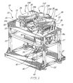
- the sawdust-free wood cutting apparatus 10 is intended to cut wood pieces, such as a wooden board, wood planks and lumbers. More specifically, the sawdust-free wood cutting apparatus 10 generally comprises a table 12, a pair of vertically spaced-apart feed rollers 14a and 14b at an upstream end 15 of the table 12, a pair of discharge rollers 16a and 16b at a downstream end 17 of the table 12, and a pair of coplanar circular cutting blades 18a and 18b between the pairs of feed and discharge rollers 14a, 14b, 16a and 16b.
- the table 12 includes a horizontal planar support surface 20 supported above a ground surface by four legs 22 depending from the corners of the support surface 20.
- First and second axially spaced-apart rectangular slots are defined in the support surface 20 for respectively receiving the feed roller 14a and the discharge roller 16a with the peripheral side surface of the rollers 14a and 16a substantially flush with the top surface of the support surface 20.
- the feed roller 14a and the discharge roller 16a are identical and journaled to the table 12 for free rotation about respective rotating axes.
- the rollers 14a and 16a are not power driven and are caused to be rotated only by the piece of wood W (Figs. 7 and 8) traveling thereon from the upstream end 15 of the table 12 to the downstream end 17 thereof.
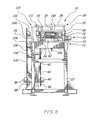
- each mounting structure 28 includes a roller mounting plate 30 provided with downwardly depending cylindrical bushings 32 at the corners thereof for sliding movement along four vertical cylindrical rods 33 extending upwardly from the support surface 20.
- Each roller mounting plate 30 carries a pair of laterally spaced-apart pillow blocks 34 (Fig. 8) on an undersurface thereof for rotatably supporting one of the feed roller 14b and discharge roller 16b.
- a top plate 36 is secured to the upper distal end of the rods 33.
- An adjustable biasing structure 38 such as a spring or a piston and cylinder arrangement, is provided between the top plate 36 and the underlying roller mounting plate 30 to provide adjustability for vertical translating and positioning of the rollers 14b and 16b against the top surface of the piece of wood W to be processed.
- the upper feed and discharge rollers 14b and 16b are preferably ribbed and made of a material having a high coefficient of friction to prevent any slippage between the piece of wood W and the rollers 14b and 16b while the piece of wood W is being advanced by the rollers 14b and 16b through the apparatus 10.
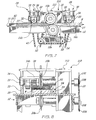
- the feed roller 14b and the discharge roller 16b are both power driven by a motor 40 via an endless drive chain 42 engaged on a sprocket wheel 44 mounted on a first output shaft 46 of a gear box 48 operatively connected to the motor 40.
- the drive chain 42 extends over a sprocket wheel 50 (Fig. 6) connected to the feed roller 14b and then over two intermediate sprockets 52 and 54 mounted to the table 12.
- the drive chain 42 extends from the sprocket 54 to another sprocket 56 (Fig. 4) connected to the discharge roller 16b.
- the chain 42 then engages a second pair of intermediate sprockets 58 and 60, which are mounted to the table 12, before returning to the sprocket 44.
- the sprockets 50 and 56 are identical to ensure that the tangential speed at the periphery of the rollers 14b and 16b is equal. This speed corresponds to the advancing speed of the wood piece W through the apparatus 10.
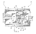
- the piece of wood W is guided along a rectilinear feed path through the apparatus 10 in order to ensure straight cuts C (Fig. 3). As best shown in Fig. 3, this is achieved by urging one lateral edge of the piece of wood W in sliding contact with a vertical guiding surface 62 of an axially extending angle iron 64 or the like adjustably mounted on one side of the feed path.
- the angle iron 64 has a horizontal foot 68 in which a given number of slots 66 are defined for receiving fasteners.
- a plurality of fastener receiving holes 70 are defined in the support surface 20 of the table 12 for allowing the angle iron 64 to be secured in a variety of lateral positions on the support surface 20.
- the pushing mechanism 72 includes a base plate 74 defining a pair of slots 76 (Fig. 3) adapted to receive fasteners 78 (Fig.3) for adjustably mounting the base plate 74 on the support surface 20 of the table 12.
- a pivot plate 80 having a boomerang-like shape is pivotally mounted at 82 to the base plate 74 for pivotal movement about a vertical axis.
- the pivot plate 80 carries at an apex thereof a roller 84 having a vertical pivot axis 86.
- a pneumatic cylinder 88 or the like is pivotally mounted at 90 to a bracket 92 fixed to the base plate 74.
- the pneumatic cylinder 88 has a piston 94 having a distal end pivotally connected to one end of the pivot plate 80 opposite the pivot 82.
- the pneumatic cylinder 88 is adjusted to bias the roller 84 in rolling contact with one side of the piece of wood W and, thus, maintain the other side of the piece of wood W in sliding contact the guiding surface 62.
- the piece of wood W is cut longitudinally into two parts by the combined action of the axially spaced coplanar circular cutting blades 18a and 18b.
- the lower and upper coplanar blades 18a and 18b are placed slantwise behind each other so that their combined penetration depth equals at least the thickness of the piece of wood W to ensure a complete cut therethrough.
- the blades 18a and 18b are provided in the form of smooth edged circular blades. According to the illustrated embodiment, both blades have the same diameter and a same sharpened circumferential edge. As shown in Fig.8, each blade 18a/18b tapers on each blade side around its sharpened circumferential edge regions.
- the circular blades 18a and 18b are fixedly mounted to respective shafts 106 and 108 journaled to a box-like structure 110 mounted on the table 12.
- the upper circular blade 18b is vertically adjustable by a screw adjustment mechanism generally depicted at 112.
- the blades 18a and 18b are driven at the same speed but in opposite directions by the motor 40.
- the gear box 48 is provided with a second output shaft 96 having a sprocket wheel 98 mounted thereon.
- An endless drive chain 100 extends over the sprocket wheel 98 for transmitting power to two other sprocket wheels 102 and 104 respectively mounted to the shafts 108 and 106 of the upper and lower circular cutting blades 18b and 18a.
- a tensor equipped with a sprocket wheel 114 is engaged with the drive chain 100 to maintain an appropriate tension therein.
- the blades 18a and 18b are driven at the same speed but in opposite directions (see Fig. 7) so that the tangential speed at the outer circumference thereof be equal to the advancing speed of the piece of wood W advanced from the upstream end 15 of the table 12 to the downstream end thereof 17 by the feed and discharge rollers 14b and 16b.
- the piece of wood W is cut, as opposed to being sawn, and virtually no sawdust is generated.
- the friction between the blades 18a and 18b and the piece of wood W is almost reduced to zero.
- the above-described driving arrangement of sprocket wheels and chains driving the feed roller 14b, the discharge roller 16b and the blades 18a and 18b guarantee the equality of the advancing speed of the wood piece W and the tangential speed of the blades 18a and 18b.
- the advancing speed of the piece of wood W through the apparatus 10 may be about 1.85 m/s (365 feet/minutes).
Landscapes
- Life Sciences & Earth Sciences (AREA)
- Engineering & Computer Science (AREA)
- Forests & Forestry (AREA)
- Mechanical Engineering (AREA)
- Wood Science & Technology (AREA)
- Debarking, Splitting, And Disintegration Of Timber (AREA)
- Manufacture Of Wood Veneers (AREA)
Claims (16)
- Vorrichtung (10) zum sägemehlfreien Schneiden von Holz, welche aufweist:dadurch gekennzeichnet, dass das mindestens eine kreisförmige Blatt (18a, 18b) an jeder Blattseite um die zahnlose Umfangs-Schneidkante herum verjüngt ist.einen Rahmen (12);eine an dem Rahmen (12) befestigte Führung (72) zum Führen eines Holzstückes (W) entlang eines Förderweges mit einer Schneidzone;mindestens ein kreisförmiges Blatt (18a, 18b), das in der Schneidzone montiert ist und um eine in Querrichtung zu dem Förderweg verlaufende Achse (106, 108) drehangetrieben ist, wobei das kreisförmige Blatt bzw. die kreisförmige Klinge (18a, 18b) eine zahnlose Umfangs-Schneidkante hat;eine Energiequelle (40), welche das kreisförmige Blatt (18a, 18b) um die Achse (106, 108) herum antreibt; undeine Fördervorrichtung (146, 166), die das zu schneidende Holzstück (W) durch die Schneidzone hindurch mit einer linearen Geschwindigkeit vorwärts bewegt, die im wesentlichen gleich gross wie eine tangentiale Geschwindigkeit an der zahnlosen Umfangs-Schneidkante des kreisförmigen Blattes (18a, 18b) ist,
- Vorrichtung (10) zum sägemehlfreien Schneiden von Holz nach Anspruch 1, dadurch gekennzeichnet, dass die Führung (72) eine Rolle (84) enthält, die an einer Seite des Förderweges montiert ist und in einen rollenden Eingriff mit einer Seite des Holzstückes (W) gedrückt wird, während das Holzstück (W) entlang des Förderweges vorwärts bewegt wird.
- Vorrichtung (10) zum sägemehlfreien Schneiden von Holz nach Anspruch 2, dadurch gekennzeichnet, dass eine sich axial erstreckende Gleitfläche (62) an einer Seite des Förderweges gegenüber von der Rolle (84) vorgesehen ist, wobei die Rolle (84) das Holzstück (W) gegen die Gleitfläche (62) drückt.
- Vorrichtung (10) zum sägemehlfreien Schneiden von Holz nach Anspruch 2, dadurch gekennzeichnet, dass die Rolle (84) an einer Schwenkplatte (80) drehbar gelagert ist, wobei die Schwenkplatte (80) für eine Schwenkbewegung um eine normal zur Auflagefläche (20) des Rahmens (12) verlaufende Achse schwenkbar gelagert ist.
- Vorrichtung (10) zum sägemehlfreien Schneiden von Holz nach Anspruch 4, dadurch gekennzeichnet, dass die Rolle (84) mittels einer einen Kolben (94) und einen Zylinder (88) aufweisenden Anordnung mit dem Holzstück (W) in Kontakt gehalten wird.
- Vorrichtung (10) zum sägemehlfreien Schneiden von Holz nach Anspruch 5, dadurch gekennzeichnet, dass die den Kolben (94) und den Zylinder (88) aufweisende Anordnung einen Kolben (94) enthält, der mit der Schwenkplatte (80) schwenkbar verbunden ist, wobei der Kolben (94) in einem Zylinder (88) linear gleitend ist, der mit einer Basisplatte (74) verbunden ist, an der die Schwenkplatte (80) montiert ist.
- Vorrichtung (10) zum sägemehlfreien Schneiden von Holz nach Anspruch 6, dadurch gekennzeichnet, dass die Basisplatte (74) an der Auflagefläche (20) des Rahmens (12) einstellbar montiert ist, um die Basisplatte (74) in verschiedenen Entfernungen von einer sich axial erstreckenden Gleitfläche (62) befestigen zu können, die an einer Seite des Förderweges gegenüber von der Rolle (84) vorgesehen ist.
- Vorrichtung (10) zum sägemehlfreien Schneiden von Holz nach Anspruch 3, dadurch gekennzeichnet, dass die sich axial erstreckende Gleitfläche (62) an einer Auflagefläche (20) des Rahmens (12) einstellbar montiert ist.
- Vorrichtung (10) zum sägemehlfreien Schneiden von Holz nach Anspruch 1, dadurch gekennzeichnet, dass die Energiequelle (40) einen einzigen Motor (40) enthält und wobei das kreisförmige Blatt (18a, 18b) und die Fördervorrichtung (146, 166) durch den einzigen Motor (40) über ein Getriebe (48) angetrieben wird, das einen ersten Abtrieb (46) und einen zweiten Abtrieb (96) hat, die mit einer ersten Transmission (42, 44, 54, 56) bzw. einer zweiten Transmission (98, 100, 102, 104) verbunden sind, die so ausgelegt sind, dass sie ein Lineargeschwindigkeits-Verhältnis von 1:1 zwischen der tangentialen Geschwindigkeit an der Umfangs-Schneidkante des Blattes (18a, 18b) und der dem Holzstück durch die Fördervorrichtung (146, 166) zugeführten Vorschub-Geschwindigkeit gewährleisten.
- Vorrichtung (10) zum sägemehlfreien Schneiden von Holz nach Anspruch 1, dadurch gekennzeichnet, dass die Fördervorrichtung (146, 166) eine von einer Energiequelle angetriebene Förderrolle (146) enthält, die dazu ausgelegt ist, um mit einer oberen Fläche des Holzstücks (W) in Reibeingriff zu gelangen.
- Vorrichtung (10) zum sägemehlfreien Schneiden von Holz nach Anspruch 10, dadurch gekennzeichnet, dass die Fördervorrichtung (146, 166) ausserdem eine von einer Energiequelle angetriebene Ausstossrolle (166) enthält, die dazu ausgelegt ist, um mit einer oberen Fläche des zu schneidenden Holzstücks (W) in Reibeingriff zu gelangen, wobei die Förderrolle (146) und die Ausstossrolle (166) förderaufseitig bzw. förderabseitig von dem kreisförmigen Blatt (18a, 18b) bezüglich der Förderrichtung des Holzstücks (W) durch die Vorrichtung (10) angeordnet sind.
- Vorrichtung (10) zum sägemehlfreien Schneiden von Holz nach Anspruch 10, dadurch gekennzeichnet, dass die von einer Energiequelle angetriebene Förderrolle (146, 166) durch eine Überkopf-Montagekonstruktion (28) abgestützt ist, die eine Rollen-Montageplatte (30) aufweist, die für eine vertikale Gleitbewegung entlang einer vertikalen Führung (33, 33) montiert ist.
- Vorrichtung (10) zum sägemehlfreien Schneiden von Holz nach Anspruch 12, dadurch gekennzeichnet, dass eine Andrück-Konstruktion (28) auf die Rollen-Montageplatte (30) einwirkt, um die Förderrolle (146) gegen die obere Fläche des zu verarbeitenden Holzstücks (W) zu verschieben und zu positionieren.
- Vorrichtung (10) zum sägemehlfreien Schneiden von Holz nach Anspruch 13, dadurch gekennzeichnet, dass die Andrück-Konstruktion (38) eine Kolben-Zylinder-Anordnung enthält.
- Vorrichtung (10) zum sägemehlfreien Schneiden von Holz nach Anspruch 1, dadurch gekennzeichnet, dass zumindest ein kreisförmiges (18a, 18b) Blatt ein oberes und ein unteres kreisförmiges Blatt (18a, 18b) enthält, und dass die Blätter (18a, 18b) durch die Energiequelle (40) in entgegengesetzten Richtungen angetrieben werden, so dass die tangentiale Geschwindigkeit am Umfang gleich gross wie die Fördergeschwindigkeit des zu schneidenden Holzstücks (W) ist.
- Vorrichtung (10) zum sägemehlfreien Schneiden von Holz nach Anspruch 15, dadurch gekennzeichnet, dass das obere und das untere kreisförmige Blatt (18a, 18b) koplanar sind und schräg hintereinander angeordnet sind.
Applications Claiming Priority (3)
| Application Number | Priority Date | Filing Date | Title |
|---|---|---|---|
| CA 2374201 CA2374201C (en) | 2002-03-01 | 2002-03-01 | Sawdust-free wood cutting method and apparatus |
| CA2374201 | 2002-03-01 | ||
| PCT/CA2003/000222 WO2003074241A1 (en) | 2002-03-01 | 2003-02-14 | Sawdust-free wood cutting method and apparatus |
Publications (2)
| Publication Number | Publication Date |
|---|---|
| EP1483089A1 EP1483089A1 (de) | 2004-12-08 |
| EP1483089B1 true EP1483089B1 (de) | 2005-12-14 |
Family
ID=27768288
Family Applications (1)
| Application Number | Title | Priority Date | Filing Date |
|---|---|---|---|
| EP03706148A Expired - Lifetime EP1483089B1 (de) | 2002-03-01 | 2003-02-14 | Vorrichtung zum schneiden von holz ohne sägespäne |
Country Status (10)
| Country | Link |
|---|---|
| US (3) | US20040089123A1 (de) |
| EP (1) | EP1483089B1 (de) |
| AT (1) | ATE312691T1 (de) |
| AU (1) | AU2003208195B2 (de) |
| CA (1) | CA2374201C (de) |
| DE (1) | DE60302771T2 (de) |
| DK (1) | DK1483089T3 (de) |
| NO (1) | NO20043657L (de) |
| NZ (1) | NZ534979A (de) |
| WO (1) | WO2003074241A1 (de) |
Families Citing this family (15)
| Publication number | Priority date | Publication date | Assignee | Title |
|---|---|---|---|---|
| CA2374201C (en) * | 2002-03-01 | 2006-10-10 | Les Consultants Carpe Diem Jerome Inc. | Sawdust-free wood cutting method and apparatus |
| US8104387B2 (en) * | 2006-08-11 | 2012-01-31 | Alstom Technology Ltd | Tube stub removal apparatus |
| US8707839B2 (en) * | 2008-04-22 | 2014-04-29 | Black & Decker Inc. | Miter saw having a workpiece adjusting mechanism |
| DE102008034675A1 (de) * | 2008-07-25 | 2010-01-28 | Visonn Gmbh & Co. Kg | Schneidwerkzeug zum Durchtrennen von plattenartigen Arbeitsstücken |
| US20110126683A1 (en) * | 2009-11-30 | 2011-06-02 | Raymond Dueck | Rotary Sheet Metal Cutter |
| US10029385B2 (en) * | 2014-05-12 | 2018-07-24 | Lloyd R. Hoover | Workpiece holddown apparatus for a bandsaw |
| USD757139S1 (en) * | 2014-05-29 | 2016-05-24 | Meng-I Sung | Roller of feeder for woodworking machines |
| CN104290164B (zh) * | 2014-09-28 | 2016-01-27 | 浙江瑞澄木业有限公司 | 一种强化地板热压装置 |
| CN104842428B (zh) * | 2015-05-22 | 2017-01-18 | 黄山市继林机械制造有限公司 | 一种竹制笔杆的成型装置及成型工艺 |
| CN107160488A (zh) * | 2017-07-11 | 2017-09-15 | 东莞市乐景建材科技有限公司 | 一种套材地脚线造型方法及设备 |
| CN110744611A (zh) * | 2019-11-06 | 2020-02-04 | 湖北三峡职业技术学院 | 柔性橡胶板切割机及操作方法 |
| CN112782391B (zh) * | 2021-01-06 | 2023-07-25 | 郯城隆源木业有限公司 | 一种木材抽样检测含水量设备 |
| CN113021450A (zh) * | 2021-02-24 | 2021-06-25 | 夏绍勤 | 一种石墨烯板加工设备及加工方法 |
| CN114074198B (zh) * | 2021-11-26 | 2022-10-14 | 浙江飞龙管业集团有限公司 | 一种铝型材全自动智能生产线及其生产工艺 |
| CN116373058B (zh) * | 2023-05-12 | 2025-12-30 | 陕西森盛菌业科技有限公司 | 圆木切片装置 |
Family Cites Families (24)
| Publication number | Priority date | Publication date | Assignee | Title |
|---|---|---|---|---|
| US971685A (en) * | 1909-10-25 | 1910-10-04 | Edward C Mershon | Stock-guide for band-saws. |
| US2717012A (en) * | 1953-02-02 | 1955-09-06 | Schneider Machine Co | Wood slicing machine |
| US2722247A (en) * | 1953-06-12 | 1955-11-01 | Henry D Schroeder | Safety device for attachment to a saw |
| US3128660A (en) * | 1960-04-04 | 1964-04-14 | Rene J Gaubert | Web cutting mechanism |
| FR1277394A (fr) * | 1960-10-20 | 1961-12-01 | Nouvelle coupeuse à couteaux circulaires | |
| US3491807A (en) * | 1967-08-15 | 1970-01-27 | Allen Underwood | Ice cutting machine |
| US3768101A (en) * | 1972-02-18 | 1973-10-30 | Vulcan Corp | Trimming apparatus |
| AR206041A1 (es) * | 1974-07-30 | 1976-06-23 | Acme Timber Ind Ltd | Metodo para producir tablas sobre tablones y otros maderajes cortados a sierra a partir de una pieza de trabajo del tipo de troncos trozas y lo similar y un aparato para llevar a cabo el metodo |
| SE420579B (sv) * | 1976-02-16 | 1981-10-19 | Skogsegarnas Vaenerind | Anordning for sagning av krokformat timmer |
| US4009741A (en) * | 1976-03-23 | 1977-03-01 | E.Z. Mfg. Co. | Woodworking machine |
| US4459888A (en) * | 1979-12-03 | 1984-07-17 | Beloit Corporation | Non-contacting slitter |
| US4476757A (en) * | 1982-09-02 | 1984-10-16 | Shopsmith, Inc. | Adjustable featherboard |
| US4614138A (en) * | 1985-05-29 | 1986-09-30 | Altman James E | Cutter for plaster board and the like |
| CA1264433A (en) * | 1985-12-23 | 1990-01-16 | Troels A. Jaeger | Wood slicing machine |
| CA1301600C (en) * | 1988-11-04 | 1992-05-26 | Serge Masse | Anti-kickback device for a wood processing machine |
| US4974650A (en) * | 1990-04-12 | 1990-12-04 | American Machine & Tool Company, Inc. | Safety guard stop for power tool |
| US5143130A (en) * | 1991-10-07 | 1992-09-01 | Bonyman Robert L | Jig for curved moldings |
| EP0785831B1 (de) * | 1995-01-25 | 2001-07-11 | Jean-François Butty | Verfahren zur herstellung eines metallischen hohlkörpers, nach diesem verfahren hergestellter hohlkörper und einrichtung zur durchführung dieses verfahrens |
| US5826477A (en) * | 1995-12-08 | 1998-10-27 | Brewer, Sr.; Clarence R. | Combination guide and sawdust remover |
| NL1002226C2 (nl) * | 1996-02-01 | 1997-08-04 | Multifoil Bv | Inrichting voor het inkorten van translucent meerwandig plaatmateriaal. |
| US6298561B1 (en) * | 1998-01-09 | 2001-10-09 | Erich Decker | Tool for cutting sandwich type plaster boards |
| US6619347B2 (en) * | 1999-01-14 | 2003-09-16 | Peter Jukoff | Combination workpiece positioning/hold-down and anti-kickback device for a work table |
| US6718857B2 (en) * | 2002-01-28 | 2004-04-13 | Darryl D. Kimmel | Compliant workholder for machinery |
| CA2374201C (en) * | 2002-03-01 | 2006-10-10 | Les Consultants Carpe Diem Jerome Inc. | Sawdust-free wood cutting method and apparatus |
-
2002
- 2002-03-01 CA CA 2374201 patent/CA2374201C/en not_active Expired - Fee Related
-
2003
- 2003-02-14 AT AT03706148T patent/ATE312691T1/de not_active IP Right Cessation
- 2003-02-14 WO PCT/CA2003/000222 patent/WO2003074241A1/en not_active Ceased
- 2003-02-14 DK DK03706148T patent/DK1483089T3/da active
- 2003-02-14 NZ NZ53497903A patent/NZ534979A/xx unknown
- 2003-02-14 DE DE2003602771 patent/DE60302771T2/de not_active Expired - Fee Related
- 2003-02-14 EP EP03706148A patent/EP1483089B1/de not_active Expired - Lifetime
- 2003-02-14 AU AU2003208195A patent/AU2003208195B2/en not_active Ceased
- 2003-08-06 US US10/634,873 patent/US20040089123A1/en not_active Abandoned
-
2004
- 2004-09-01 NO NO20043657A patent/NO20043657L/no not_active Application Discontinuation
- 2004-11-30 US US10/998,677 patent/US7150216B2/en not_active Expired - Fee Related
-
2006
- 2006-11-17 US US11/600,930 patent/US20070113716A1/en not_active Abandoned
Also Published As
| Publication number | Publication date |
|---|---|
| CA2374201A1 (en) | 2003-09-01 |
| DE60302771T2 (de) | 2006-09-14 |
| AU2003208195B2 (en) | 2007-06-28 |
| WO2003074241A1 (en) | 2003-09-12 |
| US7150216B2 (en) | 2006-12-19 |
| US20040089123A1 (en) | 2004-05-13 |
| US20070113716A1 (en) | 2007-05-24 |
| NO20043657L (no) | 2004-10-19 |
| EP1483089A1 (de) | 2004-12-08 |
| AU2003208195A1 (en) | 2003-09-16 |
| US20050072282A1 (en) | 2005-04-07 |
| ATE312691T1 (de) | 2005-12-15 |
| CA2374201C (en) | 2006-10-10 |
| DK1483089T3 (da) | 2006-05-01 |
| NZ534979A (en) | 2006-03-31 |
| DE60302771D1 (de) | 2006-01-19 |
Similar Documents
| Publication | Publication Date | Title |
|---|---|---|
| EP1483089B1 (de) | Vorrichtung zum schneiden von holz ohne sägespäne | |
| US3934630A (en) | Method and apparatus for producing rough cut lumber | |
| US4270423A (en) | Slab trimming apparatus | |
| WO2021061653A1 (en) | Sawmill system with bidirectional bandsaw capability using oppositely directed single-sided blades | |
| US6240821B1 (en) | Dual positioning and orienting saw infeed apparatus | |
| US3785416A (en) | Lumber planer and crook eliminator | |
| US3771397A (en) | Slab guide for vertically adjustable sawing apparatus | |
| US3627005A (en) | Machine for cutting peeler cores or logs into studs and chips | |
| US3421556A (en) | Door dividing machine | |
| US3545504A (en) | Multiple band saw | |
| US4277999A (en) | Firewood sawmill | |
| US4681005A (en) | Twin arbor resaw with a fence having a continuous rotatable belt | |
| US4709609A (en) | Saw machine | |
| US3742993A (en) | Machine for cutting peeler cores on logs into studs and chips | |
| US4177704A (en) | Portable saw mill | |
| US328771A (en) | Machine | |
| CA2300037A1 (en) | Band saw portable sawmill having integral circular saw edges | |
| US3741193A (en) | Slate trimming machine | |
| US4844134A (en) | Apparatus for making rough-sided lumber from surfaced lumber | |
| JPH0534883Y2 (de) | ||
| US3452788A (en) | Automatic stave equalizing machine | |
| US4833960A (en) | Lumber conveyor assembly for band saw | |
| JP2873224B2 (ja) | 板材の切断装置 | |
| RU73267U1 (ru) | Горизонтальный ленточнопильный станок | |
| US3187613A (en) | Veneer clipper having means to position workpiece relative to the cutter blade |
Legal Events
| Date | Code | Title | Description |
|---|---|---|---|
| PUAI | Public reference made under article 153(3) epc to a published international application that has entered the european phase |
Free format text: ORIGINAL CODE: 0009012 |
|
| 17P | Request for examination filed |
Effective date: 20040930 |
|
| AK | Designated contracting states |
Kind code of ref document: A1 Designated state(s): AT BE BG CH CY CZ DE DK EE ES FI FR GB GR HU IE IT LI LU MC NL PT SE SI SK TR |
|
| AX | Request for extension of the european patent |
Extension state: AL LT LV MK RO |
|
| GRAP | Despatch of communication of intention to grant a patent |
Free format text: ORIGINAL CODE: EPIDOSNIGR1 |
|
| RTI1 | Title (correction) |
Free format text: SAWDUST-FREE WOOD CUTTING APPARATUS |
|
| GRAS | Grant fee paid |
Free format text: ORIGINAL CODE: EPIDOSNIGR3 |
|
| GRAA | (expected) grant |
Free format text: ORIGINAL CODE: 0009210 |
|
| AK | Designated contracting states |
Kind code of ref document: B1 Designated state(s): AT BE BG CH CY CZ DE DK EE ES FI FR GB GR HU IE IT LI LU MC NL PT SE SI SK TR |
|
| PG25 | Lapsed in a contracting state [announced via postgrant information from national office to epo] |
Ref country code: SK Free format text: LAPSE BECAUSE OF FAILURE TO SUBMIT A TRANSLATION OF THE DESCRIPTION OR TO PAY THE FEE WITHIN THE PRESCRIBED TIME-LIMIT Effective date: 20051214 Ref country code: CZ Free format text: LAPSE BECAUSE OF FAILURE TO SUBMIT A TRANSLATION OF THE DESCRIPTION OR TO PAY THE FEE WITHIN THE PRESCRIBED TIME-LIMIT Effective date: 20051214 Ref country code: SI Free format text: LAPSE BECAUSE OF FAILURE TO SUBMIT A TRANSLATION OF THE DESCRIPTION OR TO PAY THE FEE WITHIN THE PRESCRIBED TIME-LIMIT Effective date: 20051214 Ref country code: NL Free format text: LAPSE BECAUSE OF FAILURE TO SUBMIT A TRANSLATION OF THE DESCRIPTION OR TO PAY THE FEE WITHIN THE PRESCRIBED TIME-LIMIT Effective date: 20051214 |
|
| REG | Reference to a national code |
Ref country code: GB Ref legal event code: FG4D |
|
| REG | Reference to a national code |
Ref country code: CH Ref legal event code: EP |
|
| REG | Reference to a national code |
Ref country code: IE Ref legal event code: FG4D |
|
| REF | Corresponds to: |
Ref document number: 60302771 Country of ref document: DE Date of ref document: 20060119 Kind code of ref document: P |
|
| PG25 | Lapsed in a contracting state [announced via postgrant information from national office to epo] |
Ref country code: IE Free format text: LAPSE BECAUSE OF NON-PAYMENT OF DUE FEES Effective date: 20060214 |
|
| PG25 | Lapsed in a contracting state [announced via postgrant information from national office to epo] |
Ref country code: MC Free format text: LAPSE BECAUSE OF NON-PAYMENT OF DUE FEES Effective date: 20060228 Ref country code: LU Free format text: LAPSE BECAUSE OF NON-PAYMENT OF DUE FEES Effective date: 20060228 |
|
| PG25 | Lapsed in a contracting state [announced via postgrant information from national office to epo] |
Ref country code: BG Free format text: LAPSE BECAUSE OF FAILURE TO SUBMIT A TRANSLATION OF THE DESCRIPTION OR TO PAY THE FEE WITHIN THE PRESCRIBED TIME-LIMIT Effective date: 20060314 Ref country code: GR Free format text: LAPSE BECAUSE OF FAILURE TO SUBMIT A TRANSLATION OF THE DESCRIPTION OR TO PAY THE FEE WITHIN THE PRESCRIBED TIME-LIMIT Effective date: 20060314 |
|
| PG25 | Lapsed in a contracting state [announced via postgrant information from national office to epo] |
Ref country code: ES Free format text: LAPSE BECAUSE OF FAILURE TO SUBMIT A TRANSLATION OF THE DESCRIPTION OR TO PAY THE FEE WITHIN THE PRESCRIBED TIME-LIMIT Effective date: 20060325 |
|
| REG | Reference to a national code |
Ref country code: SE Ref legal event code: TRGR |
|
| REG | Reference to a national code |
Ref country code: DK Ref legal event code: T3 |
|
| PG25 | Lapsed in a contracting state [announced via postgrant information from national office to epo] |
Ref country code: PT Free format text: LAPSE BECAUSE OF FAILURE TO SUBMIT A TRANSLATION OF THE DESCRIPTION OR TO PAY THE FEE WITHIN THE PRESCRIBED TIME-LIMIT Effective date: 20060515 |
|
| NLV1 | Nl: lapsed or annulled due to failure to fulfill the requirements of art. 29p and 29m of the patents act | ||
| PG25 | Lapsed in a contracting state [announced via postgrant information from national office to epo] |
Ref country code: HU Free format text: LAPSE BECAUSE OF FAILURE TO SUBMIT A TRANSLATION OF THE DESCRIPTION OR TO PAY THE FEE WITHIN THE PRESCRIBED TIME-LIMIT Effective date: 20060615 |
|
| ET | Fr: translation filed | ||
| PLBE | No opposition filed within time limit |
Free format text: ORIGINAL CODE: 0009261 |
|
| STAA | Information on the status of an ep patent application or granted ep patent |
Free format text: STATUS: NO OPPOSITION FILED WITHIN TIME LIMIT |
|
| REG | Reference to a national code |
Ref country code: IE Ref legal event code: MM4A |
|
| 26N | No opposition filed |
Effective date: 20060915 |
|
| PGFP | Annual fee paid to national office [announced via postgrant information from national office to epo] |
Ref country code: CH Payment date: 20080229 Year of fee payment: 6 Ref country code: DK Payment date: 20080229 Year of fee payment: 6 |
|
| PGFP | Annual fee paid to national office [announced via postgrant information from national office to epo] |
Ref country code: FI Payment date: 20080229 Year of fee payment: 6 Ref country code: GB Payment date: 20080318 Year of fee payment: 6 Ref country code: IT Payment date: 20080229 Year of fee payment: 6 Ref country code: SE Payment date: 20080229 Year of fee payment: 6 |
|
| PG25 | Lapsed in a contracting state [announced via postgrant information from national office to epo] |
Ref country code: EE Free format text: LAPSE BECAUSE OF FAILURE TO SUBMIT A TRANSLATION OF THE DESCRIPTION OR TO PAY THE FEE WITHIN THE PRESCRIBED TIME-LIMIT Effective date: 20051214 |
|
| PGFP | Annual fee paid to national office [announced via postgrant information from national office to epo] |
Ref country code: AT Payment date: 20080318 Year of fee payment: 6 |
|
| PG25 | Lapsed in a contracting state [announced via postgrant information from national office to epo] |
Ref country code: TR Free format text: LAPSE BECAUSE OF FAILURE TO SUBMIT A TRANSLATION OF THE DESCRIPTION OR TO PAY THE FEE WITHIN THE PRESCRIBED TIME-LIMIT Effective date: 20051214 |
|
| PGFP | Annual fee paid to national office [announced via postgrant information from national office to epo] |
Ref country code: DE Payment date: 20080311 Year of fee payment: 6 Ref country code: FR Payment date: 20080229 Year of fee payment: 6 |
|
| PGFP | Annual fee paid to national office [announced via postgrant information from national office to epo] |
Ref country code: BE Payment date: 20080411 Year of fee payment: 6 |
|
| PG25 | Lapsed in a contracting state [announced via postgrant information from national office to epo] |
Ref country code: CY Free format text: LAPSE BECAUSE OF FAILURE TO SUBMIT A TRANSLATION OF THE DESCRIPTION OR TO PAY THE FEE WITHIN THE PRESCRIBED TIME-LIMIT Effective date: 20051214 |
|
| BERE | Be: lapsed |
Owner name: LES CONSULTANTS CARPE *DIEM JEROME INC. Effective date: 20090228 |
|
| REG | Reference to a national code |
Ref country code: CH Ref legal event code: PL |
|
| EUG | Se: european patent has lapsed | ||
| REG | Reference to a national code |
Ref country code: DK Ref legal event code: EBP |
|
| GBPC | Gb: european patent ceased through non-payment of renewal fee |
Effective date: 20090214 |
|
| PG25 | Lapsed in a contracting state [announced via postgrant information from national office to epo] |
Ref country code: AT Free format text: LAPSE BECAUSE OF NON-PAYMENT OF DUE FEES Effective date: 20090214 Ref country code: LI Free format text: LAPSE BECAUSE OF NON-PAYMENT OF DUE FEES Effective date: 20090228 Ref country code: FI Free format text: LAPSE BECAUSE OF NON-PAYMENT OF DUE FEES Effective date: 20090214 Ref country code: CH Free format text: LAPSE BECAUSE OF NON-PAYMENT OF DUE FEES Effective date: 20090228 |
|
| REG | Reference to a national code |
Ref country code: FR Ref legal event code: ST Effective date: 20091030 |
|
| PG25 | Lapsed in a contracting state [announced via postgrant information from national office to epo] |
Ref country code: DE Free format text: LAPSE BECAUSE OF NON-PAYMENT OF DUE FEES Effective date: 20090901 |
|
| PG25 | Lapsed in a contracting state [announced via postgrant information from national office to epo] |
Ref country code: BE Free format text: LAPSE BECAUSE OF NON-PAYMENT OF DUE FEES Effective date: 20090228 |
|
| PG25 | Lapsed in a contracting state [announced via postgrant information from national office to epo] |
Ref country code: GB Free format text: LAPSE BECAUSE OF NON-PAYMENT OF DUE FEES Effective date: 20090214 Ref country code: FR Free format text: LAPSE BECAUSE OF NON-PAYMENT OF DUE FEES Effective date: 20090302 |
|
| PG25 | Lapsed in a contracting state [announced via postgrant information from national office to epo] |
Ref country code: DK Free format text: LAPSE BECAUSE OF NON-PAYMENT OF DUE FEES Effective date: 20090831 |
|
| PG25 | Lapsed in a contracting state [announced via postgrant information from national office to epo] |
Ref country code: IT Free format text: LAPSE BECAUSE OF NON-PAYMENT OF DUE FEES Effective date: 20090214 |
|
| PG25 | Lapsed in a contracting state [announced via postgrant information from national office to epo] |
Ref country code: SE Free format text: LAPSE BECAUSE OF NON-PAYMENT OF DUE FEES Effective date: 20090215 |