EP1483074B1 - Sealing ring and piston for a pressure die casting cylinder - Google Patents
Sealing ring and piston for a pressure die casting cylinder Download PDFInfo
- Publication number
- EP1483074B1 EP1483074B1 EP02727355A EP02727355A EP1483074B1 EP 1483074 B1 EP1483074 B1 EP 1483074B1 EP 02727355 A EP02727355 A EP 02727355A EP 02727355 A EP02727355 A EP 02727355A EP 1483074 B1 EP1483074 B1 EP 1483074B1
- Authority
- EP
- European Patent Office
- Prior art keywords
- annular
- piston
- sealing ring
- pressure side
- annular body
- Prior art date
- Legal status (The legal status is an assumption and is not a legal conclusion. Google has not performed a legal analysis and makes no representation as to the accuracy of the status listed.)
- Expired - Lifetime
Links
Images
Classifications
-
- B—PERFORMING OPERATIONS; TRANSPORTING
- B22—CASTING; POWDER METALLURGY
- B22D—CASTING OF METALS; CASTING OF OTHER SUBSTANCES BY THE SAME PROCESSES OR DEVICES
- B22D17/00—Pressure die casting or injection die casting, i.e. casting in which the metal is forced into a mould under high pressure
- B22D17/20—Accessories: Details
- B22D17/2015—Means for forcing the molten metal into the die
- B22D17/203—Injection pistons
Definitions
- the invention relates to a sealing ring for a piston of a pressure casting cylinder, in particular a cold chamber die casting machine for molten metal, in particular aluminum melt.
- the invention further relates to such a piston.
- the piston of a cold chamber die casting machine and in particular the sealing ring of such a piston is exposed on the one hand high pressures at relatively high temperatures of the molten metal, so that the molten metal is driven during the casting stroke of the piston under and behind the sealing ring.
- the melt solidifies there due to the comparatively low temperature of the otherwise cooled piston.
- the piston and in particular its sealing ring are therefore exposed during operation very high stresses shorten its life, which adversely affects the productivity of the casting machine.
- the sealing ring is used in a lubricated mode of operation, it should support the lubricating effect.
- the invention is based on a sealing ring for a piston of a die-casting cylinder for molten metal, in particular aluminum melt, of EP 0 423 413 A2 known type.
- a sealing ring has a radially elastic annular body which has a both axial and radial having continuous slot, in particular a stepped in the circumferential direction of the annular body slot.
- the improvement according to the invention is characterized in that the outer jacket of the annular body near its high-pressure-side axial end has an abutment annular surface intended to bear against the inner lateral surface of the die-casting cylinder whose axial length is smaller than the axial length of an axially overlapping with this outer abutment annular surface, the metal melt ausgradeden inner annular surface on the inner surface of the annular body, and that adjoins the outer abutment annular surface at least over a portion of the remaining axial length of the outer shell of the annular body an annular surface portion whose diameter is smaller than the diameter of the outer abutment annular surface.
- Such a sealing ring can bear due to its slot due to inherent inherent bias radially resiliently on the inner surface of the cylinder.
- the contact surface is, based on the total axial length of the annular body, small.
- the correspondingly large radial spreading force of the annular body ensures a high radial contact pressure on the contact ring surface, which improves the sealing effect.
- Due to the high radial contact pressure the contact ring surface grinds according to the cylindrical shape, which in turn improves the sealing effect of the sealing ring.
- the outer diameter of the sealing ring is greater than the inner diameter of the die-cast cylinder, so that the sealing ring sits under self-bias in the cylinder.
- At least the region of the inner shell of the annular body which is located radially inside the abutment annular surface is exposed to the metal melt pressure and increases, since the surface of this inner sheath region is larger than the outer abutment annular surface, the radial contact pressure, even if in the low pressure side regions of the between the sealing ring and the remaining annular gap the metal melt solidifies due to the piston cooling. In the high pressure side areas of this annular gap, the metal smear pressure remains effective.
- the reduced in diameter outer annular surface portion of the annular body extends to its low-pressure side axial end, so it is open to the low pressure side of the piston.
- an annular gap between itself and the cylinder forming piston for receiving a sealing ring lubricating lubricant supply can be exploited.
- the reduced in diameter annular surface portion of the annular body has at least approximately truncated cone shape and tapers towards the low pressure side axial end of the annular space.
- This design has the advantage that the outer abutment annular surface in the new condition of the sealing ring can be kept very narrow in the axial direction, so that the sealing ring already initially grinds in accordance with the shape of the die-casting cylinder after a few casting cycles. Due to the truncated cone shape, however, the increased outer abutment ring surface with increasing wear, which reduces the wear rate.
- the piston is expediently designed so that it supports the above-explained advantages of the sealing ring.
- the metal ring to be expelled inner annular surface of the inner shell of the annular body together with the outer surface of the piston forms an open on the high pressure side of the annular body to the pressure chamber of the die-casting cylinder annular gap.
- the piston preferably has a radially projecting annular projection, which is arranged for axially fixing the annular body on the piston in a arranged on the low pressure side of the annular gap in the inner shell of the annular body groove intervenes.
- the fixing organs are thus arranged on the low-pressure side of the radial sealing force increase and sealing provided annular gap.
- the groove can also be provided on the piston and the annular projection on the annular body.
- the piston can also have a ring recess on its outer jacket into which the annular body engages, in particular with its entire axial length, for its axial fixing and formation of the annular gap.
- the piston preferably has a plurality of recesses distributed in the circumferential direction and extending from the high-pressure-side front end of the piston and opening into the annular gap.
- a circumferential melt distribution groove is provided which evenly distributed over the axial recesses molten metal in the circumferential direction before the melt solidifies due to the piston cooling.
- the slotted sealing ring can be pushed into the ring recess of the piston assigned to it via the high-pressure-side end of the piston.
- this type of mounting may require in individual cases that the diameter of the high-pressure side end is comparatively small in order to prevent the sealing ring from becoming permanent. To be able to lift deformation over the forehead. This can adversely affect the life of the sealing ring, since the inner diameter of the radially elastic sealing ring increases in wear and it can slip over the front of the piston.
- the high-pressure side end of the piston is designed as a removable, in particular unscrewable cover whose dividing surface terminates in the annular recess holding the annular body. In such a configuration, the diameter of the lid limiting the annular recess may be dimensioned comparatively large.
- the lid is made of a poor, but at least poor, heat-conducting material, such as e.g. Steel, as the adjoining area of the piston, or it is coated with ceramic material. Even if the remaining piston to optimize its cooling consists of better heat-conducting material is prevented in this way that the metal melt located in the casting chamber before the completion of the printing phase, especially before completion of the emphasis phase, solidifies.
- a poor, but at least poor, heat-conducting material such as e.g. Steel, as the adjoining area of the piston, or it is coated with ceramic material.
- the outer diameter of the piston on the low pressure side of the sealing ring usually forms an annular gap suitable for receiving lubricant, so it is preferred directly after the low pressure end of the annular body of the sealing ring in the outer jacket of the piston to the cylinder inner shell and the annular body provided open annular recess for forming a lubricant space to store a larger amount of lubricant for the return stroke of the piston can.
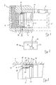
- Fig. 1 shows schematically a cold chamber die casting machine, in whose circular cylindrical casting cylinder 1, a piston 3 between an advanced position shown in FIG. 1 with solid lines and a 3 'dash-dotted retracted position is displaced.
- molten metal e.g. Aluminum melt
- the molten metal is pressed at high pressure via a sprue 9 in the injection mold, not shown.
- the piston 3 carries at its high-pressure end a fixed in two directions of movement sealing ring 11, the casting chamber 7 to Fill opening 5 seals off.
- the sealing ring 11 has, as shown in FIG. 2, a both axially and radially continuous step slot 13, which allows radial expansion of the sealing ring 11 due to inherent elasticity, so that the sealing ring 11 with an outer abutment annular surface 15 on the inner shell 17 of the casting cylinder. 1 biased due to its own radial elasticity, as best shown in FIG. 3.
- the extending in the circumferential direction in achsnormalen levels stages 19 at the step slot 13 forming ends of the annular body 21 of the sealing ring 11 abut each other and seal the step slot 13 axially.
- the piston 3 contains at 22 indicated, connected to a not-shown cooling system cooling channels, via which the piston 3 is cooled to a low temperature based on the temperature of the molten metal, for example 40 ° - 60 ° C. Details of the construction of a suitable in the context of the invention, cooled piston are also in EP 0 423 413 A2 as well as in EP 0 525 229 A1 described.
- the inner shell 17 of the casting cylinder 1 radially resilient annular body 21 of the sealing ring 11 includes near its low-pressure side axial end a circumferential groove 23 into which engages a radially projecting from the outer periphery of the piston 3, circumferential projection 25 and the sealing ring 11 in both displacement directions of the piston. 3 fixed on this.
- On the axially to the high pressure side of the piston 3 side of the annular groove 23 of the annular body 21 is dimensioned so that its inner shell 27 together with the outer shell of the piston 3 defines an annular gap 29 which is open to the high pressure side of the casting chamber.
- the investment annular surface 15 intended to bear against the inner jacket 17 of the casting cylinder 1 is smaller in the axial direction than the inner jacket surface 27 exposed to the melt pressure in the annular gap 29, so that a reinforcement of the radial compressive force acting on the abutment annular surface 15 results.
- This design of the sealing ring 11 and the piston 3 also allows lubrication of the piston during retraction in its position 3 '. It is known to fill not only the molten metal via the filling opening 5 of the casting cylinder 1 (FIG.
- the small axial height of the abutment annular surface 15 compared to the axial overall length of the annular body 21 facilitates initial grinding and fitting of the sealing ring 11 to the cylindrical surface 17.
- the frustoconical lateral surface 31 extends close to the high pressure end of the annular body 21, so that the Einschleif and fitting phase of the sealing ring 11 already after a few Casting cycles is completed.
- the abutment annular surface 15 becomes wider due to the wear.
- the outer shell of the annular body 21 on the low pressure side of the abutment annular surface 15 may also have a different contour, for example, a stepped, reduced in diameter cylinder contour, as indicated by dashed lines at 35 in Fig. 3.
- the contour 35 extends in the illustrated example to the low-pressure end of the annular body 21, but may also end in the ring body before this end and form a Schmierstofftechnischnut on the outer surface of the annular body 21.
- the annular recess 33 can be omitted here, as in the previously explained variants.
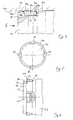
- FIGS. 4 and 5 show a variant of a in a casting cylinder 1 a displaceable piston 3a, which carries a sealing ring 11 a in the region of its high-pressure side end face.
- the sealing ring 11 a is provided according to the above-described sealing ring with a stepped slot and has an outer shell contour with a comparatively short in the axial direction abutment annular surface 15 a and a low pressure side subsequent frustoconical and low pressure side tapered outer sheath portion 31 a, as has been explained above , Also in this variant closes to the annular body 21 a of the sealing ring 1 1 a to the ring body 21 a and the inner shell 17 a through open ring recess 33 a.
- the sealing behavior, the Einschleif and the Lubricating behavior during retraction of the piston 3a thus corresponds to the embodiment of FIGS. 1 to 3.
- the piston 3a carries near its high-pressure end at its outer periphery an annular groove 37 into which the annular body 21 a engages over its entire axial length and in which it is fixed axially in both piston movement directions with a certain play.
- the high-pressure end of the piston 3a is arranged on its outer circumference with a plurality, here four, distributed in the circumferential direction , Trough-shaped recesses 39 which extend axially below the inner circumferential surface 27 a and in the bottom 41 of the ring body 21 a receiving annular recess 37 end. Via the recesses 39, molten metal flows into an annular gap 29 a formed between the bottom 41 of the annular recess 37 and the inner jacket 27 a of the annular body 21 a and increases the radial sealing pressure of the sealing ring 11 a.
- the annular gap 29a Since the annular gap 29a is connected to the casting chamber only via the circumferentially limited recesses 39, the annular gap 29a contains a melt distribution channel formed by a ring recess 43 of the piston 3a. It is understood that the recesses 39 may be provided wholly or additionally in the sealing ring 11a.
- FIG. 6 shows a variant of the piston of FIGS. 4 and 5, in which the high-pressure-side front end of the piston 3b is designed as a removable cover 47 which is fastened releasably to the piston 3b by means of a threaded projection 45.
- the separating surface 49 of the lid intersects the annular body 21 b of the sealing ring 11 b receiving annular recess 37 b of the piston 3 b and forms the high-pressure side limiting shoulder 51 of this annular recess 37 b.
- the radial height of the boundary shoulder 51 can now be chosen freely, since after removing the cover 47, the sealing ring 11 b can be pulled off axially.
- the design of the sealing ring 1 1 b corresponds to the explained with reference to FIGS. 4 and 5 variant, in which case the recesses 39 b are provided in the lid 47, but also here can extend to below the ring body 21 b.
- the lid 47 is made of a poorer heat-conducting material, such as steel or is thermally insulated by a ceramic coating to the cooling of the molten metal during the casting process in particular into the Nachtikphase in which cavities of the melt to be closed to delay.
Landscapes
- Engineering & Computer Science (AREA)
- Mechanical Engineering (AREA)
- Pistons, Piston Rings, And Cylinders (AREA)
- Encapsulation Of And Coatings For Semiconductor Or Solid State Devices (AREA)
- Forging (AREA)
- Injection Moulding Of Plastics Or The Like (AREA)
- Sealing Devices (AREA)
Abstract
Description
Die Erfindung betrifft einen Dichtring für einen Kolben eines Druckgießzylinders, insbesondere einer Kaltkammer-Druckgießmaschine für Metallschmelze, insbesondere Aluminiumschmelze. Die Erfindung betrifft ferner einen solchen Kolben.The invention relates to a sealing ring for a piston of a pressure casting cylinder, in particular a cold chamber die casting machine for molten metal, in particular aluminum melt. The invention further relates to such a piston.
Der Kolben einer Kaltkammer-Druckgießmaschine und insbesondere der Dichtring eines solchen Kolbens ist einerseits hohen Drücken bei vergleichsweise hohen Temperaturen der Metallschmelze ausgesetzt, so dass die Metallschmelze während des Gießhubs des Kolbens unter und hinter den Dichtring getrieben wird. Andererseits erstarrt die Schmelze dort aufgrund der vergleichsweise niedrigen Temperatur des ansonsten gekühlten Kolbens. Der Kolben und insbesondere sein Dichtring sind deshalb im Betrieb sehr hohen Beanspruchungen ausgesetzt die seine Lebensdauer verkürzen, was sich nachteilig auf die Produktivität der Gießmaschine auswirkt.The piston of a cold chamber die casting machine and in particular the sealing ring of such a piston is exposed on the one hand high pressures at relatively high temperatures of the molten metal, so that the molten metal is driven during the casting stroke of the piston under and behind the sealing ring. On the other hand, the melt solidifies there due to the comparatively low temperature of the otherwise cooled piston. The piston and in particular its sealing ring are therefore exposed during operation very high stresses shorten its life, which adversely affects the productivity of the casting machine.
Aus
Aus
Schließlich ist es bekannt, den Kolben in dem Druckgießzylinder mit einem bei der Temperatur der Metallschmelze sich verflüssigenden, bei der Temperatur des gekühlten Kolbens jedoch viskosen oder festen Schmiermittel, z.B. auf einer Wachsbasis oder dergleichen, zumindest in der Druckphase zu schmieren. Das Schmiermittel kann vor dem Einfüllen der Metallschmelze in den Druckgießzylinder eingebracht werden oder aber, wie dies in
Es ist Aufgabe der Erfindung, einen Dichtring für den Kolben einer Druckgießmaschine, insbesondere einer Kaltkammer-Druckgießmaschine zu schaffen, der eine hohe Lebensdauer bei guter Abdichtwirkung hat. Soweit der Dichtring bei einer geschmierten Betriebsweise genutzt wird, soll er die Schmierwirkung unterstützen. Es ist ferner Aufgabe der Erfindung, einen für die Abdichtung mittels des vorstehend erläuterten Dichtrings geeigneten Kolben anzugeben, der die Dichtwirkung des Dichtrings zusätzlich unterstützt.It is an object of the invention to provide a sealing ring for the piston of a die casting machine, in particular a cold chamber die casting machine, which has a long service life with a good sealing effect. As far as the sealing ring is used in a lubricated mode of operation, it should support the lubricating effect. It is a further object of the invention to provide a suitable for sealing by means of the above-described sealing ring piston, which additionally supports the sealing effect of the sealing ring.
Die Erfindung geht von einem Dichtring für einen Kolben eines Druckgießzylinders für Metallschmelze, insbesondere Aluminiumschmelze, des aus
Ein solcher Dichtring kann wegen seines Schlitzes aufgrund inhärenter eigener Vorspannung radial federnd am Innenmantel des Zylinders anliegen. Die Anlagefläche ist, bezogen auf die axiale Gesamtlänge des Ringkörpers, klein. Die dementsprechend große radiale Spreizkraft des Ringkörpers sorgt für einen hohen radialen Anpressdruck an der Anlage-Ringfläche, was die Dichtwirkung verbessert. Aufgrund des hohen radialen Anpressdrucks schleift sich die Anlage-Ringfläche entsprechend der Zylinderform ein, was wiederum die Dichtwirkung des Dichtrings verbessert.Such a sealing ring can bear due to its slot due to inherent inherent bias radially resiliently on the inner surface of the cylinder. The contact surface is, based on the total axial length of the annular body, small. The correspondingly large radial spreading force of the annular body ensures a high radial contact pressure on the contact ring surface, which improves the sealing effect. Due to the high radial contact pressure, the contact ring surface grinds according to the cylindrical shape, which in turn improves the sealing effect of the sealing ring.
Im nicht eingebauten Zustand ist der Außendurchmesser des Dichtrings größer als der Innendurchmesser des Druckgießzylinders, so dass der Dichtring unter Eigenvorspannung in dem Zylinder sitzt. Zumindest der radial innerhalb der Anlage-Ringfläche gelegene Bereich des Innenmantels des Ringkörpers ist dem Metallschmelzedruck ausgesetzt und erhöht, da die Fläche dieses Innenmantelbereichs größer ist als die äußere Anlage-Ringfläche, die radiale Anpresskraft, selbst wenn in den niederdruckseitigen Bereichen des zwischen dem Dichtring und dem Kolben verbleibenden Ringspalts die Metallschmelze aufgrund der Kolbenkühlung erstarrt. In den hochdruckseitigen Bereichen dieses Ringspalts bleibt der Metallschmetzedruck wirksam.In the non-installed state, the outer diameter of the sealing ring is greater than the inner diameter of the die-cast cylinder, so that the sealing ring sits under self-bias in the cylinder. At least the region of the inner shell of the annular body which is located radially inside the abutment annular surface is exposed to the metal melt pressure and increases, since the surface of this inner sheath region is larger than the outer abutment annular surface, the radial contact pressure, even if in the low pressure side regions of the between the sealing ring and the remaining annular gap the metal melt solidifies due to the piston cooling. In the high pressure side areas of this annular gap, the metal smear pressure remains effective.
Die zur Niederdruckseite des Dichtrings an die äußere Anlage-Ringfläche axial anschließende, im Durchmesser verkleinerte Außenmantelfläche des Ringkörpers schafft zwischen sich und dem Zylinder einen Ringspalt, in welchen bei geschmiertem Betrieb das in die Gießkammer vor der Metallschmelze eingeführte Schmiermittel während des Druckvorschubs des Kolbens an der äußeren Anlage-Ringfläche vorbei eintreten kann. Beim Zurückziehen des Kolbens enthält dieser zwischen Ringkörper und Zylinder gebildete Spalt Schmiermittel, welches bei der Rückzugsbewegung von dem radial elastischen Dichtring am Innenmantel des Zylinders verstrichen wird und so die Rückzugsbewegung des Kolbens schmiert. In dieser Phase des Betriebs ist das in dem Ringspalt enthaltene Schmiermittel aufgrund der niedrigen Temperatur des gekühlten Kolbens in aller Regel verfestigt.
Zweckmäßigerweise erstreckt sich der im Durchmesser verkleinerte äußere Ringflächenabschnitt des Ringkörpers bis an dessen niederdruckseitiges axiales Ende, ist also zur Niederdruckseite des Kolbens hin offen. Auf diese Weise kann der auf der Niederdruckseite des Dichtrings in aller Regel gleichfalls einen Ringspalt zwischen sich und dem Zylinder bildende Kolben zur Aufnahme eines den Dichtring schmierenden Schmiermittelvorrats ausgenutzt werden.The low-pressure side of the sealing ring to the outer abutment annular surface axially adjacent, reduced in diameter outer surface of the annular body creates between itself and the cylinder an annular gap in which in lubricated operation introduced into the casting chamber before the molten metal lubricant during the pressure feed of the piston on the outer plant annular surface can enter past. Upon retraction of the piston, this gap formed between the annular body and the cylinder contains lubricant which, in the retraction movement, passes from the radially elastic sealing ring on the inner surface of the cylinder and thus lubricates the return movement of the piston. In this phase of operation, the lubricant contained in the annular gap is usually solidified due to the low temperature of the cooled piston.
Appropriately, the reduced in diameter outer annular surface portion of the annular body extends to its low-pressure side axial end, so it is open to the low pressure side of the piston. In this way, on the low-pressure side of the sealing ring as a rule also an annular gap between itself and the cylinder forming piston for receiving a sealing ring lubricating lubricant supply can be exploited.
In einer bevorzugten Ausgestaltung hat der im Durchmesser verkleinerte Ringflächenabschnitt des Ringkörpers zumindest angenähert Kegelstumpfform und verjüngt sich zum niederdruckseitigen axialen Ende des Ringraums hin. Diese Gestaltung hat den Vorteil, dass die äußere Anlage-Ringfläche im Neuzustand des Dichtrings in axialer Richtung sehr schmal gehalten werden kann, so dass sich der Dichtring anfänglich bereits nach einigen wenigen Gießzyklen der Form des Druckgießzylinders entsprechend einschleift. Aufgrund der Kegelstumpfform vergrößert sich jedoch die äußere Anlage-Ringfläche mit zunehmendem Verschleiß, was die Verschleißgeschwindigkeit mindert.In a preferred embodiment, the reduced in diameter annular surface portion of the annular body has at least approximately truncated cone shape and tapers towards the low pressure side axial end of the annular space. This design has the advantage that the outer abutment annular surface in the new condition of the sealing ring can be kept very narrow in the axial direction, so that the sealing ring already initially grinds in accordance with the shape of the die-casting cylinder after a few casting cycles. Due to the truncated cone shape, however, the increased outer abutment ring surface with increasing wear, which reduces the wear rate.
Der Kolben ist zweckmäßigerweise so ausgestaltet, dass er die vorstehend erläuterten Vorteile des Dichtrings unterstützt. Bevorzugt bildet deshalb die der Metallschmelze auszusetzende innere Ringfläche des Innenmantels des Ringkörpers zusammen mit dem Außenmantel des Kolbens einen auf der Hochdruckseite des Ringkörpers zur Druckkammer des Druckgießzylinders offenen Ringspalt. Um den hochdruckseitigen Zutritt für Metallschmelze zu dem Ringspalt zwischen Dichtring und Kolben möglichst groß halten zu können, hat der Kolben bevorzugt einen radial abstehenden Ringvorsprung, der zur axialen Fixierung des Ringkörpers an dem Kolben in eine auf der Niederdruckseite des Ringspalts im Innenmantel des Ringkörpers angeordnete Nut eingreift. Die Fixierungsorgane sind damit auf der Niederdruckseite des für die radiale Dichtkrafterhöhung und Abdichtung vorgesehenen Ringspalts angeordnet. Es versteht sich, dass alternativ die Nut auch am Kolben und der Ringvorsprung am Ringkörper vorgesehen sein kann.The piston is expediently designed so that it supports the above-explained advantages of the sealing ring. Preferably, therefore, the metal ring to be expelled inner annular surface of the inner shell of the annular body together with the outer surface of the piston forms an open on the high pressure side of the annular body to the pressure chamber of the die-casting cylinder annular gap. In order to keep the high-pressure side access to molten metal to the annular gap between the sealing ring and piston as large as possible, the piston preferably has a radially projecting annular projection, which is arranged for axially fixing the annular body on the piston in a arranged on the low pressure side of the annular gap in the inner shell of the annular body groove intervenes. The fixing organs are thus arranged on the low-pressure side of the radial sealing force increase and sealing provided annular gap. It is understood that alternatively the groove can also be provided on the piston and the annular projection on the annular body.
Alternativ kann der Kolben an seinem Außenmantel aber auch eine Ringsparung aufweisen, in die der Ringkörper zu seiner axialen Fixierung und Bildung des Ringspalts insbesondere mit seiner gesamten axialen Länge eingreift. Für den hochdruckseitigen Zutritt der Metallschmelze zu diesem Ringspalt weist der Kolben bevorzugt mehrere in Umfangsrichtung verteilt angeordnete, vom hochdruckseitigen Stirnende des Kolbens ausgehende und in den Ringspalt mündende Aussparungen auf. Zweckmäßigerweise ist bei dieser Ausgestaltung in einer der beiden den Ringspalt bildenden Mantelflächen, insbesondere im Außenmantel der Ringaussparung des Kolbens, eine umlaufende Schmelzeverteilernut vorgesehen, die die über die axialen Aussparungen eintretende Metallschmelze in Umfangsrichtung gleichmäßig verteilt, bevor die Schmelze infolge der Kolbenkühlung erstarrt.Alternatively, however, the piston can also have a ring recess on its outer jacket into which the annular body engages, in particular with its entire axial length, for its axial fixing and formation of the annular gap. For the high-pressure side access of the molten metal to this annular gap, the piston preferably has a plurality of recesses distributed in the circumferential direction and extending from the high-pressure-side front end of the piston and opening into the annular gap. Appropriately, in this embodiment, in one of the two annular surfaces forming the annular gap, in particular in the outer shell of the annular recess of the piston, a circumferential melt distribution groove is provided which evenly distributed over the axial recesses molten metal in the circumferential direction before the melt solidifies due to the piston cooling.
Der geschlitzte Dichtring kann ggf. über die hochdruckseitige Stirn des Kolbens in die ihm zugeordnete Ringaussparung des Kolbens hineingehoben werden. Diese Montageart kann im Einzelfall aber bedingen, dass der Durchmesser der hochdruckseitigen Stirn vergleichsweise klein ist, um den Dichtring ohne bleibende. Deformation über die Stirn hinwegheben zu können. Dies kann sich nachteilig auf die Lebensdauer des Dichtrings auswirken, da sich der Innendurchmesser des radial elastischen Dichtrings bei Abnutzung vergrößert und er über die Stirn des Kolbens rutschen kann. Dieser Nachteil wird vermieden, wenn die hochdruckseitige Stirn des Kolbens als abnehmbarer, insbesondere abschraubbarer Deckel ausgebildet ist, dessen Trennfläche in der den Ringkörper haltenden Ringaussparung endet. Bei einer solchen Ausgestaltung kann der Durchmesser des die Ringaussparung begrenzenden Deckels vergleichsweise groß bemessen sein.If necessary, the slotted sealing ring can be pushed into the ring recess of the piston assigned to it via the high-pressure-side end of the piston. However, this type of mounting may require in individual cases that the diameter of the high-pressure side end is comparatively small in order to prevent the sealing ring from becoming permanent. To be able to lift deformation over the forehead. This can adversely affect the life of the sealing ring, since the inner diameter of the radially elastic sealing ring increases in wear and it can slip over the front of the piston. This disadvantage is avoided if the high-pressure side end of the piston is designed as a removable, in particular unscrewable cover whose dividing surface terminates in the annular recess holding the annular body. In such a configuration, the diameter of the lid limiting the annular recess may be dimensioned comparatively large.
Bevorzugt besteht der Deckel aus einem schlecht, zumindest aber schlechter wärmeleitenden Material, wie z.B. Stahl, als der anschließende Bereich des Kolbens, oder er ist mit Keramikmaterial beschichtet. Selbst wenn der restliche Kolben zur Optimierung seiner Kühlung aus besser wärmeleitendem Material besteht wird auf diese Weise verhindert, dass die in der Gießkammer befindliche Metallschmelze vor Abschluss der Druckphase, insbesondere auch vor Abschluss der Nachdruckphase, erstarrt.Preferably, the lid is made of a poor, but at least poor, heat-conducting material, such as e.g. Steel, as the adjoining area of the piston, or it is coated with ceramic material. Even if the remaining piston to optimize its cooling consists of better heat-conducting material is prevented in this way that the metal melt located in the casting chamber before the completion of the printing phase, especially before completion of the emphasis phase, solidifies.
Wenngleich der Außendurchmesser des Kolbens auf der Niederdruckseite des Dichtrings in aller Regel zum Zylinder hin bereits einen zur Aufnahme von Schmiermittel geeigneten Ringspalt bildet, so ist doch bevorzugt direkt anschließend an das niederdruckseitige Ende des Ringkörpers des Dichtrings im Außenmantel des Kolbens eine zum Zylinderinnenmantel und zum Ringkörper hin offene Ringaussparung zur Bildung eines Schmiermittelraums vorgesehen, um eine größere Menge Schmiermittel für den Rückzughub des Kolbens speichern zu können.Although the outer diameter of the piston on the low pressure side of the sealing ring usually forms an annular gap suitable for receiving lubricant, so it is preferred directly after the low pressure end of the annular body of the sealing ring in the outer jacket of the piston to the cylinder inner shell and the annular body provided open annular recess for forming a lubricant space to store a larger amount of lubricant for the return stroke of the piston can.
Im Folgenden wird die Erfindung anhand einer Zeichnung näher erläutert. Hierbei zeigt:
- Fig. 1 einen schematischen Axiallängsschnitt durch den Druckgießzylinder einer Kaltkammer-Druckgießmaschine mit einem Kolben und einem zum hochdruckseitigen Ende des Kolbens angeordneten Dichtring gemäß der Erfindung;
- Fig. 2 eine Detailansicht des Dichtrings, gesehen in Richtung eines Pfeils II;
- Fig. 3 eine vergrößerte Detailansicht des Kolbenbereichs der Druckgießmaschine aus Fig. 1;
- Fig. 4 eine Detailansicht einer Variante von Kolben und Dichtring;
- Fig. 5 eine Stirnansicht des Kolbens, gesehen in Richtung eines Pfeils V in Fig. 4 und
- Fig. 6 eine weitere Variante des Kolbens aus Fig. 4.
- 1 shows a schematic Axiallängsschnitt through the die cylinder of a cold chamber die casting machine with a piston and a high-pressure end of the piston arranged sealing ring according to the invention.
- FIG. 2 shows a detailed view of the sealing ring, seen in the direction of an arrow II; FIG.
- FIG. 3 is an enlarged detail view of the piston portion of the die casting machine of FIG. 1; FIG.
- 4 shows a detailed view of a variant of piston and sealing ring;
- Fig. 5 is an end view of the piston, as seen in the direction of arrow V in Fig. 4 and
- 6 shows a further variant of the piston from FIG. 4.
Fig. 1 zeigt schematisch eine Kaltkammer-Druckgießmaschine, in deren kreiszylindrischem Gießzylinder 1 ein Kolben 3 zwischen einer in Fig. 1 mit vollen Linien dargestellten vorgeschobenen Position und einer bei 3' strichpunktiert dargestellten zurückgezogenen Position verschiebbar ist. In der zurückgezogenen Position wird über eine Einfüllöffnung 5 Metallschmelze, z.B. Aluminiumschmelze, in die durch den Kolben 3 und den Gießzylinder 1 begrenzte Gießkammer 7 eingefüllt und beim Vorschieben des Kolbens 3 wird die Metallschmelze mit hohem Druck über einen Angusskanal 9 in die nicht näher dargestellte Spritzgussform gedrückt.Fig. 1 shows schematically a cold chamber die casting machine, in whose circular
Der Kolben 3 trägt an seinem hochdruckseitigen Ende einen in beiden Bewegungsrichtungen fixierten Dichtring 11, der die Gießkammer 7 zur Einfüllöffnung 5 hin abdichtet. Der Dichtring 11 hat, wie Fig. 2 zeigt, einen sowohl axial als auch radial durchgehenden Stufenschlitz 13, der radiales Aufweiten des Dichtrings 11 aufgrund von Eigenelastizität erlaubt, so dass der Dichtring 11 mit einer äußeren Anlage-Ringfläche 15 am Innenmantel 17 des Gießzylinders 1 aufgrund seiner eigenen radialen Elastizität vorgespannt anliegt, wie dies am besten Fig. 3 zeigt. Die in Umfangsrichtung in achsnormalen Ebenen verlaufenden Stufen 19 an den den Stufenschlitz 13 bildenden Enden des Ringkörpers 21 des Dichtrings 11 liegen aneinander an und dichten den Stufenschlitz 13 axial ab. Einzelheiten eines derartigen Stufenschlitzes sind in
Der am Innenmantel 17 des Gießzylinders 1 radial elastisch anliegende Ringkörper 21 des Dichtrings 11 enthält nahe seines niederdruckseitigen axialen Endes eine Umfangsnut 23, in die ein vom Außenumfang des Kolbens 3 radial abstehender, umlaufender Vorsprung 25 eingreift und den Dichtring 11 in beiden Verschieberichtungen des Kolbens 3 an diesem fixiert. Auf der axial zur Hochdruckseite des Kolbens 3 hin gelegenen Seite der Ringnut 23 ist der Ringkörper 21 so bemessen, dass sein Innenmantel 27 zusammen mit dem Außenmantel des Kolbens 3 einen Ringspalt 29 begrenzt, der zur Hochdruckseite der Gießkammer hin offen ist. Beim Vorschieben des Kolbens 3 während der Druckphase des Gießvorgangs wird Metallschmelze in den Ringspalt 29 hineingedrückt, wo sie die auf die Anlage-Ringfläche 15 wirkende radiale Vorspannkraft des Ringkörpers 21 zur Verbesserung der Dichtwirkung erhöht.The
Die zur Anlage am Innenmantel 17 des Gießzylinders 1 bestimmte Anlage-Ringfläche 15 ist in axialer Richtung kleiner als die dem Schmelzdruck in dem Ringspalt 29 ausgesetzte Innenmantelfläche 27, so dass sich eine Verstärkung der auf die Anlage-Ringfläche 15 wirkenden radialen Druckkraft ergibt.The investment
Ausgehend von der vergleichsweise kleinen Anlage-Ringfläche 15 verjüngt sich der zur Niederdruckseite hin anschließende Außenmantelbereich 31 des Ringkörpers 21 kegelstumpfförmig, so dass der auf diese Weise entstehende keilringförmige Ringspalt 32 in einer sowohl zum Innenmantel 17 als auch zum Ringkörper 21 hin offenen Ringaussparung 33 des Kolbens 3 mündet. Diese Gestaltung des Dichtrings 11 und des Kolbens 3 erlaubt auch eine Schmierung des Kolbens beim Zurückziehen in dessen Position 3'. Es ist bekannt, über die Einfüllöffnung 5 des Gießzylinders 1 (Fig. 1) nicht nur die Metallschmelze einzufüllen, sondern auch eine gewisse Menge an viskosem oder festem Schmiermittel, welches sich bei Kontakt mit der Metallschmelze verflüssigt und die Vorschubbewegung des Kolbens 3 während der Gießphase schmiert. Ein Teil des Schmiermittels überwindet den Dichtring 11 und gelangt auf die gekühlte Niederdruckseite, wo es sich in der Ringaussparung 33 und in dem Keilspalt 32 zwischen dem kegelstumpfförmigen Abschnitt 31 und dem Innenmantel 17 sammelt und aufgrund der niedrigen Temperatur des gekühlten Kolbens 3 erstarrt. Beim Zurückziehen des Kolbens 3 in die Position 3' verstreicht der radial elastische Dichtring 11 das Schmiermittel entlang des Innenmantels 17 und schmiert die Rückzugbewegung des Kolbens.Starting from the comparatively small abutment
Die verglichen mit der axialen Gesamtlänge des Ringkörpers 21 geringe axiale Höhe der Anlage-Ringfläche 15 erleichtert anfängliches Einschleifen und Anpassen des Dichtrings 11 an die Zylinderfläche 17. Zweckmäßigerweise erstreckt sich die kegelstumpfförmige Mantelfläche 31 bis nahe an das hochdruckseitige Stirnende des Ringkörpers 21, so dass die Einschleif-und Anpassphase des Dichtrings 11 bereits nach einigen wenigen Gießzyklen abgeschlossen ist. Zum Ende der Lebensdauer des Dichtrings hin wird die Anlage-Ringfläche 15 aufgrund der Abnutzung breiter.The small axial height of the abutment
Es versteht sich, dass der Außenmantel des Ringkörpers 21 auf der Niederdruckseite der Anlage-Ringfläche 15 auch eine andere Kontur haben kann, beispielsweise eine stufenförmige, im Durchmesser verkleinerte Zylinderkontur, wie sie bei 35 in Fig. 3 gestrichelt angedeutet ist. Die Kontur 35 erstreckt sich im dargestellten Beispiel bis an das niederdruckseitige Ende des Ringkörpers 21, kann aber auch in dem Ringkörper vor diesem Ende enden und am Außenmantel des Ringkörpers 21 eine Schmiermittelspeichernut bilden. Die Ringausnehmung 33 kann hier, wie auch bei den vorangegangen erläuterten Varianten, entfallen.It is understood that the outer shell of the
Im Folgenden werden Varianten der anhand der Fig. 1 bis 3 erläuterten Kaltkammer-Spritzgießmaschine beschrieben. Gleichwirkende Komponenten sind mit den Bezugszahlen der Fig. 1 bis 3 bezeichnet und zur Unterscheidung mit einem Buchstaben versehen. Zur Erläuterung des Aufbaus, der Wirkungsweise und evtl. Varianten wird auf die Beschreibung der Fig. 1 bis 3 Bezug genommen.In the following, variants of the described with reference to FIGS. 1 to 3 cold chamber injection molding machine will be described. Equivalent components are denoted by the reference numerals of FIGS. 1 to 3 and provided with a letter for distinction. To explain the structure, the mode of action and possibly variants, reference is made to the description of FIGS. 1 to 3.
Die Fig. 4 und 5 zeigen eine Variante eines in einem Gießzylinder 1 a verschiebbaren Kolbens 3a, der im Bereich seines hochdruckseitigen Stirnendes einen Dichtring 11 a trägt. Der Dichtring 11 a ist entsprechend dem vorstehend erläuterten Dichtring mit einem Stufenschlitz versehen und hat eine Außenmantelkontur mit einer vergleichsweise in axialer Richtung kurzen Anlage-Ringfläche 15a und einem niederdruckseitig daran anschließenden kegelstumpfförmigen und zur Niederdruckseite hin sich verjüngenden Außenmantelbereich 31 a, wie dies vorangegangen erläutert wurde. Auch in dieser Variante schließt an den Ringkörper 21 a des Dichtrings 1 1 a eine zum Ringkörper 21 a und zum Innenmantel 17a hin offene Ringaussparung 33a an. Das Abdichtverhalten, das Einschleifverhalten und das Schmierverhalten beim Zurückziehen des Kolbens 3a entspricht damit dem Ausführungsbeispiel der Fig. 1 bis 3.4 and 5 show a variant of a in a casting cylinder 1 a
Unterschiedlich zur Ausführungsform der Fig. 1 bis 3 ist in erster Linie die axiale Fixierung des Dichtrings 11 a am Kolben 3a. Der Kolben 3a trägt nahe seines hochdruckseitigen Endes an seinem Außenumfang eine Ringnut 37, in die der Ringkörper 21 a über seine gesamte axiale Länge eingreift und in der er in beiden Kolbenbewegungsrichtungen mit einem gewissen Spiel axial fixiert ist.Different from the embodiment of FIGS. 1 to 3 is primarily the axial fixation of the sealing ring 11 a on the
Um den über die gesamte axiale Höhe des Ringkörpers 21 a sich erstreckenden Innenmantel 27a des Ringkörpers 21 a dem Druck der Metallschmelze in der Gießkammer aussetzen zu können, ist das hochdruckseitige Ende des Kolbens 3a an seinem Außenumfang mit mehreren, hier vier, in Umfangsrichtung verteilt angeordneten, rinnenförmigen Aussparungen 39 versehen, die sich axial bis unter die Innenmantelfläche 27a erstrecken und im Boden 41 der den Ringkörper 21 a aufnehmenden Ringaussparung 37 enden. Über die Aussparungen 39 strömt Metallschmelze in einen zwischen dem Boden 41 der Ringaussparung 37 und dem Innenmantel 27a des Ringkörpers 21 a gebildeten Ringspalt 29a und erhöht den radialen Dichtdruck des Dichtrings 11 a. Da der Ringspalt 29a lediglich über die in Umfangsrichtung begrenzten Aussparungen 39 mit der Gießkammer verbunden ist, enthält der Ringspalt 29a einen durch eine Ringaussparung 43 des Kolbens 3a gebildeten Schmelzeverteilungskanal. Es versteht sich, dass die Aussparungen 39 ganz oder zusätzlich auch im Dichtring 11a vorgesehen sein können.In order to expose over the entire axial height of the
Im Ausführungsbeispiel der Fig. 4 und 5 ist die Ringaussparung 37 in einem integralen Bereich des Kolbens 3a vorgesehen. Bei der Montage muss deshalb der Ringkörper 21 a des Dichtrings 1 1 a über die hochdruckseitige Schulter der Ringaussparung 37 hinweggehoben werden, was die maximale radiale Höhe dieser Schulter konstruktiv begrenzt. Mit wachsender Abnutzung des Dichtrings 11a kann dieser dann unter Umständen aus der Aussparung 37 herausrutschen. Um dies zu vermeiden, zeigt Fig. 6 eine Variante des Kolbens der Fig. 4 und 5, bei welchem das hochdruckseitige Stirnende des Kolbens 3b als abnehmbarer, hier mittels eines Gewindeansatzes 45 lösbar an dem Kolben 3b befestigter Deckel 47 ausgebildet ist. Die Trennfläche 49 des Deckels schneidet die den Ringkörper 21 b des Dichtrings 11 b aufnehmende Ringaussparung 37b des Kolbens 3b und bildet die hochdruckseitige Begrenzungsschulter 51 dieser Ringaussparung 37b. Die radiale Höhe der Begrenzungsschulter 51 kann nun frei gewählt werden, da nach dem Abnehmen des Deckels 47 der Dichtring 11 b axial abgezogen werden kann. Die Gestaltung des Dichtrings 1 1 b entspricht der anhand der Fig. 4 und 5 erläuterten Variante, wobei hier die Aussparungen 39b im Deckel 47 vorgesehen sind, sich aber auch hier bis unter den Ringkörper 21 b erstrecken können.In the embodiment of Figs. 4 and 5, the
Während der Kolben 3b zur besseren Kühlung aus gut wärmeleitendem Material, beispielsweise einer Kupferlegierung bestehen kann, besteht der Deckel 47 aus einem schlechter wärmeleitenden Material, beispielsweise Stahl oder ist durch einen keramischen Überzug wärmeisoliert, um die Abkühlung der Metallschmelze während des Gießvorgangs insbesondere bis in die Nachdruckphase, in welcher Hohlräume der Schmelze geschlossen werden sollen, zu verzögern.While the piston 3b may consist of good heat-conducting material, such as a copper alloy for better cooling, the
Es versteht sich, dass die anhand der Fig. 1 bis 3 erläuterten Varianten des Außenmantels des Dichtrings auch bei dem Dichtring der Fig. 4 bis 6 mit Vorteil genutzt werden können.It is understood that the illustrated with reference to FIGS. 1 to 3 variants of the outer jacket of the sealing ring can also be used with advantage in the sealing ring of Fig. 4 to 6.
Claims (13)
- Sealing ring for a piston of a pressure die-casting cylinder for metal melts, in particular aluminium melts, with a radially elastic annular body (21), which comprises an axially and radially continuous slot (13), in particular a slot that is stepped in the circumferential direction of the annular body, characterised in that
the external casing of the annular body (21) close to its high pressure side axial end has a bearing annular surface (15) specifically for bearing against the inner casing surface (17) of the pressure die-casting cylinder (1), the axial length of which is smaller than the axial length of an inner annular surface (27) overlapping axially with said outer bearing annular surface (15) and exposed to the metal melt, and in that on the low pressure side of the outer bearing annular surface (15) an annular surface section (31; 35) adjoins the outer bearing annular surface (15) at least over a partial area of the remaining axial length of the external casing of the annular body (21), the diameter of which section is smaller than the diameter of the outer bearing annular surface (15). - Sealing ring according to claim 1, characterised in that the external annular surface section (31; 35) of reduced diameter extends up to the low pressure side axial end of the annular body (21).
- Sealing ring according to claim 2, characterised in that the annular surface section (31) of reduced diameter has at least an approximately truncated cone shape and tapers towards the low pressure side axial end of the annular body (21).
- Sealing ring according to one of claims 1 to 3, characterised in that the inner casing of the annular body (21), in particular close to its low pressure side axial end, has a peripheral annular recess (23).
- Piston for a compression die-casting cylinder for metal melts, in particular aluminium melts, with a sealing ring (11) secured axially close to the high pressure side piston end according to one of claims 1 to 4, characterised in that the annular surface (27) of the inner sleeve of the ring body (21) to be exposed to the metal melt together with the external casing of the piston (3) forms an annular gap (29) that is open on the high pressure side of the annular body (21) towards the pressure chamber (7) of the compression die-casting cylinder (1).
- Piston according to claim 5, characterised in that it has a radially projecting annular projection (25), which for axially securing the annular body (21) onto the piston (3) engages in an annular groove (23) arranged on the low pressure side of the annular gap (29) in the inner casing (27) of the annular body (21).
- Piston according to claim 5, characterised in that on its external casing it has an annular recess (37) in which the annular body (21a) engages to be fixed axially forming the annular gap (29a), and in that the piston (3a) has several recesses (39) distributed in peripheral direction emerging from the high-pressure side end of the piston (3a) opening into the annular gap (29a).
- Piston according to claim 7, characterised in that in one of the two casing surfaces forming the annular gap (39), in particular of the external casing of the annular recess (37) a peripheral melt distribution groove (43) is arranged.
- Piston according to claim 7 or 8, characterised in that its high-pressure side end is designed as a removable lid (47), in particular one that can be unscrewed, the interface (49) of which ends in the annular recess (37b) holding the annular body (21b).
- Piston according to claim 9, characterised in that the lid (47) is made of a material that conducts heat less well than the adjoining area of the piston (3b).
- Piston according to claim 9 or 10, characterised in that the lid (47) is made of steel or a copper alloy and/or is coated with a ceramic material.
- Piston according to one of claims 5 to 11, characterised in that directly adjoining the low pressure side end of the annular body (21) of the sealing ring (11) in its external casing it has an annular recess (33) that is open towards the cylinder internal casing (17) and to the annular body (21) to form a lubricant chamber.
- Piston according to one of claims 5 to 12, characterised in that in the region of the sealing ring (11) it contains means for cooling the piston.
Applications Claiming Priority (1)
| Application Number | Priority Date | Filing Date | Title |
|---|---|---|---|
| PCT/EP2002/002356 WO2003074214A1 (en) | 2002-03-04 | 2002-03-04 | Sealing ring and piston for a pressure die casting cylinder |
Publications (2)
| Publication Number | Publication Date |
|---|---|
| EP1483074A1 EP1483074A1 (en) | 2004-12-08 |
| EP1483074B1 true EP1483074B1 (en) | 2007-06-13 |
Family
ID=27771816
Family Applications (2)
| Application Number | Title | Priority Date | Filing Date |
|---|---|---|---|
| EP02727355A Expired - Lifetime EP1483074B1 (en) | 2002-03-04 | 2002-03-04 | Sealing ring and piston for a pressure die casting cylinder |
| EP02792752A Withdrawn EP1483075A2 (en) | 2002-03-04 | 2002-11-11 | Plunger for a cold chamber diecasting machine |
Family Applications After (1)
| Application Number | Title | Priority Date | Filing Date |
|---|---|---|---|
| EP02792752A Withdrawn EP1483075A2 (en) | 2002-03-04 | 2002-11-11 | Plunger for a cold chamber diecasting machine |
Country Status (6)
| Country | Link |
|---|---|
| EP (2) | EP1483074B1 (en) |
| AT (1) | ATE364464T1 (en) |
| AU (2) | AU2002257612A1 (en) |
| DE (1) | DE50210331D1 (en) |
| ES (1) | ES2287274T3 (en) |
| WO (2) | WO2003074214A1 (en) |
Cited By (3)
| Publication number | Priority date | Publication date | Assignee | Title |
|---|---|---|---|---|
| DE102009057197B3 (en) * | 2009-11-30 | 2011-05-19 | Oskar Frech Gmbh + Co. Kg | Casting unit for a die casting machine |
| EP2554296A2 (en) | 2011-08-05 | 2013-02-06 | Schmelzmetall AG | Die casting injection piston head |
| KR20190040139A (en) * | 2016-08-29 | 2019-04-17 | 코프로멕 다이 캐스팅 에스.알.엘. 어 소시오 유니코 | The piston of the die casting device |
Families Citing this family (8)
| Publication number | Priority date | Publication date | Assignee | Title |
|---|---|---|---|---|
| DE20309181U1 (en) * | 2003-06-13 | 2004-10-28 | Allper Ag | Multi-part piston for a cold chamber die casting machine |
| DE102005048717A1 (en) * | 2005-10-12 | 2007-04-19 | Allper Ag | Multi-part piston for a cold chamber casting machine |
| ITBS20060087A1 (en) * | 2006-04-12 | 2007-10-13 | Copromec S R L | PISTON FOR COLD ROOM DIE CASTING MACHINES |
| BRPI0703362A2 (en) * | 2007-08-15 | 2009-03-31 | W Fischer Tecnica Ltda | cast metal injection piston |
| IT1393329B1 (en) * | 2009-01-21 | 2012-04-20 | Brondolin S P A | PISTON AND SEALING RING FOR DIE CASTING |
| IT1393330B1 (en) * | 2009-01-21 | 2012-04-20 | Brondolin S P A | PISTONS FOR DIE CASTING |
| TW201501838A (en) | 2013-04-04 | 2015-01-16 | Gani Murselaj | Piston for metal die casting |
| DE102014018795A1 (en) * | 2014-12-19 | 2016-06-23 | Gebr. Krallmann Gmbh | Delivery device for a molten metal in an injection molding unit |
Family Cites Families (6)
| Publication number | Priority date | Publication date | Assignee | Title |
|---|---|---|---|---|
| DE1080739B (en) * | 1957-11-16 | 1960-04-28 | Friedr Fingscheidt G M B H | Pistons for die casting machines |
| US4899804A (en) * | 1989-02-21 | 1990-02-13 | Hammerer Norman L | Plunger tip for cold chamber die cast machine |
| DE59010692D1 (en) * | 1989-10-18 | 1997-05-07 | Allper Ag | Pistons, especially for a die casting press |
| ES2095886T3 (en) * | 1991-07-29 | 1997-03-01 | Allper Ag | PISTON, PARTICULARLY TO PUSH LIQUID METAL OUT OF A CAST CYLINDER. |
| JP2517509B2 (en) * | 1992-01-30 | 1996-07-24 | 日本軽金属株式会社 | Hot chamber-plunger for die casting machine injection |
| IT250574Y1 (en) * | 2000-10-13 | 2003-09-24 | Copromec S R L | COLD CHAMBER PISTON FOR DIE CASTING |
-
2002
- 2002-03-04 AU AU2002257612A patent/AU2002257612A1/en not_active Abandoned
- 2002-03-04 DE DE50210331T patent/DE50210331D1/en not_active Expired - Fee Related
- 2002-03-04 AT AT02727355T patent/ATE364464T1/en not_active IP Right Cessation
- 2002-03-04 WO PCT/EP2002/002356 patent/WO2003074214A1/en active IP Right Grant
- 2002-03-04 EP EP02727355A patent/EP1483074B1/en not_active Expired - Lifetime
- 2002-03-04 ES ES02727355T patent/ES2287274T3/en not_active Expired - Lifetime
- 2002-11-11 WO PCT/EP2002/012585 patent/WO2003074211A2/en not_active Application Discontinuation
- 2002-11-11 EP EP02792752A patent/EP1483075A2/en not_active Withdrawn
- 2002-11-11 AU AU2002358495A patent/AU2002358495A1/en not_active Abandoned
Cited By (7)
| Publication number | Priority date | Publication date | Assignee | Title |
|---|---|---|---|---|
| DE102009057197B3 (en) * | 2009-11-30 | 2011-05-19 | Oskar Frech Gmbh + Co. Kg | Casting unit for a die casting machine |
| WO2011064253A1 (en) | 2009-11-30 | 2011-06-03 | Oskar Frech Gmbh + Co. Kg | Casting unit for a die casting machine |
| US9233417B2 (en) | 2009-11-30 | 2016-01-12 | Oskar Frech Gmbh + Co. Kg | Casting unit for a diecasting machine |
| EP2554296A2 (en) | 2011-08-05 | 2013-02-06 | Schmelzmetall AG | Die casting injection piston head |
| DE102011052446A1 (en) | 2011-08-05 | 2013-02-07 | Schmelzmetall Ag | Die-cast piston head |
| KR20190040139A (en) * | 2016-08-29 | 2019-04-17 | 코프로멕 다이 캐스팅 에스.알.엘. 어 소시오 유니코 | The piston of the die casting device |
| KR102402585B1 (en) | 2016-08-29 | 2022-05-26 | 코프로멕 다이 캐스팅 에스.알.엘. 어 소시오 유니코 | piston of die casting machine |
Also Published As
| Publication number | Publication date |
|---|---|
| ATE364464T1 (en) | 2007-07-15 |
| AU2002257612A1 (en) | 2003-09-16 |
| ES2287274T3 (en) | 2007-12-16 |
| WO2003074211A3 (en) | 2004-06-10 |
| EP1483074A1 (en) | 2004-12-08 |
| AU2002358495A8 (en) | 2003-09-16 |
| WO2003074211A2 (en) | 2003-09-12 |
| AU2002358495A1 (en) | 2003-09-16 |
| EP1483075A2 (en) | 2004-12-08 |
| WO2003074214A1 (en) | 2003-09-12 |
| DE50210331D1 (en) | 2007-07-26 |
Similar Documents
| Publication | Publication Date | Title |
|---|---|---|
| EP0423413B1 (en) | Piston, especially for a pressure die casting apparatus | |
| DE4112889C2 (en) | Process for producing a piston head with cooling for a multi-part, articulated piston for internal combustion engines, and piston head produced thereafter | |
| EP1483074B1 (en) | Sealing ring and piston for a pressure die casting cylinder | |
| DE3134768C2 (en) | Piston-cylinder unit for internal combustion piston machines, in particular for gasoline and diesel engines | |
| EP3334918B1 (en) | Piston for an internal combustion engine | |
| DE102005029417A1 (en) | Method for producing a piston for an internal combustion engine | |
| DE3412175A1 (en) | CUP-SHAPED HOUSING OF A SELF-ACTUATING HYDRAULICALLY ADJUSTING VALVE TOLDER FOR INTERNAL COMBUSTION ENGINES WITH OVERHEAD CAMSHAFT | |
| WO2013131937A1 (en) | Cast light metal piston, in particular an aluminium piston | |
| EP2506999B1 (en) | Injection unit for a die-casting machine | |
| DE10058428A1 (en) | Cylinder liner and cylinder block and method of manufacturing the same | |
| EP0255475B1 (en) | Shot sleeve for a pressure die-casting | |
| DE2953435C2 (en) | Die-casting machine for performing a die-casting process with post-compression | |
| DE1097210B (en) | Pistons for internal combustion engines | |
| EP1635973B1 (en) | Piston for a cold chamber die casting machine | |
| DE19621894B4 (en) | Internal combustion engine with piston cooling | |
| EP0901852B1 (en) | Plunger for a hot-chamber die-casting machine | |
| EP0893182B1 (en) | Production method for a cylinder liner of an internal combustion engine | |
| DE4308751A1 (en) | Piston-connecting rod arrangement for internal combustion engines | |
| DE19938075A1 (en) | Press piston for cold chamber die casting machines comprises piston head with base area and piston rod joined to piston head and having bearing areas | |
| DE873185C (en) | Pistons, especially for internal combustion engines | |
| EP3502453B1 (en) | Piston for a reciprocating piston combustion engine | |
| DE19954725A1 (en) | Piston with a connection from a cooling channel to a piston pin bore | |
| EP1439927B1 (en) | Cylinder crankcase having a cylinder sleeve, and casting tool | |
| EP1704319B1 (en) | Cylinder crankcase comprising a cylinder liner | |
| DE2533746A1 (en) | Internal combustion engine piston - has ring insert of harder wearing material accommodated in groove |
Legal Events
| Date | Code | Title | Description |
|---|---|---|---|
| PUAI | Public reference made under article 153(3) epc to a published international application that has entered the european phase |
Free format text: ORIGINAL CODE: 0009012 |
|
| 17P | Request for examination filed |
Effective date: 20041001 |
|
| AK | Designated contracting states |
Kind code of ref document: A1 Designated state(s): AT BE CH CY DE DK ES FI FR GB GR IE IT LI LU MC NL PT SE TR |
|
| AX | Request for extension of the european patent |
Extension state: AL LT LV MK RO SI |
|
| GRAP | Despatch of communication of intention to grant a patent |
Free format text: ORIGINAL CODE: EPIDOSNIGR1 |
|
| GRAS | Grant fee paid |
Free format text: ORIGINAL CODE: EPIDOSNIGR3 |
|
| GRAA | (expected) grant |
Free format text: ORIGINAL CODE: 0009210 |
|
| AK | Designated contracting states |
Kind code of ref document: B1 Designated state(s): AT BE CH CY DE DK ES FI FR GB GR IE IT LI LU MC NL PT SE TR |
|
| REG | Reference to a national code |
Ref country code: GB Ref legal event code: FG4D Free format text: NOT ENGLISH |
|
| REG | Reference to a national code |
Ref country code: CH Ref legal event code: EP |
|
| GBT | Gb: translation of ep patent filed (gb section 77(6)(a)/1977) |
Effective date: 20070613 |
|
| REG | Reference to a national code |
Ref country code: IE Ref legal event code: FG4D Free format text: LANGUAGE OF EP DOCUMENT: GERMAN |
|
| REF | Corresponds to: |
Ref document number: 50210331 Country of ref document: DE Date of ref document: 20070726 Kind code of ref document: P |
|
| PG25 | Lapsed in a contracting state [announced via postgrant information from national office to epo] |
Ref country code: SE Free format text: LAPSE BECAUSE OF FAILURE TO SUBMIT A TRANSLATION OF THE DESCRIPTION OR TO PAY THE FEE WITHIN THE PRESCRIBED TIME-LIMIT Effective date: 20070913 |
|
| ET | Fr: translation filed | ||
| REG | Reference to a national code |
Ref country code: CH Ref legal event code: NV Representative=s name: A. BRAUN, BRAUN, HERITIER, ESCHMANN AG PATENTANWAE |
|
| NLV1 | Nl: lapsed or annulled due to failure to fulfill the requirements of art. 29p and 29m of the patents act | ||
| REG | Reference to a national code |
Ref country code: ES Ref legal event code: FG2A Ref document number: 2287274 Country of ref document: ES Kind code of ref document: T3 |
|
| REG | Reference to a national code |
Ref country code: IE Ref legal event code: FD4D |
|
| PG25 | Lapsed in a contracting state [announced via postgrant information from national office to epo] |
Ref country code: IE Free format text: LAPSE BECAUSE OF FAILURE TO SUBMIT A TRANSLATION OF THE DESCRIPTION OR TO PAY THE FEE WITHIN THE PRESCRIBED TIME-LIMIT Effective date: 20070613 Ref country code: NL Free format text: LAPSE BECAUSE OF FAILURE TO SUBMIT A TRANSLATION OF THE DESCRIPTION OR TO PAY THE FEE WITHIN THE PRESCRIBED TIME-LIMIT Effective date: 20070613 Ref country code: PT Free format text: LAPSE BECAUSE OF FAILURE TO SUBMIT A TRANSLATION OF THE DESCRIPTION OR TO PAY THE FEE WITHIN THE PRESCRIBED TIME-LIMIT Effective date: 20071113 |
|
| PLBE | No opposition filed within time limit |
Free format text: ORIGINAL CODE: 0009261 |
|
| STAA | Information on the status of an ep patent application or granted ep patent |
Free format text: STATUS: NO OPPOSITION FILED WITHIN TIME LIMIT |
|
| PG25 | Lapsed in a contracting state [announced via postgrant information from national office to epo] |
Ref country code: DK Free format text: LAPSE BECAUSE OF FAILURE TO SUBMIT A TRANSLATION OF THE DESCRIPTION OR TO PAY THE FEE WITHIN THE PRESCRIBED TIME-LIMIT Effective date: 20070613 Ref country code: GR Free format text: LAPSE BECAUSE OF FAILURE TO SUBMIT A TRANSLATION OF THE DESCRIPTION OR TO PAY THE FEE WITHIN THE PRESCRIBED TIME-LIMIT Effective date: 20070914 |
|
| PGFP | Annual fee paid to national office [announced via postgrant information from national office to epo] |
Ref country code: ES Payment date: 20080328 Year of fee payment: 7 |
|
| 26N | No opposition filed |
Effective date: 20080314 |
|
| PGFP | Annual fee paid to national office [announced via postgrant information from national office to epo] |
Ref country code: IT Payment date: 20080326 Year of fee payment: 7 |
|
| REG | Reference to a national code |
Ref country code: CH Ref legal event code: PFA Owner name: ALLPER AG Free format text: ALLPER AG#WARPELSTRASSE 10#3186 DUEDINGEN (CH) -TRANSFER TO- ALLPER AG#WARPELSTRASSE 10#3186 DUEDINGEN (CH) |
|
| PGFP | Annual fee paid to national office [announced via postgrant information from national office to epo] |
Ref country code: AT Payment date: 20080314 Year of fee payment: 7 |
|
| PGFP | Annual fee paid to national office [announced via postgrant information from national office to epo] |
Ref country code: DE Payment date: 20080229 Year of fee payment: 7 |
|
| BERE | Be: lapsed |
Owner name: ALLPER A.G. Effective date: 20080331 |
|
| PG25 | Lapsed in a contracting state [announced via postgrant information from national office to epo] |
Ref country code: MC Free format text: LAPSE BECAUSE OF NON-PAYMENT OF DUE FEES Effective date: 20080331 |
|
| REG | Reference to a national code |
Ref country code: CH Ref legal event code: PL |
|
| GBPC | Gb: european patent ceased through non-payment of renewal fee |
Effective date: 20080304 |
|
| REG | Reference to a national code |
Ref country code: FR Ref legal event code: ST Effective date: 20081125 |
|
| PG25 | Lapsed in a contracting state [announced via postgrant information from national office to epo] |
Ref country code: CH Free format text: LAPSE BECAUSE OF NON-PAYMENT OF DUE FEES Effective date: 20080331 Ref country code: LI Free format text: LAPSE BECAUSE OF NON-PAYMENT OF DUE FEES Effective date: 20080331 |
|
| PG25 | Lapsed in a contracting state [announced via postgrant information from national office to epo] |
Ref country code: BE Free format text: LAPSE BECAUSE OF NON-PAYMENT OF DUE FEES Effective date: 20080331 Ref country code: FI Free format text: LAPSE BECAUSE OF FAILURE TO SUBMIT A TRANSLATION OF THE DESCRIPTION OR TO PAY THE FEE WITHIN THE PRESCRIBED TIME-LIMIT Effective date: 20070613 |
|
| PG25 | Lapsed in a contracting state [announced via postgrant information from national office to epo] |
Ref country code: FR Free format text: LAPSE BECAUSE OF NON-PAYMENT OF DUE FEES Effective date: 20080331 |
|
| PG25 | Lapsed in a contracting state [announced via postgrant information from national office to epo] |
Ref country code: GB Free format text: LAPSE BECAUSE OF NON-PAYMENT OF DUE FEES Effective date: 20080304 |
|
| PG25 | Lapsed in a contracting state [announced via postgrant information from national office to epo] |
Ref country code: CY Free format text: LAPSE BECAUSE OF FAILURE TO SUBMIT A TRANSLATION OF THE DESCRIPTION OR TO PAY THE FEE WITHIN THE PRESCRIBED TIME-LIMIT Effective date: 20070613 |
|
| PG25 | Lapsed in a contracting state [announced via postgrant information from national office to epo] |
Ref country code: AT Free format text: LAPSE BECAUSE OF NON-PAYMENT OF DUE FEES Effective date: 20090304 |
|
| PG25 | Lapsed in a contracting state [announced via postgrant information from national office to epo] |
Ref country code: DE Free format text: LAPSE BECAUSE OF NON-PAYMENT OF DUE FEES Effective date: 20091001 |
|
| REG | Reference to a national code |
Ref country code: ES Ref legal event code: FD2A Effective date: 20090305 |
|
| PG25 | Lapsed in a contracting state [announced via postgrant information from national office to epo] |
Ref country code: LU Free format text: LAPSE BECAUSE OF NON-PAYMENT OF DUE FEES Effective date: 20080304 Ref country code: ES Free format text: LAPSE BECAUSE OF NON-PAYMENT OF DUE FEES Effective date: 20090305 |
|
| PG25 | Lapsed in a contracting state [announced via postgrant information from national office to epo] |
Ref country code: TR Free format text: LAPSE BECAUSE OF FAILURE TO SUBMIT A TRANSLATION OF THE DESCRIPTION OR TO PAY THE FEE WITHIN THE PRESCRIBED TIME-LIMIT Effective date: 20070613 |
|
| PG25 | Lapsed in a contracting state [announced via postgrant information from national office to epo] |
Ref country code: IT Free format text: LAPSE BECAUSE OF NON-PAYMENT OF DUE FEES Effective date: 20090304 |