EP1483015B1 - Medizinische vorrichtung - Google Patents
Medizinische vorrichtung Download PDFInfo
- Publication number
- EP1483015B1 EP1483015B1 EP03708339A EP03708339A EP1483015B1 EP 1483015 B1 EP1483015 B1 EP 1483015B1 EP 03708339 A EP03708339 A EP 03708339A EP 03708339 A EP03708339 A EP 03708339A EP 1483015 B1 EP1483015 B1 EP 1483015B1
- Authority
- EP
- European Patent Office
- Prior art keywords
- medical device
- electrode
- housing
- control circuit
- aperture
- Prior art date
- Legal status (The legal status is an assumption and is not a legal conclusion. Google has not performed a legal analysis and makes no representation as to the accuracy of the status listed.)
- Expired - Lifetime
Links
- 238000012360 testing method Methods 0.000 claims abstract description 10
- 230000007246 mechanism Effects 0.000 claims abstract description 8
- 238000003780 insertion Methods 0.000 claims abstract description 3
- 230000037431 insertion Effects 0.000 claims abstract description 3
- 238000001514 detection method Methods 0.000 claims description 9
- 238000002680 cardiopulmonary resuscitation Methods 0.000 claims description 3
- 230000008859 change Effects 0.000 claims description 3
- 230000004044 response Effects 0.000 claims description 2
- 230000004913 activation Effects 0.000 abstract description 4
- 239000003990 capacitor Substances 0.000 abstract description 2
- 208000010496 Heart Arrest Diseases 0.000 description 5
- 230000035939 shock Effects 0.000 description 5
- 208000003663 ventricular fibrillation Diseases 0.000 description 5
- 206010003119 arrhythmia Diseases 0.000 description 4
- 230000006793 arrhythmia Effects 0.000 description 4
- 238000010586 diagram Methods 0.000 description 3
- 230000006866 deterioration Effects 0.000 description 2
- 238000004806 packaging method and process Methods 0.000 description 2
- 230000001681 protective effect Effects 0.000 description 2
- 230000004083 survival effect Effects 0.000 description 2
- 229960003965 antiepileptics Drugs 0.000 description 1
- 238000004891 communication Methods 0.000 description 1
- 230000003111 delayed effect Effects 0.000 description 1
- 238000006073 displacement reaction Methods 0.000 description 1
- 238000000537 electroencephalography Methods 0.000 description 1
- 230000005669 field effect Effects 0.000 description 1
- 238000011065 in-situ storage Methods 0.000 description 1
- 239000002184 metal Substances 0.000 description 1
- 238000012544 monitoring process Methods 0.000 description 1
- 230000002107 myocardial effect Effects 0.000 description 1
- 238000006213 oxygenation reaction Methods 0.000 description 1
- 230000033764 rhythmic process Effects 0.000 description 1
- 238000002560 therapeutic procedure Methods 0.000 description 1
- 238000012549 training Methods 0.000 description 1
- 230000001960 triggered effect Effects 0.000 description 1
- 206010047302 ventricular tachycardia Diseases 0.000 description 1
Images
Classifications
-
- A—HUMAN NECESSITIES
- A61—MEDICAL OR VETERINARY SCIENCE; HYGIENE
- A61N—ELECTROTHERAPY; MAGNETOTHERAPY; RADIATION THERAPY; ULTRASOUND THERAPY
- A61N1/00—Electrotherapy; Circuits therefor
- A61N1/18—Applying electric currents by contact electrodes
- A61N1/32—Applying electric currents by contact electrodes alternating or intermittent currents
- A61N1/38—Applying electric currents by contact electrodes alternating or intermittent currents for producing shock effects
- A61N1/39—Heart defibrillators
- A61N1/3904—External heart defibrillators [EHD]
- A61N1/39044—External heart defibrillators [EHD] in combination with cardiopulmonary resuscitation [CPR] therapy
-
- A—HUMAN NECESSITIES
- A61—MEDICAL OR VETERINARY SCIENCE; HYGIENE
- A61N—ELECTROTHERAPY; MAGNETOTHERAPY; RADIATION THERAPY; ULTRASOUND THERAPY
- A61N1/00—Electrotherapy; Circuits therefor
- A61N1/02—Details
- A61N1/08—Arrangements or circuits for monitoring, protecting, controlling or indicating
- A61N2001/083—Monitoring integrity of contacts, e.g. by impedance measurement
Definitions
- the present invention relates to a medical device and in particular to a cardiopulmonary resuscitation device, such as an automated external defibrillator (AED), that is activated by whether or not electrodes, for administering treatment, are associated with the device.
- a cardiopulmonary resuscitation device such as an automated external defibrillator (AED)
- AED automated external defibrillator
- VF ventricular fibrillation
- VT pulseless ventricular tachycardia
- the primary form of therapy is defibrillation, which should be carried out with the minimum of delay in order maximise the patient's chances of survival.
- treatment is delayed, the chances of success of reviving a patient with an otherwise relatively treatable arrhythmia such as VF, declines rapidly with the passage of time.
- an electrocardiogram is taken of the patients experiencing, for example VF, the amplitude and waveform of a patient's electrocardiogram indicates that changes occur in the patient's body such as the depletion of myocardial energy stores and lack of oxygenation.
- Basic life support treatment will not reverse these changes in the patient and can only slow the rate of deterioration. It is a major priority to minimise risk of this deterioration occurring by ensuring that there is the minimum delay between the onset of a cardiac arrest and the administration of treatment by defibrillation using an AED in order to provide a shock to regulate the patient's heart rhythm. Defibrillation may be possible for several minutes after a cardiac arrest occurs but the chances of survival are optimised if treatment is given in the period of around 90 seconds after the onset of cardiac arrest.
- shocks to patients are only given by qualified personnel, such as paramedics specifically trained to use AEDs.
- the training ensures that personnel use such equipment in a way that there is minimal risk off an inappropriate shock being given to a patient. For example, if a patient is not experiencing arrhythmia, and a shock is administered, then the heart rate of an otherwise healthy patient could be disturbed and a cardiac arrest triggered.
- a device according to the preamble of claim 1 is known from US 4 653 474 .
- a medical device having a control circuit adapted to operate one or more electrodes in response to analysis of a patient's condition by the medical device, characterised in that the medical device includes a support for an electrode, whereby when the electrode is associated with the support, the control circuit is deactivated but on removal of the electrode from the support, the control circuit is activated.
- the support or supports comprise apertures in a housing of the medical device.
- the electrodes may be inserted in the apertures thereby interrupting the control circuit either completely or to a substantial extent.
- the circuit is interrupted to a substantial extent, there may be a trickle charge through the electrode so that the medical device remains on standby.
- the condition of the electrode may be monitored by the charge passing through it. This may be by measuring electrical impedance or resistance across the electrode.
- the electrode is contained within a pouch.
- the pouch protects the electrode prior to use.
- the medical device includes an electro-detection circuit for detecting the presence of an electrode or an electrical pouch, which is inserted in the housing.
- the circuit may comprise a switch device that is activated when the pouch is inserted or removed from the housing by displacement of a mechanical element.
- the switch may be in the form of a spring connector in a preferred arrangement.
- the detection circuit may use a field effect sensor to detect the presence of a pouch or electrode between the emitter and sensor.
- the detection circuit may include a light source and detector, with the light source being interrupted when an electrode or pouch is inserted in the housing. When the electrode/pouch is removed from the housing, the detector senses light emission and then acts as a switch to activate the medical device. It is envisaged that a combination of such switching elements may be used so that a back up mechanism can be provided for detection and activation of the device.
- the medical device when the electrode or pouch is removed from the detection circuit, the medical device is switched on ready to deliver treatment, such as a shock via the electrode.
- a self testing diagnostic routine is activated so that self checks can be carried out by the device to ensure that it is functioning correctly prior to use on the patient. It is envisaged that the operation of the removal of the pouch or electrode may directly operate the device or may cause indirect operation of the device by triggering a further prompt mechanism in the device for starting either the self-diagnostic routine or treatment of the patient.
- activation of a switch allows, either directly or indirectly, a power line from a battery system in the device to the control system to become activated. This causes a processor or sub-processor to change its status from idle to active.
- the device can then be activated by switching on, or alternatively a self-test routine may be activated depending on the preset instructions of the device. Whether a self-test occurs or not can be selected by the medical device operator/installer and it may be the case that self-testing is not carried out where there is or is likely to be an ultra emergency, for example the patient is on the point of dying.
- a processor or sub-processor may actively or passively monitor the status of the switching mechanism. A change in status would then alert the processor or sub-processor and would cause power to be activated for the medical device or a self-test may be activated depending again on what the prior programmed instructions are for the device.
- the medical device may be defined as a device that delivers or monitors the condition of a patient by using electrodes.
- the invention is concerned with cardiopulmonary resuscitation devices such as defibrillators or heart monitors, but also the invention is also applicable to other types of devices using electrodes placed on a patient's body such as electrocardigrams (ECGs) or electroencephalogram EEGs.
- ECGs electrocardigrams
- EEGs electroencephalogram EEGs
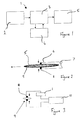
- a circuit for operating a medical device which in this case is a defibrillator, is generally shown as 1.
- the circuit comprises a power source 2 and a switching circuit 3, which switches charge between the power source 2 and capacitors 4 so that charge can be delivered to electrodes 5 which are placed on the patient's chest during treatment.
- the defibrillator has a housing (not shown) with an aperture 6 in the form of a slot in the housing.
- electrical connectors 8 On either side of the opening of the aperture 6 are electrical connectors 8. These may be in the form of metal contacts.
- the connectors 8 are held apart by spring connectors 7 at the end of the aperture opposed to the opening.
- the defibrillator becomes activated by flow of charge from the battery 2. At this point, the defibrillator may be ready for activation or alternatively, depending upon how the defibrillator is set up or programmed, a self-test mechanism may occur.
- FIG. 3 shows a schematic diagram of an electrode inserted within the circuitry of the defibrillator.
- a power source including the battery 2 which in turn is in communication with a processor 10 which can sense the presence of electrode 5 or electrode packaging 9.
- a processor 10 can monitor the condition of the electrode 5. Alternatively, or in addition to monitoring the electrode condition, once the electrode is removed from the defibrillator, it can act activate circuitry to switch the defibrillator on or it can start a pre-check routine to ensure that the defibrillator is in a condition whereby it may deliver charge effectively to the patient.
- the figures refer to a preferred embodiment of the invention. It is may be that there are multiple apertures, each for housing a separate electrode or alternatively, a single aperture may house a number of electrode, with the medical device only being activated when the first or final or any electrode is removed. This arrangement would be particularly useful where pairs of electrodes are used to treat a patient.
- the aperture has integral protective means such as cushioning for protecting the electrode.
Landscapes
- Health & Medical Sciences (AREA)
- Cardiology (AREA)
- Heart & Thoracic Surgery (AREA)
- Engineering & Computer Science (AREA)
- Biomedical Technology (AREA)
- Nuclear Medicine, Radiotherapy & Molecular Imaging (AREA)
- Radiology & Medical Imaging (AREA)
- Life Sciences & Earth Sciences (AREA)
- Animal Behavior & Ethology (AREA)
- General Health & Medical Sciences (AREA)
- Public Health (AREA)
- Veterinary Medicine (AREA)
- Electrotherapy Devices (AREA)
- Surgical Instruments (AREA)
- External Artificial Organs (AREA)
- Eye Examination Apparatus (AREA)
Claims (13)
- Medizinische Vorrichtung mit einer Steuerschaltung, die eine oder mehrere Elektroden in Abhängigkeit von der Analyse eines Patientenzustandes betreiben kann, wobei die medizinische Vorrichtung mit einem Träger für eine Elektrode versehen ist, dadurch gekennzeichnet, daß die Vorrichtung so ausgebildet ist, daß dann, wenn die Elektrode mit dem Träger verbunden wird, die Steuerschaltung ausgeschaltet wird, jedoch dann, wenn die Elektrode von dem Träger entfernt wird, die Steuerschaltung aktiviert wird.
- Medizinische Vorrichtung nach Anspruch 1, dadurch gekennzeichnet, daß die medizinische Vorrichtung einen oder mehrere Träger aufweist, von denen jeder so angeordnet ist, daß er mit einer entsprechenden Elektrode verbunden ist.
- Medizinische Vorrichtung nach Anspruch 1 oder 2, dadurch gekennzeichnet, daß der oder die Träger in einem Gehäuse der medizinischen Vorrichtung Öffnungen aufweisen, die so ausgebildet sind, daß dann, wenn die oder jede Elektrode in die entsprechende Öffnung eingesetzt wird, die Steuerschaltung entweder vollständig oder in einem wesentlichen Ausmaß durch die vorhandene Elektrode oder die vorhandenen Elektroden in der oder jeder Öffnung in dem Gehäuse unterbrochen wird.
- Medizinische Vorrichtung nach Anspruch 3, dadurch gekennzeichnet, daß dann, wenn die Steuerschaltung unterbrochen wird, sie einen Zustand erfährt, der einen Dauerladungsfluß durch die oder jede Elektrode ermöglicht, so daß die medizinische Vorrichtung im Stand-by-Betrieb arbeiten kann.
- Medizinische Vorrichtung nach Anspruch 4 in Verbindung mit einem Monitor, dadurch gekennzeichnet, daß die medizinische Vorrichtung so ausgebildet ist, daß dann, wenn sie sich im Stand-by-Betrieb befindet, der Monitor den Zustand der oder jeder Elektrode als Funktion der sie passierenden Ladung überwacht.
- Medizinische Vorrichtung nach Anspruch 5, dadurch gekennzeichnet, daß der Monitor vorhanden ist, um den elektrischen Schein-Widerstand oder den Widerstand über der Elektrode zu messen.
- Medizinische Vorrichtung nach einem der vorhergehenden Ansprüche, dadurch gekennzeichnet, daß die medizinische Vorrichtung eine Erfassungsschaltung aufweist, die der oder jeder Öffnung in dem Gehäuse zugeordnet ist, und die Erfassungsschaltung das Vorhandensein einer Elektrode oder einer eine Elektrode enthaltenden Tasche feststellt, sobald die Erfassungsschaltung in die Öffnung oder Öffnungen in dem Gehäuse eingesteckt ist.
- Medizinische Vorrichtung nach Anspruch 7, gekennzeichnet durch einen Schalter zum Einschalten des der Steuerschaltung zufließenden Stroms, so daß die medizinische Vorrichtung beim Entfernen der Elektrode / Tasche aktivierbar ist, um den Strom fließen zu lassen.
- Medizinische Vorrichtung nach Anspruch 8, dadurch gekennzeichnet, daß die Erfassungsschaltung eine Lichtquelle und einen Detektor aufweist, wobei letzterer dazu dient, Unterbrechungen der Lichtquelle festzustellen, sobald eine Elektrode / Tasche in das Gehäuse eingesetzt wird, sowie Lichtemission, sobald die Elektrode / Tasche aus dem Gehäuse entfernt wird, wobei der Detektor dann als Schalter arbeitet, um die medizinische Vorrichtung zu aktivieren.
- Medizinische Vorrichtung nach Anspruch 9, dadurch gekennzeichnet, daß sie eine Kombination aus Schaltelementen aufweist, um zu erfassen und die medizinische Vorrichtung zu aktivieren.
- Medizinische Vorrichtung nach einem der vorhergehenden Ansprüche, gekennzeichnet durch einen Selbsttest-Mechanismus, der so ausgebildet ist, daß dann, wenn die Elektrode bzw. die Elektroden aus dem Gehäuse entfernt werden, eine Schaltung in der medizinischen Vorrichtung komplettiert wird, die entweder bewirken kann, daß die medizinische Vorrichtung betriebsbereit gemacht wird oder die den Selbsttest-Mechanismus aktiviert, so daß Überprüfungen durchgeführt werden können, um sicherzustellen, daß die medizinische Vorrichtung richtig arbeitet, und zwar bevor sie an dem Patienten Verwendung findet.
- Medizinische Vorrichtung nach Anspruch 11, dadurch gekennzeichnet, daß der Selbsttest-Mechanismus zur aktiven oder passiven Überwachung der Monitorschaltung in dem medizinischen Gerät als Folge der Entfernung oder des Einsetzens der Elektroden in das Gehäuse dient, und wobei dann eine Änderung des Schaltzustandes einen Prozessor oder Unterprozessor alarmiert, so daß die Steuerschaltung aktiviert werden kann.
- Medizinische Vorrichtung nach einem der vorhergehenden Ansprüche, dadurch gekennzeichnet, daß sie eine Herz-Lungen-Wiederbelebungsvorrichtung ist.
Applications Claiming Priority (3)
| Application Number | Priority Date | Filing Date | Title |
|---|---|---|---|
| GB0205567A GB2386071B (en) | 2002-03-09 | 2002-03-09 | Medical device |
| GB0205567 | 2002-03-09 | ||
| PCT/GB2003/001009 WO2003076005A1 (en) | 2002-03-09 | 2003-03-10 | Medical device |
Publications (2)
| Publication Number | Publication Date |
|---|---|
| EP1483015A1 EP1483015A1 (de) | 2004-12-08 |
| EP1483015B1 true EP1483015B1 (de) | 2009-08-26 |
Family
ID=9932638
Family Applications (1)
| Application Number | Title | Priority Date | Filing Date |
|---|---|---|---|
| EP03708339A Expired - Lifetime EP1483015B1 (de) | 2002-03-09 | 2003-03-10 | Medizinische vorrichtung |
Country Status (7)
| Country | Link |
|---|---|
| EP (1) | EP1483015B1 (de) |
| AT (1) | ATE440638T1 (de) |
| AU (1) | AU2003212519A1 (de) |
| DE (1) | DE60328970D1 (de) |
| ES (1) | ES2330323T3 (de) |
| GB (1) | GB2386071B (de) |
| WO (1) | WO2003076005A1 (de) |
Families Citing this family (2)
| Publication number | Priority date | Publication date | Assignee | Title |
|---|---|---|---|---|
| JP2007521904A (ja) * | 2004-02-10 | 2007-08-09 | コーニンクレッカ フィリップス エレクトロニクス エヌ ヴィ | トレーニングモードを有する体外式除細動器およびその使用方法 |
| GB2491171B (en) | 2011-05-26 | 2016-09-28 | Heartsine Tech Ltd | Testing of defibrillator electrodes |
Family Cites Families (8)
| Publication number | Priority date | Publication date | Assignee | Title |
|---|---|---|---|---|
| US4141351A (en) * | 1977-09-12 | 1979-02-27 | Motorola, Inc. | ECG electrode impedance checking system as for emergency medical service |
| US4576170A (en) * | 1980-07-09 | 1986-03-18 | Micro-Circuits Company | Heart monitor and defibrillator device |
| US5879374A (en) * | 1993-05-18 | 1999-03-09 | Heartstream, Inc. | External defibrillator with automatic self-testing prior to use |
| US5797969A (en) * | 1995-08-01 | 1998-08-25 | Survivalink Corporation | One button lid activated automatic external defibrillator |
| FR2746508B1 (fr) * | 1996-03-21 | 1998-05-22 | Jay Electronique Sa | Installation de detection par reflexion |
| DE19624133A1 (de) * | 1996-06-17 | 1997-12-18 | Jaeger Erich Gmbh | Verfahren und Meßanordnung zum Messen von reizevozierten Potentialen des Gehirns |
| JPH10117228A (ja) * | 1996-10-11 | 1998-05-06 | Uniden Corp | 壁掛け用フック機構を備えた通信装置 |
| US6556864B1 (en) * | 2000-11-13 | 2003-04-29 | Koninklijke Philips Electronics N.V. | Object activated defibrillator |
-
2002
- 2002-03-09 GB GB0205567A patent/GB2386071B/en not_active Expired - Fee Related
-
2003
- 2003-03-10 AT AT03708339T patent/ATE440638T1/de not_active IP Right Cessation
- 2003-03-10 DE DE60328970T patent/DE60328970D1/de not_active Expired - Lifetime
- 2003-03-10 WO PCT/GB2003/001009 patent/WO2003076005A1/en not_active Ceased
- 2003-03-10 AU AU2003212519A patent/AU2003212519A1/en not_active Abandoned
- 2003-03-10 ES ES03708339T patent/ES2330323T3/es not_active Expired - Lifetime
- 2003-03-10 EP EP03708339A patent/EP1483015B1/de not_active Expired - Lifetime
Also Published As
| Publication number | Publication date |
|---|---|
| EP1483015A1 (de) | 2004-12-08 |
| GB0205567D0 (en) | 2002-04-24 |
| ATE440638T1 (de) | 2009-09-15 |
| DE60328970D1 (de) | 2009-10-08 |
| ES2330323T3 (es) | 2009-12-09 |
| WO2003076005A1 (en) | 2003-09-18 |
| AU2003212519A1 (en) | 2003-09-22 |
| GB2386071B (en) | 2005-11-16 |
| GB2386071A (en) | 2003-09-10 |
Similar Documents
| Publication | Publication Date | Title |
|---|---|---|
| US6671547B2 (en) | Adaptive analysis method for an electrotherapy device and apparatus | |
| US6553257B2 (en) | Interactive method of performing cardipulmonary resuscitation with minimal delay to defibrillation shocks | |
| US6304780B1 (en) | External defibrillator system with diagnostic module | |
| US5658316A (en) | Portable defibrillator with disposable power pack | |
| US10238881B2 (en) | Prevention of inadvertent battery depletion in an automatic external defibrillator | |
| EP1372784B1 (de) | Vier-kontakte-system zur identifizierung von defibrillierungselektroden | |
| US6405082B1 (en) | Method and apparatus for distinguishing between therapy modes in a defibrillator | |
| EP2116276A2 (de) | Öffentlich zugänglicher Defibrillator | |
| US20030167075A1 (en) | Automated external defibrillator (AED) system | |
| WO1998039061A9 (en) | Wearable defibrillation system | |
| EP1429840A1 (de) | Verfahren und vorrichtung zum defibrillieren von patienten allen alters | |
| US6556864B1 (en) | Object activated defibrillator | |
| EP1483015B1 (de) | Medizinische vorrichtung | |
| EP4642532A1 (de) | Anpassung der herzstillstandsbehandlung während der cpr | |
| CN103153394A (zh) | 具有模式的时间紧急性排序的模式旋钮 |
Legal Events
| Date | Code | Title | Description |
|---|---|---|---|
| PUAI | Public reference made under article 153(3) epc to a published international application that has entered the european phase |
Free format text: ORIGINAL CODE: 0009012 |
|
| 17P | Request for examination filed |
Effective date: 20040917 |
|
| AK | Designated contracting states |
Kind code of ref document: A1 Designated state(s): AT BE BG CH CY CZ DE DK EE ES FI FR GB GR HU IE IT LI LU MC NL PT RO SE SI SK TR |
|
| AX | Request for extension of the european patent |
Extension state: AL LT LV MK |
|
| GRAP | Despatch of communication of intention to grant a patent |
Free format text: ORIGINAL CODE: EPIDOSNIGR1 |
|
| GRAS | Grant fee paid |
Free format text: ORIGINAL CODE: EPIDOSNIGR3 |
|
| GRAA | (expected) grant |
Free format text: ORIGINAL CODE: 0009210 |
|
| RAP1 | Party data changed (applicant data changed or rights of an application transferred) |
Owner name: IXA MEDICAL PRODUCTS LLP |
|
| AK | Designated contracting states |
Kind code of ref document: B1 Designated state(s): AT BE BG CH CY CZ DE DK EE ES FI FR GB GR HU IE IT LI LU MC NL PT RO SE SI SK TR |
|
| REG | Reference to a national code |
Ref country code: GB Ref legal event code: FG4D |
|
| REG | Reference to a national code |
Ref country code: CH Ref legal event code: EP |
|
| REG | Reference to a national code |
Ref country code: IE Ref legal event code: FG4D |
|
| REF | Corresponds to: |
Ref document number: 60328970 Country of ref document: DE Date of ref document: 20091008 Kind code of ref document: P |
|
| REG | Reference to a national code |
Ref country code: GR Ref legal event code: EP Ref document number: 20090402579 Country of ref document: GR |
|
| REG | Reference to a national code |
Ref country code: SE Ref legal event code: TRGR |
|
| REG | Reference to a national code |
Ref country code: ES Ref legal event code: FG2A Ref document number: 2330323 Country of ref document: ES Kind code of ref document: T3 |
|
| PG25 | Lapsed in a contracting state [announced via postgrant information from national office to epo] |
Ref country code: FI Free format text: LAPSE BECAUSE OF FAILURE TO SUBMIT A TRANSLATION OF THE DESCRIPTION OR TO PAY THE FEE WITHIN THE PRESCRIBED TIME-LIMIT Effective date: 20090826 |
|
| PG25 | Lapsed in a contracting state [announced via postgrant information from national office to epo] |
Ref country code: SI Free format text: LAPSE BECAUSE OF FAILURE TO SUBMIT A TRANSLATION OF THE DESCRIPTION OR TO PAY THE FEE WITHIN THE PRESCRIBED TIME-LIMIT Effective date: 20090826 |
|
| PG25 | Lapsed in a contracting state [announced via postgrant information from national office to epo] |
Ref country code: PT Free format text: LAPSE BECAUSE OF FAILURE TO SUBMIT A TRANSLATION OF THE DESCRIPTION OR TO PAY THE FEE WITHIN THE PRESCRIBED TIME-LIMIT Effective date: 20091228 Ref country code: BG Free format text: LAPSE BECAUSE OF FAILURE TO SUBMIT A TRANSLATION OF THE DESCRIPTION OR TO PAY THE FEE WITHIN THE PRESCRIBED TIME-LIMIT Effective date: 20091126 Ref country code: CY Free format text: LAPSE BECAUSE OF FAILURE TO SUBMIT A TRANSLATION OF THE DESCRIPTION OR TO PAY THE FEE WITHIN THE PRESCRIBED TIME-LIMIT Effective date: 20090826 |
|
| PG25 | Lapsed in a contracting state [announced via postgrant information from national office to epo] |
Ref country code: EE Free format text: LAPSE BECAUSE OF FAILURE TO SUBMIT A TRANSLATION OF THE DESCRIPTION OR TO PAY THE FEE WITHIN THE PRESCRIBED TIME-LIMIT Effective date: 20090826 Ref country code: CZ Free format text: LAPSE BECAUSE OF FAILURE TO SUBMIT A TRANSLATION OF THE DESCRIPTION OR TO PAY THE FEE WITHIN THE PRESCRIBED TIME-LIMIT Effective date: 20090826 Ref country code: DK Free format text: LAPSE BECAUSE OF FAILURE TO SUBMIT A TRANSLATION OF THE DESCRIPTION OR TO PAY THE FEE WITHIN THE PRESCRIBED TIME-LIMIT Effective date: 20090826 Ref country code: RO Free format text: LAPSE BECAUSE OF FAILURE TO SUBMIT A TRANSLATION OF THE DESCRIPTION OR TO PAY THE FEE WITHIN THE PRESCRIBED TIME-LIMIT Effective date: 20090826 |
|
| PGFP | Annual fee paid to national office [announced via postgrant information from national office to epo] |
Ref country code: ES Payment date: 20100326 Year of fee payment: 8 Ref country code: IE Payment date: 20100325 Year of fee payment: 8 |
|
| PG25 | Lapsed in a contracting state [announced via postgrant information from national office to epo] |
Ref country code: SK Free format text: LAPSE BECAUSE OF FAILURE TO SUBMIT A TRANSLATION OF THE DESCRIPTION OR TO PAY THE FEE WITHIN THE PRESCRIBED TIME-LIMIT Effective date: 20090826 |
|
| PG25 | Lapsed in a contracting state [announced via postgrant information from national office to epo] |
Ref country code: BE Free format text: LAPSE BECAUSE OF FAILURE TO SUBMIT A TRANSLATION OF THE DESCRIPTION OR TO PAY THE FEE WITHIN THE PRESCRIBED TIME-LIMIT Effective date: 20090826 |
|
| PLBE | No opposition filed within time limit |
Free format text: ORIGINAL CODE: 0009261 |
|
| STAA | Information on the status of an ep patent application or granted ep patent |
Free format text: STATUS: NO OPPOSITION FILED WITHIN TIME LIMIT |
|
| PGFP | Annual fee paid to national office [announced via postgrant information from national office to epo] |
Ref country code: FR Payment date: 20100506 Year of fee payment: 8 |
|
| 26N | No opposition filed |
Effective date: 20100527 |
|
| PGFP | Annual fee paid to national office [announced via postgrant information from national office to epo] |
Ref country code: AT Payment date: 20100401 Year of fee payment: 8 Ref country code: IT Payment date: 20100428 Year of fee payment: 8 Ref country code: NL Payment date: 20100324 Year of fee payment: 8 |
|
| PG25 | Lapsed in a contracting state [announced via postgrant information from national office to epo] |
Ref country code: MC Free format text: LAPSE BECAUSE OF NON-PAYMENT OF DUE FEES Effective date: 20100331 |
|
| REG | Reference to a national code |
Ref country code: CH Ref legal event code: PL |
|
| PGFP | Annual fee paid to national office [announced via postgrant information from national office to epo] |
Ref country code: SE Payment date: 20100329 Year of fee payment: 8 |
|
| PGFP | Annual fee paid to national office [announced via postgrant information from national office to epo] |
Ref country code: GR Payment date: 20100330 Year of fee payment: 8 |
|
| PG25 | Lapsed in a contracting state [announced via postgrant information from national office to epo] |
Ref country code: CH Free format text: LAPSE BECAUSE OF NON-PAYMENT OF DUE FEES Effective date: 20100331 Ref country code: LI Free format text: LAPSE BECAUSE OF NON-PAYMENT OF DUE FEES Effective date: 20100331 |
|
| REG | Reference to a national code |
Ref country code: NL Ref legal event code: V1 Effective date: 20111001 |
|
| REG | Reference to a national code |
Ref country code: SE Ref legal event code: EUG |
|
| PG25 | Lapsed in a contracting state [announced via postgrant information from national office to epo] |
Ref country code: AT Free format text: LAPSE BECAUSE OF NON-PAYMENT OF DUE FEES Effective date: 20110310 |
|
| REG | Reference to a national code |
Ref country code: FR Ref legal event code: ST Effective date: 20111130 |
|
| REG | Reference to a national code |
Ref country code: IE Ref legal event code: MM4A |
|
| PG25 | Lapsed in a contracting state [announced via postgrant information from national office to epo] |
Ref country code: IE Free format text: LAPSE BECAUSE OF NON-PAYMENT OF DUE FEES Effective date: 20110310 Ref country code: FR Free format text: LAPSE BECAUSE OF NON-PAYMENT OF DUE FEES Effective date: 20110331 Ref country code: NL Free format text: LAPSE BECAUSE OF NON-PAYMENT OF DUE FEES Effective date: 20111001 |
|
| PG25 | Lapsed in a contracting state [announced via postgrant information from national office to epo] |
Ref country code: GR Free format text: LAPSE BECAUSE OF NON-PAYMENT OF DUE FEES Effective date: 20111004 Ref country code: IT Free format text: LAPSE BECAUSE OF NON-PAYMENT OF DUE FEES Effective date: 20110310 |
|
| REG | Reference to a national code |
Ref country code: ES Ref legal event code: FD2A Effective date: 20120424 |
|
| PGFP | Annual fee paid to national office [announced via postgrant information from national office to epo] |
Ref country code: GB Payment date: 20120326 Year of fee payment: 10 |
|
| PG25 | Lapsed in a contracting state [announced via postgrant information from national office to epo] |
Ref country code: ES Free format text: LAPSE BECAUSE OF NON-PAYMENT OF DUE FEES Effective date: 20110311 |
|
| PGFP | Annual fee paid to national office [announced via postgrant information from national office to epo] |
Ref country code: DE Payment date: 20120328 Year of fee payment: 10 |
|
| PG25 | Lapsed in a contracting state [announced via postgrant information from national office to epo] |
Ref country code: LU Free format text: LAPSE BECAUSE OF NON-PAYMENT OF DUE FEES Effective date: 20100310 Ref country code: HU Free format text: LAPSE BECAUSE OF FAILURE TO SUBMIT A TRANSLATION OF THE DESCRIPTION OR TO PAY THE FEE WITHIN THE PRESCRIBED TIME-LIMIT Effective date: 20100227 |
|
| PG25 | Lapsed in a contracting state [announced via postgrant information from national office to epo] |
Ref country code: TR Free format text: LAPSE BECAUSE OF FAILURE TO SUBMIT A TRANSLATION OF THE DESCRIPTION OR TO PAY THE FEE WITHIN THE PRESCRIBED TIME-LIMIT Effective date: 20090826 |
|
| PG25 | Lapsed in a contracting state [announced via postgrant information from national office to epo] |
Ref country code: SE Free format text: LAPSE BECAUSE OF NON-PAYMENT OF DUE FEES Effective date: 20110311 |
|
| GBPC | Gb: european patent ceased through non-payment of renewal fee |
Effective date: 20130310 |
|
| REG | Reference to a national code |
Ref country code: DE Ref legal event code: R119 Ref document number: 60328970 Country of ref document: DE Effective date: 20131001 |
|
| PG25 | Lapsed in a contracting state [announced via postgrant information from national office to epo] |
Ref country code: DE Free format text: LAPSE BECAUSE OF NON-PAYMENT OF DUE FEES Effective date: 20131001 Ref country code: GB Free format text: LAPSE BECAUSE OF NON-PAYMENT OF DUE FEES Effective date: 20130310 |